EP2747188A1 - Rechargeable battery having improved electrolyte impregnation efficiency - Google Patents
Rechargeable battery having improved electrolyte impregnation efficiency Download PDFInfo
- Publication number
- EP2747188A1 EP2747188A1 EP13198234.0A EP13198234A EP2747188A1 EP 2747188 A1 EP2747188 A1 EP 2747188A1 EP 13198234 A EP13198234 A EP 13198234A EP 2747188 A1 EP2747188 A1 EP 2747188A1
- Authority
- EP
- European Patent Office
- Prior art keywords
- rechargeable battery
- electrolyte
- electrode assembly
- cap plate
- electrode
- Prior art date
- Legal status (The legal status is an assumption and is not a legal conclusion. Google has not performed a legal analysis and makes no representation as to the accuracy of the status listed.)
- Granted
Links
Images


Classifications
-
- H—ELECTRICITY
- H01—ELECTRIC ELEMENTS
- H01M—PROCESSES OR MEANS, e.g. BATTERIES, FOR THE DIRECT CONVERSION OF CHEMICAL ENERGY INTO ELECTRICAL ENERGY
- H01M10/00—Secondary cells; Manufacture thereof
- H01M10/05—Accumulators with non-aqueous electrolyte
- H01M10/056—Accumulators with non-aqueous electrolyte characterised by the materials used as electrolytes, e.g. mixed inorganic/organic electrolytes
- H01M10/0564—Accumulators with non-aqueous electrolyte characterised by the materials used as electrolytes, e.g. mixed inorganic/organic electrolytes the electrolyte being constituted of organic materials only
- H01M10/0566—Liquid materials
-
- H—ELECTRICITY
- H01—ELECTRIC ELEMENTS
- H01M—PROCESSES OR MEANS, e.g. BATTERIES, FOR THE DIRECT CONVERSION OF CHEMICAL ENERGY INTO ELECTRICAL ENERGY
- H01M50/00—Constructional details or processes of manufacture of the non-active parts of electrochemical cells other than fuel cells, e.g. hybrid cells
- H01M50/10—Primary casings; Jackets or wrappings
- H01M50/102—Primary casings; Jackets or wrappings characterised by their shape or physical structure
- H01M50/103—Primary casings; Jackets or wrappings characterised by their shape or physical structure prismatic or rectangular
-
- H—ELECTRICITY
- H01—ELECTRIC ELEMENTS
- H01M—PROCESSES OR MEANS, e.g. BATTERIES, FOR THE DIRECT CONVERSION OF CHEMICAL ENERGY INTO ELECTRICAL ENERGY
- H01M10/00—Secondary cells; Manufacture thereof
- H01M10/05—Accumulators with non-aqueous electrolyte
- H01M10/056—Accumulators with non-aqueous electrolyte characterised by the materials used as electrolytes, e.g. mixed inorganic/organic electrolytes
- H01M10/0564—Accumulators with non-aqueous electrolyte characterised by the materials used as electrolytes, e.g. mixed inorganic/organic electrolytes the electrolyte being constituted of organic materials only
- H01M10/0566—Liquid materials
- H01M10/0569—Liquid materials characterised by the solvents
-
- H—ELECTRICITY
- H01—ELECTRIC ELEMENTS
- H01M—PROCESSES OR MEANS, e.g. BATTERIES, FOR THE DIRECT CONVERSION OF CHEMICAL ENERGY INTO ELECTRICAL ENERGY
- H01M50/00—Constructional details or processes of manufacture of the non-active parts of electrochemical cells other than fuel cells, e.g. hybrid cells
- H01M50/10—Primary casings; Jackets or wrappings
- H01M50/147—Lids or covers
-
- H—ELECTRICITY
- H01—ELECTRIC ELEMENTS
- H01M—PROCESSES OR MEANS, e.g. BATTERIES, FOR THE DIRECT CONVERSION OF CHEMICAL ENERGY INTO ELECTRICAL ENERGY
- H01M50/00—Constructional details or processes of manufacture of the non-active parts of electrochemical cells other than fuel cells, e.g. hybrid cells
- H01M50/60—Arrangements or processes for filling or topping-up with liquids; Arrangements or processes for draining liquids from casings
- H01M50/609—Arrangements or processes for filling with liquid, e.g. electrolytes
- H01M50/627—Filling ports
-
- H—ELECTRICITY
- H01—ELECTRIC ELEMENTS
- H01M—PROCESSES OR MEANS, e.g. BATTERIES, FOR THE DIRECT CONVERSION OF CHEMICAL ENERGY INTO ELECTRICAL ENERGY
- H01M10/00—Secondary cells; Manufacture thereof
- H01M10/05—Accumulators with non-aqueous electrolyte
-
- H—ELECTRICITY
- H01—ELECTRIC ELEMENTS
- H01M—PROCESSES OR MEANS, e.g. BATTERIES, FOR THE DIRECT CONVERSION OF CHEMICAL ENERGY INTO ELECTRICAL ENERGY
- H01M2220/00—Batteries for particular applications
- H01M2220/30—Batteries in portable systems, e.g. mobile phone, laptop
-
- H—ELECTRICITY
- H01—ELECTRIC ELEMENTS
- H01M—PROCESSES OR MEANS, e.g. BATTERIES, FOR THE DIRECT CONVERSION OF CHEMICAL ENERGY INTO ELECTRICAL ENERGY
- H01M2300/00—Electrolytes
- H01M2300/0017—Non-aqueous electrolytes
- H01M2300/0025—Organic electrolyte
-
- Y—GENERAL TAGGING OF NEW TECHNOLOGICAL DEVELOPMENTS; GENERAL TAGGING OF CROSS-SECTIONAL TECHNOLOGIES SPANNING OVER SEVERAL SECTIONS OF THE IPC; TECHNICAL SUBJECTS COVERED BY FORMER USPC CROSS-REFERENCE ART COLLECTIONS [XRACs] AND DIGESTS
- Y02—TECHNOLOGIES OR APPLICATIONS FOR MITIGATION OR ADAPTATION AGAINST CLIMATE CHANGE
- Y02E—REDUCTION OF GREENHOUSE GAS [GHG] EMISSIONS, RELATED TO ENERGY GENERATION, TRANSMISSION OR DISTRIBUTION
- Y02E60/00—Enabling technologies; Technologies with a potential or indirect contribution to GHG emissions mitigation
- Y02E60/10—Energy storage using batteries
-
- Y—GENERAL TAGGING OF NEW TECHNOLOGICAL DEVELOPMENTS; GENERAL TAGGING OF CROSS-SECTIONAL TECHNOLOGIES SPANNING OVER SEVERAL SECTIONS OF THE IPC; TECHNICAL SUBJECTS COVERED BY FORMER USPC CROSS-REFERENCE ART COLLECTIONS [XRACs] AND DIGESTS
- Y02—TECHNOLOGIES OR APPLICATIONS FOR MITIGATION OR ADAPTATION AGAINST CLIMATE CHANGE
- Y02P—CLIMATE CHANGE MITIGATION TECHNOLOGIES IN THE PRODUCTION OR PROCESSING OF GOODS
- Y02P70/00—Climate change mitigation technologies in the production process for final industrial or consumer products
- Y02P70/50—Manufacturing or production processes characterised by the final manufactured product
Definitions
- the present invention relates to a rechargeable battery.
- the rechargeable battery should sufficiently include an electrode assembly and an electrolyte.
- One or more embodiments include a rechargeable battery having a thin thickness, and more particularly, a rechargeable battery that increases an impregnation efficiency of an electrolyte.
- Embodiments of the invention are directed to a rechargeable battery including an electrode assembly including a first electrode plate, a second electrode plate, and a separator between the first and second electrode plates, an electrolyte having viscosity of about 1 Pa ⁇ s to about 15 Pa ⁇ s at a temperature from about 20°C to about 25°C, a can having an opening which the electrode assembly is inserted, the electrode assembly and the electrolyte being accommodated inside the can, and a cap plate that seals the opening of the can.
- a ratio of a height of the can to a cross-sectional area of the can is from about 12.5% to about 25%.
- the cross-sectional area of the can may be a cross-sectional area in a direction perpendicular to the height of the can.
- the cross-sectional area of the can may be from about 210 mm 2 to about 560 mm 2 .
- the height of the can may be from about 70 mm to about 110 mm.
- a cross-sectional area of the electrode assembly may be about 85% to about 95% of the cross-sectional area of the can.
- a height of the electrode assembly may be about 90% to about 98% of the height of the can.
- the cap plate may include an electrolyte injection hole.
- the rechargeable battery may further include an insulator between the electrode assembly and the cap plate, in the can.
- the insulator may include a through hole at a location corresponding to the electrolyte injection hole.
- the electrolyte may include a cyclic carbonate-based material, a linear carbonate-based material, and a lithium salt.
- Embodiments of the invention are also directed to a rechargeable battery, the rechargeable battery including an electrode assembly including a first electrode plate, a second electrode plate, and a separator between the first and second electrode plates, an electrolyte having viscosity of about 1 Pa ⁇ s to 15 Pa ⁇ s at a temperature from about 20°C to about 25°C, a can having an opening through which the electrode assembly is inserted, the electrode assembly and the electrolyte being inserted inside the can, and the can having an overall hexahedral shape including a bottom surface parallel to the opening and side surfaces disposed between the opening and the bottom surface, and a cap plate that seals the opening of the can, the cap plate including an electrolyte injection hole into which the electrolyte is injected.
- a ratio of a height of the can to a cross-sectional area of the can is from about 12.5% to about 25%.
- the cross-sectional area of the can may be from about 210 mm 2 to about 560 mm 2 .
- the height of the can may be from about 70 mm to about 110 mm.
- a cross-sectional area of the electrode assembly may be about 85% to about 95% of the cross-sectional area of the can.
- a height of the electrode assembly may be about 90% to about 98% of the height of the can.
- the rechargeable battery may further include an insulator in the can between the electrode assembly and the cap plate.
- the insulator may include a through hole at a location corresponding to the electrolyte injection hole.
- the opening of the can sealed by the cap plate may be at a location corresponding to a top surface.
- the bottom surface may be opposite to the cap plate.
- the side surfaces may include a first side surface between the cap plate and the bottom surface and approximately perpendicular to the bottom surface, a second side surface between the cap plate and the bottom surface and approximately perpendicular to the bottom surface, and facing the first side surface, a third side surface between the cap plate and the bottom surface and approximately perpendicular to the bottom surface and the first side surface, and a fourth side surface between the cap plate and the bottom surface and approximately perpendicular to the bottom surface, and facing the third side surface.
- FIG. 1 illustrates a perspective view schematically of a rechargeable battery 100 according to an embodiment of the invention.
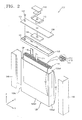
- FIG. 2 is an exploded perspective view of FIG. 1 .
- FIG. 3 is a cross-sectional view taken along a line III-III of FIG. 1 .
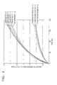
- FIG. 4 is a graph showing an amount of impregnated electrolyte of each rechargeable battery according to Embodiments of the invention 1-1, 1-2, 1-3, 2-1, 2-2, and 2-3 and Comparative Examples 1-1, 1-2, and 1-3, with respect to time.
- an X-X direction is a width direction of the rechargeable battery 100
- a Y-Y direction is a thickness direction of the rechargeable battery 100
- a Z-Z direction of the rechargeable battery 100 is a height direction of the rechargeable battery 100.
- a cross-sectional area of the rechargeable battery 100 extends along an XY plane, and a height of the rechargeable battery 100 is in a direction perpendicular to the cross-sectional area, i.e., in a direction (the Z-Z direction) perpendicular to the thickness direction.
- the rechargeable battery 100 has a thin thickness.
- the rechargeable battery may have a thickness that is less than or equal to about 8 mm.
- the thickness of the rechargeable battery 100 may be less than or equal to about 7 mm.
- the rechargeable battery 100 includes an electrode assembly 110, an electrolyte E, a can 120 accommodating the electrolyte E and the electrode assembly 110, a cap plate 130 sealing inside the can 120, and a first insulator 150.
- the electrode assembly 110 includes a first electrode plate 111 and a second electrode plate 112, on which an electrode active material is coated, and a separator 113 disposed between the first and second electrode plates 111 and 112.
- the electrode assembly 110 may be manufactured by forming a stacked structure wherein the first electrode plate 111, the separator 113, and the second electrode plate 112 are sequentially stacked in the stated order, and then winding the stacked structure in a jelly roll shape.
- the first and second electrode plates 111 and 112 may be respectively electrically connected to a first electrode tab 114 and a second electrode tab 115 for externally drawing out electrical charges formed via a chemical reaction.
- the first and second electrode tabs 114 and 115 may extend towards the same direction. For example, the first and second electrode tabs 114 and 115 may extend towards an opening OP of the can 120.
- the electrode assembly 110 has a jelly roll shape.
- the electrode assembly 110 may have a stacked structure wherein the first electrode plate 111, the separator 113, and the second electrode plate 112 are stacked in the stated order.
- the electrolyte E may have a viscosity of about 1 Pa ⁇ s to about 15 Pa ⁇ s at a temperature from about 20°C to about 25°C.
- the electrolyte E may include a cyclic carbonate-based material, a linear carbonate-based material, and a lithium salt.
- the electrolyte E may include at least one of ethylene carbonate (EC), propylene carbonate (PC), vinylene carbonate (VC), and vinyl ethylene carbonate (VEC) as the cyclic carbonate-based material.
- the electrolyte E may include at least one of ethyl methyl carbonate (EMC), dimethyl carbonate (DMC), and diethyl carbonate (DEC) as the linear carbonate-based material.
- the electrolyte E may include at least one of LiPF 6 and LiBF 4 as the lithium salt.
- the electrolyte E may include at least one material selected from the group of LiPF 6 , LiBF 4 , LiAsF 6 , LiClO 4 , LiCF 3 SO 3 , LiC(SO 2 CF 3 ) 3 , LiN(CF 3 SO 2 ) 2 , and LiCH(CF 3 SO 2 ) 2 as the lithium salt.
- the can 120 has a hexahedral shape, wherein a surface corresponding to a top surface is opened.
- the can 120 may be formed of a metallic material so as to provide strength.
- the can 120 includes the opening OP at a location corresponding to the top surface.
- the can 120 further includes a bottom surface 120bt opposite to the opening OP, and first through fourth side surfaces 120s1, 120s2, 120s3, and 120s4, which are disposed between the opening OP and the bottom surface 120bt and are perpendicularly bent with respect to the bottom surface 120bt.
- the first and second side surfaces 120s1 and 120s2 are parallel to each other and disposed opposite to each other.
- the third and fourth side surfaces 120s3 and 120s4 are parallel to each other and disposed opposite to each other. Widths of the first and second side surfaces 120s1 and 120s2 are smaller than widths of the third and fourth side surfaces 120s3 and 120s4.
- the electrolyte E, and the electrode assembly 110 impregnated in the electrolyte E are accommodated in the can 120.
- the electrode assembly 110 is accommodated in the can 120 while being surrounded by an insulating sheet 170 in order to prevent an undesirable short circuit with the can 120, particularly if the can 120 is formed of a metallic material.
- the opening OP may be sealed by the cap plate 130.
- a region where the cap plate 130 and the can 120 contact each other may be combined via laser welding so as to seal the can 120 and maintain internal air-tightness.
- the cap plate 130 includes an electrolyte injection hole 131. After the cap plate 130 and the can 120 are combined, the electrolyte E may be injected through the electrolyte injection hole 131, and then the electrolyte injection hole 131 may be sealed by a stopper 132.
- An electrode terminal 140 is disposed on the cap plate 130.
- a top surface of the electrode terminal 140 is externally exposed through a top of the cap plate 130.
- a bottom of the electrode terminal 140 faces the inside of the can 120 through the cap plate 130.
- the cap plate 130 is formed of a metallic material. As shown in FIG. 3 , the electrode terminal 140 is electrically connected to the first electrode tab 114 of the electrode assembly 110 to provide a first polarity. The cap plate 130 is electrically connected to the second electrode tab 115 of the electrode assembly 110 to provide a second polarity. If the can 120 is connected to the can plate 130 via welding, for example, the can 120 may also provide the second polarity.
- the cap plate 130 may operate as a positive electrode of the rechargeable battery 100, and the electrode terminal 140 may operate as a negative electrode of the rechargeable battery 100.
- a first gasket 145 and a second gasket 146 which include an insulator, may be used to prevent a short between the cap plate 130 and the electrode terminal 140.
- the first gasket 145 is disposed to contact a top surface of the cap plate 130, and the second gasket 146 may be disposed to contact a bottom surface of the cap plate 130.
- the first and second gaskets 145 and 146 are shown as being individual members. In other implementations, the first and second gaskets 145 and 146 may be integrated with each other.
- An insulating film 160 covering the first and second side surfaces 120s1 and 120s2 of the can 120 is adhered to the can 120 in order to electrically insulate the can 120 from an external object.
- the can 120 may have the second polarity due to welding or other electrical connection with the cap plate 130.
- the first insulator 150 is located on the electrode assembly 110 in the can 120.
- the first insulator 150 may insulate the electrode assembly 110 from the cap plate 130.
- the first insulator 150 may insulate the electrode assembly 110 from the cap plate 130 while restricting the electrode assembly 110 from moving inside the can 120.
- the first insulator 150 includes a through hole such that the first and second electrode tabs 114 and 115 extend towards the opening OP, and includes a hole 151 at a location corresponding to the electrolyte injection hole 131 such that the electrolyte E injected through the electrolyte injection hole 131 may pass therethrough.
- a second insulator 180 is disposed below the electrode assembly 110 so as to prevent an undesirable short circuit between the can 120 and the electrode assembly 110, which may include metallic materials.
- the thickness of the rechargeable battery 100 according to this embodiment may be less than or equal to about 8 mm.
- the thickness of the rechargeable battery 100 may be less than or equal to about 7 mm.
- the rechargeable battery 100 having such a small thickness may have following structure and conditions in order to increase an impregnation efficiency of the electrolyte E.
- the can 120 may have an approximate hexahedral shape.
- a ratio of a height h1 of the can 120 to a cross-sectional area Ac of the can 120 may satisfy at least one of following conditions.
- the cross-sectional area Ac of the can 120 denotes a cross-sectional area in a direction perpendicular to the height of the can 120, i.e., a cross-sectional area of the can 120 according to an XY plane.
- the cross-sectional area Ac is computed according to square units using the same unit of measurement used to determine the height h1. Thereafter, the units of measurement are dropped in computing the ratio of the height h1 of the can 120 to the cross-sectional area Ac and in converting the ratio into a percent value.
- Condition 1 defines the ratio of the height h1 of the can 120 to the cross-sectional area Ac of the can 120.
- the impregnation efficiency of the electrode assembly 110 in the electrolyte E having viscosity of about 1 Pa ⁇ s to about 15 at a temperature from about 20°C to about 25°C may be increased. If h1/Ac is less than 12.5% or higher than 25%, impregnation speed and efficiency of the electrode assembly 110 with respect to the electrolyte E may be decreased, and thus the rechargeable battery 100 may not provide sufficient performance.
- FIG. 4 is a graph showing an amount of impregnated electrolyte of each rechargeable battery according to Embodiments 1-1, 1-2, 1-3, 2-1, 2-2, and 2-3 and Comparative Examples 1-1, 1-2, and 1-3, with respect to time.
- thicknesses of the rechargeable batteries according to Embodiments 11-1, 1-2, 1-3, 2-1, 2-2, and 2-3 and Comparative Examples 1-1, 1-2, and 1-3 were the same and were less than or equal to 8 mm.
- Embodiments 1-1, 1-2, 1-3, 2-1, 2-2, and 2-3 satisfied Condition 1, whereas Comparative Examples 1-1, 1-2, and 1-3 did not satisfy Condition 1.
- the rechargeable batteries according to Embodiments 1-1, 1-2, and 1-3 had a cross-sectional area of 354 mm 2 and a height of 80 mm, providing a value for Condition 1 of about 22.60%.
- the rechargeable batteries according to Embodiments 2-1, 2-2, and 2-3 had a cross-sectional area of 270 mm 2 and a height of 65 mm, providing a value for Condition 1 of about 24.07%.
- the rechargeable batteries according to Comparative Examples 1-1, 1-2, and 1-3 had a cross-sectional area of 170 mm 2 and a height of 80 mm, providing a value for Condition 1 of about 47.06%.
- the amounts of impregnated electrolyte of Embodiments 1-1, 1-2, and 1-3, 2-1, 2-2, and 2-3 were about 2.8 to about 3.4 mg after about 150 seconds, whereas the amounts of impregnated electrolyte of Comparative Examples 1-1, 1-2, and 1-3 were about 1.0 to about 1.3 mg after about 150 seconds.
- the amounts of impregnated electrolyte of Embodiments 1-1,1-2,1-3, 2-1, 2-2, and 2-3 satisfying Condition 1 were about 3 times the amounts of impregnated electrolyte of Comparative Examples 1-1, 1-2, and 1-3 which did not Condition 1, with respect to the same amount of time.
- the cross-sectional area Ac of the can 120 may be from about 210 mm 2 to about 560 mm 2 , and the height h1 of the can 120 may be from about 70 mm to about 110 mm. If the height h1 is less than 70 mm, the rechargeable battery 100 may not have a sufficient output even for a small device, such as a mobile phone. Accordingly, such a rechargeable battery may be undesirable. On the other hand, if the height h1 is higher than 110 mm, the impregnation efficiency of the electrode assembly 110 in the electrolyte E may be decreased.
- the electrode assembly 110 accommodated in the can 120 satisfying Condition 1 may increase the impregnation efficiency of the electrolyte E when Condition 2 is satisfied.
- Condition 2 defines a ratio of a cross-sectional area Ae of the electrode assembly 110 to the cross-sectional area Ac of the can 120.
- Ae/Ac energy density and output (Wh) of the rechargeable battery 100 may be low.
- Wh energy density and output
- Ae/Ac is higher than 95%, the impregnation efficiency may be decreased and it may be difficult to accommodate an amount of the electrolyte E sufficient for an operation of the rechargeable battery 100 that is repeatably charged and discharged for a long period of time.
- a height h2 of the electrode assembly 110 may satisfy Condition 3 below.
- Condition 3 defines a ratio of the height h2 of the electrode assembly 110 to the height h1 of the can 120.
- h2/h1 is lower than 90%, the energy density of the rechargeable battery 100 may be decreased and the electrode assembly 110 may move inside the can 120.
- Safety of the rechargeable battery 100 may be threatened when the rechargeable battery 100 is dropped or the like.
- h2/h1 is higher than 98%, assembling of the rechargeable battery 100 may be difficult, and thus, safety and reliability of the rechargeable battery 100 may be decreased.
- an impregnation efficiency of an electrolyte having viscosity of 1 Pa ⁇ s to 15 Pa ⁇ s may be be increased at a temperature from 20°C to 25°C.
Landscapes
- Chemical & Material Sciences (AREA)
- Chemical Kinetics & Catalysis (AREA)
- Electrochemistry (AREA)
- General Chemical & Material Sciences (AREA)
- Physics & Mathematics (AREA)
- Condensed Matter Physics & Semiconductors (AREA)
- General Physics & Mathematics (AREA)
- Inorganic Chemistry (AREA)
- Engineering & Computer Science (AREA)
- Manufacturing & Machinery (AREA)
- Secondary Cells (AREA)
- Filling, Topping-Up Batteries (AREA)
- Sealing Battery Cases Or Jackets (AREA)
Abstract
Description
- The present invention relates to a rechargeable battery.
- As wireless internet and communication technologies have developed, the supply of mobile phones or portable computers operable by using a rechargeable battery instead of a fixed power supply apparatus has rapidly increased. Generally, mobile phones and portable computers are small, are easy to carry, and have excellent mobility. Thus, mobile phones and portable computers are widely used for business or personal use, and accordingly, the demand for rechargeable batteries has been increasing.
- As the performance of electronic devices, such as mobile phones and portable computers, has gradually improved, high energy performance, for example, high performance in terms of energy density/output, is becoming more desirable in rechargeable batteries. In addition, it is becoming desirable for the thickness of rechargeable batteries used in the such electronic devices to be reduced to be compatible with slimmer electronic devices.
- In order to provide a high energy density and/or high output, the rechargeable battery should sufficiently include an electrode assembly and an electrolyte. However, it may be difficult to make electronic devices slimmer if the rechargeable battery is expected to have a high performance. At the same time, it may be difficult to manufacture a rechargeable battery to have a high performance if the electronic devices are made to be slimmer.
- One or more embodiments include a rechargeable battery having a thin thickness, and more particularly, a rechargeable battery that increases an impregnation efficiency of an electrolyte.
- Embodiments of the invention are directed to a rechargeable battery including an electrode assembly including a first electrode plate, a second electrode plate, and a separator between the first and second electrode plates, an electrolyte having viscosity of about 1 Pa·s to about 15 Pa·s at a temperature from about 20°C to about 25°C, a can having an opening which the electrode assembly is inserted, the electrode assembly and the electrolyte being accommodated inside the can, and a cap plate that seals the opening of the can. A ratio of a height of the can to a cross-sectional area of the can is from about 12.5% to about 25%.
- The cross-sectional area of the can may be a cross-sectional area in a direction perpendicular to the height of the can.
- The cross-sectional area of the can may be from about 210 mm2 to about 560 mm2.
- The height of the can may be from about 70 mm to about 110 mm.
- A cross-sectional area of the electrode assembly may be about 85% to about 95% of the cross-sectional area of the can.
- A height of the electrode assembly may be about 90% to about 98% of the height of the can.
- The cap plate may include an electrolyte injection hole.
- The rechargeable battery may further include an insulator between the electrode assembly and the cap plate, in the can.
- The insulator may include a through hole at a location corresponding to the electrolyte injection hole.
- The electrolyte may include a cyclic carbonate-based material, a linear carbonate-based material, and a lithium salt.
- Embodiments of the invention are also directed to a rechargeable battery, the rechargeable battery including an electrode assembly including a first electrode plate, a second electrode plate, and a separator between the first and second electrode plates, an electrolyte having viscosity of about 1 Pa·s to 15 Pa·s at a temperature from about 20°C to about 25°C, a can having an opening through which the electrode assembly is inserted, the electrode assembly and the electrolyte being inserted inside the can, and the can having an overall hexahedral shape including a bottom surface parallel to the opening and side surfaces disposed between the opening and the bottom surface, and a cap plate that seals the opening of the can, the cap plate including an electrolyte injection hole into which the electrolyte is injected. A ratio of a height of the can to a cross-sectional area of the can is from about 12.5% to about 25%.
- The cross-sectional area of the can may be from about 210 mm2 to about 560 mm2.
- The height of the can may be from about 70 mm to about 110 mm.
- A cross-sectional area of the electrode assembly may be about 85% to about 95% of the cross-sectional area of the can.
- A height of the electrode assembly may be about 90% to about 98% of the height of the can.
- The rechargeable battery may further include an insulator in the can between the electrode assembly and the cap plate. The insulator may include a through hole at a location corresponding to the electrolyte injection hole.
- The opening of the can sealed by the cap plate may be at a location corresponding to a top surface. The bottom surface may be opposite to the cap plate. The side surfaces may include a first side surface between the cap plate and the bottom surface and approximately perpendicular to the bottom surface, a second side surface between the cap plate and the bottom surface and approximately perpendicular to the bottom surface, and facing the first side surface, a third side surface between the cap plate and the bottom surface and approximately perpendicular to the bottom surface and the first side surface, and a fourth side surface between the cap plate and the bottom surface and approximately perpendicular to the bottom surface, and facing the third side surface.
- At least some of the above and other features of the invention are set out in the claims.
- Features of the invention will be made more apparent to those of skill in the art by describing embodiments of the invention with reference to the attached drawings in which:
-
FIG. 1 illustrates a perspective view schematically showing a rechargeable battery according to an embodiment of the invention; -
FIG. 2 illustrates an exploded perspective view ofFIG. 1 ; -
FIG. 3 illustrates a cross-sectional view taken along a line III-III ofFIG. 1 ; and -
FIG. 4 illustrates a graph showing an amount of impregnated electrolyte of each rechargeable battery according to Embodiments 1-1, 1-2, 1-3, 2-1, 2-2, and 2-3 and Comparative Examples 1-1, 1-2, and 1-3, with respect to time. - Example embodiments of the invention will now be described more fully hereinafter with reference to the accompanying drawings; however, the invention may be embodied in different forms and should not be construed as limited to the embodiments set forth herein. Rather, these embodiments are provided so that this disclosure will be thorough and complete, and will fully convey exemplary implementations to those skilled in the art.
- In the drawing figures, the dimensions of layers and regions may be exaggerated for clarity of illustration. Like reference numerals refer to like elements throughout.
- As the invention allows for various changes and numerous embodiments, particular embodiments will be illustrated in the drawings and described in detail in the written description. However, this is not intended to limit the present invention to particular modes of practice, and it will to be appreciated that all changes, equivalents, and substitutes that do not depart from the technical scope are encompassed in the present invention. In the description, certain detailed explanations of related art are omitted when it is deemed that they may unnecessarily obscure the essence of the invention. While such terms as "first," "second," etc., may be used to describe various components, such components must not be limited to the above terms. The above terms are used only to distinguish one component from another. The terms used in the present specification are merely used to describe particular embodiments, and are not intended to limit the present invention. An expression used in the singular encompasses the expression of the plural, unless it has a clearly different meaning in the context. In the present specification, it is to be understood that the terms such as "including" or "having," etc., are intended to indicate the existence of the features, numbers, steps, actions, components, parts, or combinations thereof disclosed in the specification, and are not intended to preclude the possibility that one or more other features, numbers, steps, actions, components, parts, or combinations thereof may exist or may be added. "/" used herein may be interpreted as "and" or "or" according to situations. Also, expressions such as "at least one of," when preceding a list of elements, modify the entire list of elements and do not modify the individual elements of the list.
-
FIG. 1 illustrates a perspective view schematically of arechargeable battery 100 according to an embodiment of the invention.FIG. 2 is an exploded perspective view ofFIG. 1 .FIG. 3 is a cross-sectional view taken along a line III-III ofFIG. 1 .FIG. 4 is a graph showing an amount of impregnated electrolyte of each rechargeable battery according to Embodiments of the invention 1-1, 1-2, 1-3, 2-1, 2-2, and 2-3 and Comparative Examples 1-1, 1-2, and 1-3, with respect to time. - In
FIG. 1 , an X-X direction is a width direction of therechargeable battery 100, a Y-Y direction is a thickness direction of therechargeable battery 100, and a Z-Z direction of therechargeable battery 100 is a height direction of therechargeable battery 100. A cross-sectional area of therechargeable battery 100 extends along an XY plane, and a height of therechargeable battery 100 is in a direction perpendicular to the cross-sectional area, i.e., in a direction (the Z-Z direction) perpendicular to the thickness direction. - Referring to
FIGS. 1 through 3 , therechargeable battery 100 according to this embodiment has a thin thickness. For example, the rechargeable battery may have a thickness that is less than or equal to about 8 mm. In detail, the thickness of therechargeable battery 100 may be less than or equal to about 7 mm. Therechargeable battery 100 includes anelectrode assembly 110, an electrolyte E, a can 120 accommodating the electrolyte E and theelectrode assembly 110, acap plate 130 sealing inside thecan 120, and afirst insulator 150. - The
electrode assembly 110 includes afirst electrode plate 111 and asecond electrode plate 112, on which an electrode active material is coated, and aseparator 113 disposed between the first andsecond electrode plates electrode assembly 110 may be manufactured by forming a stacked structure wherein thefirst electrode plate 111, theseparator 113, and thesecond electrode plate 112 are sequentially stacked in the stated order, and then winding the stacked structure in a jelly roll shape. The first andsecond electrode plates first electrode tab 114 and asecond electrode tab 115 for externally drawing out electrical charges formed via a chemical reaction. The first andsecond electrode tabs second electrode tabs can 120. - In the current embodiment, the
electrode assembly 110 has a jelly roll shape. In other implementations, theelectrode assembly 110 may have a stacked structure wherein thefirst electrode plate 111, theseparator 113, and thesecond electrode plate 112 are stacked in the stated order. - The electrolyte E may have a viscosity of about 1 Pa·s to about 15 Pa·s at a temperature from about 20°C to about 25°C. For example, the electrolyte E may include a cyclic carbonate-based material, a linear carbonate-based material, and a lithium salt. The electrolyte E may include at least one of ethylene carbonate (EC), propylene carbonate (PC), vinylene carbonate (VC), and vinyl ethylene carbonate (VEC) as the cyclic carbonate-based material. The electrolyte E may include at least one of ethyl methyl carbonate (EMC), dimethyl carbonate (DMC), and diethyl carbonate (DEC) as the linear carbonate-based material. The electrolyte E may include at least one of LiPF6 and LiBF4 as the lithium salt. In other implementations, the electrolyte E may include at least one material selected from the group of LiPF6, LiBF4, LiAsF6, LiClO4, LiCF3SO3, LiC(SO2CF3)3, LiN(CF3SO2)2, and LiCH(CF3SO2)2 as the lithium salt.
- The can 120 has a hexahedral shape, wherein a surface corresponding to a top surface is opened. The can 120 may be formed of a metallic material so as to provide strength. As shown in
FIG. 2 , thecan 120 includes the opening OP at a location corresponding to the top surface. The can 120 further includes a bottom surface 120bt opposite to the opening OP, and first through fourth side surfaces 120s1, 120s2, 120s3, and 120s4, which are disposed between the opening OP and the bottom surface 120bt and are perpendicularly bent with respect to the bottom surface 120bt. The first and second side surfaces 120s1 and 120s2 are parallel to each other and disposed opposite to each other. The third and fourth side surfaces 120s3 and 120s4 are parallel to each other and disposed opposite to each other. Widths of the first and second side surfaces 120s1 and 120s2 are smaller than widths of the third and fourth side surfaces 120s3 and 120s4. - The electrolyte E, and the
electrode assembly 110 impregnated in the electrolyte E are accommodated in thecan 120. Theelectrode assembly 110 is accommodated in thecan 120 while being surrounded by an insulatingsheet 170 in order to prevent an undesirable short circuit with thecan 120, particularly if thecan 120 is formed of a metallic material. After theelectrode assembly 110 is accommodated in thecan 120, the opening OP may be sealed by thecap plate 130. A region where thecap plate 130 and thecan 120 contact each other may be combined via laser welding so as to seal thecan 120 and maintain internal air-tightness. - The
cap plate 130 includes anelectrolyte injection hole 131. After thecap plate 130 and thecan 120 are combined, the electrolyte E may be injected through theelectrolyte injection hole 131, and then theelectrolyte injection hole 131 may be sealed by astopper 132. - An
electrode terminal 140 is disposed on thecap plate 130. A top surface of theelectrode terminal 140 is externally exposed through a top of the cap plate 130.A bottom of theelectrode terminal 140 faces the inside of thecan 120 through thecap plate 130. - The
cap plate 130 is formed of a metallic material. As shown inFIG. 3 , theelectrode terminal 140 is electrically connected to thefirst electrode tab 114 of theelectrode assembly 110 to provide a first polarity. Thecap plate 130 is electrically connected to thesecond electrode tab 115 of theelectrode assembly 110 to provide a second polarity. If thecan 120 is connected to the can plate 130 via welding, for example, thecan 120 may also provide the second polarity. - For example, the
cap plate 130 may operate as a positive electrode of therechargeable battery 100, and theelectrode terminal 140 may operate as a negative electrode of therechargeable battery 100. Afirst gasket 145 and asecond gasket 146, which include an insulator, may be used to prevent a short between thecap plate 130 and theelectrode terminal 140. Thefirst gasket 145 is disposed to contact a top surface of thecap plate 130, and thesecond gasket 146 may be disposed to contact a bottom surface of thecap plate 130. InFIG. 2 , the first andsecond gaskets second gaskets film 160 covering the first and second side surfaces 120s1 and 120s2 of thecan 120 is adhered to thecan 120 in order to electrically insulate thecan 120 from an external object. As noted above, thecan 120 may have the second polarity due to welding or other electrical connection with thecap plate 130. - The
first insulator 150 is located on theelectrode assembly 110 in thecan 120. Thefirst insulator 150 may insulate theelectrode assembly 110 from thecap plate 130. Thefirst insulator 150 may insulate theelectrode assembly 110 from thecap plate 130 while restricting theelectrode assembly 110 from moving inside thecan 120. Thefirst insulator 150 includes a through hole such that the first andsecond electrode tabs hole 151 at a location corresponding to theelectrolyte injection hole 131 such that the electrolyte E injected through theelectrolyte injection hole 131 may pass therethrough. Asecond insulator 180 is disposed below theelectrode assembly 110 so as to prevent an undesirable short circuit between thecan 120 and theelectrode assembly 110, which may include metallic materials. - The thickness of the
rechargeable battery 100 according to this embodiment may be less than or equal to about 8 mm. For example, the thickness of therechargeable battery 100 may be less than or equal to about 7 mm. Therechargeable battery 100 having such a small thickness may have following structure and conditions in order to increase an impregnation efficiency of the electrolyte E. - For example, the
can 120 may have an approximate hexahedral shape. When theelectrode assembly 110 and the electrolyte E are accommodated in thecan 120, a ratio of a height h1 of thecan 120 to a cross-sectional area Ac of thecan 120 may satisfy at least one of following conditions. The cross-sectional area Ac of thecan 120 denotes a cross-sectional area in a direction perpendicular to the height of thecan 120, i.e., a cross-sectional area of thecan 120 according to an XY plane. The cross-sectional area Ac is computed according to square units using the same unit of measurement used to determine the height h1. Thereafter, the units of measurement are dropped in computing the ratio of the height h1 of thecan 120 to the cross-sectional area Ac and in converting the ratio into a percent value. - Condition 1 defines the ratio of the height h1 of the
can 120 to the cross-sectional area Ac of thecan 120. When Condition 1 is satisfied, the impregnation efficiency of theelectrode assembly 110 in the electrolyte E having viscosity of about 1 Pa·s to about 15 at a temperature from about 20°C to about 25°C may be increased. If h1/Ac is less than 12.5% or higher than 25%, impregnation speed and efficiency of theelectrode assembly 110 with respect to the electrolyte E may be decreased, and thus therechargeable battery 100 may not provide sufficient performance. -
FIG. 4 is a graph showing an amount of impregnated electrolyte of each rechargeable battery according to Embodiments 1-1, 1-2, 1-3, 2-1, 2-2, and 2-3 and Comparative Examples 1-1, 1-2, and 1-3, with respect to time. InFIG. 4 , thicknesses of the rechargeable batteries according to Embodiments 11-1, 1-2, 1-3, 2-1, 2-2, and 2-3 and Comparative Examples 1-1, 1-2, and 1-3 were the same and were less than or equal to 8 mm. Embodiments 1-1, 1-2, 1-3, 2-1, 2-2, and 2-3 satisfied Condition 1, whereas Comparative Examples 1-1, 1-2, and 1-3 did not satisfy Condition 1. - The rechargeable batteries according to Embodiments 1-1, 1-2, and 1-3 had a cross-sectional area of 354 mm2 and a height of 80 mm, providing a value for Condition 1 of about 22.60%. The rechargeable batteries according to Embodiments 2-1, 2-2, and 2-3 had a cross-sectional area of 270 mm2 and a height of 65 mm, providing a value for Condition 1 of about 24.07%. On the other hand, the rechargeable batteries according to Comparative Examples 1-1, 1-2, and 1-3 had a cross-sectional area of 170 mm2 and a height of 80 mm, providing a value for Condition 1 of about 47.06%.
- Referring to
FIG. 4 , the amounts of impregnated electrolyte of Embodiments 1-1, 1-2, and 1-3, 2-1, 2-2, and 2-3 were about 2.8 to about 3.4 mg after about 150 seconds, whereas the amounts of impregnated electrolyte of Comparative Examples 1-1, 1-2, and 1-3 were about 1.0 to about 1.3 mg after about 150 seconds. The amounts of impregnated electrolyte of Embodiments 1-1,1-2,1-3, 2-1, 2-2, and 2-3 satisfying Condition 1 were about 3 times the amounts of impregnated electrolyte of Comparative Examples 1-1, 1-2, and 1-3 which did not Condition 1, with respect to the same amount of time. - According to an embodiment, the cross-sectional area Ac of the
can 120 may be from about 210 mm2 to about 560 mm2, and the height h1 of thecan 120 may be from about 70 mm to about 110 mm. If the height h1 is less than 70 mm, therechargeable battery 100 may not have a sufficient output even for a small device, such as a mobile phone. Accordingly, such a rechargeable battery may be undesirable. On the other hand, if the height h1 is higher than 110 mm, the impregnation efficiency of theelectrode assembly 110 in the electrolyte E may be decreased. - The
electrode assembly 110 accommodated in thecan 120 satisfying Condition 1 may increase the impregnation efficiency of the electrolyte E when Condition 2 is satisfied. - Condition 2 defines a ratio of a cross-sectional area Ae of the
electrode assembly 110 to the cross-sectional area Ac of thecan 120. When Ae/Ac is lower than 85%, energy density and output (Wh) of therechargeable battery 100 may be low. When Ae/Ac is higher than 95%, the impregnation efficiency may be decreased and it may be difficult to accommodate an amount of the electrolyte E sufficient for an operation of therechargeable battery 100 that is repeatably charged and discharged for a long period of time. - A height h2 of the
electrode assembly 110 may satisfyCondition 3 below. -
Condition 3 defines a ratio of the height h2 of theelectrode assembly 110 to the height h1 of thecan 120. When h2/h1 is lower than 90%, the energy density of therechargeable battery 100 may be decreased and theelectrode assembly 110 may move inside thecan 120. Safety of therechargeable battery 100 may be threatened when therechargeable battery 100 is dropped or the like. When h2/h1 is higher than 98%, assembling of therechargeable battery 100 may be difficult, and thus, safety and reliability of therechargeable battery 100 may be decreased. - As described above, according to the one or more of the above embodiments, an impregnation efficiency of an electrolyte having viscosity of 1 Pa·s to 15 Pa·s may be be increased at a temperature from 20°C to 25°C.
- Example embodiments of the invention have been disclosed herein, and although specific terms are employed, they are used and are to be interpreted in a generic and descriptive sense only and not for purpose of limitation. Accordingly, it will be understood by those of skill in the art that various changes in form and details may be made without departing from the scope as set forth in the following claims.
Claims (12)
- A rechargeable battery comprising:an electrode assembly including a first electrode plate, a second electrode plate, and a separator between the first and second electrode plates;an electrolyte having viscosity of from 1 Pa·s to 15 Pa·s at a temperature of from 20°C to about 25°C;a can having an opening through which the electrode assembly is inserted, the electrode assembly and the electrolyte being accommodated inside the can; anda cap plate that seals the opening of the can,wherein a ratio of a height of the can to a cross-sectional area of the can is from 12.5% to 25%.
- A rechargeable battery as claimed in claim 1, wherein the cross-sectional area of the can is a cross-sectional area in a direction perpendicular to the height of the can.
- A rechargeable battery as claimed in claim 1 or 2, wherein the cross-sectional area of the can is from about 210 mm2 to about 560 mm2.
- A rechargeable battery as claimed in any preceding claim, wherein the height of the can is from about 70 mm to about 110 mm.
- A rechargeable battery as claimed in any preceding claim, wherein a cross-sectional area of the electrode assembly is from 85% to 95% of the cross-sectional area of the can.
- A rechargeable battery as claimed in any preceding claim, wherein a height of the electrode assembly is from 90% to 98% of the height of the can.
- A rechargeable battery as claimed in any preceding claim, wherein the cap plate includes an electrolyte injection hole.
- A rechargeable battery as claimed in claim 7, further comprising an insulator in the can between the electrode assembly and the cap plate.
- A rechargeable battery as claimed in claim 8, wherein the insulator includes a through hole at a location corresponding to the electrolyte injection hole.
- A rechargeable battery as claimed in any preceding claim, wherein the electrolyte includes a cyclic carbonate-based material, a linear carbonate-based material, and a lithium salt.
- A rechargeable battery according to any preceding claim:wherein the can has an overall hexahedral shape including a bottom surface parallel to the opening and side surfaces disposed between the opening and the bottom surface.
- A rechargeable battery as claimed in claim 11, wherein:the opening of the can sealed by the cap plate is at a location corresponding to a top surface,the bottom surface is opposite to the cap plate, andthe side surfaces include:a first side surface between the cap plate and the bottom surface and approximately perpendicular to the bottom surface;a second side surface between the cap plate and the bottom surface and approximately perpendicular to the bottom surface, and facing the first side surface;a third side surface between the cap plate and the bottom surface and approximately perpendicular to the bottom surface and the first side surface; anda fourth side surface between the cap plate and the bottom surface and approximately perpendicular to the bottom surface, and facing the third side surface.
Applications Claiming Priority (2)
| Application Number | Priority Date | Filing Date | Title |
|---|---|---|---|
| KR20120148089 | 2012-12-18 | ||
| KR1020130011991A KR20140079693A (en) | 2012-12-18 | 2013-02-01 | Rechargeable battery |
Publications (2)
| Publication Number | Publication Date |
|---|---|
| EP2747188A1 true EP2747188A1 (en) | 2014-06-25 |
| EP2747188B1 EP2747188B1 (en) | 2017-06-21 |
Family
ID=49882846
Family Applications (1)
| Application Number | Title | Priority Date | Filing Date |
|---|---|---|---|
| EP13198234.0A Active EP2747188B1 (en) | 2012-12-18 | 2013-12-18 | Rechargeable battery having improved electrolyte impregnation efficiency |
Country Status (3)
| Country | Link |
|---|---|
| US (1) | US9917283B2 (en) |
| EP (1) | EP2747188B1 (en) |
| CN (1) | CN103872274B (en) |
Families Citing this family (3)
| Publication number | Priority date | Publication date | Assignee | Title |
|---|---|---|---|---|
| CN109411638B (en) * | 2017-08-18 | 2021-08-13 | 北京好风光储能技术有限公司 | A kind of lithium slurry battery, module and preparation method thereof |
| EP4369510A4 (en) * | 2021-11-26 | 2025-07-23 | Contemporary Amperex Technology Hong Kong Ltd | BATTERY CELL, BATTERY, ELECTRICAL DEVICE AND METHOD AND DEVICE FOR PRODUCING A BATTERY CELL |
| US12191507B2 (en) * | 2022-09-07 | 2025-01-07 | Sk On Co., Ltd. | Battery cell |
Citations (4)
| Publication number | Priority date | Publication date | Assignee | Title |
|---|---|---|---|---|
| JPH06150971A (en) * | 1992-10-30 | 1994-05-31 | Sony Corp | Cylindrical nonaqueous electrolyte secondary battery |
| US6045944A (en) * | 1997-08-06 | 2000-04-04 | Kabushiki Kaisha Toshiba | Battery and method of manufacturing the same |
| US20060269842A1 (en) * | 2005-05-31 | 2006-11-30 | Matsushita Electric Industrial Co., Ltd. | Non-aqueous electrolyte secondary battery and battery module |
| US20100035132A1 (en) * | 2008-08-06 | 2010-02-11 | Joung-Hwan Park | Secondary battery |
Family Cites Families (6)
| Publication number | Priority date | Publication date | Assignee | Title |
|---|---|---|---|---|
| TW431004B (en) * | 1998-10-29 | 2001-04-21 | Toshiba Corp | Nonaqueous electrolyte secondary battery |
| JP3727840B2 (en) * | 2000-09-29 | 2005-12-21 | 株式会社東芝 | Battery pack and portable electronic device |
| JP2002164025A (en) * | 2000-11-22 | 2002-06-07 | Matsushita Electric Ind Co Ltd | Prismatic rechargeable battery |
| KR20040042375A (en) | 2002-11-14 | 2004-05-20 | 삼성에스디아이 주식회사 | Jelly-roll electrode assembly and secondary battery therewith |
| KR100928129B1 (en) | 2006-01-11 | 2009-11-25 | 삼성에스디아이 주식회사 | Secondary battery |
| KR101163387B1 (en) | 2008-02-16 | 2012-07-12 | 주식회사 엘지화학 | Secondary Battery Containing Jelly-Roll Typed Electrode Assembly |
-
2013
- 2013-10-29 US US14/065,463 patent/US9917283B2/en active Active
- 2013-12-11 CN CN201310676185.3A patent/CN103872274B/en active Active
- 2013-12-18 EP EP13198234.0A patent/EP2747188B1/en active Active
Patent Citations (4)
| Publication number | Priority date | Publication date | Assignee | Title |
|---|---|---|---|---|
| JPH06150971A (en) * | 1992-10-30 | 1994-05-31 | Sony Corp | Cylindrical nonaqueous electrolyte secondary battery |
| US6045944A (en) * | 1997-08-06 | 2000-04-04 | Kabushiki Kaisha Toshiba | Battery and method of manufacturing the same |
| US20060269842A1 (en) * | 2005-05-31 | 2006-11-30 | Matsushita Electric Industrial Co., Ltd. | Non-aqueous electrolyte secondary battery and battery module |
| US20100035132A1 (en) * | 2008-08-06 | 2010-02-11 | Joung-Hwan Park | Secondary battery |
Also Published As
| Publication number | Publication date |
|---|---|
| CN103872274B (en) | 2018-04-13 |
| US20140170473A1 (en) | 2014-06-19 |
| US9917283B2 (en) | 2018-03-13 |
| EP2747188B1 (en) | 2017-06-21 |
| CN103872274A (en) | 2014-06-18 |
Similar Documents
| Publication | Publication Date | Title |
|---|---|---|
| TWI628834B (en) | Electrode assembly including coupling part between electrode tabs and electrode lead located in space portion | |
| CN107925118B (en) | Irregular structure of battery cell having cell case with improved sealing reliability | |
| US10340498B2 (en) | Electrode assembly with tab-lead coupler and method for manufacturing the same | |
| US10686209B2 (en) | Electrode assembly, battery cell including the electrode assembly, and method of preparing the battery cell | |
| EP2863449B1 (en) | Secondary battery | |
| KR101023870B1 (en) | Pouch Type Lithium Secondary Battery | |
| EP3327827B1 (en) | Battery cell comprising electrode lead having protruding extension and tab connector | |
| US10505230B2 (en) | Hybrid electrode assembly of stair-like structure | |
| KR102088700B1 (en) | Secondary Battery Comprising Tube-Typed Member Containing Extinguishing Agents | |
| CN110546809B (en) | Battery cells including sealing tape for accelerated heat transfer | |
| US20200313147A1 (en) | Secondary battery | |
| US20170194617A1 (en) | Rechargeable battery | |
| KR101798926B1 (en) | Secondary Battery Having Insulative Member with Improved Structural Stability against External Force | |
| EP2747188B1 (en) | Rechargeable battery having improved electrolyte impregnation efficiency | |
| KR20170029748A (en) | Secondary Battery Comprising Electrode Assembly with Protrusion Portion and Storage Member for Electrolyte | |
| KR20140079693A (en) | Rechargeable battery | |
| US20160351954A1 (en) | Secondary battery | |
| US10593999B2 (en) | Electrode assembly and rechargeable battery including the same | |
| WO2018221800A1 (en) | Secondary battery | |
| KR102080502B1 (en) | Pouch-typed Battery Cell Having Two or More Electrode Assemblies | |
| US20180102512A1 (en) | Electrode assembly comprising reinforcing member capable of minimizing deformation of electrode and stacked structure of unit cell by protecting unit cell from external impact | |
| US20150243953A1 (en) | Secondary battery | |
| KR20170001281A (en) | Secondary Battery of Irregular Structure Capable of Maximizing Interior Space Occupancy, and Device Having the Same |
Legal Events
| Date | Code | Title | Description |
|---|---|---|---|
| PUAI | Public reference made under article 153(3) epc to a published international application that has entered the european phase |
Free format text: ORIGINAL CODE: 0009012 |
|
| 17P | Request for examination filed |
Effective date: 20131218 |
|
| AK | Designated contracting states |
Kind code of ref document: A1 Designated state(s): AL AT BE BG CH CY CZ DE DK EE ES FI FR GB GR HR HU IE IS IT LI LT LU LV MC MK MT NL NO PL PT RO RS SE SI SK SM TR |
|
| AX | Request for extension of the european patent |
Extension state: BA ME |
|
| R17P | Request for examination filed (corrected) |
Effective date: 20141217 |
|
| RBV | Designated contracting states (corrected) |
Designated state(s): AL AT BE BG CH CY CZ DE DK EE ES FI FR GB GR HR HU IE IS IT LI LT LU LV MC MK MT NL NO PL PT RO RS SE SI SK SM TR |
|
| 17Q | First examination report despatched |
Effective date: 20160407 |
|
| RIC1 | Information provided on ipc code assigned before grant |
Ipc: H01M 2/02 20060101ALI20161122BHEP Ipc: H01M 10/05 20100101ALN20161122BHEP Ipc: H01M 2/36 20060101ALI20161122BHEP Ipc: H01M 10/0566 20100101AFI20161122BHEP |
|
| GRAP | Despatch of communication of intention to grant a patent |
Free format text: ORIGINAL CODE: EPIDOSNIGR1 |
|
| INTG | Intention to grant announced |
Effective date: 20170104 |
|
| GRAS | Grant fee paid |
Free format text: ORIGINAL CODE: EPIDOSNIGR3 |
|
| GRAA | (expected) grant |
Free format text: ORIGINAL CODE: 0009210 |
|
| AK | Designated contracting states |
Kind code of ref document: B1 Designated state(s): AL AT BE BG CH CY CZ DE DK EE ES FI FR GB GR HR HU IE IS IT LI LT LU LV MC MK MT NL NO PL PT RO RS SE SI SK SM TR |
|
| REG | Reference to a national code |
Ref country code: GB Ref legal event code: FG4D |
|
| REG | Reference to a national code |
Ref country code: CH Ref legal event code: EP |
|
| REG | Reference to a national code |
Ref country code: IE Ref legal event code: FG4D |
|
| REG | Reference to a national code |
Ref country code: AT Ref legal event code: REF Ref document number: 903696 Country of ref document: AT Kind code of ref document: T Effective date: 20170715 |
|
| REG | Reference to a national code |
Ref country code: DE Ref legal event code: R096 Ref document number: 602013022504 Country of ref document: DE |
|
| REG | Reference to a national code |
Ref country code: NL Ref legal event code: MP Effective date: 20170621 |
|
| PG25 | Lapsed in a contracting state [announced via postgrant information from national office to epo] |
Ref country code: LT Free format text: LAPSE BECAUSE OF FAILURE TO SUBMIT A TRANSLATION OF THE DESCRIPTION OR TO PAY THE FEE WITHIN THE PRESCRIBED TIME-LIMIT Effective date: 20170621 Ref country code: GR Free format text: LAPSE BECAUSE OF FAILURE TO SUBMIT A TRANSLATION OF THE DESCRIPTION OR TO PAY THE FEE WITHIN THE PRESCRIBED TIME-LIMIT Effective date: 20170922 Ref country code: FI Free format text: LAPSE BECAUSE OF FAILURE TO SUBMIT A TRANSLATION OF THE DESCRIPTION OR TO PAY THE FEE WITHIN THE PRESCRIBED TIME-LIMIT Effective date: 20170621 Ref country code: HR Free format text: LAPSE BECAUSE OF FAILURE TO SUBMIT A TRANSLATION OF THE DESCRIPTION OR TO PAY THE FEE WITHIN THE PRESCRIBED TIME-LIMIT Effective date: 20170621 Ref country code: NO Free format text: LAPSE BECAUSE OF FAILURE TO SUBMIT A TRANSLATION OF THE DESCRIPTION OR TO PAY THE FEE WITHIN THE PRESCRIBED TIME-LIMIT Effective date: 20170921 |
|
| REG | Reference to a national code |
Ref country code: LT Ref legal event code: MG4D |
|
| REG | Reference to a national code |
Ref country code: AT Ref legal event code: MK05 Ref document number: 903696 Country of ref document: AT Kind code of ref document: T Effective date: 20170621 |
|
| REG | Reference to a national code |
Ref country code: FR Ref legal event code: PLFP Year of fee payment: 5 |
|
| PG25 | Lapsed in a contracting state [announced via postgrant information from national office to epo] |
Ref country code: LV Free format text: LAPSE BECAUSE OF FAILURE TO SUBMIT A TRANSLATION OF THE DESCRIPTION OR TO PAY THE FEE WITHIN THE PRESCRIBED TIME-LIMIT Effective date: 20170621 Ref country code: NL Free format text: LAPSE BECAUSE OF FAILURE TO SUBMIT A TRANSLATION OF THE DESCRIPTION OR TO PAY THE FEE WITHIN THE PRESCRIBED TIME-LIMIT Effective date: 20170621 Ref country code: SE Free format text: LAPSE BECAUSE OF FAILURE TO SUBMIT A TRANSLATION OF THE DESCRIPTION OR TO PAY THE FEE WITHIN THE PRESCRIBED TIME-LIMIT Effective date: 20170621 Ref country code: BG Free format text: LAPSE BECAUSE OF FAILURE TO SUBMIT A TRANSLATION OF THE DESCRIPTION OR TO PAY THE FEE WITHIN THE PRESCRIBED TIME-LIMIT Effective date: 20170921 Ref country code: RS Free format text: LAPSE BECAUSE OF FAILURE TO SUBMIT A TRANSLATION OF THE DESCRIPTION OR TO PAY THE FEE WITHIN THE PRESCRIBED TIME-LIMIT Effective date: 20170621 |
|
| PG25 | Lapsed in a contracting state [announced via postgrant information from national office to epo] |
Ref country code: SK Free format text: LAPSE BECAUSE OF FAILURE TO SUBMIT A TRANSLATION OF THE DESCRIPTION OR TO PAY THE FEE WITHIN THE PRESCRIBED TIME-LIMIT Effective date: 20170621 Ref country code: CZ Free format text: LAPSE BECAUSE OF FAILURE TO SUBMIT A TRANSLATION OF THE DESCRIPTION OR TO PAY THE FEE WITHIN THE PRESCRIBED TIME-LIMIT Effective date: 20170621 Ref country code: RO Free format text: LAPSE BECAUSE OF FAILURE TO SUBMIT A TRANSLATION OF THE DESCRIPTION OR TO PAY THE FEE WITHIN THE PRESCRIBED TIME-LIMIT Effective date: 20170621 Ref country code: EE Free format text: LAPSE BECAUSE OF FAILURE TO SUBMIT A TRANSLATION OF THE DESCRIPTION OR TO PAY THE FEE WITHIN THE PRESCRIBED TIME-LIMIT Effective date: 20170621 Ref country code: AT Free format text: LAPSE BECAUSE OF FAILURE TO SUBMIT A TRANSLATION OF THE DESCRIPTION OR TO PAY THE FEE WITHIN THE PRESCRIBED TIME-LIMIT Effective date: 20170621 |
|
| PG25 | Lapsed in a contracting state [announced via postgrant information from national office to epo] |
Ref country code: ES Free format text: LAPSE BECAUSE OF FAILURE TO SUBMIT A TRANSLATION OF THE DESCRIPTION OR TO PAY THE FEE WITHIN THE PRESCRIBED TIME-LIMIT Effective date: 20170621 Ref country code: IS Free format text: LAPSE BECAUSE OF FAILURE TO SUBMIT A TRANSLATION OF THE DESCRIPTION OR TO PAY THE FEE WITHIN THE PRESCRIBED TIME-LIMIT Effective date: 20171021 Ref country code: SM Free format text: LAPSE BECAUSE OF FAILURE TO SUBMIT A TRANSLATION OF THE DESCRIPTION OR TO PAY THE FEE WITHIN THE PRESCRIBED TIME-LIMIT Effective date: 20170621 Ref country code: PL Free format text: LAPSE BECAUSE OF FAILURE TO SUBMIT A TRANSLATION OF THE DESCRIPTION OR TO PAY THE FEE WITHIN THE PRESCRIBED TIME-LIMIT Effective date: 20170621 Ref country code: IT Free format text: LAPSE BECAUSE OF FAILURE TO SUBMIT A TRANSLATION OF THE DESCRIPTION OR TO PAY THE FEE WITHIN THE PRESCRIBED TIME-LIMIT Effective date: 20170621 |
|
| REG | Reference to a national code |
Ref country code: DE Ref legal event code: R097 Ref document number: 602013022504 Country of ref document: DE |
|
| PLBE | No opposition filed within time limit |
Free format text: ORIGINAL CODE: 0009261 |
|
| STAA | Information on the status of an ep patent application or granted ep patent |
Free format text: STATUS: NO OPPOSITION FILED WITHIN TIME LIMIT |
|
| PG25 | Lapsed in a contracting state [announced via postgrant information from national office to epo] |
Ref country code: DK Free format text: LAPSE BECAUSE OF FAILURE TO SUBMIT A TRANSLATION OF THE DESCRIPTION OR TO PAY THE FEE WITHIN THE PRESCRIBED TIME-LIMIT Effective date: 20170621 |
|
| 26N | No opposition filed |
Effective date: 20180322 |
|
| REG | Reference to a national code |
Ref country code: CH Ref legal event code: PL |
|
| PG25 | Lapsed in a contracting state [announced via postgrant information from national office to epo] |
Ref country code: SI Free format text: LAPSE BECAUSE OF FAILURE TO SUBMIT A TRANSLATION OF THE DESCRIPTION OR TO PAY THE FEE WITHIN THE PRESCRIBED TIME-LIMIT Effective date: 20170621 |
|
| REG | Reference to a national code |
Ref country code: IE Ref legal event code: MM4A |
|
| PG25 | Lapsed in a contracting state [announced via postgrant information from national office to epo] |
Ref country code: MT Free format text: LAPSE BECAUSE OF NON-PAYMENT OF DUE FEES Effective date: 20171218 Ref country code: LU Free format text: LAPSE BECAUSE OF NON-PAYMENT OF DUE FEES Effective date: 20171218 |
|
| REG | Reference to a national code |
Ref country code: BE Ref legal event code: MM Effective date: 20171231 |
|
| PG25 | Lapsed in a contracting state [announced via postgrant information from national office to epo] |
Ref country code: IE Free format text: LAPSE BECAUSE OF NON-PAYMENT OF DUE FEES Effective date: 20171218 |
|
| PG25 | Lapsed in a contracting state [announced via postgrant information from national office to epo] |
Ref country code: CH Free format text: LAPSE BECAUSE OF NON-PAYMENT OF DUE FEES Effective date: 20171231 Ref country code: BE Free format text: LAPSE BECAUSE OF NON-PAYMENT OF DUE FEES Effective date: 20171231 Ref country code: LI Free format text: LAPSE BECAUSE OF NON-PAYMENT OF DUE FEES Effective date: 20171231 |
|
| PG25 | Lapsed in a contracting state [announced via postgrant information from national office to epo] |
Ref country code: HU Free format text: LAPSE BECAUSE OF FAILURE TO SUBMIT A TRANSLATION OF THE DESCRIPTION OR TO PAY THE FEE WITHIN THE PRESCRIBED TIME-LIMIT; INVALID AB INITIO Effective date: 20131218 Ref country code: MC Free format text: LAPSE BECAUSE OF FAILURE TO SUBMIT A TRANSLATION OF THE DESCRIPTION OR TO PAY THE FEE WITHIN THE PRESCRIBED TIME-LIMIT Effective date: 20170621 |
|
| PG25 | Lapsed in a contracting state [announced via postgrant information from national office to epo] |
Ref country code: CY Free format text: LAPSE BECAUSE OF NON-PAYMENT OF DUE FEES Effective date: 20170621 |
|
| PG25 | Lapsed in a contracting state [announced via postgrant information from national office to epo] |
Ref country code: MK Free format text: LAPSE BECAUSE OF FAILURE TO SUBMIT A TRANSLATION OF THE DESCRIPTION OR TO PAY THE FEE WITHIN THE PRESCRIBED TIME-LIMIT Effective date: 20170621 |
|
| PG25 | Lapsed in a contracting state [announced via postgrant information from national office to epo] |
Ref country code: TR Free format text: LAPSE BECAUSE OF FAILURE TO SUBMIT A TRANSLATION OF THE DESCRIPTION OR TO PAY THE FEE WITHIN THE PRESCRIBED TIME-LIMIT Effective date: 20170621 |
|
| PG25 | Lapsed in a contracting state [announced via postgrant information from national office to epo] |
Ref country code: PT Free format text: LAPSE BECAUSE OF FAILURE TO SUBMIT A TRANSLATION OF THE DESCRIPTION OR TO PAY THE FEE WITHIN THE PRESCRIBED TIME-LIMIT Effective date: 20170621 |
|
| PG25 | Lapsed in a contracting state [announced via postgrant information from national office to epo] |
Ref country code: AL Free format text: LAPSE BECAUSE OF FAILURE TO SUBMIT A TRANSLATION OF THE DESCRIPTION OR TO PAY THE FEE WITHIN THE PRESCRIBED TIME-LIMIT Effective date: 20170621 |
|
| P01 | Opt-out of the competence of the unified patent court (upc) registered |
Effective date: 20230528 |
|
| PGFP | Annual fee paid to national office [announced via postgrant information from national office to epo] |
Ref country code: DE Payment date: 20251126 Year of fee payment: 13 |
|
| PGFP | Annual fee paid to national office [announced via postgrant information from national office to epo] |
Ref country code: GB Payment date: 20251127 Year of fee payment: 13 |
|
| PGFP | Annual fee paid to national office [announced via postgrant information from national office to epo] |
Ref country code: FR Payment date: 20251128 Year of fee payment: 13 |