EP2747098B1 - Transformer arrangement for mitigating transient voltage oscillations - Google Patents
Transformer arrangement for mitigating transient voltage oscillations Download PDFInfo
- Publication number
- EP2747098B1 EP2747098B1 EP12198162.5A EP12198162A EP2747098B1 EP 2747098 B1 EP2747098 B1 EP 2747098B1 EP 12198162 A EP12198162 A EP 12198162A EP 2747098 B1 EP2747098 B1 EP 2747098B1
- Authority
- EP
- European Patent Office
- Prior art keywords
- winding
- ext
- transformer
- end point
- intermediate end
- Prior art date
- Legal status (The legal status is an assumption and is not a legal conclusion. Google has not performed a legal analysis and makes no representation as to the accuracy of the status listed.)
- Active
Links
Images


Classifications
-
- H—ELECTRICITY
- H01—ELECTRIC ELEMENTS
- H01F—MAGNETS; INDUCTANCES; TRANSFORMERS; SELECTION OF MATERIALS FOR THEIR MAGNETIC PROPERTIES
- H01F27/00—Details of transformers or inductances, in general
- H01F27/34—Special means for preventing or reducing unwanted electric or magnetic effects, e.g. no-load losses, reactive currents, harmonics, oscillations, leakage fields
-
- H—ELECTRICITY
- H01—ELECTRIC ELEMENTS
- H01F—MAGNETS; INDUCTANCES; TRANSFORMERS; SELECTION OF MATERIALS FOR THEIR MAGNETIC PROPERTIES
- H01F27/00—Details of transformers or inductances, in general
- H01F27/34—Special means for preventing or reducing unwanted electric or magnetic effects, e.g. no-load losses, reactive currents, harmonics, oscillations, leakage fields
- H01F27/343—Preventing or reducing surge voltages; oscillations
-
- H—ELECTRICITY
- H01—ELECTRIC ELEMENTS
- H01F—MAGNETS; INDUCTANCES; TRANSFORMERS; SELECTION OF MATERIALS FOR THEIR MAGNETIC PROPERTIES
- H01F27/00—Details of transformers or inductances, in general
- H01F27/28—Coils; Windings; Conductive connections
- H01F27/29—Terminals; Tapping arrangements for signal inductances
-
- H—ELECTRICITY
- H01—ELECTRIC ELEMENTS
- H01F—MAGNETS; INDUCTANCES; TRANSFORMERS; SELECTION OF MATERIALS FOR THEIR MAGNETIC PROPERTIES
- H01F27/00—Details of transformers or inductances, in general
- H01F27/40—Structural association with built-in electric component, e.g. fuse
Definitions
- Embodiments presented herein relate to a transformer arrangement, and in particular to a transformer arrangement for mitigating transient voltage oscillations.
- a transformer is a power converter that transfers alternating current (AC) electrical energy through inductive coupling between circuits of the transformer's windings.
- AC alternating current
- Dry-type transformers are typically used for voltages up to 36 kV. They are mostly equipped with off-load tap changers allowing to set five different voltage ratios and a range of +/-5%. On-load tap changers are rarely used with dry-type transformers.
- OLTC on-load tap changer
- the application range of dry type transformer designs is being extended, involving a significant increase of their voltage rating. At this voltage levels most applications require the use of an on-load tap changer (OLTC) with much larger regulation range (+/-20%) and number of steps, as well as a corresponding extended regulation winding.
- OLTC on-load tap changer
- electric motors are used to drive submersible pumps which are located down in an oil or gas well. Such a motor is typically energized through a transformer connected at the well site to a conventional power distribution network.
- Dry-type transformers have been operated at low voltage levels and with a small regulation range; in this case the voltages related to the transient oscillations can easily be managed and require relatively small dielectric distances.
- the insulation distances grow and larger and larger dimensions are required also for the OLTC.
- transient oscillations are excited in the regulating winding of dry type transformers, which lead to high electric stresses on the OLTC. These stresses are particularly pronounced for a simple linear tap changer concept and when the OLTC is in the minimum position, so that the whole regulating winding is open (i.e., connected to the main winding at one end only).
- An object of embodiments herein is to provide improved transformer arrangement for mitigating transient voltage oscillations.
- a transformer arrangement for mitigating transient voltage oscillations comprising: a transformer, the transformer comprising: a transformer core comprising at least one core leg; and a winding wound around one of the at least one core leg, the winding extending from a first winding terminal to a second winding terminal and comprising a first winding section along a first conductor extending from the first winding terminal to a first intermediate end point, and a second winding section along a second conductor extending from a second intermediate end point to the second winding terminal.
- the transformer arrangement further comprises an external passive electric component connected between the first intermediate end point and either the second intermediate end point or the second winding terminal arranged to decrease an effective difference between capacitive and inductive voltage distributions between the intermediate end points such that transient voltage oscillations in the winding are mitigated.
- the behaviour of the transformer under normal operating conditions is not affected by the connected external passive electric component.
- the arrangement works equally well for impulse applied on either winding terminal.
- the surge capacitance of the transformer as a whole is not significantly affected.
- the external passive electric component is an external capacitor C ext,1 connected to the winding between the first intermediate end point and the second intermediate end point.
- an arrangement works equally well for impulse applied on either winding terminal.
- the needed voltage rating of the capacitors is significantly lower than the impulse magnitude (by a factor 0.20-0.3). Thereby a series connection of capacitors may be avoided.
- the external passive electric component is an external capacitor C ext,2 connected to the winding between the first intermediate end point and the second winding terminal.
- the needed voltage rating of the capacitors is significantly lower than the impulse magnitude (by a factor 0.20-0.3). Thereby a series connection of capacitors may be avoided.
- the external passive electric component is an external varistor connected to the winding between the first intermediate end point and the second intermediate end point.
- a transformer arrangement works equally well for impulse applied on either winding terminal.
- the transformer arrangement further comprises a plurality of tap changer contacts provided along the first conductor.
- a plurality of tap changer contacts provided along the first conductor.
- a transformer arrangement for mitigating transient voltage oscillations comprising: a transformer, the transformer comprising: a transformer core comprising at least one core leg; and a winding wound around one of the at least one core leg, the winding extending from a first winding terminal to a second winding terminal and comprising a first winding section along a first conductor extending from the first winding terminal to a first intermediate end point, and a second winding section along a second conductor extending from a second intermediate end point to the second winding terminal.
- the transformer arrangement further comprises an external capacitor C ext,1 connected to the winding between the first intermediate end point and the second intermediate end point; or an external capacitor C ext,2 connected to the winding between the first intermediate end point and the second winding terminal; or an external varistor connected to the winding between the first intermediate end point and the second intermediate end point.
- the behaviour of the transformer under normal operating conditions is not affected by the connected one or more external capacitors or varistors.
- the needed voltage rating of the capacitors is significantly lower than the impulse magnitude (by a factor 0.20-0.3). Thereby a series connection of capacitors may be avoided.
- the transformer of the first aspect and/ or the second aspect is a dry transformer.
- inventive concepts will now be described more fully hereinafter with reference to the accompanying drawings, in which certain embodiments of are shown.
- inventive concepts may, however, be embodied in many different forms and should not be construed as limited to the embodiments set forth herein; rather, these embodiments are provided by way of example so that this disclosure will be thorough and complete, and will fully convey the scope of the inventive concepts to those skilled in the art.
- Like numbers refer to like elements throughout the description.
- inventive concepts present different ways to mitigate transient stresses in transformers by connecting an external element to the windings of a transformer as described in more detail with reference to the below disclosed embodiments. As a result thereof, the voltage difference between the (previously open) winding ends is reduced.
- Fig. 1 schematically illustrates a possible winding geometry of a transformer arrangement 1 according to embodiments.
- the transformer arrangement 1 comprises a transformer.
- the transformer comprises a transformer core 2.
- the transformer core 2 comprises at least one core leg.
- the transformer core 2 comprises three core legs 3a, 3b, 3c.
- a winding 4a, 4b, 4c, 5a, 5b, 5c is wound around each one of the core legs 3a, 3b, 3c.
- the winding extends from a first winding terminal A to a second winding terminal B.
- the winding comprises a first winding section.
- the first winding section is provided as a set of winding discs 6.
- the winding further comprises a second winding section.
- the second winding section is provided as a set of winding discs 6.
- the total numbers of winding discs 6 or sections and of regulating-winding taps may vary depending on the actual implementation and environment of the transformer arrangement 1.
- the winding may be denoted a first winding.
- the transformer arrangement further comprises a second winding.
- the second winding is wound between the first winding and the one core leg.
- the first winding may represent a primary high voltage, HV, winding and the second winding represents a secondary low voltage, LV, winding.
- a secondary low voltage (LV) winding 4a, 4b, 4c is wound around each one of the core legs 3a, 3b, 3c and a primary high voltage (HV) winding 5a, 5b, 5c is wound around each LW winding 4a, 4b, 4c.
- the first winding represents a LV winding.
- transformer arrangement comprising a ⁇ -connected LV winding and a Y-connected LV winding.
- the second winding is wound along a circumference of the first winding.
- the transformer arrangement may comprise even further windings (LV as well as HV); the disclosed transformer arrangement is not limited to any type or number of windings in this respect.
- the first winding section is provided along a first conductor 7 and the second winding section is provided along a second conductor 8.
- the first conductor extends from the first winding terminal A to a first intermediate end point C.
- the second conductor extends from a second intermediate end point D to the second winding terminal B.
- the transformer arrangement 1 further comprises a plurality of tap changer contacts 9.
- the tap changer contacts 9 are provided along the first conductor 7.
- a tap changer contact 9 is a connection point along a transformer winding that allows a certain number of turns (windings) to be selected. This provides a transformer with a variable turns ratio, thereby enabling voltage regulation of the output.
- the tap selection is made via a tap changer 10.
- the initial "capacitive" voltage distribution at least along the winding 5a, 5b, 5c, determined solely by its stray capacitances, is different from the "inductive", quasi-stationary distribution at later times, determined by the stray inductances.
- This difference leads to voltage oscillations during the dynamic transition between the two.
- the transformer arrangement 1 is arranged to mitigating such transient voltage oscillations.
- the transformer arrangement 1 comprises an external passive electric component.
- the external passive electric component is dimensioned so as to decrease an effective difference between capacitive and inductive voltage distributions between the intermediate end points such that transient voltage oscillations in the winding are mitigated.
- the external passive electric component may be connected between the first intermediate end point C and the second intermediate end point D. As further disclosed below, for example with references to Fig. 5 , the external passive electric component may be connected between the first intermediate end point C and the second winding terminal B.
- an external capacitor is connected over the open part of the regulating winding, or an external capacitor is connected between the open end of the regulating winding and the terminal B at which the impulse is applied, or an external varistor is connected over the open part of the regulating winding.
- the "open end” is herein defined as the conductor-less part extending between the first conductor and the second conductor, i.e. between the first intermediate end point C and the second intermediate end point D.
- the external passive electric component is an external capacitor C ext,1 connected to the winding 5a, 5b, 5c between the first intermediate end point C and the second intermediate end point D. This is illustrated in Fig. 2 .
- the top part (a) of Fig. 2 shows the final “inductive” and the initial “capacitive” impulse voltage distributions along the winding for a unit impulse amplitude, obtained with a simulation model for a foil-disc winding of a 10 MVA transformer of VCC type for an impulse applied on winding terminal B.
- the bottom part (b) of Fig. 2 schematically illustrates a first conductor of the winding extending from a first winding terminal A to a first intermediate end point C and a second conductor of the winding extending from a second intermediate end point D to a second winding terminal B.
- the winding sections or discs 6 of Fig. 1 are represented by rectangles.
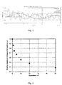
- Fig. 3 schematically illustrates voltage difference between nodes 23 and 24 as a function of time (with 1.2-50 unit impulse on winding terminal B), for three different values of the external capacitance C ext,1 .
- Fig. 3 shows the effect which the addition of different amounts of external capacitance (C ext,1 ) has on the time-dependent voltage difference over the "open end" between node 23 at the first intermediate end point C (i.e., the open end of the regulating winding) and node 24 at the second intermediate end point D (i.e., the tap selector contact), calculated with the same model as used for the simulation results shown in Fig 2 .
- C ext,1 5-10 nF. It is not expected It is not expected that the power and voltage ratings of the transformer will have a large impact on these values; in contrast, the voltage rating of the external capacitor C ext,1 will increase with that of the transformer.
- Fig. 4 shows the ratio of the maximum over-voltage over the "open end" for different capacitance values.
- Fig. 4 shows results from measurements on a smaller transformer (24 kV / 900 kVA) of the same design type (VCC) as above.
- a winding arrangement with an "open end” similar to the one shown in Fig. 3 is provided in one of the windings.
- To observe transient over-voltages over the gap 33% of the total number of turns of the winding were bypassed by a galvanic tap changer.
- Fig. 4 shows the ratio of the maximum voltage for each external capacitance value to the reference without external capacitance ("o nF"). As can be seen, with high enough capacitance value a significant reduction of the maximum overvoltage was achieved.
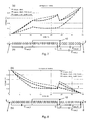
- the external passive electric component is an external capacitor C ext,2 connected to the winding between the first intermediate end point C and the second winding terminal B. This is illustrated in Fig. 5 .
- an external capacitor is thus connected between the open end of the regulating winding and the second winding terminal B at which the impulse is applied.
- the capacitance value, C ext,2 is determined such that the voltage deviation between the "capacitive” and “inductive” distributions is minimized.
- the bottom part (b) of Fig. 5 schematically illustrates a first conductor of the winding extending from a first winding terminal A to a first intermediate end point C and a second conductor of the winding extending from a second intermediate end point D to a second winding terminal B.
- winding sections or discs are represented by rectangles.
- dots On the connections between subsequent discs lie the "nodes" of the model, indicated by dots, which are the points along the winding where the voltage was calculated with the simulation model for the result shown in the top part (a) of Fig. 5 .
- an external capacitor C ext,2 is connected to the winding between nodes 23 and 34.
- Fig. 6 schematically illustrates voltage difference between nodes 23 and 34 as a function of time (with 1.2-50 unit impulse on winding terminal B), for three different values of the external capacitance C ext,2 .
- Fig. 6 shows the effect of the external capacitances on the time-dependent voltage difference the "open end" between node 23 at the first intermediate end point C (i.e., the open end of the regulating winding) and node 34 at the second intermediate end point D (i.e., the tap selector contact), calculated with the same model.
- the capacitance value should be well adjusted to the particular winding design (i.e., it must neither be too small nor too large) in order to achieve maximum benefit.
- the needed capacitance value is quite low, but the voltage rating of the capacitor is of the same order as the impulse magnitude, so that in practice a series connection of capacitors may be used.
- a series of capacitors C ext,2 connected to the winding between the first intermediate end point C and the second winding terminal B.
- the necessary voltage rating of the capacitor (or capacitors in series) may be reduced by moving the regulating winding relative to the main winding, so that it lies electrically closer to winding terminal B.
- the present configuration may only work when the impulse hits the windings from winding terminal B and not winding terminal A. Therefore, the present configuration may not be suitable in this form for ⁇ -connected phase windings; but it may be suitable for Y-connected windings with the neutral at terminal A.
- the present configuration may be modified by "pinning" the potential of the tap selector contact somewhere in the middle between the two terminal voltages through a capacitive voltage divider.
- the transformer arrangement thus further comprises an external capacitive voltage divider connected to the first winding terminal A, the second intermediate end point D, and the second winding terminal B. This is illustrated in the bottom parts (b) of Figs. 7 and 8 .
- the external capacitive voltage divider may comprise a capacitor C ext,3 connected to the winding between the first winding terminal A and the second intermediate end point D and a capacitor C ext,4 connected to the winding between the second intermediate end point D and the second winding terminal B.
- This embodiment thus requires three capacitors with full impulse voltage rating.
- the surge capacitance of the winding may be significantly increased (ca. 500 pF instead of 120 pF without capacitors in the present example), which may be desirable in some applications and undesirable in others.
- the top part (a) of Fig. 7 shows the final “inductive” and the initial “capacitive” impulse voltage distributions along the winding for a unit impulse amplitude, obtained with a simulation model for a foil-disc winding of a 10 MVA transformer of VCC type for an impulse applied on winding terminal B, with and without external capacitors C ext,2 , C ext,3 and C ext,4 .
- the bottom part (b) of Fig. 7 schematically illustrates a first conductor of the winding extending from a first winding terminal A to a first intermediate end point C and a second conductor of the winding extending from a second intermediate end point D to a second winding terminal B.
- a first conductor of the winding extending from a first winding terminal A to a first intermediate end point C
- a second conductor of the winding extending from a second intermediate end point D to a second winding terminal B.
- winding sections or discs are represented by rectangles.
- the "nodes" of the model indicated by dots, which are the points along the winding where the voltage was calculated with the simulation model for the result shown in the top part (a) of Fig. 7 .
- an external capacitor C ext,2 is connected to the winding between nodes 23 and 34
- an external capacitor C ext,3 is connected to the winding between nodes 1 and 24
- an external capacitor C ext,4 is connected to the winding between nodes 24 and 34.
- the top part (a) of Fig. 8 shows the final “inductive” and the initial “capacitive” impulse voltage distributions along the winding for a unit impulse amplitude, obtained with a simulation model for a foil-disc winding of a 10 MVA transformer of VCC type for an impulse applied on winding terminal A, with and without external capacitors C ext,2 , C ext,3 and C ext,4 .
- the bottom part (b) of Fig. 8 schematically illustrates a first conductor of the winding extending from a first winding terminal A to a first intermediate end point C and a second conductor of the winding extending from a second intermediate end point D to a second winding terminal B.
- a first conductor of the winding extending from a first winding terminal A to a first intermediate end point C
- a second conductor of the winding extending from a second intermediate end point D to a second winding terminal B.
- winding sections or discs are represented by rectangles.
- the "nodes" of the model indicated by dots, which are the point along the winding where the voltage was calculated with the simulation model for the result shown in the top part (a) of Fig. 8 .
- an external capacitor C ext,2 is connected to the winding between nodes 23 and 34
- an external capacitor C ext,3 is connected to the winding between nodes 1 and 24
- an external capacitor C ext,4 is connected to the winding between nodes 24 and 34.
- the power and voltage ratings are not expected to have a very large impact on these values, whereas the voltage rating of the capacitor will increase with that of the transformer.
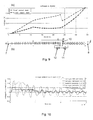
- the electronic component is an external varistor 11 connected to the winding between the first intermediate end point C and the second intermediate end point D. This is illustrated in Fig. 9 . Connecting an external varistor 11 over the open part of the regulating winding effectively limits the oscillation amplitude to the varistor protection level.
- Fig. 9 shows the final "inductive” distribution and the initial “capacitive” distribution for a unit impulse amplitude, obtained with a simulation model for the foil-disc winding of a 10 MVA unit of VCC type.
- the top part (a) of Fig. 9 shows the final “inductive” and the initial “capacitive” impulse voltage distributions along the winding for a unit impulse amplitude, obtained with a simulation model for a foil-disc winding of a 10 MVA transformer of VCC type for an impulse applied on winding terminal B, with an external varistor 11 and an external fuse 12.
- the bottom part (b) of Fig. 9 schematically illustrates a first conductor of the winding extending from a first winding terminal A to a first intermediate end point C and a second conductor of the winding extending from a second intermediate end point D to a second winding terminal B.
- winding sections or discs are represented by rectangles.
- nodes On the connections between subsequent discs lie the "nodes" of the model, indicated by dots, which are the points along the winding where the voltage was calculated with the simulation model for the result shown in the top part (a) of Fig. 9 .
- dots In the bottom part (b) of Fig. 5 an external varistor and an optional external fuse are connected in series to the winding between nodes 23 and 34.
- Fig. 10 schematically illustrates voltage difference between nodes 23 and 24 as a function of time (with 1.2-50 unit impulse on winding terminal B), for two different values of the external varistor 11.
- Fig. 10 shows the effect which the addition of an external varistor has on the time-dependent voltage difference over the "open end" between node 23 at the first intermediate end point C (i.e., the open end of the regulating winding) and node 24 at the second intermediate end point D (i.e., the tap selector contact), calculated with the same model as used for the simulation results shown in Fig 9 .
- the varistor protection level can be adjusted, for instance to the requirements of the tap changer.
- the external varistor 11 has a protection level of 5-30% of the transformer basic insulation level, BIL.
- the energy W arr dumped into the varistor is typically of the order of some Joule for 100 kV impulse magnitude.
- the following is obtained:
- an external fuse 12 is connected in series with the external varistor 11.
- a fuse 12 connected in series with the varistor 11 could protect the transformer in case of varistor breakdown. Its dimensioning is determined based on the expected "normal" varistor current under impulse conditions being low (below 10 A per 100 kV impulse magnitude in the present example, see Fig. 10 ).
- the varistor current during impulse is of the order of some Amps, i.e., much smaller than a short circuit current.
- the embodiments are particularly suitable for dry transformers.
- the disclosed transformer is a dry transformer. Dry distribution transformers may be used to step down three-phase medium voltage to low voltage for power distribution. Such transformers are used primarily in metropolitan areas (public buildings, offices, distribution substations) and are also used in industrial applications. Dry type transformers are an ideal solution for applications where the transformers have to be installed near their place of use.
- Dry type transformers are environmentally safe and suitable for indoor and outdoor applications. They provide excellent mechanical and short circuit strength, have no liquids to leak, and present no danger of fire or explosion.
- the transformers may or may not be provided with enclosures for extra added protection against harsh outdoor or indoor environments. They can be used in all types of applications including ground mount, primary and secondary substation units.
Landscapes
- Engineering & Computer Science (AREA)
- Power Engineering (AREA)
- Regulation Of General Use Transformers (AREA)
- Coils Of Transformers For General Uses (AREA)
- Coils Or Transformers For Communication (AREA)
Description
- Embodiments presented herein relate to a transformer arrangement, and in particular to a transformer arrangement for mitigating transient voltage oscillations.
- In general terms, a transformer is a power converter that transfers alternating current (AC) electrical energy through inductive coupling between circuits of the transformer's windings.
- Dry-type transformers are typically used for voltages up to 36 kV. They are mostly equipped with off-load tap changers allowing to set five different voltage ratios and a range of +/-5%. On-load tap changers are rarely used with dry-type transformers. Currently the application range of dry type transformer designs is being extended, involving a significant increase of their voltage rating. At this voltage levels most applications require the use of an on-load tap changer (OLTC) with much larger regulation range (+/-20%) and number of steps, as well as a corresponding extended regulation winding.
- In the oil and gas industry, electric motors are used to drive submersible pumps which are located down in an oil or gas well. Such a motor is typically energized through a transformer connected at the well site to a conventional power distribution network.
- Dry-type transformers have been operated at low voltage levels and with a small regulation range; in this case the voltages related to the transient oscillations can easily be managed and require relatively small dielectric distances. However, with increasing voltage and regulation range, the insulation distances grow and larger and larger dimensions are required also for the OLTC. Particularly, during impulse tests, transient oscillations are excited in the regulating winding of dry type transformers, which lead to high electric stresses on the OLTC. These stresses are particularly pronounced for a simple linear tap changer concept and when the OLTC is in the minimum position, so that the whole regulating winding is open (i.e., connected to the main winding at one end only).
- Hence, there is still a need for an improved transformer arrangement for mitigating transient voltage oscillations.
- An object of embodiments herein is to provide improved transformer arrangement for mitigating transient voltage oscillations.
- According to a first aspect there is presented a transformer arrangement for mitigating transient voltage oscillations, comprising: a transformer, the transformer comprising: a transformer core comprising at least one core leg; and a winding wound around one of the at least one core leg, the winding extending from a first winding terminal to a second winding terminal and comprising a first winding section along a first conductor extending from the first winding terminal to a first intermediate end point, and a second winding section along a second conductor extending from a second intermediate end point to the second winding terminal. The transformer arrangement further comprises an external passive electric component connected between the first intermediate end point and either the second intermediate end point or the second winding terminal arranged to decrease an effective difference between capacitive and inductive voltage distributions between the intermediate end points such that transient voltage oscillations in the winding are mitigated.
- Advantageously, the behaviour of the transformer under normal operating conditions is not affected by the connected external passive electric component.
- Advantageously, according to some embodiments the arrangement works equally well for impulse applied on either winding terminal. Advantageously, according to some embodiments the surge capacitance of the transformer as a whole is not significantly affected.
- According to one embodiment the external passive electric component is an external capacitor Cext,1 connected to the winding between the first intermediate end point and the second intermediate end point. Advantageously, such an arrangement works equally well for impulse applied on either winding terminal. Advantageously, the needed voltage rating of the capacitors is significantly lower than the impulse magnitude (by a factor 0.20-0.3). Thereby a series connection of capacitors may be avoided.
- According to one embodiment the external passive electric component is an external capacitor Cext,2 connected to the winding between the first intermediate end point and the second winding terminal. Advantageously, the needed voltage rating of the capacitors is significantly lower than the impulse magnitude (by a factor 0.20-0.3). Thereby a series connection of capacitors may be avoided.
- According to one embodiment the external passive electric component is an external varistor connected to the winding between the first intermediate end point and the second intermediate end point. Advantageously, such a transformer arrangement works equally well for impulse applied on either winding terminal.
- According to one embodiment the transformer arrangement further comprises a plurality of tap changer contacts provided along the first conductor. Advantageously, connecting an external passive electric component presents no practical problems in such a transformer arrangement since all tap changer contacts are easily accessible from the outside of the transformer.
- According to a second aspect there is presented a transformer arrangement for mitigating transient voltage oscillations, comprising: a transformer, the transformer comprising: a transformer core comprising at least one core leg; and a winding wound around one of the at least one core leg, the winding extending from a first winding terminal to a second winding terminal and comprising a first winding section along a first conductor extending from the first winding terminal to a first intermediate end point, and a second winding section along a second conductor extending from a second intermediate end point to the second winding terminal. The transformer arrangement further comprises an external capacitor Cext,1 connected to the winding between the first intermediate end point and the second intermediate end point; or an external capacitor Cext,2 connected to the winding between the first intermediate end point and the second winding terminal; or an external varistor connected to the winding between the first intermediate end point and the second intermediate end point.
- Advantageously, the behaviour of the transformer under normal operating conditions is not affected by the connected one or more external capacitors or varistors.
- Advantageously, the needed voltage rating of the capacitors is significantly lower than the impulse magnitude (by a factor 0.20-0.3). Thereby a series connection of capacitors may be avoided.
- According to one embodiment the transformer of the first aspect and/ or the second aspect is a dry transformer.
- It is to be noted that any feature of the first and second aspects may be applied to any other aspect, wherever appropriate. Likewise, any advantage of the first aspect may equally apply to the second aspect, respectively, and vice versa. Other objectives, features and advantages of the enclosed embodiments will be apparent from the following detailed disclosure, from the attached dependent claims as well as from the drawings.
- Generally, all terms used in the claims are to be interpreted according to their ordinary meaning in the technical field, unless explicitly defined otherwise herein. All references to "a/an/the element, apparatus, component, means, step, etc." are to be interpreted openly as referring to at least one instance of the element, apparatus, component, means, step, etc., unless explicitly stated otherwise. The steps of any method disclosed herein do not have to be performed in the exact order disclosed, unless explicitly stated.
- The invention is now described, by way of example, with reference to the accompanying drawings, in which:
-
Fig. 1 is a schematic illustration (partly as a cross-section view) of a transformer arrangement according to embodiments; -
Fig. 2 schematically illustrates the final "inductive" and the initial "capacitive" impulse voltage distributions along the HV winding according to an embodiment; -
Fig. 3 schematically illustrates voltage as a function of time; -
Fig. 4 shows the ratio of the maximum over-voltage over the "open end" for different capacitance values inFig. 2 ; -
Fig. 5 schematically illustrates the final "inductive" and the initial "capacitive" impulse voltage distributions along the HV winding according to an embodiment; -
Fig. 6 schematically illustrates voltage as a function of time for the embodiment inFig. 5 ; -
Fig. 7 schematically illustrates the final "inductive" and the initial "capacitive" impulse voltage distributions along the HV winding according to an embodiment; -
Fig. 8 schematically illustrates the final "inductive" and the initial "capacitive" impulse voltage distributions along the HV winding according to an embodiment; -
Fig. 9 schematically illustrates the final "inductive" and the initial "capacitive" impulse voltage distributions along the HV winding according to an embodiment; and -
Fig. 10 schematically illustrates voltage and arrester current as a function of time for the embodiment inFig. 9 . - The inventive concepts will now be described more fully hereinafter with reference to the accompanying drawings, in which certain embodiments of are shown. The inventive concepts may, however, be embodied in many different forms and should not be construed as limited to the embodiments set forth herein; rather, these embodiments are provided by way of example so that this disclosure will be thorough and complete, and will fully convey the scope of the inventive concepts to those skilled in the art. Like numbers refer to like elements throughout the description.
- The inventive concepts present different ways to mitigate transient stresses in transformers by connecting an external element to the windings of a transformer as described in more detail with reference to the below disclosed embodiments. As a result thereof, the voltage difference between the (previously open) winding ends is reduced.
-
Fig. 1 schematically illustrates a possible winding geometry of atransformer arrangement 1 according to embodiments. Thetransformer arrangement 1 comprises a transformer. The transformer comprises atransformer core 2. Thetransformer core 2 comprises at least one core leg. According to the embodiment illustrated inFig. 1 thetransformer core 2 comprises threecore legs core legs - The winding extends from a first winding terminal A to a second winding terminal B. The winding comprises a first winding section. The first winding section is provided as a set of winding discs 6. The winding further comprises a second winding section. The second winding section is provided as a set of winding discs 6. As the skilled person understands, the total numbers of winding discs 6 or sections and of regulating-winding taps may vary depending on the actual implementation and environment of the
transformer arrangement 1. - The winding may be denoted a first winding. According to some embodiments the transformer arrangement further comprises a second winding. According to embodiments the second winding is wound between the first winding and the one core leg. The first winding may represent a primary high voltage, HV, winding and the second winding represents a secondary low voltage, LV, winding. Hence, according to one embodiment a secondary low voltage (LV) winding 4a, 4b, 4c is wound around each one of the
core legs - As further disclosed below, for example with references to
Figs. 2 ,5 and9 , the first winding section is provided along afirst conductor 7 and the second winding section is provided along asecond conductor 8. The first conductor extends from the first winding terminal A to a first intermediate end point C. The second conductor extends from a second intermediate end point D to the second winding terminal B. - The
transformer arrangement 1 further comprises a plurality oftap changer contacts 9. Thetap changer contacts 9 are provided along thefirst conductor 7. In general terms, atap changer contact 9 is a connection point along a transformer winding that allows a certain number of turns (windings) to be selected. This provides a transformer with a variable turns ratio, thereby enabling voltage regulation of the output. The tap selection is made via atap changer 10. - During operation of the
transformer arrangement 1 the initial "capacitive" voltage distribution at least along the winding 5a, 5b, 5c, determined solely by its stray capacitances, is different from the "inductive", quasi-stationary distribution at later times, determined by the stray inductances. This difference leads to voltage oscillations during the dynamic transition between the two. Thetransformer arrangement 1 is arranged to mitigating such transient voltage oscillations. In order to do so thetransformer arrangement 1 comprises an external passive electric component. The external passive electric component is dimensioned so as to decrease an effective difference between capacitive and inductive voltage distributions between the intermediate end points such that transient voltage oscillations in the winding are mitigated. As further disclosed below, for example with references toFigs. 2 and9 , the external passive electric component may be connected between the first intermediate end point C and the second intermediate end point D. As further disclosed below, for example with references toFig. 5 , the external passive electric component may be connected between the first intermediate end point C and the second winding terminal B. - According to exemplary embodiments either an external capacitor is connected over the open part of the regulating winding, or an external capacitor is connected between the open end of the regulating winding and the terminal B at which the impulse is applied, or an external varistor is connected over the open part of the regulating winding. These embodiments will now be described in turn. The "open end" is herein defined as the conductor-less part extending between the first conductor and the second conductor, i.e. between the first intermediate end point C and the second intermediate end point D.
- According to one embodiment the external passive electric component is an external capacitor Cext,1 connected to the winding 5a, 5b, 5c between the first intermediate end point C and the second intermediate end point D. This is illustrated in
Fig. 2 . - Connecting an external capacitor over the open part of the regulating winding increases the oscillation period (i.e. reduces the oscillation frequency) to such an extent that the impulse decays before the oscillation reaches its first maximum, thereby decreasing the effective difference between "capacitive" and "inductive" voltage distributions. This is illustrated in
Fig 3 , see below. - The top part (a) of
Fig. 2 shows the final "inductive" and the initial "capacitive" impulse voltage distributions along the winding for a unit impulse amplitude, obtained with a simulation model for a foil-disc winding of a 10 MVA transformer of VCC type for an impulse applied on winding terminal B. The bottom part (b) ofFig. 2 schematically illustrates a first conductor of the winding extending from a first winding terminal A to a first intermediate end point C and a second conductor of the winding extending from a second intermediate end point D to a second winding terminal B. In the bottom part (b) ofFig. 2 , the winding sections or discs 6 ofFig. 1 are represented by rectangles. On the connections between subsequent discs lie the "nodes" of the model, indicated by dots, which are the points along the winding where the voltage was calculated with the simulation model for the result shown in the top part (a) ofFig. 2 . In the bottom part (b) ofFig. 2 an external capacitor Cext,1 is connected to the winding betweennodes -
Fig. 3 schematically illustrates voltage difference betweennodes Fig. 3 shows the effect which the addition of different amounts of external capacitance (Cext,1) has on the time-dependent voltage difference over the "open end" betweennode 23 at the first intermediate end point C (i.e., the open end of the regulating winding) andnode 24 at the second intermediate end point D (i.e., the tap selector contact), calculated with the same model as used for the simulation results shown inFig 2 . - According to an embodiment the capacitance value is in the range Cext,1 = 5-100 nF. Preferably Cext,1 = 5-10 nF. It is not expected It is not expected that the power and voltage ratings of the transformer will have a large impact on these values; in contrast, the voltage rating of the external capacitor Cext,1 will increase with that of the transformer.
-
Fig. 4 shows the ratio of the maximum over-voltage over the "open end" for different capacitance values.Fig. 4 shows results from measurements on a smaller transformer (24 kV / 900 kVA) of the same design type (VCC) as above. For these measurements, a winding arrangement with an "open end" similar to the one shown inFig. 3 is provided in one of the windings. To observe transient over-voltages over the gap, 33% of the total number of turns of the winding were bypassed by a galvanic tap changer. First the transient voltage over the "open end" was measured and its maximum was recorded as the reference value (the data point labelled "0 nF" inFig. 3 ). Then, external capacitors, Cext,1, with different capacitance values were connected over the "open end", and the transient voltages over the gap were measured in each case.Fig. 4 shows the ratio of the maximum voltage for each external capacitance value to the reference without external capacitance ("o nF"). As can be seen, with high enough capacitance value a significant reduction of the maximum overvoltage was achieved. These results are consistent with the simulations on the 10 MVA design shown inFig. 3 . - According to one embodiment the external passive electric component is an external capacitor Cext,2 connected to the winding between the first intermediate end point C and the second winding terminal B. This is illustrated in
Fig. 5 . According to a second embodiment an external capacitor is thus connected between the open end of the regulating winding and the second winding terminal B at which the impulse is applied. - The capacitance value, Cext,2, is determined such that the voltage deviation between the "capacitive" and "inductive" distributions is minimized.
- The top part (a) of
Fig. 5 shows the final "inductive" and the initial "capacitive" impulse voltage distributions along the winding for a unit impulse amplitude, obtained with a simulation model for a foil-disc winding of a 10 MVA transformer of VCC type for an impulse applied on winding terminal B, for two capacitance values Cext,2 = 0.5 nF and Cext,2 = 0.6 nF determined to be close to the optimum. The bottom part (b) ofFig. 5 schematically illustrates a first conductor of the winding extending from a first winding terminal A to a first intermediate end point C and a second conductor of the winding extending from a second intermediate end point D to a second winding terminal B. In the bottom part (b) ofFig. 5 , winding sections or discs are represented by rectangles. On the connections between subsequent discs lie the "nodes" of the model, indicated by dots, which are the points along the winding where the voltage was calculated with the simulation model for the result shown in the top part (a) ofFig. 5 . In the bottom part (b) ofFig. 5 an external capacitor Cext,2 is connected to the winding betweennodes -
Fig. 6 schematically illustrates voltage difference betweennodes Fig. 6 shows the effect of the external capacitances on the time-dependent voltage difference the "open end" betweennode 23 at the first intermediate end point C (i.e., the open end of the regulating winding) andnode 34 at the second intermediate end point D (i.e., the tap selector contact), calculated with the same model. - The capacitance value should be well adjusted to the particular winding design (i.e., it must neither be too small nor too large) in order to achieve maximum benefit. According to an embodiment he capacitance value is in the range Cext,2 = 0.1-2.0 nF, preferably Cext,2 = 0.1-1.0 nF, more preferably Cext,2 = 0.5-0.6 nF. It is not expected that the power and voltage ratings have a very large impact on these values; in contrast, the voltage rating of the capacitor will increase with that of the transformer.
- The needed capacitance value is quite low, but the voltage rating of the capacitor is of the same order as the impulse magnitude, so that in practice a series connection of capacitors may be used. According to an embodiment there is thus provided a series of capacitors Cext,2 connected to the winding between the first intermediate end point C and the second winding terminal B. The necessary voltage rating of the capacitor (or capacitors in series) may be reduced by moving the regulating winding relative to the main winding, so that it lies electrically closer to winding terminal B.
- The present configuration may only work when the impulse hits the windings from winding terminal B and not winding terminal A. Therefore, the present configuration may not be suitable in this form for Δ-connected phase windings; but it may be suitable for Y-connected windings with the neutral at terminal A.
- For Δ-connected phase windings the present configuration may be modified by "pinning" the potential of the tap selector contact somewhere in the middle between the two terminal voltages through a capacitive voltage divider. According to an embodiment the transformer arrangement thus further comprises an external capacitive voltage divider connected to the first winding terminal A, the second intermediate end point D, and the second winding terminal B. This is illustrated in the bottom parts (b) of
Figs. 7 and 8 . - Thus, the external capacitive voltage divider may comprise a capacitor Cext,3 connected to the winding between the first winding terminal A and the second intermediate end point D and a capacitor Cext,4 connected to the winding between the second intermediate end point D and the second winding terminal B. This embodiment thus requires three capacitors with full impulse voltage rating. Also, the surge capacitance of the winding may be significantly increased (ca. 500 pF instead of 120 pF without capacitors in the present example), which may be desirable in some applications and undesirable in others.
- The top part (a) of
Fig. 7 shows the final "inductive" and the initial "capacitive" impulse voltage distributions along the winding for a unit impulse amplitude, obtained with a simulation model for a foil-disc winding of a 10 MVA transformer of VCC type for an impulse applied on winding terminal B, with and without external capacitors Cext,2, Cext,3 and Cext,4. The bottom part (b) ofFig. 7 schematically illustrates a first conductor of the winding extending from a first winding terminal A to a first intermediate end point C and a second conductor of the winding extending from a second intermediate end point D to a second winding terminal B. In the bottom part (b) ofFig. 7 , winding sections or discs are represented by rectangles. On the connections between subsequent discs lie the "nodes" of the model, indicated by dots, which are the points along the winding where the voltage was calculated with the simulation model for the result shown in the top part (a) ofFig. 7 . In the bottom part (b) ofFig. 7 an external capacitor Cext,2 is connected to the winding betweennodes nodes nodes - The top part (a) of
Fig. 8 shows the final "inductive" and the initial "capacitive" impulse voltage distributions along the winding for a unit impulse amplitude, obtained with a simulation model for a foil-disc winding of a 10 MVA transformer of VCC type for an impulse applied on winding terminal A, with and without external capacitors Cext,2, Cext,3 and Cext,4. The bottom part (b) ofFig. 8 schematically illustrates a first conductor of the winding extending from a first winding terminal A to a first intermediate end point C and a second conductor of the winding extending from a second intermediate end point D to a second winding terminal B. In the bottom part (b) ofFig. 8 , winding sections or discs are represented by rectangles. On the connections between subsequent discs lie the "nodes" of the model, indicated by dots, which are the point along the winding where the voltage was calculated with the simulation model for the result shown in the top part (a) ofFig. 8 . In the bottom part (b) ofFig. 8 an external capacitor Cext,2 is connected to the winding betweennodes nodes nodes - The capacitance value for Δ-connected phase windings is preferably in the range 0.1-2.0 nF. That is, according to embodiments Cext,3 = 0.1-2.0 nF and Cext,4 = 0.1-2.0 nF, and preferably Cext,3 = Cext,4 = 1.0 nF. As above, the power and voltage ratings are not expected to have a very large impact on these values, whereas the voltage rating of the capacitor will increase with that of the transformer.
- According to one embodiment the electronic component is an
external varistor 11 connected to the winding between the first intermediate end point C and the second intermediate end point D. This is illustrated inFig. 9 . Connecting anexternal varistor 11 over the open part of the regulating winding effectively limits the oscillation amplitude to the varistor protection level. - The top part of
Fig. 9 shows the final "inductive" distribution and the initial "capacitive" distribution for a unit impulse amplitude, obtained with a simulation model for the foil-disc winding of a 10 MVA unit of VCC type. - The top part (a) of
Fig. 9 shows the final "inductive" and the initial "capacitive" impulse voltage distributions along the winding for a unit impulse amplitude, obtained with a simulation model for a foil-disc winding of a 10 MVA transformer of VCC type for an impulse applied on winding terminal B, with anexternal varistor 11 and anexternal fuse 12. The bottom part (b) ofFig. 9 schematically illustrates a first conductor of the winding extending from a first winding terminal A to a first intermediate end point C and a second conductor of the winding extending from a second intermediate end point D to a second winding terminal B. In the bottom part (b) ofFig. 9 , winding sections or discs are represented by rectangles. On the connections between subsequent discs lie the "nodes" of the model, indicated by dots, which are the points along the winding where the voltage was calculated with the simulation model for the result shown in the top part (a) ofFig. 9 . In the bottom part (b) ofFig. 5 an external varistor and an optional external fuse are connected in series to the winding betweennodes -
Fig. 10 schematically illustrates voltage difference betweennodes external varistor 11. In more detail,Fig. 10 shows the effect which the addition of an external varistor has on the time-dependent voltage difference over the "open end" betweennode 23 at the first intermediate end point C (i.e., the open end of the regulating winding) andnode 24 at the second intermediate end point D (i.e., the tap selector contact), calculated with the same model as used for the simulation results shown inFig 9 . - The varistor protection level can be adjusted, for instance to the requirements of the tap changer. According to an embodiment the
external varistor 11 has a protection level of 5-30% of the transformer basic insulation level, BIL. - The energy Warr dumped into the varistor is typically of the order of some Joule for 100 kV impulse magnitude. For example, for the 10 MVA VCC type transformer model used above the following is obtained:
- Warr = (5.9 J)(Uimp/100 kV)2 for varistor protection level = 0.1Uimp, and
- Warr = (1.7 J)(Uimp/100 kV)2 for varistor protection level = 0.2Uimp,
- where Uimp is the impulse voltage maximum.
- According to embodiments an
external fuse 12 is connected in series with theexternal varistor 11. Afuse 12 connected in series with thevaristor 11 could protect the transformer in case of varistor breakdown. Its dimensioning is determined based on the expected "normal" varistor current under impulse conditions being low (below 10 A per 100 kV impulse magnitude in the present example, seeFig. 10 ). The varistor current during impulse is of the order of some Amps, i.e., much smaller than a short circuit current. - The invention has mainly been described above with reference to a few embodiments. However, as is readily appreciated by a person skilled in the art, other embodiments than the ones disclosed above are equally possible within the scope of the invention, as defined by the appended patent claims. For example, the embodiments are particularly suitable for dry transformers. According to embodiments the disclosed transformer is a dry transformer. Dry distribution transformers may be used to step down three-phase medium voltage to low voltage for power distribution. Such transformers are used primarily in metropolitan areas (public buildings, offices, distribution substations) and are also used in industrial applications. Dry type transformers are an ideal solution for applications where the transformers have to be installed near their place of use. Close installation saves on the installation outlay of cabling while at the same time reducing losses in cables and terminals on the low-voltage side. Dry type transformers are environmentally safe and suitable for indoor and outdoor applications. They provide excellent mechanical and short circuit strength, have no liquids to leak, and present no danger of fire or explosion. The transformers may or may not be provided with enclosures for extra added protection against harsh outdoor or indoor environments. They can be used in all types of applications including ground mount, primary and secondary substation units.
- However, the embodiments presented herein are neither specific to dry-type transformers nor to a simple linear tap changer concept. The embodiments presented herein are also applicable to for oil-filled transformers and more complex tap changer concepts.
Claims (15)
- A transformer arrangement (1) for mitigating transient voltage oscillations, comprising:a transformer, the transformer comprising:a transformer core (2) comprising at least one core leg (3a, 3b, 3c); anda winding (4a, 4b, 4c, 5a, 5c, 5d) wound around each one of the at least one core leg, the winding extending from a first winding terminal (A) to a second winding terminal (B) and comprising a first winding section along a first conductor (7) extending from said first winding terminal (A) to a first intermediate end point (C), and a second winding section along a second conductor (8) extending from a second intermediate end point (D) to said second winding terminal (B); andan external passive electric component (Cext,1, Cext,2,11) connected between the first intermediate end point (C) and either the second intermediate end point (D) or said second winding terminal (B) arranged to decrease an effective difference between capacitive and inductive voltage distributions between the intermediate end points such that transient voltage oscillations in the winding are mitigated.
- The transformer arrangement according to claim 1, wherein the external passive electric component is an external capacitor Cext,1 connected to the winding between said first intermediate end point (C) and said second intermediate end point (D).
- The transformer arrangement according to claim 2, wherein Cext,1 = 5-100 nF, preferably Cext,1 = 5-10 nF.
- The transformer arrangement according to claim 1, wherein the external passive electric component is an external capacitor Cext,2 connected to the winding between said first intermediate end point (C) and said second winding terminal (B).
- The transformer arrangement according to claim 4, wherein Cext,2 = 0.1-2.0 nF.
- The transformer arrangement according to claim 4 or 5, further comprising:an external capacitive voltage divider (Cext 3, Cext4) connected to said first winding terminal (A), said second intermediate end point (D), and said second winding terminal (B).
- The transformer arrangement according to claim 6, wherein said external capacitive voltage divider comprises:a capacitor Cext,3 connected to the winding between said first winding terminal (A) and said second intermediate end point (D); anda capacitor Cext,4 connected to the winding between said second intermediate end point (D) and said second winding terminal (B).
- The transformer arrangement according to claim 7, wherein Cext,3 = 0.1-2.0 nF and Cext,4 = 0.1-2.0 nF, and wherein preferably Cext,3 = Cext,4 = 1.0 nF.
- The transformer arrangement according to claim 1, wherein the electronic component is an external varistor (11) connected to the winding between said first intermediate end point (C) and said second intermediate end point (D).
- The transformer arrangement according to claim 9, wherein the external varistor has a protection level of 5-30% of the transformer basic insulation level, BIL.
- The transformer arrangement according to claim 9 or 10, further comprising:an external fuse (12) connected in series with the external varistor.
- The transformer arrangement according to any one of the preceding claims, further comprising:a plurality of tap changer contacts (9) provided along said first conductor.
- The transformer arrangement according to claim 12, further comprising:a tap changer (10) connectable to the winding at said second intermediate end point (D) and a point (E) along said first conductor at one of said plurality of tap changer contacts.
- The transformer arrangement according to any one of the preceding claims, wherein said winding is denoted a first winding, the transformer arrangement further comprising:a second winding wound either between said first winding and said one core leg, or along a circumference of said first winding.
- The transformer arrangement according to any one of the preceding claims, wherein the transformer is a dry transformer.
Priority Applications (8)
| Application Number | Priority Date | Filing Date | Title |
|---|---|---|---|
| ES12198162.5T ES2563109T3 (en) | 2012-12-19 | 2012-12-19 | Transformer arrangement to mitigate transient voltage oscillations |
| PL12198162T PL2747098T3 (en) | 2012-12-19 | 2012-12-19 | Transformer arrangement for mitigating transient voltage oscillations |
| EP12198162.5A EP2747098B1 (en) | 2012-12-19 | 2012-12-19 | Transformer arrangement for mitigating transient voltage oscillations |
| US14/652,692 US9953760B2 (en) | 2012-12-19 | 2013-11-19 | Transformer arrangement for mitigating transient voltage oscillations |
| BR112015014196-0A BR112015014196B1 (en) | 2012-12-19 | 2013-11-19 | transformer arrangement to mitigate transient voltage fluctuations |
| PCT/EP2013/074165 WO2014095206A1 (en) | 2012-12-19 | 2013-11-19 | Transformer arrangement for mitigating transient voltage oscillations |
| KR1020157018588A KR101591235B1 (en) | 2012-12-19 | 2013-11-19 | Transformer arrangement for mitigating transient voltage oscillations |
| CN201380066897.1A CN104871267B (en) | 2012-12-19 | 2013-11-19 | For mitigating the transformer arrangement of instantaneous voltage vibration |
Applications Claiming Priority (1)
| Application Number | Priority Date | Filing Date | Title |
|---|---|---|---|
| EP12198162.5A EP2747098B1 (en) | 2012-12-19 | 2012-12-19 | Transformer arrangement for mitigating transient voltage oscillations |
Publications (2)
| Publication Number | Publication Date |
|---|---|
| EP2747098A1 EP2747098A1 (en) | 2014-06-25 |
| EP2747098B1 true EP2747098B1 (en) | 2015-12-16 |
Family
ID=47429650
Family Applications (1)
| Application Number | Title | Priority Date | Filing Date |
|---|---|---|---|
| EP12198162.5A Active EP2747098B1 (en) | 2012-12-19 | 2012-12-19 | Transformer arrangement for mitigating transient voltage oscillations |
Country Status (8)
| Country | Link |
|---|---|
| US (1) | US9953760B2 (en) |
| EP (1) | EP2747098B1 (en) |
| KR (1) | KR101591235B1 (en) |
| CN (1) | CN104871267B (en) |
| BR (1) | BR112015014196B1 (en) |
| ES (1) | ES2563109T3 (en) |
| PL (1) | PL2747098T3 (en) |
| WO (1) | WO2014095206A1 (en) |
Families Citing this family (6)
| Publication number | Priority date | Publication date | Assignee | Title |
|---|---|---|---|---|
| ES2563109T3 (en) | 2012-12-19 | 2016-03-10 | Abb Research Ltd. | Transformer arrangement to mitigate transient voltage oscillations |
| US9882373B2 (en) * | 2014-11-21 | 2018-01-30 | Abb Schweiz Ag | System for protection of dry type transformers |
| DK3528266T3 (en) * | 2018-02-15 | 2021-01-04 | Abb Power Grids Switzerland Ag | INSULATION OF NON-LIQUID SUBMITTED TRANSFORMERS |
| RU2688882C1 (en) * | 2018-08-27 | 2019-05-23 | Федеральное государственное бюджетное образовательное учреждение высшего образования "Вятский государственный университет" (ВятГУ) | Controlled shunt reactor-autotransformer |
| CN113488321B (en) * | 2021-06-03 | 2022-09-16 | 华为数字能源技术有限公司 | Dry-type transformer and winding method thereof |
| US20260058530A1 (en) * | 2024-08-22 | 2026-02-26 | Robert Edward Leake, JR. | Systems and methods for a protective device for air conditioner units |
Family Cites Families (9)
| Publication number | Priority date | Publication date | Assignee | Title |
|---|---|---|---|---|
| US3083331A (en) * | 1959-12-16 | 1963-03-26 | Ferranti Ltd | Series parallel transformer winding arrangement |
| ES516519A1 (en) * | 1981-11-09 | 1983-08-01 | Gen Electric | Internal voltage grading and transient voltage protection for power transformer windings. |
| EP0187983B1 (en) * | 1985-01-15 | 1989-11-29 | BBC Brown Boveri AG | Filter ciruit including zn0 overvoltage arresters |
| US5005100A (en) * | 1989-08-02 | 1991-04-02 | Southwest Electric Company | Transient-filtered transformer |
| KR100519380B1 (en) | 2004-05-21 | 2005-10-06 | 염승엽 | 3 phase no-power-cut tap-switching transformer system |
| US20060066205A1 (en) * | 2004-09-30 | 2006-03-30 | Matsushita Toshiba Picture Display Co. Ltd. | Color picture tube apparatus |
| ES2371787T5 (en) * | 2008-06-12 | 2016-02-19 | Abb Technology Ag | Test set for an alternating current test of high voltage electrical components |
| US8300382B2 (en) * | 2010-01-30 | 2012-10-30 | Jack Jumper, Llc | Portable transformer with safety interlock |
| ES2563109T3 (en) | 2012-12-19 | 2016-03-10 | Abb Research Ltd. | Transformer arrangement to mitigate transient voltage oscillations |
-
2012
- 2012-12-19 ES ES12198162.5T patent/ES2563109T3/en active Active
- 2012-12-19 PL PL12198162T patent/PL2747098T3/en unknown
- 2012-12-19 EP EP12198162.5A patent/EP2747098B1/en active Active
-
2013
- 2013-11-19 WO PCT/EP2013/074165 patent/WO2014095206A1/en not_active Ceased
- 2013-11-19 BR BR112015014196-0A patent/BR112015014196B1/en active IP Right Grant
- 2013-11-19 CN CN201380066897.1A patent/CN104871267B/en active Active
- 2013-11-19 KR KR1020157018588A patent/KR101591235B1/en active Active
- 2013-11-19 US US14/652,692 patent/US9953760B2/en active Active
Also Published As
| Publication number | Publication date |
|---|---|
| US20160189858A1 (en) | 2016-06-30 |
| CN104871267A (en) | 2015-08-26 |
| PL2747098T3 (en) | 2016-06-30 |
| KR20150090257A (en) | 2015-08-05 |
| CN104871267B (en) | 2017-03-15 |
| ES2563109T3 (en) | 2016-03-10 |
| US9953760B2 (en) | 2018-04-24 |
| KR101591235B1 (en) | 2016-02-02 |
| EP2747098A1 (en) | 2014-06-25 |
| BR112015014196A2 (en) | 2020-04-28 |
| WO2014095206A1 (en) | 2014-06-26 |
| BR112015014196B1 (en) | 2021-01-26 |
Similar Documents
| Publication | Publication Date | Title |
|---|---|---|
| AP843A (en) | A DC transformer/reactor. | |
| US9953760B2 (en) | Transformer arrangement for mitigating transient voltage oscillations | |
| US20010019494A1 (en) | Dc transformer/reactor | |
| US8410883B2 (en) | High voltage dry-type reactor for a voltage source converter | |
| CN107210122B (en) | System for the protection of dry-type transformers | |
| CN201282017Y (en) | Capacitor voltage transformer capable of regulating error on site | |
| CN103969486B (en) | Grading ring for limiting transient voltage and current of capacitor voltage transformer | |
| Mardegan et al. | The experience acquired sizing snubbers to mitigate switching transients in industrial power systems | |
| Munji et al. | Design and validation of pre-insertion resistor rating for mitigation of zero missing phenomenon | |
| EP3282458A1 (en) | Surge arresters for power transformer | |
| Campos et al. | Mechanically Switched Capacitor with Damping Network (MSCDN)-Engineering aspects of application, design and protection | |
| Hackl et al. | Switching overvoltages caused by shunt reactor switching and mitigation methods | |
| Ziomek | Autotransformers for power systems. | |
| Sun et al. | Calculation of Electric Field Under Lightning Impulse in a Natural Ester Retrofilled 110 kV Transformer | |
| Smeets et al. | Recent standardization developments and test-experiences in switching inductive load current | |
| Solutions | Air-Core Reactors | |
| Ryder | Operation of Transformers and Shunt Reactors | |
| Cândida et al. | Analysis of electromagnetic transients in reactive compensators type MSCDN-Mechanically Switched Capacitor with Damping Network | |
| Paul et al. | Power distribution system equipment overvoltage protection | |
| Kumar et al. | Application of Point on Wave Switching for Mitigation of Transients During Charging of Power Transformer in Presence of Large Capacitive Component | |
| EP4702582A1 (en) | A transformer arrangement | |
| Okuyama et al. | Development of a Prototype UHV Transformer and its Application to 500 kV Transformers | |
| Guide | Contactors for capacitor switching | |
| Current | What is the working principle of a Filter Reactor? | |
| Ceretta et al. | Internal overvoltages in cast resin transformer windings in presence of resonance effects |
Legal Events
| Date | Code | Title | Description |
|---|---|---|---|
| PUAI | Public reference made under article 153(3) epc to a published international application that has entered the european phase |
Free format text: ORIGINAL CODE: 0009012 |
|
| 17P | Request for examination filed |
Effective date: 20121219 |
|
| AK | Designated contracting states |
Kind code of ref document: A1 Designated state(s): AL AT BE BG CH CY CZ DE DK EE ES FI FR GB GR HR HU IE IS IT LI LT LU LV MC MK MT NL NO PL PT RO RS SE SI SK SM TR |
|
| AX | Request for extension of the european patent |
Extension state: BA ME |
|
| R17P | Request for examination filed (corrected) |
Effective date: 20150105 |
|
| RBV | Designated contracting states (corrected) |
Designated state(s): AL AT BE BG CH CY CZ DE DK EE ES FI FR GB GR HR HU IE IS IT LI LT LU LV MC MK MT NL NO PL PT RO RS SE SI SK SM TR |
|
| GRAP | Despatch of communication of intention to grant a patent |
Free format text: ORIGINAL CODE: EPIDOSNIGR1 |
|
| GRAP | Despatch of communication of intention to grant a patent |
Free format text: ORIGINAL CODE: EPIDOSNIGR1 |
|
| INTG | Intention to grant announced |
Effective date: 20150612 |
|
| INTG | Intention to grant announced |
Effective date: 20150708 |
|
| GRAS | Grant fee paid |
Free format text: ORIGINAL CODE: EPIDOSNIGR3 |
|
| GRAA | (expected) grant |
Free format text: ORIGINAL CODE: 0009210 |
|
| AK | Designated contracting states |
Kind code of ref document: B1 Designated state(s): AL AT BE BG CH CY CZ DE DK EE ES FI FR GB GR HR HU IE IS IT LI LT LU LV MC MK MT NL NO PL PT RO RS SE SI SK SM TR |
|
| REG | Reference to a national code |
Ref country code: GB Ref legal event code: FG4D |
|
| REG | Reference to a national code |
Ref country code: FR Ref legal event code: PLFP Year of fee payment: 4 |
|
| REG | Reference to a national code |
Ref country code: CH Ref legal event code: EP |
|
| REG | Reference to a national code |
Ref country code: IE Ref legal event code: FG4D |
|
| REG | Reference to a national code |
Ref country code: AT Ref legal event code: REF Ref document number: 765905 Country of ref document: AT Kind code of ref document: T Effective date: 20160115 |
|
| REG | Reference to a national code |
Ref country code: DE Ref legal event code: R096 Ref document number: 602012013083 Country of ref document: DE |
|
| REG | Reference to a national code |
Ref country code: ES Ref legal event code: FG2A Ref document number: 2563109 Country of ref document: ES Kind code of ref document: T3 Effective date: 20160310 |
|
| REG | Reference to a national code |
Ref country code: NL Ref legal event code: MP Effective date: 20151216 |
|
| REG | Reference to a national code |
Ref country code: LT Ref legal event code: MG4D |
|
| PG25 | Lapsed in a contracting state [announced via postgrant information from national office to epo] |
Ref country code: LT Free format text: LAPSE BECAUSE OF FAILURE TO SUBMIT A TRANSLATION OF THE DESCRIPTION OR TO PAY THE FEE WITHIN THE PRESCRIBED TIME-LIMIT Effective date: 20151216 Ref country code: HR Free format text: LAPSE BECAUSE OF FAILURE TO SUBMIT A TRANSLATION OF THE DESCRIPTION OR TO PAY THE FEE WITHIN THE PRESCRIBED TIME-LIMIT Effective date: 20151216 Ref country code: NO Free format text: LAPSE BECAUSE OF FAILURE TO SUBMIT A TRANSLATION OF THE DESCRIPTION OR TO PAY THE FEE WITHIN THE PRESCRIBED TIME-LIMIT Effective date: 20160316 |
|
| REG | Reference to a national code |
Ref country code: AT Ref legal event code: MK05 Ref document number: 765905 Country of ref document: AT Kind code of ref document: T Effective date: 20151216 |
|
| PG25 | Lapsed in a contracting state [announced via postgrant information from national office to epo] |
Ref country code: FI Free format text: LAPSE BECAUSE OF FAILURE TO SUBMIT A TRANSLATION OF THE DESCRIPTION OR TO PAY THE FEE WITHIN THE PRESCRIBED TIME-LIMIT Effective date: 20151216 Ref country code: NL Free format text: LAPSE BECAUSE OF FAILURE TO SUBMIT A TRANSLATION OF THE DESCRIPTION OR TO PAY THE FEE WITHIN THE PRESCRIBED TIME-LIMIT Effective date: 20151216 Ref country code: RS Free format text: LAPSE BECAUSE OF FAILURE TO SUBMIT A TRANSLATION OF THE DESCRIPTION OR TO PAY THE FEE WITHIN THE PRESCRIBED TIME-LIMIT Effective date: 20151216 Ref country code: SE Free format text: LAPSE BECAUSE OF FAILURE TO SUBMIT A TRANSLATION OF THE DESCRIPTION OR TO PAY THE FEE WITHIN THE PRESCRIBED TIME-LIMIT Effective date: 20151216 Ref country code: BE Free format text: LAPSE BECAUSE OF NON-PAYMENT OF DUE FEES Effective date: 20151231 Ref country code: GR Free format text: LAPSE BECAUSE OF FAILURE TO SUBMIT A TRANSLATION OF THE DESCRIPTION OR TO PAY THE FEE WITHIN THE PRESCRIBED TIME-LIMIT Effective date: 20160317 Ref country code: LV Free format text: LAPSE BECAUSE OF FAILURE TO SUBMIT A TRANSLATION OF THE DESCRIPTION OR TO PAY THE FEE WITHIN THE PRESCRIBED TIME-LIMIT Effective date: 20151216 |
|
| PG25 | Lapsed in a contracting state [announced via postgrant information from national office to epo] |
Ref country code: CZ Free format text: LAPSE BECAUSE OF FAILURE TO SUBMIT A TRANSLATION OF THE DESCRIPTION OR TO PAY THE FEE WITHIN THE PRESCRIBED TIME-LIMIT Effective date: 20151216 |
|
| PG25 | Lapsed in a contracting state [announced via postgrant information from national office to epo] |
Ref country code: EE Free format text: LAPSE BECAUSE OF FAILURE TO SUBMIT A TRANSLATION OF THE DESCRIPTION OR TO PAY THE FEE WITHIN THE PRESCRIBED TIME-LIMIT Effective date: 20151216 Ref country code: SM Free format text: LAPSE BECAUSE OF FAILURE TO SUBMIT A TRANSLATION OF THE DESCRIPTION OR TO PAY THE FEE WITHIN THE PRESCRIBED TIME-LIMIT Effective date: 20151216 Ref country code: PT Free format text: LAPSE BECAUSE OF FAILURE TO SUBMIT A TRANSLATION OF THE DESCRIPTION OR TO PAY THE FEE WITHIN THE PRESCRIBED TIME-LIMIT Effective date: 20160418 Ref country code: AT Free format text: LAPSE BECAUSE OF FAILURE TO SUBMIT A TRANSLATION OF THE DESCRIPTION OR TO PAY THE FEE WITHIN THE PRESCRIBED TIME-LIMIT Effective date: 20151216 Ref country code: IS Free format text: LAPSE BECAUSE OF FAILURE TO SUBMIT A TRANSLATION OF THE DESCRIPTION OR TO PAY THE FEE WITHIN THE PRESCRIBED TIME-LIMIT Effective date: 20160416 Ref country code: RO Free format text: LAPSE BECAUSE OF FAILURE TO SUBMIT A TRANSLATION OF THE DESCRIPTION OR TO PAY THE FEE WITHIN THE PRESCRIBED TIME-LIMIT Effective date: 20151216 Ref country code: SK Free format text: LAPSE BECAUSE OF FAILURE TO SUBMIT A TRANSLATION OF THE DESCRIPTION OR TO PAY THE FEE WITHIN THE PRESCRIBED TIME-LIMIT Effective date: 20151216 |
|
| REG | Reference to a national code |
Ref country code: DE Ref legal event code: R097 Ref document number: 602012013083 Country of ref document: DE |
|
| REG | Reference to a national code |
Ref country code: IE Ref legal event code: MM4A |
|
| PG25 | Lapsed in a contracting state [announced via postgrant information from national office to epo] |
Ref country code: MC Free format text: LAPSE BECAUSE OF FAILURE TO SUBMIT A TRANSLATION OF THE DESCRIPTION OR TO PAY THE FEE WITHIN THE PRESCRIBED TIME-LIMIT Effective date: 20151216 |
|
| PLBE | No opposition filed within time limit |
Free format text: ORIGINAL CODE: 0009261 |
|
| STAA | Information on the status of an ep patent application or granted ep patent |
Free format text: STATUS: NO OPPOSITION FILED WITHIN TIME LIMIT |
|
| PG25 | Lapsed in a contracting state [announced via postgrant information from national office to epo] |
Ref country code: DK Free format text: LAPSE BECAUSE OF FAILURE TO SUBMIT A TRANSLATION OF THE DESCRIPTION OR TO PAY THE FEE WITHIN THE PRESCRIBED TIME-LIMIT Effective date: 20151216 Ref country code: IE Free format text: LAPSE BECAUSE OF NON-PAYMENT OF DUE FEES Effective date: 20151219 |
|
| 26N | No opposition filed |
Effective date: 20160919 |
|
| REG | Reference to a national code |
Ref country code: FR Ref legal event code: PLFP Year of fee payment: 5 |
|
| PG25 | Lapsed in a contracting state [announced via postgrant information from national office to epo] |
Ref country code: BE Free format text: LAPSE BECAUSE OF FAILURE TO SUBMIT A TRANSLATION OF THE DESCRIPTION OR TO PAY THE FEE WITHIN THE PRESCRIBED TIME-LIMIT Effective date: 20151216 |
|
| PG25 | Lapsed in a contracting state [announced via postgrant information from national office to epo] |
Ref country code: SI Free format text: LAPSE BECAUSE OF FAILURE TO SUBMIT A TRANSLATION OF THE DESCRIPTION OR TO PAY THE FEE WITHIN THE PRESCRIBED TIME-LIMIT Effective date: 20151216 |
|
| PG25 | Lapsed in a contracting state [announced via postgrant information from national office to epo] |
Ref country code: HU Free format text: LAPSE BECAUSE OF FAILURE TO SUBMIT A TRANSLATION OF THE DESCRIPTION OR TO PAY THE FEE WITHIN THE PRESCRIBED TIME-LIMIT; INVALID AB INITIO Effective date: 20121219 Ref country code: BG Free format text: LAPSE BECAUSE OF FAILURE TO SUBMIT A TRANSLATION OF THE DESCRIPTION OR TO PAY THE FEE WITHIN THE PRESCRIBED TIME-LIMIT Effective date: 20151216 |
|
| PG25 | Lapsed in a contracting state [announced via postgrant information from national office to epo] |
Ref country code: CY Free format text: LAPSE BECAUSE OF FAILURE TO SUBMIT A TRANSLATION OF THE DESCRIPTION OR TO PAY THE FEE WITHIN THE PRESCRIBED TIME-LIMIT Effective date: 20151216 |
|
| PG25 | Lapsed in a contracting state [announced via postgrant information from national office to epo] |
Ref country code: MT Free format text: LAPSE BECAUSE OF FAILURE TO SUBMIT A TRANSLATION OF THE DESCRIPTION OR TO PAY THE FEE WITHIN THE PRESCRIBED TIME-LIMIT Effective date: 20151216 |
|
| PG25 | Lapsed in a contracting state [announced via postgrant information from national office to epo] |
Ref country code: LU Free format text: LAPSE BECAUSE OF NON-PAYMENT OF DUE FEES Effective date: 20151219 |
|
| REG | Reference to a national code |
Ref country code: FR Ref legal event code: PLFP Year of fee payment: 6 |
|
| PG25 | Lapsed in a contracting state [announced via postgrant information from national office to epo] |
Ref country code: MK Free format text: LAPSE BECAUSE OF FAILURE TO SUBMIT A TRANSLATION OF THE DESCRIPTION OR TO PAY THE FEE WITHIN THE PRESCRIBED TIME-LIMIT Effective date: 20151216 |
|
| PG25 | Lapsed in a contracting state [announced via postgrant information from national office to epo] |
Ref country code: TR Free format text: LAPSE BECAUSE OF FAILURE TO SUBMIT A TRANSLATION OF THE DESCRIPTION OR TO PAY THE FEE WITHIN THE PRESCRIBED TIME-LIMIT Effective date: 20151216 Ref country code: AL Free format text: LAPSE BECAUSE OF FAILURE TO SUBMIT A TRANSLATION OF THE DESCRIPTION OR TO PAY THE FEE WITHIN THE PRESCRIBED TIME-LIMIT Effective date: 20151216 |
|
| REG | Reference to a national code |
Ref country code: CH Ref legal event code: PFUS Owner name: ABB SCHWEIZ AG, CH Free format text: FORMER OWNER: ABB RESEARCH LTD., CH |
|
| REG | Reference to a national code |
Ref country code: ES Ref legal event code: PC2A Owner name: ABB SCHWEIZ AG Effective date: 20191030 |
|
| REG | Reference to a national code |
Ref country code: DE Ref legal event code: R081 Ref document number: 602012013083 Country of ref document: DE Owner name: HITACHI ENERGY SWITZERLAND AG, CH Free format text: FORMER OWNER: ABB RESEARCH LTD., ZUERICH, CH Ref country code: DE Ref legal event code: R081 Ref document number: 602012013083 Country of ref document: DE Owner name: ABB SCHWEIZ AG, CH Free format text: FORMER OWNER: ABB RESEARCH LTD., ZUERICH, CH Ref country code: DE Ref legal event code: R081 Ref document number: 602012013083 Country of ref document: DE Owner name: ABB POWER GRIDS SWITZERLAND AG, CH Free format text: FORMER OWNER: ABB RESEARCH LTD., ZUERICH, CH |
|
| REG | Reference to a national code |
Ref country code: CH Ref legal event code: PUE Owner name: ABB POWER GRIDS SWITZERLAND AG, CH Free format text: FORMER OWNER: ABB SCHWEIZ AG, CH |
|
| REG | Reference to a national code |
Ref country code: DE Ref legal event code: R081 Ref document number: 602012013083 Country of ref document: DE Owner name: HITACHI ENERGY SWITZERLAND AG, CH Free format text: FORMER OWNER: ABB SCHWEIZ AG, BADEN, CH Ref country code: DE Ref legal event code: R081 Ref document number: 602012013083 Country of ref document: DE Owner name: HITACHI ENERGY LTD, CH Free format text: FORMER OWNER: ABB SCHWEIZ AG, BADEN, CH Ref country code: DE Ref legal event code: R081 Ref document number: 602012013083 Country of ref document: DE Owner name: ABB POWER GRIDS SWITZERLAND AG, CH Free format text: FORMER OWNER: ABB SCHWEIZ AG, BADEN, CH |
|
| REG | Reference to a national code |
Ref country code: ES Ref legal event code: PC2A Owner name: ABB POWER GRIDS SWITZERLAND AG Effective date: 20210525 |
|
| REG | Reference to a national code |
Ref country code: GB Ref legal event code: 732E Free format text: REGISTERED BETWEEN 20220120 AND 20220126 |
|
| REG | Reference to a national code |
Ref country code: ES Ref legal event code: PC2A Owner name: HITACHI ENERGY SWITZERLAND AG Effective date: 20220526 |
|
| REG | Reference to a national code |
Ref country code: DE Ref legal event code: R081 Ref document number: 602012013083 Country of ref document: DE Owner name: HITACHI ENERGY SWITZERLAND AG, CH Free format text: FORMER OWNER: ABB POWER GRIDS SWITZERLAND AG, BADEN, CH Ref country code: DE Ref legal event code: R081 Ref document number: 602012013083 Country of ref document: DE Owner name: HITACHI ENERGY LTD, CH Free format text: FORMER OWNER: ABB POWER GRIDS SWITZERLAND AG, BADEN, CH |
|
| P01 | Opt-out of the competence of the unified patent court (upc) registered |
Effective date: 20230527 |
|
| REG | Reference to a national code |
Ref country code: DE Ref legal event code: R082 Ref document number: 602012013083 Country of ref document: DE Representative=s name: DENNEMEYER & ASSOCIATES RECHTSANWALTSGESELLSCH, DE Ref country code: DE Ref legal event code: R082 Ref document number: 602012013083 Country of ref document: DE Representative=s name: DENNEMEYER & ASSOCIATES S.A., DE Ref country code: DE Ref legal event code: R081 Ref document number: 602012013083 Country of ref document: DE Owner name: HITACHI ENERGY LTD, CH Free format text: FORMER OWNER: HITACHI ENERGY SWITZERLAND AG, BADEN, CH |
|
| REG | Reference to a national code |
Ref country code: GB Ref legal event code: 732E Free format text: REGISTERED BETWEEN 20240718 AND 20240724 |
|
| REG | Reference to a national code |
Ref country code: ES Ref legal event code: PC2A Owner name: HITACHI ENERGY LTD Effective date: 20240925 |
|
| REG | Reference to a national code |
Ref country code: DE Ref legal event code: R082 Ref document number: 602012013083 Country of ref document: DE Representative=s name: DENNEMEYER & ASSOCIATES RECHTSANWALTSGESELLSCH, DE |
|
| REG | Reference to a national code |
Ref country code: CH Ref legal event code: U11 Free format text: ST27 STATUS EVENT CODE: U-0-0-U10-U11 (AS PROVIDED BY THE NATIONAL OFFICE) Effective date: 20260101 |
|
| PGFP | Annual fee paid to national office [announced via postgrant information from national office to epo] |
Ref country code: DE Payment date: 20251211 Year of fee payment: 14 |
|
| PGFP | Annual fee paid to national office [announced via postgrant information from national office to epo] |
Ref country code: GB Payment date: 20251219 Year of fee payment: 14 |
|
| PGFP | Annual fee paid to national office [announced via postgrant information from national office to epo] |
Ref country code: IT Payment date: 20251223 Year of fee payment: 14 |
|
| PGFP | Annual fee paid to national office [announced via postgrant information from national office to epo] |
Ref country code: FR Payment date: 20251223 Year of fee payment: 14 |
|
| PGFP | Annual fee paid to national office [announced via postgrant information from national office to epo] |
Ref country code: PL Payment date: 20251212 Year of fee payment: 14 |
|
| PGFP | Annual fee paid to national office [announced via postgrant information from national office to epo] |
Ref country code: ES Payment date: 20260130 Year of fee payment: 14 |
|
| PGFP | Annual fee paid to national office [announced via postgrant information from national office to epo] |
Ref country code: CH Payment date: 20260101 Year of fee payment: 14 |