EP2747076A2 - Integrated accoustic phase array - Google Patents
Integrated accoustic phase array Download PDFInfo
- Publication number
- EP2747076A2 EP2747076A2 EP20130195690 EP13195690A EP2747076A2 EP 2747076 A2 EP2747076 A2 EP 2747076A2 EP 20130195690 EP20130195690 EP 20130195690 EP 13195690 A EP13195690 A EP 13195690A EP 2747076 A2 EP2747076 A2 EP 2747076A2
- Authority
- EP
- European Patent Office
- Prior art keywords
- phased array
- phase
- sound
- micro
- daim
- Prior art date
- Legal status (The legal status is an assumption and is not a legal conclusion. Google has not performed a legal analysis and makes no representation as to the accuracy of the status listed.)
- Withdrawn
Links
Images


Classifications
-
- H—ELECTRICITY
- H04—ELECTRIC COMMUNICATION TECHNIQUE
- H04R—LOUDSPEAKERS, MICROPHONES, GRAMOPHONE PICK-UPS OR LIKE ACOUSTIC ELECTROMECHANICAL TRANSDUCERS; ELECTRIC HEARING AIDS; PUBLIC ADDRESS SYSTEMS
- H04R1/00—Details of transducers, loudspeakers or microphones
- H04R1/20—Arrangements for obtaining desired frequency or directional characteristics
- H04R1/32—Arrangements for obtaining desired frequency or directional characteristics for obtaining desired directional characteristic only
- H04R1/40—Arrangements for obtaining desired frequency or directional characteristics for obtaining desired directional characteristic only by combining a number of identical transducers
-
- G—PHYSICS
- G10—MUSICAL INSTRUMENTS; ACOUSTICS
- G10K—SOUND-PRODUCING DEVICES; METHODS OR DEVICES FOR PROTECTING AGAINST, OR FOR DAMPING, NOISE OR OTHER ACOUSTIC WAVES IN GENERAL; ACOUSTICS NOT OTHERWISE PROVIDED FOR
- G10K11/00—Methods or devices for transmitting, conducting or directing sound in general; Methods or devices for protecting against, or for damping, noise or other acoustic waves in general
- G10K11/18—Methods or devices for transmitting, conducting or directing sound
- G10K11/26—Sound-focusing or directing, e.g. scanning
- G10K11/34—Sound-focusing or directing, e.g. scanning using electrical steering of transducer arrays, e.g. beam steering
- G10K11/341—Circuits therefor
- G10K11/346—Circuits therefor using phase variation
-
- H—ELECTRICITY
- H04—ELECTRIC COMMUNICATION TECHNIQUE
- H04R—LOUDSPEAKERS, MICROPHONES, GRAMOPHONE PICK-UPS OR LIKE ACOUSTIC ELECTROMECHANICAL TRANSDUCERS; ELECTRIC HEARING AIDS; PUBLIC ADDRESS SYSTEMS
- H04R1/00—Details of transducers, loudspeakers or microphones
- H04R1/20—Arrangements for obtaining desired frequency or directional characteristics
- H04R1/32—Arrangements for obtaining desired frequency or directional characteristics for obtaining desired directional characteristic only
- H04R1/40—Arrangements for obtaining desired frequency or directional characteristics for obtaining desired directional characteristic only by combining a number of identical transducers
- H04R1/403—Arrangements for obtaining desired frequency or directional characteristics for obtaining desired directional characteristic only by combining a number of identical transducers loud-speakers
-
- H—ELECTRICITY
- H04—ELECTRIC COMMUNICATION TECHNIQUE
- H04R—LOUDSPEAKERS, MICROPHONES, GRAMOPHONE PICK-UPS OR LIKE ACOUSTIC ELECTROMECHANICAL TRANSDUCERS; ELECTRIC HEARING AIDS; PUBLIC ADDRESS SYSTEMS
- H04R1/00—Details of transducers, loudspeakers or microphones
- H04R1/20—Arrangements for obtaining desired frequency or directional characteristics
- H04R1/32—Arrangements for obtaining desired frequency or directional characteristics for obtaining desired directional characteristic only
- H04R1/40—Arrangements for obtaining desired frequency or directional characteristics for obtaining desired directional characteristic only by combining a number of identical transducers
- H04R1/406—Arrangements for obtaining desired frequency or directional characteristics for obtaining desired directional characteristic only by combining a number of identical transducers microphones
-
- A—HUMAN NECESSITIES
- A41—WEARING APPAREL
- A41D—OUTERWEAR; PROTECTIVE GARMENTS; ACCESSORIES
- A41D2400/00—Functions or special features of garments
-
- H—ELECTRICITY
- H04—ELECTRIC COMMUNICATION TECHNIQUE
- H04R—LOUDSPEAKERS, MICROPHONES, GRAMOPHONE PICK-UPS OR LIKE ACOUSTIC ELECTROMECHANICAL TRANSDUCERS; ELECTRIC HEARING AIDS; PUBLIC ADDRESS SYSTEMS
- H04R2201/00—Details of transducers, loudspeakers or microphones covered by H04R1/00 but not provided for in any of its subgroups
- H04R2201/02—Details casings, cabinets or mounting therein for transducers covered by H04R1/02 but not provided for in any of its subgroups
- H04R2201/023—Transducers incorporated in garment, rucksacks or the like
-
- H—ELECTRICITY
- H04—ELECTRIC COMMUNICATION TECHNIQUE
- H04R—LOUDSPEAKERS, MICROPHONES, GRAMOPHONE PICK-UPS OR LIKE ACOUSTIC ELECTROMECHANICAL TRANSDUCERS; ELECTRIC HEARING AIDS; PUBLIC ADDRESS SYSTEMS
- H04R2201/00—Details of transducers, loudspeakers or microphones covered by H04R1/00 but not provided for in any of its subgroups
- H04R2201/40—Details of arrangements for obtaining desired directional characteristic by combining a number of identical transducers covered by H04R1/40 but not provided for in any of its subgroups
- H04R2201/401—2D or 3D arrays of transducers
-
- H—ELECTRICITY
- H04—ELECTRIC COMMUNICATION TECHNIQUE
- H04R—LOUDSPEAKERS, MICROPHONES, GRAMOPHONE PICK-UPS OR LIKE ACOUSTIC ELECTROMECHANICAL TRANSDUCERS; ELECTRIC HEARING AIDS; PUBLIC ADDRESS SYSTEMS
- H04R2499/00—Aspects covered by H04R or H04S not otherwise provided for in their subgroups
- H04R2499/10—General applications
- H04R2499/11—Transducers incorporated or for use in hand-held devices, e.g. mobile phones, PDA's, camera's
-
- H—ELECTRICITY
- H04—ELECTRIC COMMUNICATION TECHNIQUE
- H04R—LOUDSPEAKERS, MICROPHONES, GRAMOPHONE PICK-UPS OR LIKE ACOUSTIC ELECTROMECHANICAL TRANSDUCERS; ELECTRIC HEARING AIDS; PUBLIC ADDRESS SYSTEMS
- H04R2499/00—Aspects covered by H04R or H04S not otherwise provided for in their subgroups
- H04R2499/10—General applications
- H04R2499/15—Transducers incorporated in visual displaying devices, e.g. televisions, computer displays, laptops
Definitions
- the present disclosure generally relates to a mechanism for implementing remote sound communication.
- FIG. 1 illustrates one embodiment of an acoustic system 100.
- System 100 includes a phased array 120 and processor 110.
- processor 110 is an application processor (e.g., system on a chip (SoC)) designed to support applications running in an operating system environment.
- SoC system on a chip
- processor 110 provides a self-contained operating environment that delivers all system capabilities needed to support an acoustic application, as well as those for other computing applications (e.g., including memory management, graphics processing and multimedia decoding).
- processor 110 may be implemented by an application specific integrated circuit (ASIC).
- ASIC application specific integrated circuit
- phased array 120 includes an arrayed waveguide for acousticwavesthat enables directional and enhanced range sound communication.
- phased array 120 includes a transmission component that performs a directional transmission of sound.
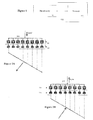
- Figure 2A illustrates one embodiment of a phased array 205 implemented for the directional transmission of sound.
- phased array 205 indudesvariable phase shifters 210 and micro speakers 220.
- each phase shifter 210 receives a signal to be transmitted and produces a tuning of a direction of phase propagation (e.g., the direct ion of the wave propagation is set by a wavefront), in which a wavefront is defined as points of equal phase in a moving wave.
- the control of phase by phase shifters 210 enables the control of directionality and beam shift.
- a variable configuration for each phase shifter 210 allows for a tunable steering angle.
- phase shifters 210 are digital components. However, analog components may be implemented.
- a micro speaker 220 is coupled to each phase shifter 210 to produce an audible sound in response to electrical audio signals received from a respective phase shifter 210.
- the result of the sound produced by the micro speakers 220 is a steered acoustic wavefront generated at phased array 205.
- micro speakers 220 are piezoelectric speakers at which an electromagnetic field produces a piezo response (e.g., vibration that produces sound).
- micro speakers 220 are implemented via other technologies (e.g., micro-magnetic or Microelectromechanical systems (MEMS)).
- the arrayed waveguide may comprise a reception component implemented to selectively eliminate noise sources from an ambient environment at a user location.
- Figure 2B illustrates one embodiment of a phased array 207 implemented for the directional reception of sound.
- micro speakers 220 are replaced with micro receivers (or micro phones) 230.
- micro receivers 230 may be smaller than micro speakers 220 since less power is necessary to receive, rather than transmit sound.
- micro receivers 230 are controlled by variable phase shifters 210 control directionality and beam shift, and enable a tunable starring angle. As discussed above with reference to micro speakers 220, micro receivers 230 may utilize piezoelectric, micro-magneticor MEMS components.
- phased arrays 120 may be integrated into a monitor or display device to form a two-dimensional array for three-dimensional angular control of acoustic signals.
- Figure 3 illustrates one embodiment of a display device 300 incorporating phased array 205 and 207.
- phased arrays 120 may also produce noise cancelled environments.
- Noise cancelled environments provide a superior voice interface with computers systems.
- integrated phase arrays 120 include transparent acoustic transmitters and transparent acoustic receivers.
- the ambient noise is sensed via a phased array 207 and an opposing phase cancellation sound is generated using the phase arrays 205 to create a noise cancelled environment.
- a digital algorithm is used to separate the local sounds from the remote noise sources.
- a noise cancelled environment permits the implementation of a crowded environment with multiple voice controlled computer devices.
- Figure 4 illustrates one embodiment of a crowded environment with multiple voice controlled computer systems. As shown in Figure 4 , the noise cancelled environment effectively provides a virtual acoustic insulated box for each user.
- phased arrays 120 may be integrated on to user clothing to enable directional transmission/reception of sound.
- Figure 5 illustrates one embodiment in which wearable acoustic phased arrays are integrated on a shirt to enable one to one communication. Such one to one communication may be implemented in a remote whispering system.
- a remote whispering system enables a personal directional sound communication method where a one to one communication can be established in a crowded room between two people or between one person and a computer system using a phase array for sound reception and transmission.
- Figure 6 illustrates one embodiment of a crowded room/office environment in which phase arrays 120 are used.
- the sending system/user aims the signal at the appropriate location.
- a visual or electronic honing system may be used to steer the sound to the proper location.
- the honing system is either manually controlled or uses a pointer operated by the user.
- Phase arrays 120 may also be used in multiple voice controlled electronics located in a home environment. Thus, a user may have direct personal sound communication with consumer electronic devices via phase arrays 120.
- Figure 7 illustrates one embodiment of such a home environment having voice controlled electronics with acoustic phased arrays 120.
- phased arrays 120 may be incorporated in other types of devices to provide for a directional transmission/reception of sound.
- phased arrays 120 may be included in small form factor mobile computers such as tablets, telephones, Global Positioning systems (GPSs), etc.
- GPSs Global Positioning systems
- the above-described mechanism allows for one to one sound communication in a crowded noisy environment between humans or human and a computer system.
- the mechanism also enables increased range and addressability of sound communications, large number of users to use voice interface to computers and electronics, as well as creates scalable noise controlled (via removal of ambient noise) environments.
- Figure 8 illustrates one embodiment of a computer system 800.
- the computer system 800 (also referred to as the electronic system 800) as depicted can embody acoustic system 100.
- the computer system 800 may be a mobile device such as a netbook computer.
- the computer system 800 may be a mobile device such as a wireless smart phone.
- the computer system 800 may be a desktop computer.
- the computer system 800 may be a hand-held reader.
- the computer system 800 may be a server system.
- the computer system 800 may be a supercomputer or high-performance computing system.
- the electronic system 800 is a computer system that indudesa system bus 820 to electrically couple the various components of the electronic system 800.
- the system bus 820 is a single bus or any combination of busses according to various embodiments.
- the electronic system 800 includes a voltage source 830 that provides power to the integrated circuit 810. In some embodiments, the voltage source 830 supplies current to the integrated circuit 810 through the system bus 820.
- the integrated circuit 810 is electrically coupled to the system bus 820 and includes any circuit, or combination of circuits according to an embodiment.
- the integrated circuit 810 indudesa processor 812 that can be of any type.
- the processor 812 may mean any type of circuit such as, but not limited to, a microprocessor, a microcontroller, a graphics processor, a digital signal processor, or another processor.
- the processor 812 includes a processor 110 as disclosed herein.
- SRAM embodiments are found in memory caches of the processor.
- Other types of circuits that can be included in the integrated circuit 810 are a custom circuit or an application-specific integrated circuit (ASIC), such as a communications circuit 814 for use in wireless devices such as cellular telephones, smart phones, pagers, portable computers, two-way radios, and similar electronic systems, or a communicationscircuit for servers.
- the integrated circuit 810 includes on-die memory 816 such as static random-access memory (SRAM).
- the integrated circuit 410 includes embedded on-die memory 816 such as embedded dynamic random-access memory (eDRAM).
- the integrated circuit 810 is complemented with a subsequent integrated circuit 811.
- Useful embodiments include a dual processor 813 and a dual communications circuit 815 and dual on-die memory 817 such as SRAM.
- the dual integrated circuit 810 includes embedded on-die memory 417 such as eDRAM.
- the electronic system 800 also includes an external memory 840 that in turn may include one or more memory elements suitable to the particular application, such as a main memory 842 in the form of RAM, one or more hard drives 844, and/or one or more drives that handle removable media 846, such as diskettes, compact disks (CDs), digital variable disks (DVDs), flash memory drives, and other removable media known in the art.
- the external memory 840 may also be embedded memory 848 such as the first die in an embedded TSV die stack, according to an embodiment.
- the electronic system 800 also includes a display device 850, an audio output 860.
- the electronic system 800 includes an input device such as a controller 870 that may be a keyboard, mouse, trackball, game controller, microphone, voice-recognition device, or any other input devicethat inputs information into the electronic system 800.
- an input device 870 is a camera.
- an input device 870 is a digital sound recorder.
- an input device 870 is a camera and a digital sound recorder.
- the integrated circuit 810 can be implemented in a number of different embodiments, including an acoustic system.
- the elements, materials, geometries, dimensions, and sequence of operations can all be varied to suit particular I/O coupling requirements including array contact count, array contact configuration for a microelectronic die embedded in a processor mounting substrate according to any of the several disclosed semiconductor die packaged with a thermal interface unit and their equivalents.
- a foundation substrate may be included, as represented by the dashed line of Figure 8 .
- Passive devices may also be included, as is also depicted in Figure 8 .
Landscapes
- Health & Medical Sciences (AREA)
- Otolaryngology (AREA)
- Physics & Mathematics (AREA)
- Engineering & Computer Science (AREA)
- Acoustics & Sound (AREA)
- Signal Processing (AREA)
- Multimedia (AREA)
- Circuit For Audible Band Transducer (AREA)
- Soundproofing, Sound Blocking, And Sound Damping (AREA)
- Variable-Direction Aerials And Aerial Arrays (AREA)
- Obtaining Desirable Characteristics In Audible-Bandwidth Transducers (AREA)
- Measurement Of Velocity Or Position Using Acoustic Or Ultrasonic Waves (AREA)
- Transducers For Ultrasonic Waves (AREA)
Abstract
Description
- The present disclosure generally relates to a mechanism for implementing remote sound communication.
- Current methods and systems that compensate for noise interference are a passive means of reducing the interfering noise surrounding. For example, voice interfaces are typically not available in crowded environments because computer voice recognition is not operable in a noisy, crowded environment. Additionally, one to one personal directional sound communication mechanisms do not exist without the use of a telephone connection.
-
- [0003]
Figure 1 illustratesone embodiment of an acoustic system. - [0004]
Figures 2A and 2B illustrate embodiments of a phased array. - [0005]
Figure 3 illustrates one embodiment of a display device. - [0006]
Figure 4 illustrates one embodiment of a crowded environment with multiple voice controlled computer systems. - [0007]
Figure 5 illustrates one embodiment of a wearable acoustic phased array. - [0008]
Figure 6 illustrates one embodiment of a crowded room/office environment. - [0009]
Figure 7 illustrates one embodiment of voice controlled electronics with acoustic phased arrays. - [0010]
Figure 8 illustrates one embodiment of a computer system. - In the following description, numerous specific details are set forth in order to provide a thorough understanding of various embodiments. However, various embodiments of the invention may be practiced without the specific details. In other instances, well-known methods, procedures, components, and circuits have not been described in detail so as not to obscure the particular embodiments of the invention.
- Reference in the specification to "one embodiment" or "an embodiment" meansthat a particular feature, structure, or characteristic described in connection with the embodiment may be included in at least an implementation. The appearances of the phrase " in one embodiment" in various places in the specification may or may not be all referring to the same embodiment.
-
Figure 1 illustrates one embodiment of anacoustic system 100.System 100 includes aphased array 120 andprocessor 110. According to one embodiment,processor 110 is an application processor (e.g., system on a chip (SoC)) designed to support applications running in an operating system environment. Thus,processor 110 provides a self-contained operating environment that delivers all system capabilities needed to support an acoustic application, as well as those for other computing applications (e.g., including memory management, graphics processing and multimedia decoding). In other embodiments,processor 110 may be implemented by an application specific integrated circuit (ASIC). - According to one embodiment,
phased array 120 includes an arrayed waveguide for acousticwavesthat enables directional and enhanced range sound communication. Thus,phased array 120 includes a transmission component that performs a directional transmission of sound.Figure 2A illustrates one embodiment of aphased array 205 implemented for the directional transmission of sound. - Referring to
Figure 2A , phasedarray 205indudesvariable phase shifters 210 andmicro speakers 220. In one embodiment, eachphase shifter 210 receives a signal to be transmitted and produces a tuning of a direction of phase propagation (e.g., the direct ion of the wave propagation is set by a wavefront), in which a wavefront is defined as points of equal phase in a moving wave. The control of phase byphase shifters 210 enables the control of directionality and beam shift. Moreover, a variable configuration for eachphase shifter 210 allows for a tunable steering angle. In one embodiment,phase shifters 210 are digital components. However, analog components may be implemented. - A
micro speaker 220 is coupled to eachphase shifter 210 to produce an audible sound in response to electrical audio signals received from arespective phase shifter 210. The result of the sound produced by themicro speakers 220 is a steered acoustic wavefront generated atphased array 205. In one embodiment,micro speakers 220 are piezoelectric speakers at which an electromagnetic field produces a piezo response (e.g., vibration that produces sound). In another embodiment,micro speakers 220 are implemented via other technologies (e.g., micro-magnetic or Microelectromechanical systems (MEMS)). - In a further embodiment, the arrayed waveguide may comprise a reception component implemented to selectively eliminate noise sources from an ambient environment at a user location.
Figure 2B illustrates one embodiment of aphased array 207 implemented for the directional reception of sound. In such an embodiment,micro speakers 220 are replaced with micro receivers (or micro phones) 230. In a further embodiment,micro receivers 230 may be smaller thanmicro speakers 220 since less power is necessary to receive, rather than transmit sound. - In a direction reception embodiment,
micro receivers 230 are controlled byvariable phase shifters 210 control directionality and beam shift, and enable a tunable starring angle. As discussed above with reference tomicro speakers 220,micro receivers 230 may utilize piezoelectric, micro-magneticor MEMS components. - According to one embodiment, phased arrays 120 (e.g., 205 and/or 207) may be integrated into a monitor or display device to form a two-dimensional array for three-dimensional angular control of acoustic signals.
Figure 3 illustrates one embodiment of adisplay device 300 incorporatingphased array - Integration of
phased arrays 120 into electronic displays may also produce noise cancelled environments. Noise cancelled environments provide a superior voice interface with computers systems. In such an embodiment, integratedphase arrays 120 include transparent acoustic transmitters and transparent acoustic receivers. The ambient noise is sensed via aphased array 207 and an opposing phase cancellation sound is generated using thephase arrays 205 to create a noise cancelled environment. In a further embodiment, a digital algorithm is used to separate the local sounds from the remote noise sources. - In one embodiment, a noise cancelled environment permits the implementation of a crowded environment with multiple voice controlled computer devices.
Figure 4 illustrates one embodiment of a crowded environment with multiple voice controlled computer systems. As shown inFigure 4 , the noise cancelled environment effectively provides a virtual acoustic insulated box for each user. - In another embodiment,
phased arrays 120 may be integrated on to user clothing to enable directional transmission/reception of sound.Figure 5 illustrates one embodiment in which wearable acoustic phased arrays are integrated on a shirt to enable one to one communication. Such one to one communication may be implemented in a remote whispering system. - In one embodiment, a remote whispering system enables a personal directional sound communication method where a one to one communication can be established in a crowded room between two people or between one person and a computer system using a phase array for sound reception and transmission.
Figure 6 illustrates one embodiment of a crowded room/office environment in whichphase arrays 120 are used. In such an embodiment, the sending system/user aims the signal at the appropriate location. Further, a visual or electronic honing system may be used to steer the sound to the proper location. In this embodiment, the honing system is either manually controlled or uses a pointer operated by the user. -
Phase arrays 120 may also be used in multiple voice controlled electronics located in a home environment. Thus, a user may have direct personal sound communication with consumer electronic devices viaphase arrays 120.Figure 7 illustrates one embodiment of such a home environment having voice controlled electronics with acoustic phasedarrays 120. - Although not described specifically herein, phased
arrays 120 may be incorporated in other types of devices to provide for a directional transmission/reception of sound. For instance, phasedarrays 120 may be included in small form factor mobile computers such as tablets, telephones, Global Positioning systems (GPSs), etc. - The above-described mechanism allows for one to one sound communication in a crowded noisy environment between humans or human and a computer system. The mechanism also enables increased range and addressability of sound communications, large number of users to use voice interface to computers and electronics, as well as creates scalable noise controlled (via removal of ambient noise) environments.
-
Figure 8 illustrates one embodiment of acomputer system 800. The computer system 800 (also referred to as the electronic system 800) as depicted can embodyacoustic system 100. Thecomputer system 800 may be a mobile device such as a netbook computer. Thecomputer system 800 may be a mobile device such as a wireless smart phone. Thecomputer system 800 may be a desktop computer. Thecomputer system 800 may be a hand-held reader. Thecomputer system 800 may be a server system. Thecomputer system 800 may be a supercomputer or high-performance computing system. - In an embodiment, the
electronic system 800 is a computer system that indudesasystem bus 820 to electrically couple the various components of theelectronic system 800. Thesystem bus 820 is a single bus or any combination of busses according to various embodiments. Theelectronic system 800 includes avoltage source 830 that provides power to theintegrated circuit 810. In some embodiments, thevoltage source 830 supplies current to theintegrated circuit 810 through thesystem bus 820. - The
integrated circuit 810 is electrically coupled to thesystem bus 820 and includes any circuit, or combination of circuits according to an embodiment. In an embodiment, theintegrated circuit 810indudesa processor 812 that can be of any type. As used herein, theprocessor 812 may mean any type of circuit such as, but not limited to, a microprocessor, a microcontroller, a graphics processor, a digital signal processor, or another processor. In an embodiment, theprocessor 812 includes aprocessor 110 as disclosed herein. - In an embodiment, SRAM embodiments are found in memory caches of the processor. Other types of circuits that can be included in the
integrated circuit 810 are a custom circuit or an application-specific integrated circuit (ASIC), such as acommunications circuit 814 for use in wireless devices such as cellular telephones, smart phones, pagers, portable computers, two-way radios, and similar electronic systems, or a communicationscircuit for servers. In an embodiment, theintegrated circuit 810 includes on-die memory 816 such as static random-access memory (SRAM). In an embodiment, the integrated circuit 410 includes embedded on-die memory 816 such as embedded dynamic random-access memory (eDRAM). - In an embodiment, the
integrated circuit 810 is complemented with a subsequentintegrated circuit 811. Useful embodiments include adual processor 813 and adual communications circuit 815 and dual on-die memory 817 such as SRAM. In an embodiment, the dualintegrated circuit 810 includes embedded on-die memory 417 such as eDRAM. - In an embodiment, the
electronic system 800 also includes anexternal memory 840 that in turn may include one or more memory elements suitable to the particular application, such as amain memory 842 in the form of RAM, one or morehard drives 844, and/or one or more drives that handleremovable media 846, such as diskettes, compact disks (CDs), digital variable disks (DVDs), flash memory drives, and other removable media known in the art. Theexternal memory 840 may also be embeddedmemory 848 such as the first die in an embedded TSV die stack, according to an embodiment. - In an embodiment, the
electronic system 800 also includes adisplay device 850, anaudio output 860. In an embodiment, theelectronic system 800 includes an input device such as acontroller 870 that may be a keyboard, mouse, trackball, game controller, microphone, voice-recognition device, or any other input devicethat inputs information into theelectronic system 800. In an embodiment, aninput device 870 is a camera. In an embodiment, aninput device 870 is a digital sound recorder. In an embodiment, aninput device 870 is a camera and a digital sound recorder. - Asshown herein, the
integrated circuit 810 can be implemented in a number of different embodiments, including an acoustic system. The elements, materials, geometries, dimensions, and sequence of operations can all be varied to suit particular I/O coupling requirements including array contact count, array contact configuration for a microelectronic die embedded in a processor mounting substrate according to any of the several disclosed semiconductor die packaged with a thermal interface unit and their equivalents. A foundation substrate may be included, as represented by the dashed line ofFigure 8 . Passive devices may also be included, as is also depicted inFigure 8 . - Although embodiments of the invention have been described in language specific to structural features and/or methodological acts, it is to be understood that claimed subject matter may not be limited to the specific features or actsdescribed. Rather, the specific features and acts are disclosed as sample forms of implementing the claimed subject matter.
Claims (15)
- A phased array comprising one or more phase shifters to produce an arrayed waveguide for acousticwavesto enable directional sound communication.
- The phased array of daim 1, wherein the phase shifters have a variable configuration to enable a tunable steering angle.
- The phased array of claims 1 or 2, wherein the phased array comprises a transmission component to perform a directional transmission of sound.
- The phased array of claim 3, wherein the transmission component comprises a micro speaker coupled to each of the one or more phase shifters, preferably wherein each phase shifter receives a signal to be transmitted and produces a tuning of a direction of phase propagation.
- The phased array of daim 3, wherein the phased array comprises a reception component to perform a directional reception of sound.
- The phased array of claim 5 wherein the reception component comprises a micro receiver coupled to each of the one or more phase shifters.
- The phased array of claim 5 or 6, wherein each phase shifter receives a signal from a respective micro receiver, or wherein the phase shifters are implemented using one of digital, analog or mixed-signal electronics.
- The phased array of daim 4, wherein the micro speakers are comprised of one of micromechanical or a micromagnetic technologies and/or wherein each micro speaker produces sound in response to electrical audio signals received from a respective phase shifter, preferably wherein the audible sound produced by the micro speakers is a steered acoust ic wavefront.
- A method comprising:receiving a signal to at one or more phase shifters; andgenerating an arrayed waveguide for acoustic waves in order to enable directional sound communication.
- The method of daim 9, wherein the phase shifters have a variable configuration to enable a tunable steering angle in two or three dimensions.
- The method of daim 10, wherein the one or more phase shifters receive a signal to be transmitted prior to producing the arrayed waveguide, preferably further comprising transmitting a signal from each phase shifter to a micro speaker to produce a steered acoust ic wavefront.
- The method of claim 10, wherein the one or more phase shifters receive a signal from a micro receiver.
- A system comprising:a processor; anda phased array according to any one of claims 1 to 8, coupled to the processor, having an arrayed component for acoustic signals to enable directional sound communication.
- The system of daim 13, wherein transmission and reception component phase arrays are integrated into a display device to form a two-dimensional array for three-dimensional angular control of acoustic signals, preferably wherein integration of transmission and reception component phase arrays into a display device produces a noise cancelled environment.
- The system of daim 13, wherein transmission and reception component phase arrays are integrated into clothing to enable directional transmission/reception of sound, or wherein the directional transmission/reception of sound enables establishing one to one communication in a crowded room.
Applications Claiming Priority (1)
| Application Number | Priority Date | Filing Date | Title |
|---|---|---|---|
| US13/725,773 US9183829B2 (en) | 2012-12-21 | 2012-12-21 | Integrated accoustic phase array |
Publications (2)
| Publication Number | Publication Date |
|---|---|
| EP2747076A2 true EP2747076A2 (en) | 2014-06-25 |
| EP2747076A3 EP2747076A3 (en) | 2017-12-13 |
Family
ID=49765316
Family Applications (1)
| Application Number | Title | Priority Date | Filing Date |
|---|---|---|---|
| EP13195690.6A Withdrawn EP2747076A3 (en) | 2012-12-21 | 2013-12-04 | Integrated accoustic phase array |
Country Status (8)
| Country | Link |
|---|---|
| US (2) | US9183829B2 (en) |
| EP (1) | EP2747076A3 (en) |
| JP (1) | JP5746314B2 (en) |
| KR (2) | KR101589517B1 (en) |
| CN (1) | CN103888872B (en) |
| BR (1) | BR102013032020A8 (en) |
| SG (1) | SG2013093513A (en) |
| TW (2) | TWI603323B (en) |
Families Citing this family (4)
| Publication number | Priority date | Publication date | Assignee | Title |
|---|---|---|---|---|
| US9183829B2 (en) * | 2012-12-21 | 2015-11-10 | Intel Corporation | Integrated accoustic phase array |
| CN106899356A (en) * | 2017-04-06 | 2017-06-27 | 宇龙计算机通信科技(深圳)有限公司 | A kind of communication means and communicator transaudient based on orientation |
| US11973257B2 (en) | 2020-09-25 | 2024-04-30 | GlaiveRF, Inc. | Wearable accessory with phased array antenna system |
| US12066860B2 (en) | 2020-11-13 | 2024-08-20 | GlaiveRF, Inc. | Wearable accessory with phased array antenna system |
Family Cites Families (21)
| Publication number | Priority date | Publication date | Assignee | Title |
|---|---|---|---|---|
| US3821740A (en) * | 1972-07-03 | 1974-06-28 | Raytheon Co | Super directive system |
| US4333028A (en) * | 1980-04-21 | 1982-06-01 | Milltronics Ltd. | Damped acoustic transducers with piezoelectric drivers |
| US6239348B1 (en) * | 1999-09-10 | 2001-05-29 | Randall B. Metcalf | Sound system and method for creating a sound event based on a modeled sound field |
| US6829131B1 (en) | 1999-09-13 | 2004-12-07 | Carnegie Mellon University | MEMS digital-to-acoustic transducer with error cancellation |
| WO2001023104A2 (en) * | 1999-09-29 | 2001-04-05 | 1...Limited | Method and apparatus to direct sound using an array of output transducers |
| WO2002013162A1 (en) * | 2000-08-04 | 2002-02-14 | Schrage Martin H | Audible communication system |
| US20050147261A1 (en) | 2003-12-30 | 2005-07-07 | Chiang Yeh | Head relational transfer function virtualizer |
| JP2006109340A (en) | 2004-10-08 | 2006-04-20 | Yamaha Corp | Acoustic system |
| DE102004057500B3 (en) * | 2004-11-29 | 2006-06-14 | Fraunhofer-Gesellschaft zur Förderung der angewandten Forschung e.V. | Device and method for controlling a sound system and public address system |
| ES2388392T3 (en) * | 2006-05-22 | 2012-10-15 | Audio Pixels Ltd. | Direct digital speaker device that has a desired directivity pattern |
| KR100919642B1 (en) * | 2007-12-17 | 2009-09-30 | 한국전자통신연구원 | Directive Speaker and mobile station thereof |
| JP5315865B2 (en) * | 2008-09-02 | 2013-10-16 | ヤマハ株式会社 | Sound field transmission system and sound field transmission method |
| JP2010124370A (en) * | 2008-11-21 | 2010-06-03 | Fujitsu Ltd | Signal processing device, signal processing method, and signal processing program |
| CN101588524A (en) * | 2009-07-08 | 2009-11-25 | 电子科技大学 | Directionally adjustable miniature audio frequency directional loudspeaker |
| US20110058676A1 (en) * | 2009-09-07 | 2011-03-10 | Qualcomm Incorporated | Systems, methods, apparatus, and computer-readable media for dereverberation of multichannel signal |
| JP5060589B2 (en) * | 2010-06-01 | 2012-10-31 | 日本電信電話株式会社 | Sound collecting / reproducing apparatus, method and program, and hands-free apparatus |
| US8638951B2 (en) * | 2010-07-15 | 2014-01-28 | Motorola Mobility Llc | Electronic apparatus for generating modified wideband audio signals based on two or more wideband microphone signals |
| JP2012029094A (en) * | 2010-07-23 | 2012-02-09 | Nec Casio Mobile Communications Ltd | Mobile terminal device |
| US8525868B2 (en) * | 2011-01-13 | 2013-09-03 | Qualcomm Incorporated | Variable beamforming with a mobile platform |
| US8737674B2 (en) * | 2011-02-11 | 2014-05-27 | Infineon Technologies Ag | Housed loudspeaker array |
| US9183829B2 (en) * | 2012-12-21 | 2015-11-10 | Intel Corporation | Integrated accoustic phase array |
-
2012
- 2012-12-21 US US13/725,773 patent/US9183829B2/en not_active Expired - Fee Related
-
2013
- 2013-11-26 TW TW105112607A patent/TWI603323B/en not_active IP Right Cessation
- 2013-11-26 TW TW102143016A patent/TWI540571B/en not_active IP Right Cessation
- 2013-12-04 EP EP13195690.6A patent/EP2747076A3/en not_active Withdrawn
- 2013-12-12 BR BR102013032020A patent/BR102013032020A8/en not_active Application Discontinuation
- 2013-12-17 SG SG2013093513A patent/SG2013093513A/en unknown
- 2013-12-19 KR KR1020130159490A patent/KR101589517B1/en active Active
- 2013-12-20 CN CN201310757192.6A patent/CN103888872B/en not_active Expired - Fee Related
- 2013-12-20 JP JP2013264606A patent/JP5746314B2/en active Active
-
2015
- 2015-05-29 KR KR1020150076246A patent/KR102037557B1/en active Active
- 2015-10-07 US US14/877,602 patent/US10074357B2/en active Active
Non-Patent Citations (1)
| Title |
|---|
| None |
Also Published As
| Publication number | Publication date |
|---|---|
| TW201428735A (en) | 2014-07-16 |
| CN103888872B (en) | 2017-10-27 |
| TWI603323B (en) | 2017-10-21 |
| US9183829B2 (en) | 2015-11-10 |
| KR102037557B1 (en) | 2019-10-28 |
| KR20150064007A (en) | 2015-06-10 |
| US10074357B2 (en) | 2018-09-11 |
| BR102013032020A8 (en) | 2018-05-29 |
| BR102013032020A2 (en) | 2015-11-24 |
| TW201642251A (en) | 2016-12-01 |
| SG2013093513A (en) | 2014-07-30 |
| JP5746314B2 (en) | 2015-07-08 |
| US20140176367A1 (en) | 2014-06-26 |
| EP2747076A3 (en) | 2017-12-13 |
| JP2014123952A (en) | 2014-07-03 |
| KR101589517B1 (en) | 2016-01-28 |
| KR20140081712A (en) | 2014-07-01 |
| TWI540571B (en) | 2016-07-01 |
| US20160027429A1 (en) | 2016-01-28 |
| CN103888872A (en) | 2014-06-25 |
Similar Documents
| Publication | Publication Date | Title |
|---|---|---|
| KR101955108B1 (en) | Valve for acoustic port | |
| JP4799443B2 (en) | Sound receiving device and method | |
| US10074357B2 (en) | Integrated acoustic phase array | |
| US7936894B2 (en) | Multielement microphone | |
| JP2009005071A (en) | Voice input/output device and speech apparatus | |
| US20230112073A1 (en) | Electronic device for controlling ambient sound based on audio scene and operating method thereof | |
| US20190058955A1 (en) | An acoustic apparatus and associated methods | |
| US8334732B2 (en) | Method and system for generating quadrature signals utilizing an on-chip transformer | |
| CN107465786B (en) | A kind of mobile terminal | |
| CN114125624B (en) | Active noise reduction method, noise reduction earphone and computer readable storage medium | |
| US11722814B2 (en) | Sound output apparatus | |
| KR102848942B1 (en) | Method for processing audio data and electronic device supporting the same | |
| CN119343909A (en) | Electronic device including a multi-channel grip sensor and method for sensing capacitance changes using the multi-channel grip sensor | |
| EP4344248A1 (en) | Electronic device comprising multi-way speaker, and electronic device operation method | |
| EP4589588A1 (en) | Electronic device, method, and non-transitory computer-readable recording medium for acoustic beamforming | |
| CN118489258A (en) | Wearable device | |
| KR20260004968A (en) | Wearable electronic device including antenna | |
| KR20250020251A (en) | Wearable electronic device comprising a speaker | |
| CN120036012A (en) | Electronic device and method for generating vibration sound signal | |
| KR20240026815A (en) | A headphone device capable of combining with wireless earphones and operation method of thereof and an wireless earphones | |
| KR20250085561A (en) | Electronic device, method, and non-transitory computer readable storage medium for acoustic beamforming | |
| JPH0230240B2 (en) | ZATSUONYOKUATSUHOHO |
Legal Events
| Date | Code | Title | Description |
|---|---|---|---|
| PUAI | Public reference made under article 153(3) epc to a published international application that has entered the european phase |
Free format text: ORIGINAL CODE: 0009012 |
|
| 17P | Request for examination filed |
Effective date: 20131204 |
|
| AK | Designated contracting states |
Kind code of ref document: A2 Designated state(s): AL AT BE BG CH CY CZ DE DK EE ES FI FR GB GR HR HU IE IS IT LI LT LU LV MC MK MT NL NO PL PT RO RS SE SI SK SM TR |
|
| AX | Request for extension of the european patent |
Extension state: BA ME |
|
| PUAL | Search report despatched |
Free format text: ORIGINAL CODE: 0009013 |
|
| AK | Designated contracting states |
Kind code of ref document: A3 Designated state(s): AL AT BE BG CH CY CZ DE DK EE ES FI FR GB GR HR HU IE IS IT LI LT LU LV MC MK MT NL NO PL PT RO RS SE SI SK SM TR |
|
| AX | Request for extension of the european patent |
Extension state: BA ME |
|
| RIC1 | Information provided on ipc code assigned before grant |
Ipc: H04R 1/32 20060101ALI20171108BHEP Ipc: G10K 11/34 20060101AFI20171108BHEP |
|
| RBV | Designated contracting states (corrected) |
Designated state(s): AL AT BE BG CH CY CZ DE DK EE ES FI FR GB GR HR HU IE IS IT LI LT LU LV MC MK MT NL NO PL PT RO RS SE SI SK SM TR |
|
| STAA | Information on the status of an ep patent application or granted ep patent |
Free format text: STATUS: THE APPLICATION HAS BEEN WITHDRAWN |
|
| 18W | Application withdrawn |
Effective date: 20191106 |