EP2746849A1 - Projection apparatus comprising parallel circuit boards - Google Patents
Projection apparatus comprising parallel circuit boards Download PDFInfo
- Publication number
- EP2746849A1 EP2746849A1 EP13187354.9A EP13187354A EP2746849A1 EP 2746849 A1 EP2746849 A1 EP 2746849A1 EP 13187354 A EP13187354 A EP 13187354A EP 2746849 A1 EP2746849 A1 EP 2746849A1
- Authority
- EP
- European Patent Office
- Prior art keywords
- circuit board
- projection apparatus
- power
- casing
- host circuit
- Prior art date
- Legal status (The legal status is an assumption and is not a legal conclusion. Google has not performed a legal analysis and makes no representation as to the accuracy of the status listed.)
- Granted
Links
- 230000003287 optical effect Effects 0.000 claims abstract description 7
- 238000011144 upstream manufacturing Methods 0.000 claims description 2
- 230000008901 benefit Effects 0.000 description 6
- 230000002159 abnormal effect Effects 0.000 description 3
- 238000010586 diagram Methods 0.000 description 2
- 238000012986 modification Methods 0.000 description 2
- 230000004048 modification Effects 0.000 description 2
- 230000008878 coupling Effects 0.000 description 1
- 238000010168 coupling process Methods 0.000 description 1
- 238000005859 coupling reaction Methods 0.000 description 1
- 230000000694 effects Effects 0.000 description 1
- 238000005516 engineering process Methods 0.000 description 1
- 238000003384 imaging method Methods 0.000 description 1
- 238000004519 manufacturing process Methods 0.000 description 1
Images


Classifications
-
- G—PHYSICS
- G03—PHOTOGRAPHY; CINEMATOGRAPHY; ANALOGOUS TECHNIQUES USING WAVES OTHER THAN OPTICAL WAVES; ELECTROGRAPHY; HOLOGRAPHY
- G03B—APPARATUS OR ARRANGEMENTS FOR TAKING PHOTOGRAPHS OR FOR PROJECTING OR VIEWING THEM; APPARATUS OR ARRANGEMENTS EMPLOYING ANALOGOUS TECHNIQUES USING WAVES OTHER THAN OPTICAL WAVES; ACCESSORIES THEREFOR
- G03B21/00—Projectors or projection-type viewers; Accessories therefor
- G03B21/14—Details
- G03B21/145—Housing details, e.g. position adjustments thereof
-
- G—PHYSICS
- G03—PHOTOGRAPHY; CINEMATOGRAPHY; ANALOGOUS TECHNIQUES USING WAVES OTHER THAN OPTICAL WAVES; ELECTROGRAPHY; HOLOGRAPHY
- G03B—APPARATUS OR ARRANGEMENTS FOR TAKING PHOTOGRAPHS OR FOR PROJECTING OR VIEWING THEM; APPARATUS OR ARRANGEMENTS EMPLOYING ANALOGOUS TECHNIQUES USING WAVES OTHER THAN OPTICAL WAVES; ACCESSORIES THEREFOR
- G03B21/00—Projectors or projection-type viewers; Accessories therefor
- G03B21/14—Details
- G03B21/16—Cooling; Preventing overheating
-
- G—PHYSICS
- G03—PHOTOGRAPHY; CINEMATOGRAPHY; ANALOGOUS TECHNIQUES USING WAVES OTHER THAN OPTICAL WAVES; ELECTROGRAPHY; HOLOGRAPHY
- G03B—APPARATUS OR ARRANGEMENTS FOR TAKING PHOTOGRAPHS OR FOR PROJECTING OR VIEWING THEM; APPARATUS OR ARRANGEMENTS EMPLOYING ANALOGOUS TECHNIQUES USING WAVES OTHER THAN OPTICAL WAVES; ACCESSORIES THEREFOR
- G03B21/00—Projectors or projection-type viewers; Accessories therefor
- G03B21/14—Details
- G03B21/20—Lamp housings
- G03B21/206—Control of light source other than position or intensity
-
- H—ELECTRICITY
- H04—ELECTRIC COMMUNICATION TECHNIQUE
- H04N—PICTORIAL COMMUNICATION, e.g. TELEVISION
- H04N9/00—Details of colour television systems
- H04N9/12—Picture reproducers
- H04N9/31—Projection devices for colour picture display, e.g. using electronic spatial light modulators [ESLM]
- H04N9/3141—Constructional details thereof
- H04N9/3144—Cooling systems
Definitions
- the invention relates to an optical apparatus. More particularly, the invention relates to a projection apparatus.
- a projection apparatus is an apparatus used to produce an image with large size.
- the imaging mechanism of the projection apparatus is that an illuminating beam generated by a light source is transformed into an image beam by a light valve and then the image beam is further transformed into a projecting beam by a projection lens, so as to project the projecting beam onto a screen or a wall to form an image. Due to the development of projecting technology and reducing the fabrication cost, the application of projection apparatus has extended from the use in business to the use in home.
- the appearance of the conventional projection apparatus usually is a flat shape, so the circuit boards inside the conventional projection apparatus are usually divided into two circuit boards.
- One circuit board includes a digital micromirror device (DMD) chip and a control module of the DMD chip.
- Another circuit board includes the central processing unit (CPU) of the projection apparatus.
- the signals between the two circuit boards are transmitted by an one-to-one connector or a flat cable.
- the above assembling manner may cause an abnormal image or an abnormal operation of the host, due to the factors of poor quality for the connector or the flat cable, poor assembly tolerance, and improper assembly.
- U.S. Patents No. 6155687 , 7301691 , and 7883215 have disclosed an projection apparatus, of which the DMD chip is directly implemented on the motherboard to reduce abnormal effect due to the above factors of poor quality for the connector or the flat cable, poor assembly tolerance, and improper assembly.
- the electrical connector of the projection apparatus for communicating with an external device is usually implemented on the edge region of the motherboard and the port of the connector is exposed to an opening of the apparatus casing.
- the projection apparatus can receive the electronic signals from outside, such as the video signals, to correspondingly produce the image.
- the location of the connector on the motherboard has to be adjusted as well. This would cause re-design for the motherboard. The cost would increase.
- the U.S. Patent Publication 2010/0073581 also discloses a projector, which uses an expansion module by external attachment to receive the video signal.
- the invention provides a projection apparatus, which has less volume.
- an embodiment of the invention provides a projection apparatus, including a casing, a motherboard, a power board, a light source, and a projection lens.
- the motherboard includes a host circuit board, a light valve, and a CPU.
- the host circuit board is contained inside the casing.
- the light valve is implemented on the host circuit board.
- the CPU is implemented on the host circuit board.
- the power board includes a power circuit board and an AC/DC power module.
- the power circuit board is contained inside the casing.
- the AC/DC power module is implemented on the power circuit board.
- the light source is contained inside the casing and used to produce an illuminating beam.
- the light valve is used to transform the illuminating beam into an image beam.
- the projection lens is contained inside the casing and used to transform the image beam into a projecting beam.
- the power circuit board is parallel to the host circuit board. An optical axis of the projection lens is perpendicular to the host circuit board and the power circuit board.
- the embodiment of the invention could have at least one following advantage.
- the power circuit board is parallel to the host circuit board and the optical axis of the projection lens is perpendicular to the host circuit board and the power circuit board. This assembly could reduce the volume of the projection apparatus.
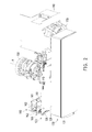
- FIG. 1 is a perspective view illustrating a projection apparatus according to an embodiment of the invention.
- FIG. 2 is a perspective view illustrating parts of the projection apparatus in FIG. 1 .
- FIG. 3 is a block diagram illustrating the projection apparatus in FIG. 1 .
- FIG. 4A is a perspective view illustrating the motherboard and the expansion board of the projection apparatus in FIG. 1 .
- FIG. 4B is an exploded view illustrating the motherboard and the expansion board in FIG. 4A .
- FIG. 5 is a drawing schematically illustrating a top view of the projection apparatus in FIG. 1 .
- FIG. 1 is a perspective view illustrating a projection apparatus according to an embodiment of the invention.
- FIG. 2 is a perspective view illustrating parts of the projection apparatus in FIG. 1 .
- the projection apparatus 100 of the embodiment includes a casing 110, a motherboard 120, and a power board 130.
- the motherboard 120 and the power board 130 are implemented inside the casing 110.
- FIG. 3 is a block diagram illustrating the projection apparatus in FIG. 1 .
- the motherboard 120 includes a host circuit board 121 and a light valve 122.
- the host circuit board 121 is contained inside the casing 110 as shown in FIG. 1 .
- the light valve 122 is implemented on the host circuit board 121.
- the power board 130 includes a power circuit board 131, and the power circuit board 131 is contained inside the casing 110.
- the projection apparatus 100 further includes a light source 140 and a projection lens 150.
- the light source 140 is contained inside the casing 110 and used to provide an illuminating beam L1.
- the light valve 122 is used to transform the illuminating beam L1 into an image beam L2.
- the projection lens 150 is contained inside the casing 110 and used to transform the image beam L2 into a projecting beam L3.
- the power circuit board 131 is parallel to the host circuit board 121, and an optical axis A of the projection lens 150, as shown in FIG. 2 , is perpendicular to the host circuit board 121 and the power circuit board 131.
- the volume of the projection apparatus 100 could be reduced.
- the motherboard 120 further includes a central processing unit (CPU) 123, and the CPU 123 is implemented on the host circuit board 121.
- the CPU 123 is electrically coupled to the light valve 122 through the host circuit board 121 to control the light valve 122.
- the motherboard 120 further includes a light valve control module 124.
- the light valve control module 124 is electrically connected to the light valve 122 and the CPU 123 through the host circuit board 121, to receive the instruction from the CPU 123 and then control the light valve 122.
- the power board 130 further includes an AC (alternating current) / DC (direct current) power module 132.
- the AC/DC power module 132 is implemented on the power circuit board 131.
- the power board 130 further includes a light source driving module 133.
- the light source driving module 133 is implemented on the power circuit board 131 and electrically connected to the light source 140 and the CPU 123 to receive the instruction from the CPU 123 and then to drive the light source 140.
- the motherboard 120 could further include a DC power converting module 125.
- the DC power converting module 125 is implemented on the host circuit board 121, to receive the direct current provided from the AC/DC power module 132.
- FIG. 4A is a perspective view illustrating the motherboard and the expansion board of the projection apparatus in FIG. 1 .
- FIG. 4B is an exploded view illustrating the motherboard and the expansion board in FIG. 4A .
- the projection apparatus 100 could include one or more expansion boards 160, which could be implemented on the host circuit board 121 by stacking with overlapping, as shown in FIG. 2 .
- each expansion board 160 includes an expansion circuit board 161 and one or more expansion components 162.
- the expansion circuit board 161 is contained inside the casing 110, as shown in FIG. 1 , and electrically connected to the host circuit board 121.
- the expansion components 162 are implemented on the expansion circuit board 161.
- the expansion circuit board 161 is parallel to the host circuit board 121, and could be located at the same side as the location of the projection lens 150 on the host circuit board 121, but the invention is not limited to this configuration.
- the expansion components 162 could be treated as video connector, such as S-video connector, RCA connector and RS232 connector, and so on.
- expansion components 162 could transmit the signals to the CPU 123, wherein the signals have been processed by corresponding circuit modules, such as video decoder, RS232 receiving module, and so on.
- One or more expansion boards 160 are implemented on the host circuit board 121 by stacking with overlapping, so the inner space of the projection apparatus 100 could be more efficiently used, and volume of the projection apparatus 100 could be reduced.
- the motherboard 120 could further include one or more electrical connectors 126, such as HDMI connector, VGA connector, and USB connector, and so on. These electrical connectors 126 have been implemented on the host circuit board 121 and could transmit the signals to the CPU 123, in which the signals have been processed by the corresponding circuit module, such as signal receiving module of digital image and analog-to-digital image converter and so on.
- the invention is not limited to this manner, the foregoing electrical connectors 126 could also be treated as the expansion components 162 and implemented on the expansion circuit board 161.
- FIG. 5 is a drawing schematically illustrating a top view of the projection apparatus in FIG. 1 .
- the projection apparatus 100 could further include a fan 170.
- the fan 170 is contained inside the casing 110 and used to generate active air circulation.
- the active air circulation flows through the space between the host circuit board 121 and the power circuit board 131.
- the space between the host circuit board 121 and the power circuit board 131 is located at the upstream of the active air circulation generated by the fan 170.
- the light source 140 is located at the downstream of the active air circulation generated by the fan 170.
- the power circuit board is parallel to the host circuit board, and the optical axis of the projection lens is perpendicular to the host circuit board and the power circuit board.
- This structure allows the volume of the projection apparatus to be reduced.
- the space between the host circuit board and the power circuit board could become as a channel for air circulation. It is helpful to cause fast flowing of the air circulation, so the effect of thermal dissipation could be improved.
- the optional expansion components such as video connector and electrical connector, could be moved to the expansion board. Therefore, a single motherboard could adapt with various expansion boards, so could be commonly used at various specifications of projection apparatus.
- the term "the invention”, “the present invention” or the like does not necessarily limit the claim scope to a specific embodiment, and the reference to particularly preferred exemplary embodiments of the invention does not imply a limitation on the invention, and no such limitation is to be inferred.
- the invention is limited only by the spirit and scope of the appended claims.
- the abstract of the disclosure is provided to comply with the rules requiring an abstract, which will allow a searcher to quickly ascertain the subject matter of the technical disclosure of any patent issued from this disclosure. It is submitted with the understanding that it will not be used to interpret or limit the scope or meaning of the claims. Any advantages and benefits described may not apply to all embodiments of the invention.
Abstract
Description
- This application claims the priority benefit of China application serial no.
201210554532.0, filed on December 18, 2012 - The invention relates to an optical apparatus. More particularly, the invention relates to a projection apparatus.
- A projection apparatus is an apparatus used to produce an image with large size. The imaging mechanism of the projection apparatus is that an illuminating beam generated by a light source is transformed into an image beam by a light valve and then the image beam is further transformed into a projecting beam by a projection lens, so as to project the projecting beam onto a screen or a wall to form an image. Due to the development of projecting technology and reducing the fabrication cost, the application of projection apparatus has extended from the use in business to the use in home.
- For a conventional projection apparatus, the appearance of the conventional projection apparatus usually is a flat shape, so the circuit boards inside the conventional projection apparatus are usually divided into two circuit boards. One circuit board includes a digital micromirror device (DMD) chip and a control module of the DMD chip. Another circuit board includes the central processing unit (CPU) of the projection apparatus. In addition, the signals between the two circuit boards are transmitted by an one-to-one connector or a flat cable. However, the above assembling manner may cause an abnormal image or an abnormal operation of the host, due to the factors of poor quality for the connector or the flat cable, poor assembly tolerance, and improper assembly.
U.S. Patents No. 6155687 ,7301691 , and7883215 have disclosed an projection apparatus, of which the DMD chip is directly implemented on the motherboard to reduce abnormal effect due to the above factors of poor quality for the connector or the flat cable, poor assembly tolerance, and improper assembly. - Further, the electrical connector of the projection apparatus for communicating with an external device is usually implemented on the edge region of the motherboard and the port of the connector is exposed to an opening of the apparatus casing. As a result, the projection apparatus can receive the electronic signals from outside, such as the video signals, to correspondingly produce the image. However, when the appearance of the apparatus casing has been changed, the location of the connector on the motherboard has to be adjusted as well. This would cause re-design for the motherboard. The cost would increase. The
U.S. Patent Publication 2010/0073581 also discloses a projector, which uses an expansion module by external attachment to receive the video signal. - The invention provides a projection apparatus, which has less volume.
- The other objectives and advantages of the invention could be further comprehended from the disclosed features.
- In order to achieve one or part or full of the above objectives or other objective, an embodiment of the invention provides a projection apparatus, including a casing, a motherboard, a power board, a light source, and a projection lens. The motherboard includes a host circuit board, a light valve, and a CPU. The host circuit board is contained inside the casing. The light valve is implemented on the host circuit board. The CPU is implemented on the host circuit board. The power board includes a power circuit board and an AC/DC power module. The power circuit board is contained inside the casing. The AC/DC power module is implemented on the power circuit board. The light source is contained inside the casing and used to produce an illuminating beam. The light valve is used to transform the illuminating beam into an image beam. The projection lens is contained inside the casing and used to transform the image beam into a projecting beam. The power circuit board is parallel to the host circuit board. An optical axis of the projection lens is perpendicular to the host circuit board and the power circuit board.
- As for the foregoing disclosure, the embodiment of the invention could have at least one following advantage. In the above embodiments of the invention, the power circuit board is parallel to the host circuit board and the optical axis of the projection lens is perpendicular to the host circuit board and the power circuit board. This assembly could reduce the volume of the projection apparatus.
- Other objectives, features and advantages of the invention will be further understood from the further technological features disclosed by the embodiments of the invention wherein there are shown and described preferred embodiments of this invention, simply by way of illustration of modes best suited to carry out the invention.
- The accompanying drawings are included to provide a further understanding of the invention, and are incorporated in and constitute a part of this specification. The drawings illustrate embodiments of the invention and, together with the description, serve to explain the principles of the invention.
-
FIG. 1 is a perspective view illustrating a projection apparatus according to an embodiment of the invention. -
FIG. 2 is a perspective view illustrating parts of the projection apparatus inFIG. 1 . -
FIG. 3 is a block diagram illustrating the projection apparatus inFIG. 1 . -
FIG. 4A is a perspective view illustrating the motherboard and the expansion board of the projection apparatus inFIG. 1 . -
FIG. 4B is an exploded view illustrating the motherboard and the expansion board inFIG. 4A . -
FIG. 5 is a drawing schematically illustrating a top view of the projection apparatus inFIG. 1 . - In the following detailed description of the preferred embodiments, reference is made to the accompanying drawings which form a part hereof, and in which are shown by way of illustration specific embodiments in which the invention may be practiced. In this regard, directional terminology, such as "top," "bottom," "front," "back," etc., is used with reference to the orientation of the Figure(s) being described. The components of the invention could be positioned in a number of different orientations. As such, the directional terminology is used for purposes of illustration and is in no way limiting. On the other hand, the drawings are only schematic and the sizes of components may be exaggerated for clarity. It is to be understood that other embodiments may be utilized and structural changes may be made without departing from the scope of the invention. Also, it is to be understood that the phraseology and terminology used herein are for the purpose of description and should not be regarded as limiting. The use of "including," "comprising," or "having" and variations thereof herein is meant to encompass the items listed thereafter and equivalents thereof as well as additional items. Unless limited otherwise, the terms "connected," "coupled," and "mounted" and variations thereof herein are used broadly and encompass direct and indirect connections, couplings, and mountings. Similarly, the terms "facing," "faces" and variations thereof herein are used broadly and encompass direct and indirect facing, and "adjacent to" and variations thereof herein are used broadly and encompass directly and indirectly "adjacent to". Therefore, the description of "A" component facing "B" component herein may contain the situations that "A" component directly faces "B" component or one or more additional components are between "A" component and "B" component. Also, the description of "A" component "adjacent to" "B" component herein may contain the situations that "A" component is directly "adjacent to" "B" component or one or more additional components are between "A" component and "B" component. Accordingly, the drawings and descriptions will be regarded as illustrative in nature and not as restrictive.
-
FIG. 1 is a perspective view illustrating a projection apparatus according to an embodiment of the invention.FIG. 2 is a perspective view illustrating parts of the projection apparatus inFIG. 1 . Referring toFIG. 1 andFIG. 2 , theprojection apparatus 100 of the embodiment includes acasing 110, amotherboard 120, and apower board 130. Themotherboard 120 and thepower board 130 are implemented inside thecasing 110. -
FIG. 3 is a block diagram illustrating the projection apparatus inFIG. 1 . Referring toFIG. 2 andFIG. 3 , themotherboard 120 includes ahost circuit board 121 and alight valve 122. Thehost circuit board 121 is contained inside thecasing 110 as shown inFIG. 1 . Thelight valve 122 is implemented on thehost circuit board 121. Thepower board 130 includes apower circuit board 131, and thepower circuit board 131 is contained inside thecasing 110. - Referring to
FIG. 2 andFIG. 3 , theprojection apparatus 100 further includes alight source 140 and aprojection lens 150. Thelight source 140 is contained inside thecasing 110 and used to provide an illuminating beam L1. Thelight valve 122 is used to transform the illuminating beam L1 into an image beam L2. Theprojection lens 150 is contained inside thecasing 110 and used to transform the image beam L2 into a projecting beam L3. - Remarkably, the
power circuit board 131 is parallel to thehost circuit board 121, and an optical axis A of theprojection lens 150, as shown inFIG. 2 , is perpendicular to thehost circuit board 121 and thepower circuit board 131. By this assembly manner, the volume of theprojection apparatus 100 could be reduced. - Referring to
FIG. 3 , themotherboard 120 further includes a central processing unit (CPU) 123, and theCPU 123 is implemented on thehost circuit board 121. TheCPU 123 is electrically coupled to thelight valve 122 through thehost circuit board 121 to control thelight valve 122. In the embodiment, themotherboard 120 further includes a lightvalve control module 124. The lightvalve control module 124 is electrically connected to thelight valve 122 and theCPU 123 through thehost circuit board 121, to receive the instruction from theCPU 123 and then control thelight valve 122. - Referring to
FIG. 3 , thepower board 130 further includes an AC (alternating current) / DC (direct current)power module 132. The AC/DC power module 132 is implemented on thepower circuit board 131. - In the embodiment, the
power board 130 further includes a lightsource driving module 133. The lightsource driving module 133 is implemented on thepower circuit board 131 and electrically connected to thelight source 140 and theCPU 123 to receive the instruction from theCPU 123 and then to drive thelight source 140. - In the embodiment, the
motherboard 120 could further include a DCpower converting module 125. The DCpower converting module 125 is implemented on thehost circuit board 121, to receive the direct current provided from the AC/DC power module 132. -
FIG. 4A is a perspective view illustrating the motherboard and the expansion board of the projection apparatus inFIG. 1 .FIG. 4B is an exploded view illustrating the motherboard and the expansion board inFIG. 4A . Referring toFIG. 2 ,FIG. 4A andFIG. 4B , theprojection apparatus 100 could include one ormore expansion boards 160, which could be implemented on thehost circuit board 121 by stacking with overlapping, as shown inFIG. 2 . - In the embodiment, each
expansion board 160 includes anexpansion circuit board 161 and one ormore expansion components 162. Theexpansion circuit board 161 is contained inside thecasing 110, as shown inFIG. 1 , and electrically connected to thehost circuit board 121. Theexpansion components 162 are implemented on theexpansion circuit board 161. In the embodiment, theexpansion circuit board 161 is parallel to thehost circuit board 121, and could be located at the same side as the location of theprojection lens 150 on thehost circuit board 121, but the invention is not limited to this configuration. Theexpansion components 162 could be treated as video connector, such as S-video connector, RCA connector and RS232 connector, and so on. Theseexpansion components 162 could transmit the signals to theCPU 123, wherein the signals have been processed by corresponding circuit modules, such as video decoder, RS232 receiving module, and so on. One ormore expansion boards 160 are implemented on thehost circuit board 121 by stacking with overlapping, so the inner space of theprojection apparatus 100 could be more efficiently used, and volume of theprojection apparatus 100 could be reduced. - Referring to
FIG. 3 andFIG. 4A , in the embodiment, themotherboard 120 could further include one or moreelectrical connectors 126, such as HDMI connector, VGA connector, and USB connector, and so on. Theseelectrical connectors 126 have been implemented on thehost circuit board 121 and could transmit the signals to theCPU 123, in which the signals have been processed by the corresponding circuit module, such as signal receiving module of digital image and analog-to-digital image converter and so on. However, the invention is not limited to this manner, the foregoingelectrical connectors 126 could also be treated as theexpansion components 162 and implemented on theexpansion circuit board 161. -
FIG. 5 is a drawing schematically illustrating a top view of the projection apparatus inFIG. 1 . To easily express the direction of air circulation, the outer appearance of thecasing 110 inFIG. 5 is shown by dashed line. Referring toFIG. 2 andFIG. 5 , theprojection apparatus 100 could further include afan 170. Thefan 170 is contained inside thecasing 110 and used to generate active air circulation. The active air circulation flows through the space between thehost circuit board 121 and thepower circuit board 131. In the embodiment, the space between thehost circuit board 121 and thepower circuit board 131 is located at the upstream of the active air circulation generated by thefan 170. Thelight source 140 is located at the downstream of the active air circulation generated by thefan 170. - As a summary, in the embodiments of the invention, the power circuit board is parallel to the host circuit board, and the optical axis of the projection lens is perpendicular to the host circuit board and the power circuit board. This structure allows the volume of the projection apparatus to be reduced. In addition, when the power circuit board is parallel to the host circuit board, the space between the host circuit board and the power circuit board could become as a channel for air circulation. It is helpful to cause fast flowing of the air circulation, so the effect of thermal dissipation could be improved. Further, the optional expansion components, such as video connector and electrical connector, could be moved to the expansion board. Therefore, a single motherboard could adapt with various expansion boards, so could be commonly used at various specifications of projection apparatus.
- The foregoing description of the preferred embodiments of the invention has been presented for purposes of illustration and description. It is not intended to be exhaustive or to limit the invention to the precise form or to exemplary embodiments disclosed. Accordingly, the foregoing description should be regarded as illustrative rather than restrictive. Obviously, many modifications and variations will be apparent to practitioners skilled in this art. The embodiments are chosen and described in order to best explain the principles of the invention and its best mode practical application, thereby to enable persons skilled in the art to understand the invention for various embodiments and with various modifications as are suited to the particular use or implementation contemplated. It is intended that the scope of the invention be defined by the claims appended hereto and their equivalents in which all terms are meant in their broadest reasonable sense unless otherwise indicated. Therefore, the term "the invention", "the present invention" or the like does not necessarily limit the claim scope to a specific embodiment, and the reference to particularly preferred exemplary embodiments of the invention does not imply a limitation on the invention, and no such limitation is to be inferred. The invention is limited only by the spirit and scope of the appended claims. The abstract of the disclosure is provided to comply with the rules requiring an abstract, which will allow a searcher to quickly ascertain the subject matter of the technical disclosure of any patent issued from this disclosure. It is submitted with the understanding that it will not be used to interpret or limit the scope or meaning of the claims. Any advantages and benefits described may not apply to all embodiments of the invention. It should be appreciated that variations may be made in the embodiments described by persons skilled in the art without departing from the scope of the invention as defined by the following claims. Moreover, no element and component in the present disclosure is intended to be dedicated to the public regardless of whether the element or component is explicitly recited in the following claims.
Claims (10)
- A projection apparatus, comprising: a casing, a motherboard, a power board, a light source, and a projection lens,
wherein the motherboard comprises:- a host circuit board, contained inside the casing;- a light valve, implemented on the host circuit board; and- a central processing unit (CPU), implemented on the host circuit board,wherein the power board comprises:- a power circuit board, contained inside the casing; and- an alternating-current (AC)/direct-current (DC) power module, implemented on the power circuit board;- the light source contained inside the casing to generate an illuminating beam, wherein the light valve transforms the illuminating beam into an image beam; and- the projection lens contained in the casing to transform the image beam into a projecting beam, wherein the power circuit board is parallel to the host circuit board, and an optical axis of the projection lens is perpendicular to the host circuit board and the power circuit board. - The projection apparatus of claim 1, wherein the motherboard further comprises:- a light valve control module, implemented on the host circuit board, and electrically connected to the light vale and the CPU through the host circuit board, to receive an instruction from the CPU and control the light valve.
- The projection apparatus of claim 1, wherein the power board further comprises:- a light source driving module, implemented on the power circuit board, and electrically connected to the light source and the CPU, to receive an instruction from the CPU and drive the light source.
- The projection apparatus of claim 1, further comprising:- an expansion board, comprising:- an expansion circuit board, contained inside the casing and electrically connected to the host circuit board; and- an expansion component, implemented on the expansion circuit board.
- The projection apparatus of claim 4, wherein the expansion component is a video connector.
- The projection apparatus of claim 4, wherein the expansion component is an electrical connector.
- The projection apparatus of claim 4, wherein the expansion circuit board is parallel to the host circuit board.
- The projection apparatus of claim 1, further comprising:- a fan, contained inside the casing, and used to generate an air circulation to flow through a space between the host circuit board and the power circuit board.
- The projection apparatus of claim 8, wherein the space between the host circuit board and the power circuit board is located at an upstream of the air circulation generated by the fan.
- The projection apparatus of claim 9, wherein the light source is located at a downstream of the air circulation generated by the fan.
Applications Claiming Priority (1)
| Application Number | Priority Date | Filing Date | Title |
|---|---|---|---|
| CN201210554532.0A CN103869586B (en) | 2012-12-18 | 2012-12-18 | Projection device |
Publications (2)
| Publication Number | Publication Date |
|---|---|
| EP2746849A1 true EP2746849A1 (en) | 2014-06-25 |
| EP2746849B1 EP2746849B1 (en) | 2016-11-30 |
Family
ID=49274567
Family Applications (1)
| Application Number | Title | Priority Date | Filing Date |
|---|---|---|---|
| EP13187354.9A Active EP2746849B1 (en) | 2012-12-18 | 2013-10-04 | Projection apparatus comprising parallel circuit borads |
Country Status (3)
| Country | Link |
|---|---|
| US (1) | US9164363B2 (en) |
| EP (1) | EP2746849B1 (en) |
| CN (1) | CN103869586B (en) |
Families Citing this family (5)
| Publication number | Priority date | Publication date | Assignee | Title |
|---|---|---|---|---|
| CN105846595B (en) * | 2016-05-12 | 2018-07-06 | 成都陌云科技有限公司 | A kind of rotating device that can be projected |
| US10761412B1 (en) * | 2016-11-08 | 2020-09-01 | Filip Postolek | Camera holder |
| CN210899383U (en) | 2019-05-29 | 2020-06-30 | 中强光电股份有限公司 | Projection device |
| CN114153112A (en) * | 2020-09-07 | 2022-03-08 | 青岛海信激光显示股份有限公司 | Laser projection device |
| CN114257797B (en) * | 2020-09-25 | 2023-10-27 | 青岛海信激光显示股份有限公司 | Projection system |
Citations (13)
| Publication number | Priority date | Publication date | Assignee | Title |
|---|---|---|---|---|
| US6155687A (en) | 1999-07-16 | 2000-12-05 | Infocus Corporation | Light guide for use in a color wheel display synchronization apparatus and method |
| US6386708B1 (en) * | 1998-06-30 | 2002-05-14 | Seiko Epson Corporation | Projection display device |
| JP2003315918A (en) * | 2002-04-23 | 2003-11-06 | Tamron Co Ltd | Structure of substrate arranging section of projector system |
| JP2004334084A (en) * | 2003-05-12 | 2004-11-25 | Plus Vision Corp | Digital micro mirror device signal processing module and projector using the same |
| JP3598763B2 (en) * | 1996-10-04 | 2004-12-08 | セイコーエプソン株式会社 | Projection display device |
| GB2418997A (en) * | 2004-10-08 | 2006-04-12 | Premier Image Technology Corp | Image projector having LED light source and parallel arrangement of PCBs |
| JP2006208719A (en) * | 2005-01-27 | 2006-08-10 | Sharp Corp | Projector |
| JP2007078924A (en) * | 2005-09-13 | 2007-03-29 | Canon Inc | Image projector |
| US7301691B2 (en) | 2005-08-10 | 2007-11-27 | Tte Technology, Inc. | System and method for generating images |
| US20080094581A1 (en) * | 2006-10-19 | 2008-04-24 | Sanyo Electric Co., Ltd. | Projection type image display apparatus |
| US20090284148A1 (en) * | 2008-05-15 | 2009-11-19 | Casio Computer Co., Ltd. | Light source unit and projector |
| US20100073581A1 (en) | 2008-09-22 | 2010-03-25 | Coretronic Corporation | Projection system and expansion module |
| US7883215B2 (en) | 2007-08-16 | 2011-02-08 | Coretronic Corporation | Projector and projector circuit board thereof |
Family Cites Families (7)
| Publication number | Priority date | Publication date | Assignee | Title |
|---|---|---|---|---|
| TW514350U (en) * | 2001-06-22 | 2002-12-11 | Coretronic Corp | Projecting device with heat-dissipating fan |
| US6588907B1 (en) * | 2002-08-26 | 2003-07-08 | Hewlett-Packard Development Company, L.P. | Self-contained cool-down system for a video projector |
| US7281807B2 (en) * | 2003-07-16 | 2007-10-16 | Honeywood Technologies, Llc | Positionable projection display devices |
| TW200527110A (en) * | 2003-10-20 | 2005-08-16 | Johnson Res And Dev Co Inc | Portable multimedia projection system |
| JP4343032B2 (en) * | 2004-05-31 | 2009-10-14 | 株式会社東芝 | Cooling structure and projection type image display device |
| TW200909986A (en) * | 2007-08-31 | 2009-03-01 | Coretronic Corp | Lamp holder and fabrications thereof |
| US20110188008A1 (en) * | 2010-01-29 | 2011-08-04 | Sanyo Electric Co., Ltd. | Projection display apparatus |
-
2012
- 2012-12-18 CN CN201210554532.0A patent/CN103869586B/en active Active
-
2013
- 2013-07-19 US US13/945,933 patent/US9164363B2/en active Active
- 2013-10-04 EP EP13187354.9A patent/EP2746849B1/en active Active
Patent Citations (13)
| Publication number | Priority date | Publication date | Assignee | Title |
|---|---|---|---|---|
| JP3598763B2 (en) * | 1996-10-04 | 2004-12-08 | セイコーエプソン株式会社 | Projection display device |
| US6386708B1 (en) * | 1998-06-30 | 2002-05-14 | Seiko Epson Corporation | Projection display device |
| US6155687A (en) | 1999-07-16 | 2000-12-05 | Infocus Corporation | Light guide for use in a color wheel display synchronization apparatus and method |
| JP2003315918A (en) * | 2002-04-23 | 2003-11-06 | Tamron Co Ltd | Structure of substrate arranging section of projector system |
| JP2004334084A (en) * | 2003-05-12 | 2004-11-25 | Plus Vision Corp | Digital micro mirror device signal processing module and projector using the same |
| GB2418997A (en) * | 2004-10-08 | 2006-04-12 | Premier Image Technology Corp | Image projector having LED light source and parallel arrangement of PCBs |
| JP2006208719A (en) * | 2005-01-27 | 2006-08-10 | Sharp Corp | Projector |
| US7301691B2 (en) | 2005-08-10 | 2007-11-27 | Tte Technology, Inc. | System and method for generating images |
| JP2007078924A (en) * | 2005-09-13 | 2007-03-29 | Canon Inc | Image projector |
| US20080094581A1 (en) * | 2006-10-19 | 2008-04-24 | Sanyo Electric Co., Ltd. | Projection type image display apparatus |
| US7883215B2 (en) | 2007-08-16 | 2011-02-08 | Coretronic Corporation | Projector and projector circuit board thereof |
| US20090284148A1 (en) * | 2008-05-15 | 2009-11-19 | Casio Computer Co., Ltd. | Light source unit and projector |
| US20100073581A1 (en) | 2008-09-22 | 2010-03-25 | Coretronic Corporation | Projection system and expansion module |
Also Published As
| Publication number | Publication date |
|---|---|
| US20140168617A1 (en) | 2014-06-19 |
| CN103869586B (en) | 2017-02-08 |
| US9164363B2 (en) | 2015-10-20 |
| CN103869586A (en) | 2014-06-18 |
| EP2746849B1 (en) | 2016-11-30 |
Similar Documents
| Publication | Publication Date | Title |
|---|---|---|
| EP2746849B1 (en) | Projection apparatus comprising parallel circuit borads | |
| US9958760B2 (en) | Projection apparatus with heat dissipating module | |
| US20130250250A1 (en) | Projection apparatus | |
| US9612510B2 (en) | Projector | |
| JP3870791B2 (en) | projector | |
| JP2003215702A (en) | Projector | |
| CN103499909A (en) | Projection device | |
| EP2706409B1 (en) | Image projection apparatus | |
| EP2026125A1 (en) | Projector and projector circuit board thereof | |
| JP2009080146A (en) | Projector | |
| EP1970757A1 (en) | Projection apparatus and illumination system thereof | |
| US10264227B2 (en) | Projection-type image display device | |
| US9400418B2 (en) | Light source module and projection apparatus | |
| JP2009175347A (en) | Image projection device | |
| US11561460B2 (en) | Projector | |
| US20130010266A1 (en) | Compact Projector Head | |
| US7980709B2 (en) | Optical projector with a partition element defining two accommodating spaces | |
| CN105022215A (en) | Image projection apparatus and light source unit | |
| US8376555B2 (en) | Projector and lens collar module thereof | |
| CN104298053B (en) | Image projecting equipment | |
| JP2004264759A (en) | Projector | |
| CN112882327A (en) | Projector, projection optical device, and method for controlling projector | |
| US20190384144A1 (en) | Projector | |
| JP6428060B2 (en) | Electronic equipment and projector | |
| US8128235B2 (en) | Illuminating device and projecting apparatus using the same |
Legal Events
| Date | Code | Title | Description |
|---|---|---|---|
| PUAI | Public reference made under article 153(3) epc to a published international application that has entered the european phase |
Free format text: ORIGINAL CODE: 0009012 |
|
| 17P | Request for examination filed |
Effective date: 20131004 |
|
| AK | Designated contracting states |
Kind code of ref document: A1 Designated state(s): AL AT BE BG CH CY CZ DE DK EE ES FI FR GB GR HR HU IE IS IT LI LT LU LV MC MK MT NL NO PL PT RO RS SE SI SK SM TR |
|
| AX | Request for extension of the european patent |
Extension state: BA ME |
|
| R17P | Request for examination filed (corrected) |
Effective date: 20141219 |
|
| RBV | Designated contracting states (corrected) |
Designated state(s): AL AT BE BG CH CY CZ DE DK EE ES FI FR GB GR HR HU IE IS IT LI LT LU LV MC MK MT NL NO PL PT RO RS SE SI SK SM TR |
|
| RIN1 | Information on inventor provided before grant (corrected) |
Inventor name: CHIU, SHENG-YU Inventor name: CHEN, JUNG-CHI |
|
| GRAP | Despatch of communication of intention to grant a patent |
Free format text: ORIGINAL CODE: EPIDOSNIGR1 |
|
| INTG | Intention to grant announced |
Effective date: 20160614 |
|
| RIN1 | Information on inventor provided before grant (corrected) |
Inventor name: CHIU, SHENG-YU Inventor name: CHEN, JUNG-CHI |
|
| GRAS | Grant fee paid |
Free format text: ORIGINAL CODE: EPIDOSNIGR3 |
|
| GRAA | (expected) grant |
Free format text: ORIGINAL CODE: 0009210 |
|
| AK | Designated contracting states |
Kind code of ref document: B1 Designated state(s): AL AT BE BG CH CY CZ DE DK EE ES FI FR GB GR HR HU IE IS IT LI LT LU LV MC MK MT NL NO PL PT RO RS SE SI SK SM TR |
|
| REG | Reference to a national code |
Ref country code: CH Ref legal event code: EP Ref country code: GB Ref legal event code: FG4D |
|
| REG | Reference to a national code |
Ref country code: AT Ref legal event code: REF Ref document number: 850352 Country of ref document: AT Kind code of ref document: T Effective date: 20161215 |
|
| REG | Reference to a national code |
Ref country code: IE Ref legal event code: FG4D |
|
| REG | Reference to a national code |
Ref country code: DE Ref legal event code: R096 Ref document number: 602013014652 Country of ref document: DE |
|
| PG25 | Lapsed in a contracting state [announced via postgrant information from national office to epo] |
Ref country code: LV Free format text: LAPSE BECAUSE OF FAILURE TO SUBMIT A TRANSLATION OF THE DESCRIPTION OR TO PAY THE FEE WITHIN THE PRESCRIBED TIME-LIMIT Effective date: 20161130 |
|
| REG | Reference to a national code |
Ref country code: LT Ref legal event code: MG4D |
|
| REG | Reference to a national code |
Ref country code: NL Ref legal event code: MP Effective date: 20161130 |
|
| REG | Reference to a national code |
Ref country code: AT Ref legal event code: MK05 Ref document number: 850352 Country of ref document: AT Kind code of ref document: T Effective date: 20161130 |
|
| PG25 | Lapsed in a contracting state [announced via postgrant information from national office to epo] |
Ref country code: NO Free format text: LAPSE BECAUSE OF FAILURE TO SUBMIT A TRANSLATION OF THE DESCRIPTION OR TO PAY THE FEE WITHIN THE PRESCRIBED TIME-LIMIT Effective date: 20170228 Ref country code: SE Free format text: LAPSE BECAUSE OF FAILURE TO SUBMIT A TRANSLATION OF THE DESCRIPTION OR TO PAY THE FEE WITHIN THE PRESCRIBED TIME-LIMIT Effective date: 20161130 Ref country code: LT Free format text: LAPSE BECAUSE OF FAILURE TO SUBMIT A TRANSLATION OF THE DESCRIPTION OR TO PAY THE FEE WITHIN THE PRESCRIBED TIME-LIMIT Effective date: 20161130 Ref country code: GR Free format text: LAPSE BECAUSE OF FAILURE TO SUBMIT A TRANSLATION OF THE DESCRIPTION OR TO PAY THE FEE WITHIN THE PRESCRIBED TIME-LIMIT Effective date: 20170301 |
|
| PG25 | Lapsed in a contracting state [announced via postgrant information from national office to epo] |
Ref country code: FI Free format text: LAPSE BECAUSE OF FAILURE TO SUBMIT A TRANSLATION OF THE DESCRIPTION OR TO PAY THE FEE WITHIN THE PRESCRIBED TIME-LIMIT Effective date: 20161130 Ref country code: RS Free format text: LAPSE BECAUSE OF FAILURE TO SUBMIT A TRANSLATION OF THE DESCRIPTION OR TO PAY THE FEE WITHIN THE PRESCRIBED TIME-LIMIT Effective date: 20161130 Ref country code: HR Free format text: LAPSE BECAUSE OF FAILURE TO SUBMIT A TRANSLATION OF THE DESCRIPTION OR TO PAY THE FEE WITHIN THE PRESCRIBED TIME-LIMIT Effective date: 20161130 Ref country code: AT Free format text: LAPSE BECAUSE OF FAILURE TO SUBMIT A TRANSLATION OF THE DESCRIPTION OR TO PAY THE FEE WITHIN THE PRESCRIBED TIME-LIMIT Effective date: 20161130 Ref country code: PT Free format text: LAPSE BECAUSE OF FAILURE TO SUBMIT A TRANSLATION OF THE DESCRIPTION OR TO PAY THE FEE WITHIN THE PRESCRIBED TIME-LIMIT Effective date: 20170330 Ref country code: PL Free format text: LAPSE BECAUSE OF FAILURE TO SUBMIT A TRANSLATION OF THE DESCRIPTION OR TO PAY THE FEE WITHIN THE PRESCRIBED TIME-LIMIT Effective date: 20161130 Ref country code: ES Free format text: LAPSE BECAUSE OF FAILURE TO SUBMIT A TRANSLATION OF THE DESCRIPTION OR TO PAY THE FEE WITHIN THE PRESCRIBED TIME-LIMIT Effective date: 20161130 |
|
| PG25 | Lapsed in a contracting state [announced via postgrant information from national office to epo] |
Ref country code: NL Free format text: LAPSE BECAUSE OF FAILURE TO SUBMIT A TRANSLATION OF THE DESCRIPTION OR TO PAY THE FEE WITHIN THE PRESCRIBED TIME-LIMIT Effective date: 20161130 |
|
| PG25 | Lapsed in a contracting state [announced via postgrant information from national office to epo] |
Ref country code: RO Free format text: LAPSE BECAUSE OF FAILURE TO SUBMIT A TRANSLATION OF THE DESCRIPTION OR TO PAY THE FEE WITHIN THE PRESCRIBED TIME-LIMIT Effective date: 20161130 Ref country code: CZ Free format text: LAPSE BECAUSE OF FAILURE TO SUBMIT A TRANSLATION OF THE DESCRIPTION OR TO PAY THE FEE WITHIN THE PRESCRIBED TIME-LIMIT Effective date: 20161130 Ref country code: DK Free format text: LAPSE BECAUSE OF FAILURE TO SUBMIT A TRANSLATION OF THE DESCRIPTION OR TO PAY THE FEE WITHIN THE PRESCRIBED TIME-LIMIT Effective date: 20161130 Ref country code: SK Free format text: LAPSE BECAUSE OF FAILURE TO SUBMIT A TRANSLATION OF THE DESCRIPTION OR TO PAY THE FEE WITHIN THE PRESCRIBED TIME-LIMIT Effective date: 20161130 Ref country code: EE Free format text: LAPSE BECAUSE OF FAILURE TO SUBMIT A TRANSLATION OF THE DESCRIPTION OR TO PAY THE FEE WITHIN THE PRESCRIBED TIME-LIMIT Effective date: 20161130 |
|
| PG25 | Lapsed in a contracting state [announced via postgrant information from national office to epo] |
Ref country code: SM Free format text: LAPSE BECAUSE OF FAILURE TO SUBMIT A TRANSLATION OF THE DESCRIPTION OR TO PAY THE FEE WITHIN THE PRESCRIBED TIME-LIMIT Effective date: 20161130 Ref country code: IT Free format text: LAPSE BECAUSE OF FAILURE TO SUBMIT A TRANSLATION OF THE DESCRIPTION OR TO PAY THE FEE WITHIN THE PRESCRIBED TIME-LIMIT Effective date: 20161130 Ref country code: BE Free format text: LAPSE BECAUSE OF FAILURE TO SUBMIT A TRANSLATION OF THE DESCRIPTION OR TO PAY THE FEE WITHIN THE PRESCRIBED TIME-LIMIT Effective date: 20161130 Ref country code: BG Free format text: LAPSE BECAUSE OF FAILURE TO SUBMIT A TRANSLATION OF THE DESCRIPTION OR TO PAY THE FEE WITHIN THE PRESCRIBED TIME-LIMIT Effective date: 20170228 |
|
| REG | Reference to a national code |
Ref country code: DE Ref legal event code: R097 Ref document number: 602013014652 Country of ref document: DE |
|
| PLBE | No opposition filed within time limit |
Free format text: ORIGINAL CODE: 0009261 |
|
| STAA | Information on the status of an ep patent application or granted ep patent |
Free format text: STATUS: NO OPPOSITION FILED WITHIN TIME LIMIT |
|
| REG | Reference to a national code |
Ref country code: FR Ref legal event code: PLFP Year of fee payment: 5 |
|
| 26N | No opposition filed |
Effective date: 20170831 |
|
| PG25 | Lapsed in a contracting state [announced via postgrant information from national office to epo] |
Ref country code: SI Free format text: LAPSE BECAUSE OF FAILURE TO SUBMIT A TRANSLATION OF THE DESCRIPTION OR TO PAY THE FEE WITHIN THE PRESCRIBED TIME-LIMIT Effective date: 20161130 |
|
| PG25 | Lapsed in a contracting state [announced via postgrant information from national office to epo] |
Ref country code: MC Free format text: LAPSE BECAUSE OF FAILURE TO SUBMIT A TRANSLATION OF THE DESCRIPTION OR TO PAY THE FEE WITHIN THE PRESCRIBED TIME-LIMIT Effective date: 20161130 |
|
| REG | Reference to a national code |
Ref country code: CH Ref legal event code: PL |
|
| REG | Reference to a national code |
Ref country code: IE Ref legal event code: MM4A |
|
| PG25 | Lapsed in a contracting state [announced via postgrant information from national office to epo] |
Ref country code: LI Free format text: LAPSE BECAUSE OF NON-PAYMENT OF DUE FEES Effective date: 20171031 Ref country code: CH Free format text: LAPSE BECAUSE OF NON-PAYMENT OF DUE FEES Effective date: 20171031 Ref country code: LU Free format text: LAPSE BECAUSE OF NON-PAYMENT OF DUE FEES Effective date: 20171004 |
|
| PG25 | Lapsed in a contracting state [announced via postgrant information from national office to epo] |
Ref country code: MT Free format text: LAPSE BECAUSE OF NON-PAYMENT OF DUE FEES Effective date: 20171004 |
|
| REG | Reference to a national code |
Ref country code: FR Ref legal event code: PLFP Year of fee payment: 6 |
|
| PG25 | Lapsed in a contracting state [announced via postgrant information from national office to epo] |
Ref country code: IE Free format text: LAPSE BECAUSE OF NON-PAYMENT OF DUE FEES Effective date: 20171004 |
|
| PG25 | Lapsed in a contracting state [announced via postgrant information from national office to epo] |
Ref country code: HU Free format text: LAPSE BECAUSE OF FAILURE TO SUBMIT A TRANSLATION OF THE DESCRIPTION OR TO PAY THE FEE WITHIN THE PRESCRIBED TIME-LIMIT; INVALID AB INITIO Effective date: 20131004 |
|
| PG25 | Lapsed in a contracting state [announced via postgrant information from national office to epo] |
Ref country code: CY Free format text: LAPSE BECAUSE OF NON-PAYMENT OF DUE FEES Effective date: 20161130 |
|
| PG25 | Lapsed in a contracting state [announced via postgrant information from national office to epo] |
Ref country code: MK Free format text: LAPSE BECAUSE OF FAILURE TO SUBMIT A TRANSLATION OF THE DESCRIPTION OR TO PAY THE FEE WITHIN THE PRESCRIBED TIME-LIMIT Effective date: 20161130 |
|
| PG25 | Lapsed in a contracting state [announced via postgrant information from national office to epo] |
Ref country code: TR Free format text: LAPSE BECAUSE OF FAILURE TO SUBMIT A TRANSLATION OF THE DESCRIPTION OR TO PAY THE FEE WITHIN THE PRESCRIBED TIME-LIMIT Effective date: 20161130 |
|
| PG25 | Lapsed in a contracting state [announced via postgrant information from national office to epo] |
Ref country code: AL Free format text: LAPSE BECAUSE OF FAILURE TO SUBMIT A TRANSLATION OF THE DESCRIPTION OR TO PAY THE FEE WITHIN THE PRESCRIBED TIME-LIMIT Effective date: 20161130 Ref country code: IS Free format text: LAPSE BECAUSE OF FAILURE TO SUBMIT A TRANSLATION OF THE DESCRIPTION OR TO PAY THE FEE WITHIN THE PRESCRIBED TIME-LIMIT Effective date: 20170330 |
|
| PGFP | Annual fee paid to national office [announced via postgrant information from national office to epo] |
Ref country code: GB Payment date: 20231025 Year of fee payment: 11 |
|
| PGFP | Annual fee paid to national office [announced via postgrant information from national office to epo] |
Ref country code: FR Payment date: 20231023 Year of fee payment: 11 Ref country code: DE Payment date: 20231027 Year of fee payment: 11 |