EP2746847A1 - Electrochromic mirror - Google Patents
Electrochromic mirror Download PDFInfo
- Publication number
- EP2746847A1 EP2746847A1 EP12870593.6A EP12870593A EP2746847A1 EP 2746847 A1 EP2746847 A1 EP 2746847A1 EP 12870593 A EP12870593 A EP 12870593A EP 2746847 A1 EP2746847 A1 EP 2746847A1
- Authority
- EP
- European Patent Office
- Prior art keywords
- film
- protective insulating
- insulating layer
- electrochromic mirror
- monomer
- Prior art date
- Legal status (The legal status is an assumption and is not a legal conclusion. Google has not performed a legal analysis and makes no representation as to the accuracy of the status listed.)
- Granted
Links
- YCKRFDGAMUMZLT-UHFFFAOYSA-N Fluorine atom Chemical compound [F] YCKRFDGAMUMZLT-UHFFFAOYSA-N 0.000 claims abstract description 57
- 239000011737 fluorine Substances 0.000 claims abstract description 57
- 229910052731 fluorine Inorganic materials 0.000 claims abstract description 57
- 239000000178 monomer Substances 0.000 claims abstract description 47
- 238000000576 coating method Methods 0.000 claims abstract description 46
- 239000011248 coating agent Substances 0.000 claims abstract description 45
- 230000001681 protective effect Effects 0.000 claims abstract description 43
- 239000000758 substrate Substances 0.000 claims abstract description 32
- 229920006026 co-polymeric resin Polymers 0.000 claims abstract description 27
- 239000000463 material Substances 0.000 claims abstract description 27
- 229920001577 copolymer Polymers 0.000 claims abstract description 16
- NIXOWILDQLNWCW-UHFFFAOYSA-M Acrylate Chemical compound [O-]C(=O)C=C NIXOWILDQLNWCW-UHFFFAOYSA-M 0.000 claims abstract description 14
- 239000010410 layer Substances 0.000 claims description 56
- 238000004040 coloring Methods 0.000 claims description 42
- 230000003647 oxidation Effects 0.000 claims description 17
- 238000007254 oxidation reaction Methods 0.000 claims description 17
- 230000009467 reduction Effects 0.000 claims description 17
- 239000003792 electrolyte Substances 0.000 claims description 16
- 239000011247 coating layer Substances 0.000 claims description 7
- 125000005010 perfluoroalkyl group Chemical group 0.000 claims description 6
- 125000005250 alkyl acrylate group Chemical group 0.000 claims description 5
- 229920005989 resin Polymers 0.000 abstract description 41
- 239000011347 resin Substances 0.000 abstract description 41
- 239000011521 glass Substances 0.000 abstract description 30
- 239000002904 solvent Substances 0.000 abstract description 12
- 229920003002 synthetic resin Polymers 0.000 abstract description 10
- 239000000057 synthetic resin Substances 0.000 abstract description 10
- 239000012530 fluid Substances 0.000 abstract description 3
- 239000010408 film Substances 0.000 description 162
- 238000002310 reflectometry Methods 0.000 description 43
- XLYOFNOQVPJJNP-UHFFFAOYSA-N water Substances O XLYOFNOQVPJJNP-UHFFFAOYSA-N 0.000 description 33
- 239000003973 paint Substances 0.000 description 21
- 238000006722 reduction reaction Methods 0.000 description 20
- 238000012360 testing method Methods 0.000 description 20
- 150000002500 ions Chemical class 0.000 description 13
- PNEYBMLMFCGWSK-UHFFFAOYSA-N aluminium oxide Inorganic materials [O-2].[O-2].[O-2].[Al+3].[Al+3] PNEYBMLMFCGWSK-UHFFFAOYSA-N 0.000 description 12
- 150000003839 salts Chemical class 0.000 description 12
- 230000015556 catabolic process Effects 0.000 description 11
- 238000007740 vapor deposition Methods 0.000 description 11
- 230000000694 effects Effects 0.000 description 10
- -1 ITO Chemical class 0.000 description 9
- 238000000034 method Methods 0.000 description 9
- 239000000126 substance Substances 0.000 description 9
- 229920002803 thermoplastic polyurethane Polymers 0.000 description 9
- 230000007613 environmental effect Effects 0.000 description 8
- 230000008569 process Effects 0.000 description 8
- PBCFLUZVCVVTBY-UHFFFAOYSA-N tantalum pentoxide Inorganic materials O=[Ta](=O)O[Ta](=O)=O PBCFLUZVCVVTBY-UHFFFAOYSA-N 0.000 description 8
- 239000010409 thin film Substances 0.000 description 8
- 230000008859 change Effects 0.000 description 7
- 230000000052 comparative effect Effects 0.000 description 7
- 238000007733 ion plating Methods 0.000 description 7
- 229910044991 metal oxide Inorganic materials 0.000 description 7
- 150000004706 metal oxides Chemical class 0.000 description 7
- 230000015572 biosynthetic process Effects 0.000 description 6
- 230000007797 corrosion Effects 0.000 description 6
- 238000005260 corrosion Methods 0.000 description 6
- 229910052593 corundum Inorganic materials 0.000 description 6
- 125000001153 fluoro group Chemical group F* 0.000 description 6
- 239000007784 solid electrolyte Substances 0.000 description 6
- XOLBLPGZBRYERU-UHFFFAOYSA-N tin dioxide Chemical compound O=[Sn]=O XOLBLPGZBRYERU-UHFFFAOYSA-N 0.000 description 6
- 229910001845 yogo sapphire Inorganic materials 0.000 description 6
- 239000012298 atmosphere Substances 0.000 description 5
- 238000006243 chemical reaction Methods 0.000 description 5
- 230000003247 decreasing effect Effects 0.000 description 5
- 230000007547 defect Effects 0.000 description 5
- 238000006731 degradation reaction Methods 0.000 description 5
- 238000011156 evaluation Methods 0.000 description 5
- 238000009413 insulation Methods 0.000 description 5
- 238000002834 transmittance Methods 0.000 description 5
- 239000004925 Acrylic resin Substances 0.000 description 4
- 229920000178 Acrylic resin Polymers 0.000 description 4
- 239000004215 Carbon black (E152) Substances 0.000 description 4
- 239000003153 chemical reaction reagent Substances 0.000 description 4
- 238000002474 experimental method Methods 0.000 description 4
- HCDGVLDPFQMKDK-UHFFFAOYSA-N hexafluoropropylene Chemical group FC(F)=C(F)C(F)(F)F HCDGVLDPFQMKDK-UHFFFAOYSA-N 0.000 description 4
- 229930195733 hydrocarbon Natural products 0.000 description 4
- 150000002430 hydrocarbons Chemical class 0.000 description 4
- 239000007921 spray Substances 0.000 description 4
- BFKJFAAPBSQJPD-UHFFFAOYSA-N tetrafluoroethene Chemical group FC(F)=C(F)F BFKJFAAPBSQJPD-UHFFFAOYSA-N 0.000 description 4
- BQCIDUSAKPWEOX-UHFFFAOYSA-N 1,1-Difluoroethene Chemical compound FC(F)=C BQCIDUSAKPWEOX-UHFFFAOYSA-N 0.000 description 3
- HEMHJVSKTPXQMS-UHFFFAOYSA-M Sodium hydroxide Chemical compound [OH-].[Na+] HEMHJVSKTPXQMS-UHFFFAOYSA-M 0.000 description 3
- YXFVVABEGXRONW-UHFFFAOYSA-N Toluene Chemical compound CC1=CC=CC=C1 YXFVVABEGXRONW-UHFFFAOYSA-N 0.000 description 3
- 239000002131 composite material Substances 0.000 description 3
- 238000009833 condensation Methods 0.000 description 3
- 230000005494 condensation Effects 0.000 description 3
- 230000035699 permeability Effects 0.000 description 3
- CSCPPACGZOOCGX-UHFFFAOYSA-N Acetone Chemical compound CC(C)=O CSCPPACGZOOCGX-UHFFFAOYSA-N 0.000 description 2
- LFQSCWFLJHTTHZ-UHFFFAOYSA-N Ethanol Chemical compound CCO LFQSCWFLJHTTHZ-UHFFFAOYSA-N 0.000 description 2
- JOYRKODLDBILNP-UHFFFAOYSA-N Ethyl urethane Chemical compound CCOC(N)=O JOYRKODLDBILNP-UHFFFAOYSA-N 0.000 description 2
- 239000002033 PVDF binder Substances 0.000 description 2
- 239000004813 Perfluoroalkoxy alkane Substances 0.000 description 2
- FAPWRFPIFSIZLT-UHFFFAOYSA-M Sodium chloride Chemical compound [Na+].[Cl-] FAPWRFPIFSIZLT-UHFFFAOYSA-M 0.000 description 2
- QAOWNCQODCNURD-UHFFFAOYSA-N Sulfuric acid Chemical compound OS(O)(=O)=O QAOWNCQODCNURD-UHFFFAOYSA-N 0.000 description 2
- MCMNRKCIXSYSNV-UHFFFAOYSA-N Zirconium dioxide Chemical compound O=[Zr]=O MCMNRKCIXSYSNV-UHFFFAOYSA-N 0.000 description 2
- 125000004429 atom Chemical group 0.000 description 2
- 150000001768 cations Chemical class 0.000 description 2
- 239000000470 constituent Substances 0.000 description 2
- 238000005336 cracking Methods 0.000 description 2
- QDOXWKRWXJOMAK-UHFFFAOYSA-N dichromium trioxide Chemical compound O=[Cr]O[Cr]=O QDOXWKRWXJOMAK-UHFFFAOYSA-N 0.000 description 2
- 238000010894 electron beam technology Methods 0.000 description 2
- 238000010828 elution Methods 0.000 description 2
- 229920000840 ethylene tetrafluoroethylene copolymer Polymers 0.000 description 2
- 230000004313 glare Effects 0.000 description 2
- 238000010438 heat treatment Methods 0.000 description 2
- 125000002887 hydroxy group Chemical group [H]O* 0.000 description 2
- 238000007654 immersion Methods 0.000 description 2
- HTXDPTMKBJXEOW-UHFFFAOYSA-N iridium(IV) oxide Inorganic materials O=[Ir]=O HTXDPTMKBJXEOW-UHFFFAOYSA-N 0.000 description 2
- 238000004519 manufacturing process Methods 0.000 description 2
- JKQOBWVOAYFWKG-UHFFFAOYSA-N molybdenum trioxide Chemical compound O=[Mo](=O)=O JKQOBWVOAYFWKG-UHFFFAOYSA-N 0.000 description 2
- ZKATWMILCYLAPD-UHFFFAOYSA-N niobium pentoxide Chemical compound O=[Nb](=O)O[Nb](=O)=O ZKATWMILCYLAPD-UHFFFAOYSA-N 0.000 description 2
- 229920011301 perfluoro alkoxyl alkane Polymers 0.000 description 2
- BASFCYQUMIYNBI-UHFFFAOYSA-N platinum Chemical compound [Pt] BASFCYQUMIYNBI-UHFFFAOYSA-N 0.000 description 2
- 229920002493 poly(chlorotrifluoroethylene) Polymers 0.000 description 2
- 239000005023 polychlorotrifluoroethylene (PCTFE) polymer Substances 0.000 description 2
- 229920000642 polymer Polymers 0.000 description 2
- 229920001343 polytetrafluoroethylene Polymers 0.000 description 2
- 239000004810 polytetrafluoroethylene Substances 0.000 description 2
- 229920002620 polyvinyl fluoride Polymers 0.000 description 2
- 229920002981 polyvinylidene fluoride Polymers 0.000 description 2
- 238000011160 research Methods 0.000 description 2
- 230000035939 shock Effects 0.000 description 2
- 229910052709 silver Inorganic materials 0.000 description 2
- 125000003808 silyl group Chemical group [H][Si]([H])([H])[*] 0.000 description 2
- 229910001415 sodium ion Inorganic materials 0.000 description 2
- 239000007787 solid Substances 0.000 description 2
- 238000012795 verification Methods 0.000 description 2
- 125000005739 1,1,2,2-tetrafluoroethanediyl group Chemical group FC(F)([*:1])C(F)(F)[*:2] 0.000 description 1
- SMZOUWXMTYCWNB-UHFFFAOYSA-N 2-(2-methoxy-5-methylphenyl)ethanamine Chemical compound COC1=CC=C(C)C=C1CCN SMZOUWXMTYCWNB-UHFFFAOYSA-N 0.000 description 1
- NIXOWILDQLNWCW-UHFFFAOYSA-N 2-Propenoic acid Natural products OC(=O)C=C NIXOWILDQLNWCW-UHFFFAOYSA-N 0.000 description 1
- DKPFZGUDAPQIHT-UHFFFAOYSA-N Butyl acetate Natural products CCCCOC(C)=O DKPFZGUDAPQIHT-UHFFFAOYSA-N 0.000 description 1
- RYGMFSIKBFXOCR-UHFFFAOYSA-N Copper Chemical compound [Cu] RYGMFSIKBFXOCR-UHFFFAOYSA-N 0.000 description 1
- 229920007925 Ethylene chlorotrifluoroethylene (ECTFE) Polymers 0.000 description 1
- 229910002335 LaNi5 Inorganic materials 0.000 description 1
- WHXSMMKQMYFTQS-UHFFFAOYSA-N Lithium Chemical compound [Li] WHXSMMKQMYFTQS-UHFFFAOYSA-N 0.000 description 1
- CERQOIWHTDAKMF-UHFFFAOYSA-M Methacrylate Chemical compound CC(=C)C([O-])=O CERQOIWHTDAKMF-UHFFFAOYSA-M 0.000 description 1
- 229910005855 NiOx Inorganic materials 0.000 description 1
- 206010037660 Pyrexia Diseases 0.000 description 1
- BQCADISMDOOEFD-UHFFFAOYSA-N Silver Chemical compound [Ag] BQCADISMDOOEFD-UHFFFAOYSA-N 0.000 description 1
- 244000269722 Thea sinensis Species 0.000 description 1
- 238000005299 abrasion Methods 0.000 description 1
- 239000002253 acid Substances 0.000 description 1
- 230000002378 acidificating effect Effects 0.000 description 1
- 229920006243 acrylic copolymer Polymers 0.000 description 1
- 239000000853 adhesive Substances 0.000 description 1
- 230000001070 adhesive effect Effects 0.000 description 1
- 125000005907 alkyl ester group Chemical group 0.000 description 1
- 229910052782 aluminium Inorganic materials 0.000 description 1
- 150000001450 anions Chemical class 0.000 description 1
- QVGXLLKOCUKJST-UHFFFAOYSA-N atomic oxygen Chemical compound [O] QVGXLLKOCUKJST-UHFFFAOYSA-N 0.000 description 1
- 235000013361 beverage Nutrition 0.000 description 1
- 125000004432 carbon atom Chemical group C* 0.000 description 1
- 239000000919 ceramic Substances 0.000 description 1
- 239000013043 chemical agent Substances 0.000 description 1
- 229910052804 chromium Inorganic materials 0.000 description 1
- 230000000295 complement effect Effects 0.000 description 1
- 239000004020 conductor Substances 0.000 description 1
- 229910052802 copper Inorganic materials 0.000 description 1
- 239000010949 copper Substances 0.000 description 1
- 238000000151 deposition Methods 0.000 description 1
- 238000002845 discoloration Methods 0.000 description 1
- 238000004090 dissolution Methods 0.000 description 1
- 230000035622 drinking Effects 0.000 description 1
- 238000001035 drying Methods 0.000 description 1
- 238000010292 electrical insulation Methods 0.000 description 1
- 230000005611 electricity Effects 0.000 description 1
- 238000005868 electrolysis reaction Methods 0.000 description 1
- 230000001747 exhibiting effect Effects 0.000 description 1
- 239000005329 float glass Substances 0.000 description 1
- 125000003709 fluoroalkyl group Chemical group 0.000 description 1
- 125000000524 functional group Chemical group 0.000 description 1
- PCHJSUWPFVWCPO-UHFFFAOYSA-N gold Chemical compound [Au] PCHJSUWPFVWCPO-UHFFFAOYSA-N 0.000 description 1
- 229910052737 gold Inorganic materials 0.000 description 1
- 239000010931 gold Substances 0.000 description 1
- 235000009569 green tea Nutrition 0.000 description 1
- CJNBYAVZURUTKZ-UHFFFAOYSA-N hafnium(IV) oxide Inorganic materials O=[Hf]=O CJNBYAVZURUTKZ-UHFFFAOYSA-N 0.000 description 1
- FUZZWVXGSFPDMH-UHFFFAOYSA-N hexanoic acid Chemical compound CCCCCC(O)=O FUZZWVXGSFPDMH-UHFFFAOYSA-N 0.000 description 1
- BHEPBYXIRTUNPN-UHFFFAOYSA-N hydridophosphorus(.) (triplet) Chemical compound [PH] BHEPBYXIRTUNPN-UHFFFAOYSA-N 0.000 description 1
- 230000007062 hydrolysis Effects 0.000 description 1
- 238000006460 hydrolysis reaction Methods 0.000 description 1
- 238000005342 ion exchange Methods 0.000 description 1
- VRIVJOXICYMTAG-IYEMJOQQSA-L iron(ii) gluconate Chemical compound [Fe+2].OC[C@@H](O)[C@@H](O)[C@H](O)[C@@H](O)C([O-])=O.OC[C@@H](O)[C@@H](O)[C@H](O)[C@@H](O)C([O-])=O VRIVJOXICYMTAG-IYEMJOQQSA-L 0.000 description 1
- 238000010030 laminating Methods 0.000 description 1
- MRELNEQAGSRDBK-UHFFFAOYSA-N lanthanum oxide Inorganic materials [O-2].[O-2].[O-2].[La+3].[La+3] MRELNEQAGSRDBK-UHFFFAOYSA-N 0.000 description 1
- 229910052744 lithium Inorganic materials 0.000 description 1
- 238000012423 maintenance Methods 0.000 description 1
- 229910052751 metal Inorganic materials 0.000 description 1
- 239000002184 metal Substances 0.000 description 1
- 150000002739 metals Chemical class 0.000 description 1
- 238000013508 migration Methods 0.000 description 1
- 230000005012 migration Effects 0.000 description 1
- 239000002480 mineral oil Substances 0.000 description 1
- 235000010446 mineral oil Nutrition 0.000 description 1
- 239000010705 motor oil Substances 0.000 description 1
- 235000015205 orange juice Nutrition 0.000 description 1
- KTUFCUMIWABKDW-UHFFFAOYSA-N oxo(oxolanthaniooxy)lanthanum Chemical compound O=[La]O[La]=O KTUFCUMIWABKDW-UHFFFAOYSA-N 0.000 description 1
- 229910052760 oxygen Inorganic materials 0.000 description 1
- 239000001301 oxygen Substances 0.000 description 1
- 230000000149 penetrating effect Effects 0.000 description 1
- 229910052697 platinum Inorganic materials 0.000 description 1
- 239000000843 powder Substances 0.000 description 1
- XIUFWXXRTPHHDQ-UHFFFAOYSA-N prop-1-ene;1,1,2,2-tetrafluoroethene Chemical group CC=C.FC(F)=C(F)F XIUFWXXRTPHHDQ-UHFFFAOYSA-N 0.000 description 1
- 239000010948 rhodium Substances 0.000 description 1
- MHOVAHRLVXNVSD-UHFFFAOYSA-N rhodium atom Chemical compound [Rh] MHOVAHRLVXNVSD-UHFFFAOYSA-N 0.000 description 1
- 229910003450 rhodium oxide Inorganic materials 0.000 description 1
- 239000005368 silicate glass Substances 0.000 description 1
- 229910052710 silicon Inorganic materials 0.000 description 1
- 239000010703 silicon Substances 0.000 description 1
- 239000004332 silver Substances 0.000 description 1
- 239000005361 soda-lime glass Substances 0.000 description 1
- 235000011121 sodium hydroxide Nutrition 0.000 description 1
- 239000011343 solid material Substances 0.000 description 1
- 239000012780 transparent material Substances 0.000 description 1
- PHYFQTYBJUILEZ-IUPFWZBJSA-N triolein Chemical compound CCCCCCCC\C=C/CCCCCCCC(=O)OCC(OC(=O)CCCCCCC\C=C/CCCCCCCC)COC(=O)CCCCCCC\C=C/CCCCCCCC PHYFQTYBJUILEZ-IUPFWZBJSA-N 0.000 description 1
- 238000005019 vapor deposition process Methods 0.000 description 1
- 229910009112 xH2O Inorganic materials 0.000 description 1
Images
Classifications
-
- G—PHYSICS
- G02—OPTICS
- G02F—OPTICAL DEVICES OR ARRANGEMENTS FOR THE CONTROL OF LIGHT BY MODIFICATION OF THE OPTICAL PROPERTIES OF THE MEDIA OF THE ELEMENTS INVOLVED THEREIN; NON-LINEAR OPTICS; FREQUENCY-CHANGING OF LIGHT; OPTICAL LOGIC ELEMENTS; OPTICAL ANALOGUE/DIGITAL CONVERTERS
- G02F1/00—Devices or arrangements for the control of the intensity, colour, phase, polarisation or direction of light arriving from an independent light source, e.g. switching, gating or modulating; Non-linear optics
- G02F1/01—Devices or arrangements for the control of the intensity, colour, phase, polarisation or direction of light arriving from an independent light source, e.g. switching, gating or modulating; Non-linear optics for the control of the intensity, phase, polarisation or colour
- G02F1/15—Devices or arrangements for the control of the intensity, colour, phase, polarisation or direction of light arriving from an independent light source, e.g. switching, gating or modulating; Non-linear optics for the control of the intensity, phase, polarisation or colour based on an electrochromic effect
- G02F1/153—Constructional details
- G02F1/1533—Constructional details structural features not otherwise provided for
-
- B—PERFORMING OPERATIONS; TRANSPORTING
- B60—VEHICLES IN GENERAL
- B60R—VEHICLES, VEHICLE FITTINGS, OR VEHICLE PARTS, NOT OTHERWISE PROVIDED FOR
- B60R1/00—Optical viewing arrangements; Real-time viewing arrangements for drivers or passengers using optical image capturing systems, e.g. cameras or video systems specially adapted for use in or on vehicles
- B60R1/02—Rear-view mirror arrangements
- B60R1/08—Rear-view mirror arrangements involving special optical features, e.g. avoiding blind spots, e.g. convex mirrors; Side-by-side associations of rear-view and other mirrors
- B60R1/083—Anti-glare mirrors, e.g. "day-night" mirrors
- B60R1/088—Anti-glare mirrors, e.g. "day-night" mirrors using a cell of electrically changeable optical characteristic, e.g. liquid-crystal or electrochromic mirrors
-
- G—PHYSICS
- G02—OPTICS
- G02F—OPTICAL DEVICES OR ARRANGEMENTS FOR THE CONTROL OF LIGHT BY MODIFICATION OF THE OPTICAL PROPERTIES OF THE MEDIA OF THE ELEMENTS INVOLVED THEREIN; NON-LINEAR OPTICS; FREQUENCY-CHANGING OF LIGHT; OPTICAL LOGIC ELEMENTS; OPTICAL ANALOGUE/DIGITAL CONVERTERS
- G02F1/00—Devices or arrangements for the control of the intensity, colour, phase, polarisation or direction of light arriving from an independent light source, e.g. switching, gating or modulating; Non-linear optics
- G02F1/01—Devices or arrangements for the control of the intensity, colour, phase, polarisation or direction of light arriving from an independent light source, e.g. switching, gating or modulating; Non-linear optics for the control of the intensity, phase, polarisation or colour
- G02F1/13—Devices or arrangements for the control of the intensity, colour, phase, polarisation or direction of light arriving from an independent light source, e.g. switching, gating or modulating; Non-linear optics for the control of the intensity, phase, polarisation or colour based on liquid crystals, e.g. single liquid crystal display cells
- G02F1/133—Constructional arrangements; Operation of liquid crystal cells; Circuit arrangements
- G02F1/1333—Constructional arrangements; Manufacturing methods
- G02F1/133345—Insulating layers
-
- G—PHYSICS
- G02—OPTICS
- G02F—OPTICAL DEVICES OR ARRANGEMENTS FOR THE CONTROL OF LIGHT BY MODIFICATION OF THE OPTICAL PROPERTIES OF THE MEDIA OF THE ELEMENTS INVOLVED THEREIN; NON-LINEAR OPTICS; FREQUENCY-CHANGING OF LIGHT; OPTICAL LOGIC ELEMENTS; OPTICAL ANALOGUE/DIGITAL CONVERTERS
- G02F1/00—Devices or arrangements for the control of the intensity, colour, phase, polarisation or direction of light arriving from an independent light source, e.g. switching, gating or modulating; Non-linear optics
- G02F1/01—Devices or arrangements for the control of the intensity, colour, phase, polarisation or direction of light arriving from an independent light source, e.g. switching, gating or modulating; Non-linear optics for the control of the intensity, phase, polarisation or colour
- G02F1/15—Devices or arrangements for the control of the intensity, colour, phase, polarisation or direction of light arriving from an independent light source, e.g. switching, gating or modulating; Non-linear optics for the control of the intensity, phase, polarisation or colour based on an electrochromic effect
- G02F1/153—Constructional details
- G02F1/161—Gaskets; Spacers; Sealing of cells; Filling or closing of cells
-
- G—PHYSICS
- G02—OPTICS
- G02F—OPTICAL DEVICES OR ARRANGEMENTS FOR THE CONTROL OF LIGHT BY MODIFICATION OF THE OPTICAL PROPERTIES OF THE MEDIA OF THE ELEMENTS INVOLVED THEREIN; NON-LINEAR OPTICS; FREQUENCY-CHANGING OF LIGHT; OPTICAL LOGIC ELEMENTS; OPTICAL ANALOGUE/DIGITAL CONVERTERS
- G02F1/00—Devices or arrangements for the control of the intensity, colour, phase, polarisation or direction of light arriving from an independent light source, e.g. switching, gating or modulating; Non-linear optics
- G02F1/01—Devices or arrangements for the control of the intensity, colour, phase, polarisation or direction of light arriving from an independent light source, e.g. switching, gating or modulating; Non-linear optics for the control of the intensity, phase, polarisation or colour
- G02F1/15—Devices or arrangements for the control of the intensity, colour, phase, polarisation or direction of light arriving from an independent light source, e.g. switching, gating or modulating; Non-linear optics for the control of the intensity, phase, polarisation or colour based on an electrochromic effect
- G02F2001/1502—Devices or arrangements for the control of the intensity, colour, phase, polarisation or direction of light arriving from an independent light source, e.g. switching, gating or modulating; Non-linear optics for the control of the intensity, phase, polarisation or colour based on an electrochromic effect complementary cell
-
- G—PHYSICS
- G02—OPTICS
- G02F—OPTICAL DEVICES OR ARRANGEMENTS FOR THE CONTROL OF LIGHT BY MODIFICATION OF THE OPTICAL PROPERTIES OF THE MEDIA OF THE ELEMENTS INVOLVED THEREIN; NON-LINEAR OPTICS; FREQUENCY-CHANGING OF LIGHT; OPTICAL LOGIC ELEMENTS; OPTICAL ANALOGUE/DIGITAL CONVERTERS
- G02F2201/00—Constructional arrangements not provided for in groups G02F1/00 - G02F7/00
- G02F2201/50—Protective arrangements
- G02F2201/501—Blocking layers, e.g. against migration of ions
Definitions
- the present invention relates to electrochromic mirrors.
- the present invention relates to an electrochromic mirror in which a protective insulating synthetic resin layer is used as a protective base material for protecting an electrochromic device of the electrochromic mirror from an external environment in which the electrochromic mirror is used.
- the protective insulating synthetic resin layer provides an excellent comprehensive protective feature including various environmental resistances indispensable to an electrochromic mirror.
- the protective insulating synthetic resin layer is lightweight, and can be easy produced and processed.
- an electrochromic mirror has been put into practical use as an automobile rear-view mirror for preventing glare in night driving or the like.
- the electrochromic mirror includes a coloring film and an electrolyte film, which are disposed between a frontside (visible side) substrate and a backside (reflective side) substrate of the mirror.
- the coloring film is colored/decolored by oxidation/reduction reaction.
- the electrolyte film exchanges proton (H+) with the coloring film.
- protons are supplied to or drawn from chromogenic materials at the time of turning on-off voltage to color/decolor the chromogenic materials.
- the reflectivity of the mirror can be varied.
- the electrochromic mirror prevents glare from an image reflecting on the surface of the mirror.
- a glass substrate for protecting the electrochromic device is disposed on the backside opposite to the glass substrate on the frontside of the mirror, for providing the mirror with the properties of insulation, waterproof/moisture-proof, anticorrosion, abrasion resistance, and the like against various kinds of factors of degradation of the electrochromic mirror due to the usage environment.
- the composite glass substrate as described above is advantageous in that the glass offers comprehensive protection against various environmental factors of degradation of the electrochromic device.
- the composite glass substrate is not a flexible material, and therefore not readily producible or processable.
- the composite glass substrate is also associated with the risk of damage by stress or shock. Further, because the glass substrate is heavy in weight. Thus, if the glass substrate is mounted to the body of a vehicle in a cantilever fashion, the entire glass substrate is subjected to large vibrations during driving. Thus, a structure is required to compensate for the disadvantage that the vibrations make it difficult for the driver to view the mirror reflective surface.
- the electrochromic mirror that utilizes the coloring reaction by ion exchange, it is particularly necessary to suppress the entry of ions that exist in the atmosphere as the operating environment.
- the electrochromic device when a voltage is applied to an electrolyte film, a small amount of water present in the electrolyte film undergoes hydrolysis, resulting in migration of cations (protons) in the electrochromic layer. As a result, for example, the following oxidation/reduction reactions are caused in the coloring film.
- Patent Document 1 the density of an organic silicon or urethane polymer used as a synthetic resin material is increased by a cross-linked structure. Further, the resin film contains metal oxide, ceramic, or glass powder so as to prevent the entry of ions into the electrochromic device. However, the resultant effect is not necessarily sufficient.
- the present inventor has previously proposed using an ion insulating metal oxide film of Al 2 O 3 or Ta 2 O 5 , for example, as the backside base material of the electrochromic mirror (see Patent Document 2) so as to prevent the entry of ions in the atmosphere into the electrochromic device.
- the ion insulating oxide film can reliably prevent the entry of Na + ions and the like present in the atmosphere into the mirror by the metal oxide, such as Al 2 O 3 or Ta 2 O 5 .
- Such metal oxide film can be formed in the same vapor deposition apparatus and by the same process, such as vapor deposition, as used for forming an electrode film, an oxdation--reduction coloring film, an electrolyte film, or a reflective layer of the electrochromic device, by changing only the conditions.
- the metal oxide films are advantageous from the manufacturing process point of view.
- the electrochromic mirror described in Patent Document 2 may elute water-absorbing WO 3 from the end face of the laminated layers due to water entering via a pinhole in the oxide.
- the inherent coloring reaction may be interfered, or corrosion of Al in the reflective film may occur.
- the present invention provides an electrochromic mirror such that the entire electrochromic device can be further covered with a waterproof/anticorrosive protection film, and such that the protection film can be easily formed.
- the present inventor conducted experiments and researches on various synthetic resin materials for the base material for external coating of the electrochromic mirror. Specifically, the inventor searched for synthetic resins that comprehensively provide various inherent protection functions with respect to properties of the usage environment, such as electrical insulation, ion insulation, water/humidity resistance, chemical resistance, heat resistance, and mechanical strength, and that renders itself to reliable formation of a coating film for a protective insulating layer over an entire surface of the electrochromic mirror through a simple coating operation process.
- the present inventor focused attention on fluorine resins with excellent properties for weather resistance, heat resistance, chemical resistance, and so on. Most fluorine resins are insoluble to solvents, and do not render themselves to easy coating in the form of a solution. Some of copolymers of a fluorine monomer and another copolymerizable monomer that is easily soluble in solvent are known to be solvable in solvent and are being used for paint applications. However, the base material for coating the electrochromic mirror needs to satisfy various usage environment conditions inherent to the intended use thereof, as described above, in addition to having solubility in solvent.
- the present inventor has studied the solvent-soluble fluorine resins in search of a fluorine resin that satisfies the various characteristics required of the protective insulating layer for the electrochromic mirror at practical levels.
- the experiments and researches conducted by the present inventor led to a specific fluorine copolymer resin that satisfies the requirements, and the present invention was made.
- an electrochromic mirror In an electrochromic mirror according to the present invention, layers constituting an electrochromic device are successively laminated on a frontside glass substrate. Further, a reflective-film side on a rear side opposite to the frontside glass substrate is coated with a protective insulating layer. An outer surface of the electrochromic device is coated with a fluorine copolymer resin paint as the protective insulating layer.
- the fluorine copolymer resin paint includes a copolymer of a fluoroolefin monomer and an acrylate monomer that forms a solvent-soluble copolymer by copolymerizing with the fluoroolefin monomer.
- the fluoroolefin monomer may be a perfluoro alkyl monomer
- the acrylate monomer may be an alkyl acrylate monomer
- all of external surfaces including laminated end faces of the respective laminated films may be covered with the protective insulating layer.
- the electrochromic mirror may include an electrically conductive member disposed at an outer edge of the laminated end faces, the electrically conductive member providing an electrode for the electrode/reflective film and the transparent electrode film.
- the electrically conductive member and the laminated end faces may be coated with the protective insulating layer.
- the protective insulating layer may have a coating thickness of I ⁇ m or more.
- the fluorine copolymer resin of the solvent-soluble fluoroolefin-acrylate copolymer is soluble in a normal solvent.
- the solution can be easily coated on the outer surface of the electrochromic device to form a uniformly coated film.
- fluorine atoms of the fluoro alkyl monomer is locally present in the coated film surface at high density due to the surface mobility of the atoms.
- the entry of water, salt content, various chemical substance, ions, or the like from the atmosphere into the electrochromic device can be adequately prevented.
- the assumed environmental factors that may degrade the electrochromic mirror are varied, including water, humidity, salt water, various chemical agents, cold/hot cycles, applied voltage, and mechanical shock, as described above.
- the influence of the factors on the electrochromic mirror may appear in the form of defects, such as a decrease in reflective performance, corrosion or peeling of the constituent films, and elution of chromogenic material.
- the electrochromic mirror is fabricated using the solvent-soluble, specific fluorine copolymer resin in the protective insulating layer.
- an experiment was conducted, assuming various cases in which the environment factors act on the electrochromic mirror. As a result, it has been confirmed that the influence on the durability of the electrochromic mirror can be prevented in each case at practically permissible level.
- the fluorine copolymer resin in which the fluoroolefin monomer is a perfluoro alkyl monomer and the acrylate monomer is an alkyl acrylate monomer has higher solubility to solvent and therefore enables the formation of a uniform and dense coating layer readily.
- the resultant protective insulating layer satisfies various protection functions for electrochromic mirror applications in a practical manner.
- the protective insulating layer according to the present invention provides satisfactory coating property.
- the protective insulating layer according to the present invention can cover all the external surfaces thereof and can be coated with the protective insulating layer in a satisfactory manner. Namely, the entire mirror can be completely coated with the protective insulating layer and thereby protected.
- the coating layer can provide a sufficient protection function.
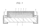
- FIG. 1 is a cross sectional view of an electrochromic mirror, illustrating the outline of an embodiment of the present invention.
- a preferred embodiment of the electrochromic mirror according to the present invention includes a configuration illustrated in FIG. 1 , for example.
- the electrochromic mirror includes a glass substrate 1 on a frontside. On the glass substrate 1, a transparent electrode film 2, an oxidation coloring film 3, a solid electrolyte film 4, a reduction coloring film 5, and an electrode/reflective film 6 are laminated in that order. To the electrode films 2 and 6, electrically conductive clips 8 and 9 are bonded, respectively, thus forming external power supply terminals.
- the thus formed electrochromic device includes a protective insulating layer 7 coated on an upper surface of the upper-most layer of the laminated body, i.e., the electrode/reflective film 6, and on laminated end faces of the films, including the electrically conductive clips.
- the frontside glass substrate 1 requires translucency as a normal mirror substrate.
- Representative examples of the material of the glass substrate 1 include various glasses, such as phosphorous silicate glass, soda-lime glass, and float glass.
- Another example of the transparent material for the substrate I with a protection function similar to glass is an appropriate synthetic resin material.
- the transparent electrically conductive film 2 is a film that functions as an electrode for applying voltage to the electrochromic device.
- an electrically conductive material with high transmittance is used. Specifically, metals such as gold, silver, platinum, or rhodium, or metal oxides such as ITO, SnO 2 , or ZnO may be used.
- a thin film of such material is formed in close contact with the glass plate as the surface substrate 1, by a well-known film forming process, such as ion plating.
- the thin film has a thickness of approximately 2000 ⁇ (200 nm), for example.
- the oxidation coloring film 3 is an oxidation coloring film disposed in contact with the transparent electrically conductive film 2.
- the oxidation coloring film 3 is colored or decolored, together with the reduction coloring film 5 described below, by exchanging protons with the adjacent electrolyte film upon turning on-off voltage to the electrochromic mirror.
- the material of the film may be in the form of a solution, a gel, or a solid. Preferably, a solid material may be used. Specific examples include IrO x , NiO x , RhO x , and Cr 2 O 3 .
- a thin film of such material is formed on the transparent electrode 2 in a laminated and closely contacted manner by a well-known film forming process, such as ion plating.
- the thin film has a thickness of approximately 1000 ⁇ , for example.
- the electrolyte film 4 is disposed in contact with the oxidation coloring film 3.
- the electrolyte film 4 causes the oxidation coloring film 3 and the reduction coloring film 5 to be colored or decolored by the oxidation/reduction reaction based on the exchange of protons produced by electrolysis of a small amount of water when the electrochromic mirror is energized.
- the electrolyte may come in the form of a solution, a gel, or a solid.
- a solid electrolyte is used. Specific examples include solid electrolytes that have electrical insulating property and ion conductivity, such as Ta 2 O 5 , Nb 2 O 5 , ZrO 2 , La 2 O 3 , LaNi 5 , and HfO 2 .
- a thin film of such material is formed between the reduction coloring film 3 and the reduction coloring film 5 in a laminated and closely contacted manner also by a well-known film forming process, such as ion plating.
- the thin film has a thickness of approximately 5000 ⁇ (500 nm), for example.
- the reduction coloring film 5 is a coloring film disposed in contact with the electrolyte film 4.
- the reduction coloring film 5 is colored or decolored through proton exchange, as in the case of the oxidation coloring film.
- the reduction coloring film 5 provides an anti-glare effect by mirror coloring, in combination with the coloring or decoloring of the oxidation coloring film 3.
- Specific examples of the material include metal oxides, such as WO 3 , MoO 3 , and V 2 O 5 .
- the reduction coloring film 5 is formed on the solid electrolyte film 4 in closely contacted manner by a well-known film forming process, such as electron beam vapor deposition, and has a thickness of approximately 5000 ⁇ (500 nm), for example.
- the electrode/reflective film 6 is a member that functions as a reflective film that reflects incident light that has passed through the electrochromic mirror toward the frontside glass substrate 1, and as another electrode film of the electrochromic device.
- the electrode/reflective film 6 is selected from materials with high surface reflectivity and high electrical conductivity. Specific examples include thin films of Al, Cr, and Ag.
- the protective insulating layer 7 has the function of protecting the electrochromic device by, for example, coating the outer surface of the electrode/reflective film 6 disposed in the upper-most layer of the electrochromic device.
- the protective insulating layer 7 is a characteristic layer of the present invention that replaces the backside glass substrate used in conventional electrochromic mirrors.
- the protective insulating layer 7 is formed from a fluorine copolymer resin that is soluble in solvent.
- the protective insulating layer 7 is formed by a normal coating process as a uniform coating film that covers the laminated end faces of the respective layers including the electrically conductive clip portions (electrically conductive members) 8 and 9 on the outer surface.
- fluorine resins contain extremely stable fluorine atoms bonded to the carbon atoms of a main chain. Thus, fluorine resins have excellent weather resistance, heat resistance, and resistance to chemicals. Fluorine resins are conventionally used for various purposes, such as in the form of a so-called super engineering resin.
- fluorine resins are insoluble to solvents, the use of fluorine resins for paint purposes is limited. However, it is known that some fluorine resins can be rendered soluble to solvents by forming a copolymer with another hydrocarbon monomer that is copolymerizable with a fluoromonomer and that is soluble to solvents. Paint-purpose resins using such copolymers have already been put into production.
- the present inventor focused attention on a fluorine resin paint including such a copolymer, and made an attempt to use a fluorine resin paint including the copolymer as a resin paint for forming the electrochromic mirror protection film, as described in an example below.
- the present inventor evaluated the resin paint by conducting tests to confirm various functions with regard to durability, the tests involving applying the resin paint to an actual electrochromic mirror.
- the fluorine resin coating film was shown to sufficiently satisfy the various functions required of the electrochromic mirror.
- the fluorine resin coating film proved superior to coating films that had been conventionally proposed, such as the urethane resin and acrylic resin described in Patent Document 1, in every respect of salt-water resistance test or waterproof test.
- a comprehensive evaluation of chemical resistance or environmental resistance also showed that the fluorine resin coating film has sufficient durability.
- the resin according to the present invention also proved superior in ion insulation property per se when compared with the oxide insulating film according to Patent Document 2, on which Al 2 O 3 or Ta 2 O 5 is vapor-deposited in an attempt to improve ion insulation property. Further, the resin according to the present invention does not require the complementary anticorrosion coating that may be implemented depending on cases in Patent Document 2.
- the resin according to the present invention can be provided with the comprehensive protection function including the above functions.
- fluoroolefin monomer in the solvent-soluble fluorine copolymer resin examples include chlorotrifluoroethylene, trifluoroethylene, and vinylidene fluoride, in addition to perfluoro alkyl expressed by (CF 2 CF 2 ) n CF 3 . Particularly, perfluoro alkyl monomer may be preferable.
- acrylate monomer copolymerizable with fluoroolefin monomer examples include acrylate monomer and methacrylate monomer, of which acrylate monomer may be preferable.
- acrylate monomer examples include various alkyl esters of acrylic acid, such as alkyl acrylate monomer.
- fluorine atoms of the fluoroolefin chain migrate to the surface. Thereby, it is believed, the intended protection function can be extremely effectively obtained on the frontside of the coating film.
- an anion such as OH-, Cl-, or SO 4 2-
- an anion such as OH-, Cl-, or SO 4 2-
- a polymer structure may be damaged.
- fluorine atoms are locally present on the surface with high density, and the penetrating ion attack is blocked by the intermolecular force of the atoms.
- the durability of the coating film can be maintained even in a high-temperature and high-humidity environment containing large amounts of such ions.
- the fluorine copolymer resin has the superior protection function due to the fluorine atoms in the fluoroolefin monomer.
- the fluorine copolymer resin lacks elasticity as a protection film because the material is rigid.
- the coating film may be easily damaged by cracking, for example, due to the lack of thermal elasticity.
- the hydrocarbon monomer When a hydrocarbon monomer that enables the formation of a cross-linked structure and that contains a functional group, such as an OH group or a silyl group, is present in the copolymer, the hydrocarbon monomer functions to provide the copolymer resin with elasticity.
- the hydrocarbon monomer containing an OH group or a silyl group may be incorporated into the copolymer resin according to the present invention in addition to the fluoroolefin monomer and the acrylate monomer, so as to provide elasticity providing durability against cold/hot cycles.
- examples of the comonomer that provide the elasticity exhibiting durability against cold/hot cycles include tetrafluoroethylene (TFE), hexafluoropropylene (HFP), perfluoro ethylene propylene (FEP), perfluoro alkoxyalkane (PFA), ethylene-tetrafluoroethylene (ETFE), tetrafluoroethylene (TFE), hexafluoropropylene (HFP), vinylidene fluoride (VF2), and ethylene-chlorotrifluoroethylene (ECTFE).
- TFE tetrafluoroethylene
- HFP hexafluoropropylene
- FEP perfluoro ethylene propylene
- PFA perfluoro alkoxyalkane
- ETFE ethylene-tetrafluoroethylene
- TFE tetrafluoroethylene
- HFP hexafluoropropylene
- VF2 vinylidene fluoride
- ECTFE ethylene
- PTFE polytetrafluoroethylene
- PVDF polyvinylidene fluoride
- PCTFE polychlorotrifluoroethylene
- PVF polyvinyl fluoride
- the coating film may have a thickness of approximately I ⁇ m or more. According to the example described below, the coating film may preferably have a thickness of 5 ⁇ m or more and most preferably 8 ⁇ m or more.
- a transparent electrode film with a transmittance of 90% or more and a sheet resistance value of 10 ⁇ / ⁇ or less was formed by vapor-depositing an ITO on a glass substrate to a film thickness of 2000 ⁇ by ion plating. Then, also by ion plating, an oxidation coloring film with a transmittance of 80% or more was formed by vapor deposition of IrO 2 + SnO 2 to a total film thickness of 1000 ⁇ (IrO 2 : 150 ⁇ , SnO 2 : 850 ⁇ ). Thereafter, also by ion plating, an electrolyte film with a transmittance of 90% or more was formed to a film thickness of 5000 ⁇ by vapor deposition of Ta 2 O 5 .
- a reduction coloring layer with a transmittance of 95% or more was formed by electron beam vapor deposition of WO 3 to a film thickness of 5000 ⁇ .
- a reflective/electrode film with a sheet resistivity of 10 ⁇ / ⁇ or more and a reflectivity of 90% or more was formed by vapor deposition, such as resistance heating vapor deposition process, of Al to a thickness of 1000 ⁇ .
- Electrically conductive clips were connected to the transparent electrode film and the reflective/electrode film respectively, thus forming external feeding terminals.
- an electrochromic device By thus laminating the layers on the glass substrate, an electrochromic device was formed.
- the laminated end faces of the respective layers, including the reflective/electrode film on the upper-most surface of the electrochromic device and the frontside glass substrate, and the electrically conductive clips were coated with a paint.
- the paint was a paint (DURASURF DS-3300 (registered trademark) fluorine coating agent from Harves Co., Ltd.) including a solvent-soluble fluorine copolymer resin (hereafter referred to as "the fluorine copolymer resin") including a copolymer of perfluoro alkyl monomer and alkyl acrylate monomer, dissolved in butyl acetate (or fluorine solvent) (single coat when the paint had 30% fluorine concentration; double coats when the paint had 10% fluorine concentration).
- the paint was allowed to dry and solidify, whereby an electrochromic mirror was fabricated.
- the film thickness was variously set in a range of 0.1 ⁇ m to 30 ⁇ m depending on various test items as will be described below.
- An electrochromic mirror was fabricated in the same way as in the example with the exception that a conventional insulating urethane resin and acrylic resin were used as paints for the protective insulating layer, instead of the fluorine copolymer resin.
- Another electrochromic mirror was also fabricated as another comparative example.
- Al 2 O 3 for the protective insulating layer was vapor-deposited by ion plating to film thicknesses of 100, 200, and 300 nm (1000, 2000, and 3000 ⁇ ).
- the electrochromic mirrors fabricated as described above according to the example of the present invention and the comparative examples were evaluated.
- the evaluation initially involved tests regarding breakdown resistance (salt water resistance), moisture-proof property, and chemical resistance as representative functions.
- the evaluation also involved verifying environmental resistance regarding the antiglare performance of the electrochromic mirror, by conducting tests in terms of various items such as change in reflectivity, and color loss or blurring in the appearance of the mirror display.
- a wiring board including a copper pattern with a slit width of 200 ⁇ m was coated with the fluorine copolymer resin according to the example.
- the wiring board was also coated with the insulating urethane resin according to the comparative examples. After drying for one hour or more at room temperature, 3 mL of 5% saline solution was delivered by drops to a slit portion. A DC voltage of 18 V to 19 V was applied to both sides of the pattern.
- the fluorine copolymer resin according to the example of the present invention provides far greater resistance to salt water breakdown compared with the insulating urethane resin according to the comparative examples.
- the insulation resistance of the resin coating film according to the example of the present invention provides an excellent effect at the film thickness of 5 ⁇ m or more.
- the function significantly increased when the film thickness was around 8 ⁇ m or above.
- Water permeability was verified under conditions according to JIS-Z-0208 (40°C, 90%RH).
- Water permeability g / m 2 / 24 h Amount of water permeated in 24 hours [Table 2]
- Insulating film material Insulating urethane resin Acrylic resin Fluorine copolymer resin Film thickness 3 ⁇ m 10 ⁇ m 3 ⁇ m 10 ⁇ m 1 ⁇ m 3 ⁇ m 10 ⁇ m 20 ⁇ m
- the fluorine copolymer resin coating film according to the example provides superior moisture-proof property to the moisture-proof properties of the urethane resin and the acrylic resin when the film thickness is 1 ⁇ m.
- the water permeation level was decreased to approximately 1/7 to 1/15 as a whole.
- B Water repellency was maintained in a range of not less than 60% and less than 90%; no change in coating film appearance was observed.
- C Water repellency was maintained in a range of not less than 40% and less than 60%; no change in coating film appearance was observed.
- D Change in appearance, such as peeling, dissolution, discoloration, or cracking was observed.
- the characteristics of the electrochromic mirrors were evaluated in terms of the difference (reflectivity range) between decolored reflectivity and colored reflectivity that represents the anti-glare effect, and the results are shown in Table 4. After the various tests, the electrochromic mirror was observed for defects such as film peeling, reflective film corrosion, color loss or blurring in appearance, and these were also used as evaluation references.
- the change in reflectivity as reflective performance was satisfactory in the case of the coating film thickness of 100 nm (0.1 ⁇ m) to 10000 nm (10 ⁇ m).
- the coating film thickness of 10 nm to 200 nm corrosion of the reflective film due to pinhole, or color loss or blurring at the time of coloring was recognized.
- the film thickness was 8000 nm (8 ⁇ m) or more, no such defects were recognized.
- the urethane resin coating layer produced no problem in the tests of the various items with respect to the reflectivity range of reflective performance. However, in the salt water spray test, corrosion developed from the outer periphery of the Al reflective film, and the layer was evaluated to be unfit as a protection layer.
- the results of the experiments show that in the electrochromic mirror of which the protective insulating layer is formed by using the fluorine copolymer resin according to the present invention as a coating film, reflective performance is not decreased by various environmental variations, and an excellent anti-glare effect can be obtained when the coating film thickness is 8 ⁇ m or more. Further, the protective insulating layer can be easily formed by a simple coating process.
Landscapes
- Physics & Mathematics (AREA)
- Nonlinear Science (AREA)
- General Physics & Mathematics (AREA)
- Optics & Photonics (AREA)
- Engineering & Computer Science (AREA)
- Chemical & Material Sciences (AREA)
- Crystallography & Structural Chemistry (AREA)
- Multimedia (AREA)
- Mechanical Engineering (AREA)
- Mathematical Physics (AREA)
- Electrochromic Elements, Electrophoresis, Or Variable Reflection Or Absorption Elements (AREA)
- Laminated Bodies (AREA)
Abstract
Description
- The present invention relates to electrochromic mirrors. Particularly, the present invention relates to an electrochromic mirror in which a protective insulating synthetic resin layer is used as a protective base material for protecting an electrochromic device of the electrochromic mirror from an external environment in which the electrochromic mirror is used. The protective insulating synthetic resin layer provides an excellent comprehensive protective feature including various environmental resistances indispensable to an electrochromic mirror. The protective insulating synthetic resin layer is lightweight, and can be easy produced and processed.
- For example, in a rear view mirror for a motor vehicle, an electrochromic mirror has been put into practical use as an automobile rear-view mirror for preventing glare in night driving or the like. The electrochromic mirror includes a coloring film and an electrolyte film, which are disposed between a frontside (visible side) substrate and a backside (reflective side) substrate of the mirror. The coloring film is colored/decolored by oxidation/reduction reaction. The electrolyte film exchanges proton (H+) with the coloring film. In the electrochromic mirror, protons are supplied to or drawn from chromogenic materials at the time of turning on-off voltage to color/decolor the chromogenic materials. As a result, the reflectivity of the mirror can be varied. Thus, the electrochromic mirror prevents glare from an image reflecting on the surface of the mirror.
- In such a conventional electrochromic mirror, in addition to the glass substrate on the frontside of the mirror, a glass substrate for protecting the electrochromic device is disposed on the backside opposite to the glass substrate on the frontside of the mirror, for providing the mirror with the properties of insulation, waterproof/moisture-proof, anticorrosion, abrasion resistance, and the like against various kinds of factors of degradation of the electrochromic mirror due to the usage environment.
- The composite glass substrate as described above is advantageous in that the glass offers comprehensive protection against various environmental factors of degradation of the electrochromic device. However, the composite glass substrate is not a flexible material, and therefore not readily producible or processable. The composite glass substrate is also associated with the risk of damage by stress or shock. Further, because the glass substrate is heavy in weight. Thus, if the glass substrate is mounted to the body of a vehicle in a cantilever fashion, the entire glass substrate is subjected to large vibrations during driving. Thus, a structure is required to compensate for the disadvantage that the vibrations make it difficult for the driver to view the mirror reflective surface.
- Hence, it has been proposed to use a synthetic resin material, which is lighter and more easily processable, as the backside substrate, which does not require transparency, instead of the common glass and to cover the electrochromic device with a resin-coating layer (see Patent Document 1). The resin coating is lighter than glass. A uniform, highly adhesive protection coating can be formed at necessary portions of the device by simple coating.
- However, in the electrochromic mirror that utilizes the coloring reaction by ion exchange, it is particularly necessary to suppress the entry of ions that exist in the atmosphere as the operating environment. In the electrochromic device, when a voltage is applied to an electrolyte film, a small amount of water present in the electrolyte film undergoes hydrolysis, resulting in migration of cations (protons) in the electrochromic layer. As a result, for example, the following oxidation/reduction reactions are caused in the coloring film.
<Electrochromic film> <When decolored> <When colored> (1) Oxidation coloring film IrnOx, film: Ir(OH)n + xOH- ←→ Ir(OH)n+x + xe- (2) Solid electrolyte film Ta2O5 film: Ta2O5 + xH2O ←→ Ta2O5 + xH++xOH- (3) Reduction coloring film WO3 film: WO3 + xH+ + xe- ←→ HxWO3 - In the above reactions, H+ ion (proton) exchange takes place in each coloring film. Further, by the turning on-off voltage to the electrolyte film, the coloring or decoloring reaction by oxidation/reduction is repeated. When, for example, a cation contained in the atmosphere, such as Na+, enters the electrochromic device, the proton conductivity is decreased, whereby the reactions are disadvantageously inhibited. As a result, the expected anti-glare effect cannot be obtained.
- In
Patent Document 1, the density of an organic silicon or urethane polymer used as a synthetic resin material is increased by a cross-linked structure. Further, the resin film contains metal oxide, ceramic, or glass powder so as to prevent the entry of ions into the electrochromic device. However, the resultant effect is not necessarily sufficient. - The present inventor has previously proposed using an ion insulating metal oxide film of Al2O3 or Ta2O5, for example, as the backside base material of the electrochromic mirror (see Patent Document 2) so as to prevent the entry of ions in the atmosphere into the electrochromic device. The ion insulating oxide film can reliably prevent the entry of Na+ ions and the like present in the atmosphere into the mirror by the metal oxide, such as Al2O3 or Ta2O5. Such metal oxide film can be formed in the same vapor deposition apparatus and by the same process, such as vapor deposition, as used for forming an electrode film, an oxdation--reduction coloring film, an electrolyte film, or a reflective layer of the electrochromic device, by changing only the conditions. Thus, the metal oxide films are advantageous from the manufacturing process point of view.
-
- Patent Document 1:
JP-A-2000-2895 - Patent Document 2:
JP-A-2005-99606 - However, depending on the film thickness of such as oxide, the electrochromic mirror described in
Patent Document 2 may elute water-absorbing WO3 from the end face of the laminated layers due to water entering via a pinhole in the oxide. As a result, the inherent coloring reaction may be interfered, or corrosion of Al in the reflective film may occur. Thus, it is desired to further coat the entire electrochromic device with a waterproof/anticorrosion layer, for example. - In view of the problems discussed above, the present invention provides an electrochromic mirror such that the entire electrochromic device can be further covered with a waterproof/anticorrosive protection film, and such that the protection film can be easily formed.
- The present inventor conducted experiments and researches on various synthetic resin materials for the base material for external coating of the electrochromic mirror. Specifically, the inventor searched for synthetic resins that comprehensively provide various inherent protection functions with respect to properties of the usage environment, such as electrical insulation, ion insulation, water/humidity resistance, chemical resistance, heat resistance, and mechanical strength, and that renders itself to reliable formation of a coating film for a protective insulating layer over an entire surface of the electrochromic mirror through a simple coating operation process.
- During the search for materials for the protective insulating layer of the electrochromic mirror, the present inventor focused attention on fluorine resins with excellent properties for weather resistance, heat resistance, chemical resistance, and so on. Most fluorine resins are insoluble to solvents, and do not render themselves to easy coating in the form of a solution. Some of copolymers of a fluorine monomer and another copolymerizable monomer that is easily soluble in solvent are known to be solvable in solvent and are being used for paint applications. However, the base material for coating the electrochromic mirror needs to satisfy various usage environment conditions inherent to the intended use thereof, as described above, in addition to having solubility in solvent.
- The present inventor has studied the solvent-soluble fluorine resins in search of a fluorine resin that satisfies the various characteristics required of the protective insulating layer for the electrochromic mirror at practical levels. The experiments and researches conducted by the present inventor led to a specific fluorine copolymer resin that satisfies the requirements, and the present invention was made.
- In an electrochromic mirror according to the present invention, layers constituting an electrochromic device are successively laminated on a frontside glass substrate. Further, a reflective-film side on a rear side opposite to the frontside glass substrate is coated with a protective insulating layer. An outer surface of the electrochromic device is coated with a fluorine copolymer resin paint as the protective insulating layer. The fluorine copolymer resin paint includes a copolymer of a fluoroolefin monomer and an acrylate monomer that forms a solvent-soluble copolymer by copolymerizing with the fluoroolefin monomer.
- Preferably, in the fluorine copolymer resin according to the present invention, the fluoroolefin monomer may be a perfluoro alkyl monomer, and the acrylate monomer may be an alkyl acrylate monomer.
- According to the present invention, all of external surfaces including laminated end faces of the respective laminated films may be covered with the protective insulating layer.
- Preferably, according to the present invention, the electrochromic mirror may include an electrically conductive member disposed at an outer edge of the laminated end faces, the electrically conductive member providing an electrode for the electrode/reflective film and the transparent electrode film. Preferably, the electrically conductive member and the laminated end faces may be coated with the protective insulating layer.
- Preferably, according to the present invention, the protective insulating layer may have a coating thickness of I µm or more.
- The fluorine copolymer resin of the solvent-soluble fluoroolefin-acrylate copolymer is soluble in a normal solvent. The solution can be easily coated on the outer surface of the electrochromic device to form a uniformly coated film. In the coating film, fluorine atoms of the fluoro alkyl monomer is locally present in the coated film surface at high density due to the surface mobility of the atoms. Thus, the entry of water, salt content, various chemical substance, ions, or the like from the atmosphere into the electrochromic device can be adequately prevented.
- The assumed environmental factors that may degrade the electrochromic mirror are varied, including water, humidity, salt water, various chemical agents, cold/hot cycles, applied voltage, and mechanical shock, as described above. The influence of the factors on the electrochromic mirror may appear in the form of defects, such as a decrease in reflective performance, corrosion or peeling of the constituent films, and elution of chromogenic material.
- According to the present invention, the electrochromic mirror is fabricated using the solvent-soluble, specific fluorine copolymer resin in the protective insulating layer. As will be described with reference to an example below, an experiment was conducted, assuming various cases in which the environment factors act on the electrochromic mirror. As a result, it has been confirmed that the influence on the durability of the electrochromic mirror can be prevented in each case at practically permissible level.
- In the tests, specific film thicknesses of the protective insulating film for obtaining a sufficient effect on each item is determined. Then, based on the determined film thicknesses, an electrochromic mirror with excellent reflective usage environment resistance can be provided.
- The fluorine copolymer resin in which the fluoroolefin monomer is a perfluoro alkyl monomer and the acrylate monomer is an alkyl acrylate monomer has higher solubility to solvent and therefore enables the formation of a uniform and dense coating layer readily. The resultant protective insulating layer satisfies various protection functions for electrochromic mirror applications in a practical manner.
- As described above, the protective insulating layer according to the present invention provides satisfactory coating property. Thus, when the electrically conductive members as power supply terminals are deposed on the external surfaces including the laminated end faces of the constituent layers of the mirror and on the laminated end faces, the protective insulating layer according to the present invention can cover all the external surfaces thereof and can be coated with the protective insulating layer in a satisfactory manner. Namely, the entire mirror can be completely coated with the protective insulating layer and thereby protected.
- When the film thickness of the coating layer as the protective insulating layer is 1 µm or more, the coating layer can provide a sufficient protection function.
-
FIG. 1 is a cross sectional view of an electrochromic mirror, illustrating the outline of an embodiment of the present invention. - A preferred embodiment of the electrochromic mirror according to the present invention includes a configuration illustrated in
FIG. 1 , for example. - The electrochromic mirror includes a
glass substrate 1 on a frontside. On theglass substrate 1, atransparent electrode film 2, an oxidation coloring film 3, asolid electrolyte film 4, areduction coloring film 5, and an electrode/reflective film 6 are laminated in that order. To theelectrode films conductive clips 8 and 9 are bonded, respectively, thus forming external power supply terminals. The thus formed electrochromic device includes a protectiveinsulating layer 7 coated on an upper surface of the upper-most layer of the laminated body, i.e., the electrode/reflective film 6, and on laminated end faces of the films, including the electrically conductive clips. - The
frontside glass substrate 1 requires translucency as a normal mirror substrate. Representative examples of the material of theglass substrate 1 include various glasses, such as phosphorous silicate glass, soda-lime glass, and float glass. Another example of the transparent material for the substrate I with a protection function similar to glass is an appropriate synthetic resin material. - The transparent electrically
conductive film 2 is a film that functions as an electrode for applying voltage to the electrochromic device. For the transparent electricallyconductive film 2, an electrically conductive material with high transmittance is used. Specifically, metals such as gold, silver, platinum, or rhodium, or metal oxides such as ITO, SnO2, or ZnO may be used. - A thin film of such material is formed in close contact with the glass plate as the
surface substrate 1, by a well-known film forming process, such as ion plating. The thin film has a thickness of approximately 2000 Å (200 nm), for example. - The oxidation coloring film 3 is an oxidation coloring film disposed in contact with the transparent electrically
conductive film 2. The oxidation coloring film 3 is colored or decolored, together with thereduction coloring film 5 described below, by exchanging protons with the adjacent electrolyte film upon turning on-off voltage to the electrochromic mirror. The material of the film may be in the form of a solution, a gel, or a solid. Preferably, a solid material may be used. Specific examples include IrOx, NiOx, RhOx, and Cr2O3. - A thin film of such material is formed on the
transparent electrode 2 in a laminated and closely contacted manner by a well-known film forming process, such as ion plating. The thin film has a thickness of approximately 1000 Å, for example. - The
electrolyte film 4 is disposed in contact with the oxidation coloring film 3. Theelectrolyte film 4 causes the oxidation coloring film 3 and thereduction coloring film 5 to be colored or decolored by the oxidation/reduction reaction based on the exchange of protons produced by electrolysis of a small amount of water when the electrochromic mirror is energized. By varying the amount of light that is passed through the electrochromic mirror, an anti-glare effect is provided by a difference in reflectivity when decolored and when colored. The electrolyte may come in the form of a solution, a gel, or a solid. According to the present invention, a solid electrolyte is used. Specific examples include solid electrolytes that have electrical insulating property and ion conductivity, such as Ta2O5, Nb2O5, ZrO2, La2O3, LaNi5, and HfO2. - A thin film of such material is formed between the reduction coloring film 3 and the
reduction coloring film 5 in a laminated and closely contacted manner also by a well-known film forming process, such as ion plating. The thin film has a thickness of approximately 5000 Å (500 nm), for example. - The
reduction coloring film 5 is a coloring film disposed in contact with theelectrolyte film 4. Thereduction coloring film 5 is colored or decolored through proton exchange, as in the case of the oxidation coloring film. Thereduction coloring film 5 provides an anti-glare effect by mirror coloring, in combination with the coloring or decoloring of the oxidation coloring film 3. Specific examples of the material include metal oxides, such as WO3, MoO3, and V2O5. Thereduction coloring film 5 is formed on thesolid electrolyte film 4 in closely contacted manner by a well-known film forming process, such as electron beam vapor deposition, and has a thickness of approximately 5000 Å (500 nm), for example. - The electrode/
reflective film 6 is a member that functions as a reflective film that reflects incident light that has passed through the electrochromic mirror toward thefrontside glass substrate 1, and as another electrode film of the electrochromic device. The electrode/reflective film 6 is selected from materials with high surface reflectivity and high electrical conductivity. Specific examples include thin films of Al, Cr, and Ag. - A thin film of such material formed on the
reduction coloring film 5 in a laminated and closely contacted manner by a well-known film forming process, such as resistance heating vapor deposition, to a thickness of approximately 1000 Å (100 nm), for example. - The protective
insulating layer 7 has the function of protecting the electrochromic device by, for example, coating the outer surface of the electrode/reflective film 6 disposed in the upper-most layer of the electrochromic device. The protectiveinsulating layer 7 is a characteristic layer of the present invention that replaces the backside glass substrate used in conventional electrochromic mirrors. The protectiveinsulating layer 7 is formed from a fluorine copolymer resin that is soluble in solvent. The protectiveinsulating layer 7 is formed by a normal coating process as a uniform coating film that covers the laminated end faces of the respective layers including the electrically conductive clip portions (electrically conductive members) 8 and 9 on the outer surface. - Generally, fluorine resins contain extremely stable fluorine atoms bonded to the carbon atoms of a main chain. Thus, fluorine resins have excellent weather resistance, heat resistance, and resistance to chemicals. Fluorine resins are conventionally used for various purposes, such as in the form of a so-called super engineering resin.
- Because most fluorine resins are insoluble to solvents, the use of fluorine resins for paint purposes is limited. However, it is known that some fluorine resins can be rendered soluble to solvents by forming a copolymer with another hydrocarbon monomer that is copolymerizable with a fluoromonomer and that is soluble to solvents. Paint-purpose resins using such copolymers have already been put into production.
- As described above, there is a wide variety of usage environmental factors causing degradation of the electrochromic mirror. However, no cases are known in which the above-described fluorine resin paint is applied in the relevant field. Further, no light has been shed on the relationship between the environment factors and inherent defects of the mirror, such as a decrease in reflective function, color loss, or blurring. Thus, it is not easy to select a fluorine resin paint that has characteristics comprehensively satisfying all of the required various functions and that is relatively low-cost. In addition, it is not easy to evaluate the durability of each individual fluorine resin paint so as to use the resin for actual coating of the electrochromic mirror.
- It is relatively easy to copolymerize a fluoroolefin monomer and an acrylate monomer. It is also easy to increase the rate of introduction of fluorine atoms of the fluoroolefin monomer and the acrylate monomer, which is closely related to the protection function. The present inventor focused attention on a fluorine resin paint including such a copolymer, and made an attempt to use a fluorine resin paint including the copolymer as a resin paint for forming the electrochromic mirror protection film, as described in an example below. The present inventor evaluated the resin paint by conducting tests to confirm various functions with regard to durability, the tests involving applying the resin paint to an actual electrochromic mirror.
- As a result, the fluorine resin coating film was shown to sufficiently satisfy the various functions required of the electrochromic mirror. For example, the fluorine resin coating film proved superior to coating films that had been conventionally proposed, such as the urethane resin and acrylic resin described in
Patent Document 1, in every respect of salt-water resistance test or waterproof test. A comprehensive evaluation of chemical resistance or environmental resistance also showed that the fluorine resin coating film has sufficient durability. - The resin according to the present invention also proved superior in ion insulation property per se when compared with the oxide insulating film according to
Patent Document 2, on which Al2O3 or Ta2O5 is vapor-deposited in an attempt to improve ion insulation property. Further, the resin according to the present invention does not require the complementary anticorrosion coating that may be implemented depending on cases inPatent Document 2. The resin according to the present invention can be provided with the comprehensive protection function including the above functions. - Examples of the fluoroolefin monomer in the solvent-soluble fluorine copolymer resin include chlorotrifluoroethylene, trifluoroethylene, and vinylidene fluoride, in addition to perfluoro alkyl expressed by (CF2CF2)nCF3. Particularly, perfluoro alkyl monomer may be preferable.
- Examples of the acrylate monomer copolymerizable with fluoroolefin monomer include acrylate monomer and methacrylate monomer, of which acrylate monomer may be preferable. Preferable examples of acrylate monomer include various alkyl esters of acrylic acid, such as alkyl acrylate monomer.
- In these fluorine resins, fluorine atoms of the fluoroolefin chain migrate to the surface. Thereby, it is believed, the intended protection function can be extremely effectively obtained on the frontside of the coating film. When an anion, such as OH-, Cl-, or SO4 2-, externally acts on a polar group of the acrylate monomer that contains oxygen, a polymer structure may be damaged. However, in the present structure, fluorine atoms are locally present on the surface with high density, and the penetrating ion attack is blocked by the intermolecular force of the atoms. Thus, the durability of the coating film can be maintained even in a high-temperature and high-humidity environment containing large amounts of such ions.
- The fluorine copolymer resin has the superior protection function due to the fluorine atoms in the fluoroolefin monomer. However, the fluorine copolymer resin lacks elasticity as a protection film because the material is rigid. Further, when the fluorine copolymer resin is used in an environment in which cold/hot cycles with large temperature changes are repeated, the coating film may be easily damaged by cracking, for example, due to the lack of thermal elasticity.
- When a hydrocarbon monomer that enables the formation of a cross-linked structure and that contains a functional group, such as an OH group or a silyl group, is present in the copolymer, the hydrocarbon monomer functions to provide the copolymer resin with elasticity. Thus, the hydrocarbon monomer containing an OH group or a silyl group may be incorporated into the copolymer resin according to the present invention in addition to the fluoroolefin monomer and the acrylate monomer, so as to provide elasticity providing durability against cold/hot cycles. In addition to such monomers, examples of the comonomer that provide the elasticity exhibiting durability against cold/hot cycles include tetrafluoroethylene (TFE), hexafluoropropylene (HFP), perfluoro ethylene propylene (FEP), perfluoro alkoxyalkane (PFA), ethylene-tetrafluoroethylene (ETFE), tetrafluoroethylene (TFE), hexafluoropropylene (HFP), vinylidene fluoride (VF2), and ethylene-chlorotrifluoroethylene (ECTFE). Examples of copolymers that provide similar elasticity include polytetrafluoroethylene (PTFE), polyvinylidene fluoride (PVDF), polychlorotrifluoroethylene (PCTFE), and polyvinyl fluoride (PVF) copolymers. Any of these may be present in the copolymer.
- When the protective insulating layer is formed, a coating film with sufficient protection function can be obtained by a single film forming process, instead of coating multiple layers as according to a conventional coating technique. The coating film may have a thickness of approximately I µm or more. According to the example described below, the coating film may preferably have a thickness of 5 µm or more and most preferably 8 µm or more.
- A transparent electrode film with a transmittance of 90% or more and a sheet resistance value of 10Ω/□ or less was formed by vapor-depositing an ITO on a glass substrate to a film thickness of 2000 Å by ion plating. Then, also by ion plating, an oxidation coloring film with a transmittance of 80% or more was formed by vapor deposition of IrO2 + SnO2 to a total film thickness of 1000 Å (IrO2: 150 Å, SnO2: 850 Å). Thereafter, also by ion plating, an electrolyte film with a transmittance of 90% or more was formed to a film thickness of 5000 Å by vapor deposition of Ta2O5. On the electrolyte film, a reduction coloring layer with a transmittance of 95% or more was formed by electron beam vapor deposition of WO3 to a film thickness of 5000 Å. Over, and in contact with, the reduction coloring layer, a reflective/electrode film with a sheet resistivity of 10Ω/□ or more and a reflectivity of 90% or more was formed by vapor deposition, such as resistance heating vapor deposition process, of Al to a thickness of 1000 Å. Electrically conductive clips were connected to the transparent electrode film and the reflective/electrode film respectively, thus forming external feeding terminals.
- By thus laminating the layers on the glass substrate, an electrochromic device was formed. The laminated end faces of the respective layers, including the reflective/electrode film on the upper-most surface of the electrochromic device and the frontside glass substrate, and the electrically conductive clips were coated with a paint. The paint was a paint (DURASURF DS-3300 (registered trademark) fluorine coating agent from Harves Co., Ltd.) including a solvent-soluble fluorine copolymer resin (hereafter referred to as "the fluorine copolymer resin") including a copolymer of perfluoro alkyl monomer and alkyl acrylate monomer, dissolved in butyl acetate (or fluorine solvent) (single coat when the paint had 30% fluorine concentration; double coats when the paint had 10% fluorine concentration). The paint was allowed to dry and solidify, whereby an electrochromic mirror was fabricated. In this case, the film thickness was variously set in a range of 0.1 µm to 30 µm depending on various test items as will be described below.
- An electrochromic mirror was fabricated in the same way as in the example with the exception that a conventional insulating urethane resin and acrylic resin were used as paints for the protective insulating layer, instead of the fluorine copolymer resin. Another electrochromic mirror was also fabricated as another comparative example. In these electrochromic mirrors, Al2O3 for the protective insulating layer was vapor-deposited by ion plating to film thicknesses of 100, 200, and 300 nm (1000, 2000, and 3000 Å).
- The electrochromic mirrors fabricated as described above according to the example of the present invention and the comparative examples were evaluated. The evaluation initially involved tests regarding breakdown resistance (salt water resistance), moisture-proof property, and chemical resistance as representative functions. The evaluation also involved verifying environmental resistance regarding the antiglare performance of the electrochromic mirror, by conducting tests in terms of various items such as change in reflectivity, and color loss or blurring in the appearance of the mirror display.
- A wiring board including a copper pattern with a slit width of 200 µm was coated with the fluorine copolymer resin according to the example. The wiring board was also coated with the insulating urethane resin according to the comparative examples. After drying for one hour or more at room temperature, 3 mL of 5% saline solution was delivered by drops to a slit portion. A DC voltage of 18 V to 19 V was applied to both sides of the pattern.
- The application of voltage was continued until the saline solution was completely dried, and the amount of electricity supplied was confirmed with a current meter. When the current exceeded 1000 µA, breakdown was considered to have occurred, and the test was terminated.
[Table 1] Insulating film material Insulating urethane resin Fluorine copolymer resin Film thickness 5 to 8 µm 10 to 20 µm 5 to 8 µm 10 to 20 µm 20 to 30 µm Time before breakdown Instantaneous 3 sec 4 min 150 min 180 min Maximum current value 1000 µA or more 1000 µA or more 650 µA 2.0 µA 0.7 µA - As shown in Table 1, for the same film thickness, the fluorine copolymer resin according to the example of the present invention provides far greater resistance to salt water breakdown compared with the insulating urethane resin according to the comparative examples.
- It is noted that the insulation resistance of the resin coating film according to the example of the present invention provides an excellent effect at the film thickness of 5 µm or more. The function significantly increased when the film thickness was around 8 µm or above.
- Water permeability was verified under conditions according to JIS-Z-0208 (40°C, 90%RH).

[Table 2] Insulating film material Insulating urethane resin Acrylic resin Fluorine copolymer resin Film thickness 3 µm 10 µm 3 µm 10 µm 1 µm 3 µm 10 µm 20 µm Water permeability 880 300 720 230 320 105 19 0 - As shown in Table 2, the fluorine copolymer resin coating film according to the example provides superior moisture-proof property to the moisture-proof properties of the urethane resin and the acrylic resin when the film thickness is 1 µm. At the various film thicknesses, the water permeation level was decreased to approximately 1/7 to 1/15 as a whole.
- Thermal conduction was compared between when coated with the protective insulating layer according to the example and when not coated, on the assumption that the electrochromic mirror is fitted with an anti-fog/frost heater. As a result, hardly any difference in thermal conductivity was recognized between the two cases. Thus, it was determined that the protective insulating layer according to the present invention does not produce any substantial problem even in the case of a heater-equipped mirror.
- Chemical resistance of the insulating film (perfluoro acrylic copolymer resin) was verified with respect to reagents used or beverages corresponding to various degradation factors that can be expected to affect the electrochromic mirror electrode due to the usage environment.
- The verification was based on water repellency and changes in the appearance of the coating film after immersion in supplied reagent products for 360 hours.
[Table 3] No. Assumed mode Reagent name Thickness of protective insulating film (µm) 0.1 0.5 2.0 6.0 10 20 1 Acidic rain 10% sulfuric acid D C C B B A 2 Bird dropping 5% caustic soda D C C B B B 3 Indoor drinking/eating Orange juice C C C B B A 4 Cola C C C B B A 5 Green tea C C B B B A 6 Li battery drive Lithium battery electrolyte D C C B B A 7 Coat of paint Toluene C C C B B B 8 Oily hand Olein acid D C C B B B 9 Assembly line Mineral oil C C B B B B 10 Mirror surface stain removal I.P.A C C C B A A 11 Ethanol C C C B A A 12 Acetone C C C B B B 13 Vehicle maintenance Engine oil C C B B B B 14 Battery fluid D C C B B A 15 Rain water Pure water C C B B B A A = 90% or more water repellency was maintained; no change in coating film appearance was observed.
B = Water repellency was maintained in a range of not less than 60% and less than 90%; no change in coating film appearance was observed.
C = Water repellency was maintained in a range of not less than 40% and less than 60%; no change in coating film appearance was observed.
D = Change in appearance, such as peeling, dissolution, discoloration, or cracking was observed. - As shown in Table 3, when the film thickness of the fluorine copolymer resin according to the example was 6 µm or more, practical-level chemical resistance was obtained with respect to the supplied reagent products and the like corresponding to the assumed degradation factors due to the usage environment.
- Changes in the characteristics (reflectivity difference) of the electrochromic mirrors according to the example and the comparative examples with respect to the environment were measured before and after tests of various items including temperature, high-temperature/high-humidity, dew condensation, immersion in warm water, salt water spray, and cold/hot cycle.
- The characteristics of the electrochromic mirrors were evaluated in terms of the difference (reflectivity range) between decolored reflectivity and colored reflectivity that represents the anti-glare effect, and the results are shown in Table 4. After the various tests, the electrochromic mirror was observed for defects such as film peeling, reflective film corrosion, color loss or blurring in appearance, and these were also used as evaluation references.
[Table 4] Major item Item Specimen Alumina sample 1 Alumina sample 2 Alumina sample 3 Urethane sample Fluorine resin sample F1 Fluorine resin sample F2 Fluorine resin sample F3 Fluorine resin sample F4 Sample spec Insulated spec film thickness alumina film formation 100 nm alumina film formation 200 nm alumina film formation 300 nm anticorrosion coat of paint fluorine resin coat 100 nm fluorine resin coat 200 nm fluorine resin coat 8000 nm fluorine resin coat 1600 0 nm Initial Decolored reflectivity 69.7 68.9 70.1 67.5 71.7 70.1 70.4 71.8 Colored reflectivity 9.8 8.3 8.8 8.8 8.8 9.1 9.6 9.2 Reflectivity range 59.9 60.6 61.3 58.7 62.9 61.0 60.8 62.6 After left standing in high-temperature Decolored reflectivity 65.7 64.2 69.6 67.8 71.1 70.3 70.5 71.4 Colored 20.8 17.6 9.1 8.8 9.1 9.2 9.2 9.0 reflectivity Reflectivity range 44.9 46.6 60.5 59.0 62.0 61.1 61.3 62.4 After left standing in low-temperature Decolored reflectivity 65.9 65.9 69.6 67.6 71.1 70.3 70.5 71.8 Colored reflectivity 19.4 15.3 9.3 8.8 9.3 8.9 9.4 9.0 Reflectivity range 46.5 50.6 60.3 58.8 61.8 61.4 61.1 62.8 After cold/hot cycle Decolored reflectivity 65.7 64.9 69.4 67.5 70.8 70.1 70.7 71.6 Colored reflectivity 21.8 17.2 9.8 8.8 9.3 8.8 9.2 9.2 Reflectivity range 43.9 47.7 59.6 58.7 61.5 61.3 61.5 62.4 After dew condensation test Decolored reflectivity 67.7 65.3 69.1 67.5 70.8 69.5 70.4 71.1 Colored reflectivity 32.8 22.3 9.2 8.8 9.1 9.1 8.9 9.2 Reflectivity range 34.9 43.0 59.9 58.7 61.7 60.7 61.5 61.9 After warm water submersio n Decolored reflectivity 66.7 66.9 68.2 67.5 70.6 70.1 70.4 71.8 Colored reflectivity 36.8 25.4 9.1 8.8 9.3 9.1 8.6 9.2 Reflectivity range 29.9 41.5 59.1 58.7 61.3 61.0 61.8 62.6 After high-temp erature and high-humidity Decolored reflectivity 66.8 64.9 68.1 67.5 70.8 69.9 70.4 71.4 Colored reflectivity 34.4 33.3 10.6 9.8 9.6 8.8 8.9 9.2 Reflectivity range 32.4 31.6 57.5 57.7 61.2 61.1 61.5 62.2 Salt water spray Decolored reflectivity 66.4 65.7 67.2 67.5 70.5 70.0 70.4 71.1 Colored reflectivity 66.4 43.1 18.8 10.2 9.7 9.1 8.6 9.2 Reflectivity range 0.0 22.6 48.4 57.3 60.8 60.9 61.8 61.9 - The conditions of the test items shown in Table 4 are as follows:
- After left standing in high-temperature: Left standing in environment of temperature of 85°C for 240 hours or more.
- After left standing in low-temperature: Left standing in environment of temperature of -40°C for 240 hours or more.
- After cold/hot cycle: Left standing in temperature-cycling environment of temperatures between -40 and 80°C for 240 hours or more.
- After dew condensation test: Left standing in environment of temperature of 35°C and humidity of 95% after being left standing at temperature of -40°C for 2 hours.
- After warm water submersion: Immersed in warm water of 40°C for 240 hours or more.
- After left standing in high-temperature and high-humidity: Left standing in environment of temperature of 80°C and humidity of 95% for 240 hours or more.
- Salt water spray: Sprayed with salt water of temperature 35°C and concentration of 5 mass% for 960 hours or more.
- As shown in Table 4, the changes in reflectivity, mirror appearance, and the like of the electrochromic mirrors according to the example and the comparative examples between when decolored and when colored in the various environment tests are as follows.
- The change in reflectivity as reflective performance (difference between decolored reflectivity and colored reflectivity: reflectivity range) was satisfactory in the case of the coating film thickness of 100 nm (0.1 µm) to 10000 nm (10 µm). In the coating film thickness of 10 nm to 200 nm, corrosion of the reflective film due to pinhole, or color loss or blurring at the time of coloring was recognized. However, when the film thickness was 8000 nm (8 µm) or more, no such defects were recognized.
- In the Al2O3 vapor deposition film, when the film thickness was 0.1 to 0.2 µm, the reflectivity difference was decreased or eliminated in the high temperature/low-temperature shelf test, and reflective power was degraded.
- Even when the vapor deposition film thickness was 300 nm (0.3 µm), corrosion developed in the Al reflective film due to pinhole in the high-temperature and high-humidity test. Further, in the salt water test, the reflectivity range was decreased by elution of WO3, or hardly any reflectivity change was exhibited, thus failing to provide the anti-glare effect.
- The urethane resin coating layer produced no problem in the tests of the various items with respect to the reflectivity range of reflective performance. However, in the salt water spray test, corrosion developed from the outer periphery of the Al reflective film, and the layer was evaluated to be unfit as a protection layer.
- The results of the experiments show that in the electrochromic mirror of which the protective insulating layer is formed by using the fluorine copolymer resin according to the present invention as a coating film, reflective performance is not decreased by various environmental variations, and an excellent anti-glare effect can be obtained when the coating film thickness is 8 µm or more. Further, the protective insulating layer can be easily formed by a simple coating process.
-
- 1: Frontside substrate (glass substrate)
- 2: Transparent electrode film
- 3: Oxidation coloring film
- 4: Solid electrolyte film
- 5: Reduction coloring film
- 6: Reflective film/electrode film
- 7: Protective insulating layer
- 8, 9: Electrically conductive clip
Claims (5)
- An electrochromic mirror including a frontside substrate serving as a mirror surface in which a transparent electrode film, an oxidation coloring film, an electrolyte film, a reduction coloring film, an electrode/reflective film, and a protective insulating layer as a backside base material corresponding to the frontside substrate are successively laminated,
wherein:the protective insulating layer is a coating layer; andthe coating layer is formed of a fluorine copolymer resin including a copolymer of a fluoroolefin monomer and an acrylate monomer that forms a solvent-soluble copolymer by copolymerizing with the fluoroolefin monomer. - The electrochromic mirror according to claim 1,
wherein:the fluoroolefin monomer is a perfluoro alkyl monomer; andthe acrylate monomer is an alkyl acrylate monomer. - The electrochromic mirror according to claim 1 or 2, wherein all of an external surface including a laminated end face of each of the respective laminated films are covered with the protective insulating layer.
- The electrochromic mirror according to claim 3, further comprising an electrically conductive member disposed at an outer edge of the laminated end face, the electrically conductive member providing an electrode for the electrode/reflective film and the transparent electrode film,
wherein the electrically conductive member and the laminated end face are coated with the protective insulating layer. - The electrochromic mirror according to any one of claims 1 to 4, wherein the protective insulating layer has a coating thickness of 1 µm or more.
Applications Claiming Priority (2)
| Application Number | Priority Date | Filing Date | Title |
|---|---|---|---|
| JP2012047447A JP5612003B2 (en) | 2012-03-03 | 2012-03-03 | Electrochromic mirror |
| PCT/JP2012/076345 WO2013132688A1 (en) | 2012-03-03 | 2012-10-11 | Electrochromic mirror |
Publications (3)
| Publication Number | Publication Date |
|---|---|
| EP2746847A1 true EP2746847A1 (en) | 2014-06-25 |
| EP2746847A4 EP2746847A4 (en) | 2015-07-15 |
| EP2746847B1 EP2746847B1 (en) | 2016-05-25 |
Family
ID=49116192
Family Applications (1)
| Application Number | Title | Priority Date | Filing Date |
|---|---|---|---|
| EP12870593.6A Not-in-force EP2746847B1 (en) | 2012-03-03 | 2012-10-11 | Electrochromic mirror |
Country Status (5)
| Country | Link |
|---|---|
| US (1) | US20140226199A1 (en) |
| EP (1) | EP2746847B1 (en) |
| JP (1) | JP5612003B2 (en) |
| CN (1) | CN103842899B (en) |
| WO (1) | WO2013132688A1 (en) |
Families Citing this family (2)
| Publication number | Priority date | Publication date | Assignee | Title |
|---|---|---|---|---|
| JP6452734B2 (en) | 2014-06-17 | 2019-01-16 | セイジ・エレクトロクロミクス,インコーポレイテッド | Moisture resistant electrochromic device |
| CN108136962B (en) * | 2015-09-30 | 2021-06-29 | 金泰克斯公司 | full display mirror |
Family Cites Families (12)
| Publication number | Priority date | Publication date | Assignee | Title |
|---|---|---|---|---|
| JP2000002895A (en) | 1998-04-14 | 2000-01-07 | Murakami Corp | Sealing structure of all solid type electrochromic antidazzle mirror |
| ES2164029B1 (en) * | 2000-07-07 | 2003-05-16 | Fico Mirrors Sa | ELECTROCHROMICAL DEVICE AND CORRESPONDING APPLICATIONS. |
| CN1469912A (en) * | 2000-10-20 | 2004-01-21 | 大金工业株式会社 | Aqueous coating composition of fluorine-containing copolymer |
| EP1437621A1 (en) * | 2001-10-10 | 2004-07-14 | Murakami Corporation | Solid type electrochromic glare-proof mirror |
| JP4363939B2 (en) * | 2003-09-26 | 2009-11-11 | 株式会社ホンダロック | Electrochromic mirror |
| CN1980980A (en) * | 2004-05-07 | 2007-06-13 | 3M创新有限公司 | Fluoropolyether poly(meth)acryl compounds |
| JP4591036B2 (en) * | 2004-10-21 | 2010-12-01 | ブラザー工業株式会社 | Image display medium, electrophoretic display device, and method of manufacturing image display medium |
| JP2010009913A (en) * | 2008-06-26 | 2010-01-14 | Asahi Kasei E-Materials Corp | Photopolymerizable resin laminate, and method of manufacturing pattern using the same |
| JP2010055018A (en) * | 2008-08-29 | 2010-03-11 | Fuji Xerox Co Ltd | Display medium and method of manufacturing display medium |
| US9176474B2 (en) * | 2009-09-11 | 2015-11-03 | Daikin Industries, Ltd. | Light-concentrating film, method for producing same, focusing element, solar cell, and focusing method |
| JP5818298B2 (en) * | 2010-01-08 | 2015-11-18 | 国立研究開発法人産業技術総合研究所 | All-solid-state reflective dimming electrochromic element sealed with a protective layer and dimming member using the same |
| JP5750758B2 (en) * | 2011-04-08 | 2015-07-22 | 国立研究開発法人産業技術総合研究所 | All-solid-state reflective dimming electrochromic element having wavelength selectivity and dimming member using the same |
-
2012
- 2012-03-03 JP JP2012047447A patent/JP5612003B2/en active Active
- 2012-10-11 CN CN201280047278.3A patent/CN103842899B/en not_active Expired - Fee Related
- 2012-10-11 EP EP12870593.6A patent/EP2746847B1/en not_active Not-in-force
- 2012-10-11 WO PCT/JP2012/076345 patent/WO2013132688A1/en not_active Ceased
- 2012-10-11 US US14/346,836 patent/US20140226199A1/en not_active Abandoned
Also Published As
| Publication number | Publication date |
|---|---|
| JP5612003B2 (en) | 2014-10-22 |
| EP2746847A4 (en) | 2015-07-15 |
| JP2013182221A (en) | 2013-09-12 |
| CN103842899B (en) | 2017-03-08 |
| US20140226199A1 (en) | 2014-08-14 |
| CN103842899A (en) | 2014-06-04 |
| EP2746847B1 (en) | 2016-05-25 |
| WO2013132688A1 (en) | 2013-09-12 |
Similar Documents
| Publication | Publication Date | Title |
|---|---|---|
| US9397240B2 (en) | Corrosion resistant solar mirror | |
| RU2468404C2 (en) | Transparent layer with high electrical conductivity containing metal lattice with optimised electrochemical stability | |
| RU2411560C2 (en) | Electrode for electrochemical electro-drive devices | |
| US9949319B2 (en) | Pane having an electric heating layer | |
| EP2477810B1 (en) | Laminated glazing | |
| CN101322069B (en) | Transparent electrode for electrochromic conversion unit | |
| CA2879446C (en) | Composite pane with electrical contacting means | |
| CN103966560B (en) | The manufacture method of Infra Red reflective films | |
| ES2425843T3 (en) | Electric thermal glass panel, manufacturing procedure, as well as window | |
| US20140376075A1 (en) | Electrocontrollable device | |
| JP2008542804A5 (en) | ||
| EP3351717B1 (en) | Functional building material for windows and doors | |
| US9061481B2 (en) | Display-on-demand mirror with optional defogging feature, and method of making the same | |
| JPH02258655A (en) | Heat-radiation reflecting laminated plate | |
| CN103339560A (en) | Electrochemical devices with electrically controllable optical and/or energy transport properties | |
| EP2746847B1 (en) | Electrochromic mirror | |
| KR102167964B1 (en) | Heating element applicable to various substrates | |
| US20220086961A1 (en) | Transparent thin film heater with good moisture tolerance and mechanical properties comprising a transparent conducting oxide and the method for producing the same | |
| JP2732129B2 (en) | Superhydrophobic composite material, method for producing the same, and optical functional material | |
| EA036760B1 (en) | Method for supplying an electronic component of a laminated glazing unit with electrical power and laminated glazing unit for implementing said method | |
| Medwick et al. | Corrosion resistant solar mirror | |
| KR20070121704A (en) | Heated mirror | |
| KR20220164411A (en) | Transparent heater film and preparing method for the same | |
| JPH11323205A (en) | Paint for preventing corrosion of oxide semiconductor, liquid crystal display device coated with the paint, and heater for anti-fog and defrost |
Legal Events
| Date | Code | Title | Description |
|---|---|---|---|
| PUAI | Public reference made under article 153(3) epc to a published international application that has entered the european phase |
Free format text: ORIGINAL CODE: 0009012 |
|
| 17P | Request for examination filed |
Effective date: 20140318 |
|
| AK | Designated contracting states |
Kind code of ref document: A1 Designated state(s): AL AT BE BG CH CY CZ DE DK EE ES FI FR GB GR HR HU IE IS IT LI LT LU LV MC MK MT NL NO PL PT RO RS SE SI SK SM TR |
|
| DAX | Request for extension of the european patent (deleted) | ||
| RA4 | Supplementary search report drawn up and despatched (corrected) |
Effective date: 20150616 |
|
| RIC1 | Information provided on ipc code assigned before grant |
Ipc: G02F 1/153 20060101ALI20150610BHEP Ipc: G02F 1/161 20060101ALI20150610BHEP Ipc: B60R 1/08 20060101ALI20150610BHEP Ipc: B32B 27/30 20060101AFI20150610BHEP |
|
| REG | Reference to a national code |
Ref country code: DE Ref legal event code: R079 Ref document number: 602012019090 Country of ref document: DE Free format text: PREVIOUS MAIN CLASS: G02F0001150000 Ipc: B32B0027300000 |
|
| GRAP | Despatch of communication of intention to grant a patent |
Free format text: ORIGINAL CODE: EPIDOSNIGR1 |
|
| RIC1 | Information provided on ipc code assigned before grant |
Ipc: G02F 1/161 20060101ALI20151111BHEP Ipc: B32B 27/30 20060101AFI20151111BHEP Ipc: B60R 1/08 20060101ALI20151111BHEP Ipc: G02F 1/153 20060101ALI20151111BHEP |
|
| INTG | Intention to grant announced |
Effective date: 20151216 |
|
| GRAS | Grant fee paid |
Free format text: ORIGINAL CODE: EPIDOSNIGR3 |
|
| GRAA | (expected) grant |
Free format text: ORIGINAL CODE: 0009210 |
|
| AK | Designated contracting states |
Kind code of ref document: B1 Designated state(s): AL AT BE BG CH CY CZ DE DK EE ES FI FR GB GR HR HU IE IS IT LI LT LU LV MC MK MT NL NO PL PT RO RS SE SI SK SM TR |
|
| REG | Reference to a national code |
Ref country code: GB Ref legal event code: FG4D |
|
| REG | Reference to a national code |
Ref country code: CH Ref legal event code: EP |
|
| REG | Reference to a national code |
Ref country code: IE Ref legal event code: FG4D Ref country code: AT Ref legal event code: REF Ref document number: 801927 Country of ref document: AT Kind code of ref document: T Effective date: 20160615 |
|
| REG | Reference to a national code |
Ref country code: DE Ref legal event code: R096 Ref document number: 602012019090 Country of ref document: DE |
|
| REG | Reference to a national code |
Ref country code: LT Ref legal event code: MG4D |
|
| REG | Reference to a national code |
Ref country code: NL Ref legal event code: MP Effective date: 20160525 |
|
| PG25 | Lapsed in a contracting state [announced via postgrant information from national office to epo] |
Ref country code: LT Free format text: LAPSE BECAUSE OF FAILURE TO SUBMIT A TRANSLATION OF THE DESCRIPTION OR TO PAY THE FEE WITHIN THE PRESCRIBED TIME-LIMIT Effective date: 20160525 Ref country code: NO Free format text: LAPSE BECAUSE OF FAILURE TO SUBMIT A TRANSLATION OF THE DESCRIPTION OR TO PAY THE FEE WITHIN THE PRESCRIBED TIME-LIMIT Effective date: 20160825 Ref country code: FI Free format text: LAPSE BECAUSE OF FAILURE TO SUBMIT A TRANSLATION OF THE DESCRIPTION OR TO PAY THE FEE WITHIN THE PRESCRIBED TIME-LIMIT Effective date: 20160525 Ref country code: NL Free format text: LAPSE BECAUSE OF FAILURE TO SUBMIT A TRANSLATION OF THE DESCRIPTION OR TO PAY THE FEE WITHIN THE PRESCRIBED TIME-LIMIT Effective date: 20160525 |
|
| REG | Reference to a national code |
Ref country code: AT Ref legal event code: MK05 Ref document number: 801927 Country of ref document: AT Kind code of ref document: T Effective date: 20160525 |
|
| PG25 | Lapsed in a contracting state [announced via postgrant information from national office to epo] |
Ref country code: PT Free format text: LAPSE BECAUSE OF FAILURE TO SUBMIT A TRANSLATION OF THE DESCRIPTION OR TO PAY THE FEE WITHIN THE PRESCRIBED TIME-LIMIT Effective date: 20160926 Ref country code: RS Free format text: LAPSE BECAUSE OF FAILURE TO SUBMIT A TRANSLATION OF THE DESCRIPTION OR TO PAY THE FEE WITHIN THE PRESCRIBED TIME-LIMIT Effective date: 20160525 Ref country code: LV Free format text: LAPSE BECAUSE OF FAILURE TO SUBMIT A TRANSLATION OF THE DESCRIPTION OR TO PAY THE FEE WITHIN THE PRESCRIBED TIME-LIMIT Effective date: 20160525 Ref country code: SE Free format text: LAPSE BECAUSE OF FAILURE TO SUBMIT A TRANSLATION OF THE DESCRIPTION OR TO PAY THE FEE WITHIN THE PRESCRIBED TIME-LIMIT Effective date: 20160525 Ref country code: GR Free format text: LAPSE BECAUSE OF FAILURE TO SUBMIT A TRANSLATION OF THE DESCRIPTION OR TO PAY THE FEE WITHIN THE PRESCRIBED TIME-LIMIT Effective date: 20160826 Ref country code: ES Free format text: LAPSE BECAUSE OF FAILURE TO SUBMIT A TRANSLATION OF THE DESCRIPTION OR TO PAY THE FEE WITHIN THE PRESCRIBED TIME-LIMIT Effective date: 20160525 |
|
| PG25 | Lapsed in a contracting state [announced via postgrant information from national office to epo] |
Ref country code: IT Free format text: LAPSE BECAUSE OF FAILURE TO SUBMIT A TRANSLATION OF THE DESCRIPTION OR TO PAY THE FEE WITHIN THE PRESCRIBED TIME-LIMIT Effective date: 20160525 |
|
| PG25 | Lapsed in a contracting state [announced via postgrant information from national office to epo] |
Ref country code: SK Free format text: LAPSE BECAUSE OF FAILURE TO SUBMIT A TRANSLATION OF THE DESCRIPTION OR TO PAY THE FEE WITHIN THE PRESCRIBED TIME-LIMIT Effective date: 20160525 Ref country code: CZ Free format text: LAPSE BECAUSE OF FAILURE TO SUBMIT A TRANSLATION OF THE DESCRIPTION OR TO PAY THE FEE WITHIN THE PRESCRIBED TIME-LIMIT Effective date: 20160525 Ref country code: EE Free format text: LAPSE BECAUSE OF FAILURE TO SUBMIT A TRANSLATION OF THE DESCRIPTION OR TO PAY THE FEE WITHIN THE PRESCRIBED TIME-LIMIT Effective date: 20160525 Ref country code: DK Free format text: LAPSE BECAUSE OF FAILURE TO SUBMIT A TRANSLATION OF THE DESCRIPTION OR TO PAY THE FEE WITHIN THE PRESCRIBED TIME-LIMIT Effective date: 20160525 Ref country code: RO Free format text: LAPSE BECAUSE OF FAILURE TO SUBMIT A TRANSLATION OF THE DESCRIPTION OR TO PAY THE FEE WITHIN THE PRESCRIBED TIME-LIMIT Effective date: 20160525 |
|
| PG25 | Lapsed in a contracting state [announced via postgrant information from national office to epo] |
Ref country code: BE Free format text: LAPSE BECAUSE OF FAILURE TO SUBMIT A TRANSLATION OF THE DESCRIPTION OR TO PAY THE FEE WITHIN THE PRESCRIBED TIME-LIMIT Effective date: 20160525 Ref country code: SM Free format text: LAPSE BECAUSE OF FAILURE TO SUBMIT A TRANSLATION OF THE DESCRIPTION OR TO PAY THE FEE WITHIN THE PRESCRIBED TIME-LIMIT Effective date: 20160525 Ref country code: PL Free format text: LAPSE BECAUSE OF FAILURE TO SUBMIT A TRANSLATION OF THE DESCRIPTION OR TO PAY THE FEE WITHIN THE PRESCRIBED TIME-LIMIT Effective date: 20160525 Ref country code: AT Free format text: LAPSE BECAUSE OF FAILURE TO SUBMIT A TRANSLATION OF THE DESCRIPTION OR TO PAY THE FEE WITHIN THE PRESCRIBED TIME-LIMIT Effective date: 20160525 |
|
| REG | Reference to a national code |
Ref country code: DE Ref legal event code: R097 Ref document number: 602012019090 Country of ref document: DE |
|
| PLBE | No opposition filed within time limit |
Free format text: ORIGINAL CODE: 0009261 |
|
| STAA | Information on the status of an ep patent application or granted ep patent |
Free format text: STATUS: NO OPPOSITION FILED WITHIN TIME LIMIT |
|
| 26N | No opposition filed |
Effective date: 20170228 |
|
| PG25 | Lapsed in a contracting state [announced via postgrant information from national office to epo] |
Ref country code: SI Free format text: LAPSE BECAUSE OF FAILURE TO SUBMIT A TRANSLATION OF THE DESCRIPTION OR TO PAY THE FEE WITHIN THE PRESCRIBED TIME-LIMIT Effective date: 20160525 |
|
| REG | Reference to a national code |
Ref country code: CH Ref legal event code: PL |
|
| GBPC | Gb: european patent ceased through non-payment of renewal fee |
Effective date: 20161011 |
|
| REG | Reference to a national code |
Ref country code: IE Ref legal event code: MM4A |
|
| REG | Reference to a national code |
Ref country code: FR Ref legal event code: ST Effective date: 20170630 |
|
| PG25 | Lapsed in a contracting state [announced via postgrant information from national office to epo] |
Ref country code: CH Free format text: LAPSE BECAUSE OF NON-PAYMENT OF DUE FEES Effective date: 20161031 Ref country code: LI Free format text: LAPSE BECAUSE OF NON-PAYMENT OF DUE FEES Effective date: 20161031 Ref country code: GB Free format text: LAPSE BECAUSE OF NON-PAYMENT OF DUE FEES Effective date: 20161011 Ref country code: FR Free format text: LAPSE BECAUSE OF NON-PAYMENT OF DUE FEES Effective date: 20161102 |
|
| PG25 | Lapsed in a contracting state [announced via postgrant information from national office to epo] |
Ref country code: LU Free format text: LAPSE BECAUSE OF NON-PAYMENT OF DUE FEES Effective date: 20161011 |
|
| PG25 | Lapsed in a contracting state [announced via postgrant information from national office to epo] |
Ref country code: IE Free format text: LAPSE BECAUSE OF NON-PAYMENT OF DUE FEES Effective date: 20161011 |
|
| PG25 | Lapsed in a contracting state [announced via postgrant information from national office to epo] |
Ref country code: HU Free format text: LAPSE BECAUSE OF FAILURE TO SUBMIT A TRANSLATION OF THE DESCRIPTION OR TO PAY THE FEE WITHIN THE PRESCRIBED TIME-LIMIT; INVALID AB INITIO Effective date: 20121011 |
|
| PG25 | Lapsed in a contracting state [announced via postgrant information from national office to epo] |
Ref country code: MT Free format text: LAPSE BECAUSE OF NON-PAYMENT OF DUE FEES Effective date: 20161031 Ref country code: IS Free format text: LAPSE BECAUSE OF FAILURE TO SUBMIT A TRANSLATION OF THE DESCRIPTION OR TO PAY THE FEE WITHIN THE PRESCRIBED TIME-LIMIT Effective date: 20160525 Ref country code: MK Free format text: LAPSE BECAUSE OF FAILURE TO SUBMIT A TRANSLATION OF THE DESCRIPTION OR TO PAY THE FEE WITHIN THE PRESCRIBED TIME-LIMIT Effective date: 20160525 Ref country code: CY Free format text: LAPSE BECAUSE OF FAILURE TO SUBMIT A TRANSLATION OF THE DESCRIPTION OR TO PAY THE FEE WITHIN THE PRESCRIBED TIME-LIMIT Effective date: 20160525 Ref country code: MC Free format text: LAPSE BECAUSE OF FAILURE TO SUBMIT A TRANSLATION OF THE DESCRIPTION OR TO PAY THE FEE WITHIN THE PRESCRIBED TIME-LIMIT Effective date: 20160525 Ref country code: HR Free format text: LAPSE BECAUSE OF FAILURE TO SUBMIT A TRANSLATION OF THE DESCRIPTION OR TO PAY THE FEE WITHIN THE PRESCRIBED TIME-LIMIT Effective date: 20160525 |
|
| PG25 | Lapsed in a contracting state [announced via postgrant information from national office to epo] |
Ref country code: BG Free format text: LAPSE BECAUSE OF FAILURE TO SUBMIT A TRANSLATION OF THE DESCRIPTION OR TO PAY THE FEE WITHIN THE PRESCRIBED TIME-LIMIT Effective date: 20160525 |
|
| PG25 | Lapsed in a contracting state [announced via postgrant information from national office to epo] |
Ref country code: TR Free format text: LAPSE BECAUSE OF FAILURE TO SUBMIT A TRANSLATION OF THE DESCRIPTION OR TO PAY THE FEE WITHIN THE PRESCRIBED TIME-LIMIT Effective date: 20160525 Ref country code: AL Free format text: LAPSE BECAUSE OF FAILURE TO SUBMIT A TRANSLATION OF THE DESCRIPTION OR TO PAY THE FEE WITHIN THE PRESCRIBED TIME-LIMIT Effective date: 20160525 |
|
| PGFP | Annual fee paid to national office [announced via postgrant information from national office to epo] |
Ref country code: DE Payment date: 20191001 Year of fee payment: 8 |
|
| REG | Reference to a national code |
Ref country code: DE Ref legal event code: R119 Ref document number: 602012019090 Country of ref document: DE |
|
| PG25 | Lapsed in a contracting state [announced via postgrant information from national office to epo] |
Ref country code: DE Free format text: LAPSE BECAUSE OF NON-PAYMENT OF DUE FEES Effective date: 20210501 |