EP2746617A1 - V-belt for transmitting high load - Google Patents
V-belt for transmitting high load Download PDFInfo
- Publication number
- EP2746617A1 EP2746617A1 EP13764791.3A EP13764791A EP2746617A1 EP 2746617 A1 EP2746617 A1 EP 2746617A1 EP 13764791 A EP13764791 A EP 13764791A EP 2746617 A1 EP2746617 A1 EP 2746617A1
- Authority
- EP
- European Patent Office
- Prior art keywords
- belt
- pulley
- center line
- thickness direction
- contact face
- Prior art date
- Legal status (The legal status is an assumption and is not a legal conclusion. Google has not performed a legal analysis and makes no representation as to the accuracy of the status listed.)
- Granted
Links
- 239000011295 pitch Substances 0.000 claims description 19
- 229920001971 elastomer Polymers 0.000 description 44
- 230000003014 reinforcing effect Effects 0.000 description 32
- 239000004744 fabric Substances 0.000 description 26
- 230000000052 comparative effect Effects 0.000 description 24
- 230000005540 biological transmission Effects 0.000 description 21
- 239000010410 layer Substances 0.000 description 20
- 239000000203 mixture Substances 0.000 description 19
- 239000000835 fiber Substances 0.000 description 9
- 229920005989 resin Polymers 0.000 description 8
- 239000011347 resin Substances 0.000 description 8
- 239000011247 coating layer Substances 0.000 description 7
- 239000004615 ingredient Substances 0.000 description 5
- OKTJSMMVPCPJKN-UHFFFAOYSA-N Carbon Chemical compound [C] OKTJSMMVPCPJKN-UHFFFAOYSA-N 0.000 description 4
- 150000008360 acrylonitriles Chemical class 0.000 description 3
- 229920006231 aramid fiber Polymers 0.000 description 3
- 229910052799 carbon Inorganic materials 0.000 description 3
- 238000013329 compounding Methods 0.000 description 3
- 229920001577 copolymer Polymers 0.000 description 3
- 238000004132 cross linking Methods 0.000 description 3
- 238000003780 insertion Methods 0.000 description 3
- 230000037431 insertion Effects 0.000 description 3
- 238000004898 kneading Methods 0.000 description 3
- 239000011159 matrix material Substances 0.000 description 3
- 239000011342 resin composition Substances 0.000 description 3
- 229920000049 Carbon (fiber) Polymers 0.000 description 2
- 239000004971 Cross linker Substances 0.000 description 2
- 229920002943 EPDM rubber Polymers 0.000 description 2
- 239000004593 Epoxy Substances 0.000 description 2
- VYPSYNLAJGMNEJ-UHFFFAOYSA-N Silicium dioxide Chemical compound O=[Si]=O VYPSYNLAJGMNEJ-UHFFFAOYSA-N 0.000 description 2
- 239000000853 adhesive Substances 0.000 description 2
- 230000001070 adhesive effect Effects 0.000 description 2
- 229910052782 aluminium Inorganic materials 0.000 description 2
- XAGFODPZIPBFFR-UHFFFAOYSA-N aluminium Chemical compound [Al] XAGFODPZIPBFFR-UHFFFAOYSA-N 0.000 description 2
- 239000004760 aramid Substances 0.000 description 2
- 239000004917 carbon fiber Substances 0.000 description 2
- 239000004568 cement Substances 0.000 description 2
- 238000011156 evaluation Methods 0.000 description 2
- 230000020169 heat generation Effects 0.000 description 2
- 238000010438 heat treatment Methods 0.000 description 2
- 239000012948 isocyanate Substances 0.000 description 2
- 150000002513 isocyanates Chemical class 0.000 description 2
- 238000004519 manufacturing process Methods 0.000 description 2
- 238000000034 method Methods 0.000 description 2
- 229920001778 nylon Polymers 0.000 description 2
- 239000005011 phenolic resin Substances 0.000 description 2
- 238000010058 rubber compounding Methods 0.000 description 2
- 239000000126 substance Substances 0.000 description 2
- PIMBTRGLTHJJRV-UHFFFAOYSA-L zinc;2-methylprop-2-enoate Chemical compound [Zn+2].CC(=C)C([O-])=O.CC(=C)C([O-])=O PIMBTRGLTHJJRV-UHFFFAOYSA-L 0.000 description 2
- 239000003963 antioxidant agent Substances 0.000 description 1
- 229920003235 aromatic polyamide Polymers 0.000 description 1
- 239000006229 carbon black Substances 0.000 description 1
- 150000001732 carboxylic acid derivatives Chemical class 0.000 description 1
- 230000008878 coupling Effects 0.000 description 1
- 238000010168 coupling process Methods 0.000 description 1
- 238000005859 coupling reaction Methods 0.000 description 1
- 239000003431 cross linking reagent Substances 0.000 description 1
- 230000003247 decreasing effect Effects 0.000 description 1
- 239000000806 elastomer Substances 0.000 description 1
- 239000003822 epoxy resin Substances 0.000 description 1
- 239000000463 material Substances 0.000 description 1
- 229910052751 metal Inorganic materials 0.000 description 1
- 239000002184 metal Substances 0.000 description 1
- 239000007769 metal material Substances 0.000 description 1
- VNWKTOKETHGBQD-UHFFFAOYSA-N methane Chemical compound C VNWKTOKETHGBQD-UHFFFAOYSA-N 0.000 description 1
- 238000000465 moulding Methods 0.000 description 1
- 239000004014 plasticizer Substances 0.000 description 1
- 229920002239 polyacrylonitrile Polymers 0.000 description 1
- 229920000647 polyepoxide Polymers 0.000 description 1
- 238000003825 pressing Methods 0.000 description 1
- 239000012744 reinforcing agent Substances 0.000 description 1
- 150000003839 salts Chemical class 0.000 description 1
- 238000007493 shaping process Methods 0.000 description 1
- 230000035939 shock Effects 0.000 description 1
- 239000000377 silicon dioxide Substances 0.000 description 1
- 229920001187 thermosetting polymer Polymers 0.000 description 1
- 238000004073 vulcanization Methods 0.000 description 1
- 239000002759 woven fabric Substances 0.000 description 1
- XKMZOFXGLBYJLS-UHFFFAOYSA-L zinc;prop-2-enoate Chemical compound [Zn+2].[O-]C(=O)C=C.[O-]C(=O)C=C XKMZOFXGLBYJLS-UHFFFAOYSA-L 0.000 description 1
- 239000004711 α-olefin Substances 0.000 description 1
Images






Classifications
-
- F—MECHANICAL ENGINEERING; LIGHTING; HEATING; WEAPONS; BLASTING
- F16—ENGINEERING ELEMENTS AND UNITS; GENERAL MEASURES FOR PRODUCING AND MAINTAINING EFFECTIVE FUNCTIONING OF MACHINES OR INSTALLATIONS; THERMAL INSULATION IN GENERAL
- F16G—BELTS, CABLES, OR ROPES, PREDOMINANTLY USED FOR DRIVING PURPOSES; CHAINS; FITTINGS PREDOMINANTLY USED THEREFOR
- F16G5/00—V-belts, i.e. belts of tapered cross-section
- F16G5/16—V-belts, i.e. belts of tapered cross-section consisting of several parts
- F16G5/18—V-belts, i.e. belts of tapered cross-section consisting of several parts in the form of links
-
- F—MECHANICAL ENGINEERING; LIGHTING; HEATING; WEAPONS; BLASTING
- F16—ENGINEERING ELEMENTS AND UNITS; GENERAL MEASURES FOR PRODUCING AND MAINTAINING EFFECTIVE FUNCTIONING OF MACHINES OR INSTALLATIONS; THERMAL INSULATION IN GENERAL
- F16G—BELTS, CABLES, OR ROPES, PREDOMINANTLY USED FOR DRIVING PURPOSES; CHAINS; FITTINGS PREDOMINANTLY USED THEREFOR
- F16G5/00—V-belts, i.e. belts of tapered cross-section
- F16G5/16—V-belts, i.e. belts of tapered cross-section consisting of several parts
- F16G5/166—V-belts, i.e. belts of tapered cross-section consisting of several parts with non-metallic rings
Definitions
- the present disclosure relates to V-belts for transmitting high load.
- a V-belt including a plurality of blocks aligned in a belt length direction and endless tension bands on which each of the blocks is fasten is known as a V-belt for transmitting high load for use in a belt-type continuously variable transmission of an automobile, an agricultural machine, a general purpose machine, etc. (See, for example,
- Patent Document 1
- PATENT DOCUMENT 1 Japanese Unexamined Patent Publication No. 2011-236994
- the present disclosure relates to a belt for transmitting high load.
- the belt includes: two endless tension bands extending in pairs parallel to each other in a belt length direction and each including a cord which is buried therein and extends in a spiral having pitches in a belt width direction; and a plurality of blocks arranged along the two tension bands and each having fitting sections which each open on a corresponding one of both block side faces of each of the blocks, wherein one of the two tension bands is fitted into corresponding ones of the fitting sections which open on the block side faces located on a side, the other of the two tension bands is fitted into corresponding ones of the fitting sections which open on the block side faces located on the other side, in each of the blocks, a portion of each block side face located on and above the corresponding fitting section serves as an upper pulley-contact face whereas a portion of each block side face located on and below the corresponding fitting section serves as a lower pulley-contact face, and on each block side face of the blocks, a ratio of a dimension extending in a belt
- FIGS. 1-3 illustrate a V-belt C for transmitting high load according to an embodiment of the present disclosure.
- the V-belt C for transmitting high load of this embodiment can be used in a belt-type continuously variable transmission of an automobile, an agricultural machine, and a general purpose machine, for example.
- the V-belt C of this embodiment includes a pair of endless tension bands 10 and a plurality of blocks 20.
- the two tension bands 10 extend parallel to each other in a belt length direction.
- the plurality of blocks 20 are arranged at regular pitches and at intervals along the two tension bands 10, and fastened on the two tension bands 10.
- the V-belt C of this embodiment has a belt length of 480-750 mm, a belt pitch width of 20-30 mm, a maximum belt thickness of 9.0-17.0 mm, and is equipped with 96-375 pieces of the blocks 20.
- the blocks 20 are arranged at arrangement pitches of 2-5 mm and at intervals of 0.01-0.5 mm.
- FIG. 4A and 4B illustrate the tension band 10.
- Each tension band 10 has an endless flat band shape.
- a side face has upper and lower portions which have been chamfered to slope, and the other side face is oblique.
- Each tension band 10 has upper fitting recesses 11 formed on the upper face.
- the upper fitting recesses 11, which are grooves having a substantially bracket-shaped cross section and extending in a belt width direction, are arranged at regular pitches in the belt length direction.
- Each tension band 10 also has lower fitting recesses 12 formed on the lower face and corresponding to the upper fitting recesses 11.
- the lower fitting recesses 12, which are grooves having an arc-shaped cross section and extending in the belt width direction, are arranged at regular pitches in the belt length direction.
- Each tension band 10 has, e.g., a length of 480-750 mm, a width of 6-13 mm, and a thickness of 1.0-5.0 mm (preferably 1.5-3.0 mm).
- the thinnest portions between the bottoms of the upper fitting recesses 11 and the bottoms of the lower fitting recesses 12 have a thickness t 1 of 0.606-3.0 mm (preferably 0.606-1.5 mm).
- Each tension band 10 includes a tension band body made of a shape-retaining rubber layer 13.
- a cord 14 which extends in a spiral having pitches in the belt width direction is buried at a substantially middle in the belt thickness direction of the shape-retaining rubber layer 13.
- An upper reinforcing fabric 15 is adhered to the shape-retaining rubber layer 13 to cover an outside-facing surface of the layer 13.
- a lower reinforcing fabric 16 is adhered to the shape-retaining rubber layer 13 to cover an inside-facing surface of the layer 13.
- the tension bands 10 may include only the shape-retaining rubber layer 13 and the cord 14 without being provided with the upper reinforcing fabric 15 and the lower reinforcing fabric 16.
- the shape-retaining rubber layer 13 is made of a rubber composition cross-linked with a cross-linker and produced by heating and pressing a non-crosslinked rubber composition prepared by kneading a rubber component blended with various rubber compounding ingredients.
- the rubber component examples include hydrogenated acrylonitrile rubber (H-NBR); and ethylene- ⁇ -olefin elastomers such as ethylene propylene copolymer (EPR), ethylene-propylene-diene terpolymer (EPDM), ethylene-octene copolymer, and ethylene-butene copolymer.
- the rubber component may be hydrogenated acrylonitrile rubber (H-NBR) which is reinforced by addition of metal salts of an unsaturated carboxylic acid such as zinc dimethacrylate and zinc diacrylate.
- the rubber component may be made of either a single substance or a mixture of two or more substances.
- the compounding ingredients include vulcanization accelerators, plasticizer, reinforcing agents such as silica and carbon black, antioxidants, co-cross-linking agents, cross-linkers, and short fibers.
- the cord 14 includes a twisted yarn or a braid which is made of high-strength fibers such as aramid fibers, PBO fibers, or carbon fibers, and to which adhesion treatment has been applied.
- the cord 14 is made of a bundle of filaments of 800-1200 dtex, and has an outer diameter of 0.5-1.4 mm.
- the adhesion treatment of the cord 14 includes: a first treatment step in which the twisted yarn or the braid is immersed in, e.g., an epoxy solution or an isocyanate solution, and heated thereafter; and a second treatment step in which the twisted yarn or the braid is immersed in an RFL solution and heated thereafter.
- a third treatment step in which the twisted yarn or the braid is immersed in a rubber cement and dried thereafter may be performed. However, the third treatment step is preferably omitted.
- Each of the upper reinforcing fabric 15 and the lower reinforcing fabric 16 is made of woven, knitted, or unwoven fabric of aramid fibers or nylon fibers, and produced in the following manner.
- a first treatment step the woven, knitted, or unwoven fabric is immersed in an epoxy solution or an isocyanate solution, and heated thereafter.
- a second treatment step the woven, knitted, or unwoven fabric is immersed in an RFL solution and heated thereafter.
- a third step in which the woven, knitted, or unwoven fabric is immersed in or coated with a rubber cement and dried thereafter is performed as necessary.
- Each of the upper reinforcing fabric 15 and the lower reinforcing fabric 16 has a thickness of 0.2-0.4 mm for example.
- FIGS. 5A and 5B illustrate the block 20.
- Each of the blocks 20 is a plate member having a trapezoidal shape of which the upper base is longer than the lower base in a plan view.
- Each block 20 has a shape similar to a horizontally oriented "H.”
- each block 20 has slit-like fitting sections 21 each having an opening on a corresponding one of the block side faces facing each other along the belt width direction.
- each block 20 includes a portion located on and above the corresponding fitting section 21 and having a uniform thickness, and a portion located on and below the fitting section 21 and having a thickness decreasing downward.
- the portions located on and above the fitting sections 21 serve as upper pulley-contact faces 22 and the portions located on and below the fitting sections 21 serve as lower pulley-contact faces 23.
- An angle formed by both block side faces of each block 20, i.e., a belt angle, is 20-28° for example.
- Each of the fitting sections 21 of each block 20 extends horizontally from its innermost part to the opening located on the block side face, and has a uniform clearance.
- An upper fitting projection 24 which is a rib extending in the belt width direction and having a substantially rectangular cross section is formed on an upper surface of each fitting section 21.
- a lower fitting projection 25 which is a rib extending in the belt width direction and having a substantially arc-shaped cross section is formed on a lower surface of each fitting section 21.
- the innermost part of each fitting section 21 is defined by a sloping surface which continues from the upper surface and slopes inward, and another surface which continues from the sloping surface and slopes outward to the lower surface.
- Each fitting section 21 has the clearance t 2 ranging from 0.6 mm to 2.8 mm (preferably from 0.6 mm to 1.4 mm) in the belt thickness direction, and a depth in the belt width direction, i.e., an insertion width w of the tension band 10, ranging from 6 mm to 13 mm.
- Each block 20 has, on a front face, an engaging projection 26 having a truncated cone shape and located at the middle between the two fitting sections 21.
- Each block 20 also has, on a back face, an engaging recess 27 located at the middle between the two fitting sections 21 in a corresponding manner.
- Each block 20 includes a reinforcing member 28 serving as a skeleton framework at the center, and a coating layer 29 covering a surface of the reinforcing member 28.
- the entire surface of the reinforcing member 28 is not necessarily covered with the coating layer 29. It is sufficient that the coating layer 29 covers at least both block side faces serving as the pulley-contact faces (i.e. the upper and lower pulley-contact faces 22 and 23) and the portions to be in contact with the tension bands 10 (i.e., the upper and lower fitting projections 24 and 25).
- the other portions of the surface of the reinforcing member 28 may be exposed.
- the reinforcing member 28 has a shape similar to a horizontally oriented "H.” Specifically, the reinforcing member 28 includes upper and lower beams 28a and 28b which extend in the belt width direction, and a center pillar 28c which extends vertically and connects center portions of the beams 28a and 28b.
- the reinforcing member 28 is made of a metal material such as aluminum.
- the coating layer 29 is made of a short fiber-reinforced resin composition which is prepared by, e.g., kneading a matrix resin blended with short fibers and a resin compounding ingredient.
- the matrix resin include thermosetting resins such as a phenol resin and an epoxy resin.
- the matrix resin may be made of either a single resin or a combination of two or more resins.
- the short fibers include carbon short fibers such as polyacrylonitrile-based carbon short fibers and pitch-based carbon short fibers, and para-aramid short fibers.
- the resin compounding ingredients include graphite powder.
- the tension bands 10 are fitted into the fitting sections 21 of the plurality of blocks 20, thereby coupling the blocks 20 to one another.
- the tension bands 10 are each inserted into corresponding ones of the fitting sections 21 of the blocks 20 with the chamfered side face directed toward the innermost parts of the corresponding fitting sections 21 in a manner such that: the upper fitting projections 24 on the upper surfaces of the fitting sections 21 of the blocks 20 are fitted into the upper fitting recesses 11 on the upper face of the tension bands 10; the lower fitting projections 25 on the lower surfaces of the fitting sections 21 of the blocks 20 are fitted into the lower fitting recesses 12 on the lower face of the tension bands 10; and one of the side faces of each tension band 10 comes into contact with the innermost parts of the fitting sections 21.
- the plurality of blocks 20 are arranged at regular pitches and at intervals, and fastened on the two tension bands 10 extending parallel to each other in the belt length direction.
- the upper pulley-contact faces 22 and the lower pulley-contact faces 23 of the block side faces of the blocks 20 and the other side faces of each tension band 10 exposed to the outside together serve as the pulley-contact faces.
- the engaging projection 26 and the corresponding engaging recess 27 are engaged with each other.
- a dimension A extending in the belt thickness direction from the buried cord center line (i.e. the belt pitch line) of the corresponding tension band 10 to the lower end of the upper pulley-contact face 22, i.e., to the lower end of the upper fitting projection 24 is 0.4-0.8 mm (preferably 0.4-0.5 mm) for example
- a dimension B extending in the belt thickness direction from the buried cord center line to the upper end of the upper pulley-contact face 22 is 3.1-3.8 mm (preferably 3.1-3.4 mm) for example.
- the ratio (B/A) of the dimension B to the dimension A is larger than or equal to 4.0. Further, a dimension G extending in the belt thickness direction from the buried cord center line to the middle of the upper pulley-contact face 22 is smaller than or equal to 2.3 mm.
- FIG. 7 The behavior of the blocks 20 is presumed to be as follows: As indicated by the brace X in FIG. 7 , when the blocks 20 enters a pulley, the upper pulley-contact faces 22 of both block side faces of the blocks 20 are first pressed by the pulley, and consequently, the blocks 20 are gradually inclined forward in the belt running direction. Then, after the upper pulley-contact faces 22, the lower pulley-contact faces 23, and the side faces of tension bands 10 are pressed by the pulley, the forward-inclined blocks 20 are restored to the original state about the buried cord center line as an axis, as indicated by the brace Y.
- the upper pulley-contact faces 22 slide on the pulley to generate heat, and the generated heat causes a loss leading to reduction of transmission efficiency.
- the V-belt C of this embodiment it is presumed as follows: Since the ratio B/A is larger than or equal to 4.0 and the dimension G is smaller than or equal to 2.3 mm as described above, sliding movement of the upper pulley-contact faces 22 on the pulley is alleviated, and accordingly, the loss is reduced and the transmission efficiency is improved.
- the ratio B/A is preferably larger than 4.0, more preferably larger than 6.25, and still more preferably larger than 8.5.
- the upper limit of the ratio B/A is not particularly defined, the upper limit is preferably smaller than or equal to 13, and more preferably smaller than or equal to 12.
- the dimension G is preferably less than 2.3 mm, and more preferably less than 2.2 mm.
- the lower limit of the dimension G is not particularly defined, the lower limit is preferably larger than or equal to 1.7 mm, and more preferably larger than or equal to 1.8 mm.
- a dimension A' extending in the belt thickness direction from the buried cord center line of the corresponding tension band 10 to the upper end of the lower pulley-contact face 23, i.e., to the upper end of the lower fitting projection 25 is 0.4-0.8 mm (preferably 0.4-0.5 mm) for example.
- a dimension B' extending in the belt thickness direction from the buried cord center line to the lower end of the lower pulley-contact face 23 is 3.1-4.0 mm (preferably 3.1-3.8 mm, and more preferably 3.1-3.4mm) for example.
- a dimension G' extending in the belt thickness direction from the buried cord center line to the middle of the lower pulley-contact face 23 is smaller than or equal to 2.3 mm for example.
- the ratio B'/A' is preferably larger than or equal to 4.0, and the dimension G' is preferably smaller than or equal to 2.3 mm.
- the ratio B'/A' is preferably larger than 4.0, more preferably larger than 6.25, and still more preferably larger than 8.5.
- the upper limit of the ratio B'/A' is not particularly defined, the upper limit is preferably smaller than or equal to 13, and more preferably smaller than or equal to 12.
- the dimension G' is preferably smaller than 2.3 mm, and more preferably smaller than 2.2 mm. Although the lower limit of the dimension G' is not particularly defined, the lower limit is preferably larger than or equal to 1.7 mm, and more preferably larger than or equal to 1.8 mm.
- the dimension A may be either larger or smaller than the dimension A', it is preferable that the dimension A is equal to the dimension A'.
- the dimension B may be either larger or smaller than the dimension B', it is preferable that the dimension B is equal to the dimension B'.
- the ratio B/A may be either larger or smaller than the ratio B'/A', it is preferable that the ratio B/A is equal to the ratio B'/A'.
- the dimension G may be either larger or smaller than the dimension G', it is preferable that the dimension G is equal to the dimension G'.
- the belt width W at the buried cord center line (i.e., the belt pitch width W) is, e.g., 20-30 mm in the belt width direction.
- the thickness t 1 between the upper and lower fitting recesses 11 and 12 of each tension band 10 is slightly larger than the clearance t 2 of the fitting sections 21 of the blocks 20. Accordingly, the tension bands 10 fitted into the fitting sections 21 of the blocks 20 are in a compressed state.
- An interference (t 1 - t 2 ) is, e.g., 0.006-0.150 mm.
- the tension bands 10 protrude from the block side faces of the blocks 20. With this configuration, shock caused when the V-belt C enters the pulley can be alleviated by the tension bands 10.
- a protruding dimension ⁇ d which is a protruding amount of each tension band 10 is, e.g., 0.02-0.25 mm whereas the insertion width w of each tension band 10 at the buried cord center line is, e.g., 6-13 mm, as described above.
- the protruding dimension ⁇ d can be easily measured by scanning the side faces of the V-belt C with a contour measuring device.
- FIGS. 8A and 8B illustrate a belt-type continuously variable transmission 30 in which the V-belt C for transmitting high load of this embodiment is used.
- the belt-type continuously variable transmission 30 includes a drive shaft 31 and a driven shaft 33 disposed in parallel with each other.
- a drive pulley 32 is disposed on the drive shaft 31, and a driven pulley 34 having substantially the same diameter as that of the drive pulley 32 is disposed on the driven shaft 33.
- the drive pulley 32 has a fixed sheave which is fixed on the drive shaft 31 in a non-slidable manner and rotates together with the drive shaft 31, and a movable sheave which is supported in a slidable manner, faces the fixed sheave, and rotates together with the drive shaft 31.
- the driven pulley 34 has a fixed sheave which is fixed on the driven shaft 33 in a non-slidable manner and rotates together with the driven shaft 33, and a movable sheave which is supported in a slidable manner, faces the fixed sheave, and rotates together with the driven shaft 33.
- a V-shaped groove is formed between the fixed sheave and the movable sheave.
- the V-belt C for transmitting high load is wrapped around the V-shaped groove of each pulley.
- Each of the drive pulley 32 and the driven pulley 34 is capable of varying a pulley pitch diameter in the range from 40 mm to 150 mm.
- the belt transmission 30 is configured such that a running speed of the V-belt C for transmitting high load can be changed by varying a belt wrapping diameter of the drive pulley 32 and a belt wrapping diameter of the driven pulley 34. Specifically, when the movable sheave is brought close to the fixed sheave in the drive pulley 32 and the movable sheave is brought away from the fixed sheave in the driven pulley 34, the belt wrapping diameter of the drive pulley 32 becomes larger than that of the driven pulley 34, as shown in FIG. 8A . Consequently, the V-belt C is caused to run at a high speed.
- V-belt C for transmitting high load of this embodiment A fabrication method of the V-belt C for transmitting high load of this embodiment will be described below.
- a rubber component is kneaded with a rubber kneading machine such as a Banbury mixer.
- the rubber component is blended with rubber compounding ingredients, and then, further kneaded.
- the resultant non-crosslinked rubber composition is formed in a sheet shape by using calender rolls.
- a twisted yarn or a braid is subjected to adhesion treatment, thereby preparing the cord 14.
- Woven, knitted, or unwoven fabric is subjected to adhesion treatment, thereby preparing the upper reinforcing fabric 15 and the lower reinforcing fabric 16.
- the lower reinforcing fabric 16 formed in a cylindrical shape is put to cover a cylindrical mold on which ribs having shapes corresponding to the lower fitting recesses 12 of the tension bands 10 and extending in the mold axial direction are arranged at regular pitches along the circumference of the mold.
- a predetermined number of layers of the sheet-shaped non-crosslinked rubber composition are provided on the lower reinforcing fabric 16.
- the former corresponds to the belt length direction.
- the cylindrical mold is placed in a belt-fabricating device.
- the device is set to have inner temperature and pressure which allow the non-crosslinked rubber composition to be halfway through crosslinking, and maintained at the inner temperature and pressure during a predetermined period of time. In this period, the non-crosslinked rubber composition reaches a halfway stage of crosslinking, thereby shaping a lower half of the shape-retaining rubber layer 13. Also, the non-crosslinked rubber composition is caused to flow, and the ribs on the cylindrical mold press the lower reinforcing fabric 16, thereby forming the lower fitting recesses 12.
- the cylindrical mold is removed from the belt-fabricating device.
- the cord 14 is wound around the half crosslinked rubber composition at regular pitches, and a predetermined number of layers of the sheet-shaped non-crosslinked rubber composition are provided on the half crosslinked rubber composition having the cord 14 wound thereon.
- the upper reinforcing fabric 15 formed in a cylindrical shape is put on the layers of the sheet-shaped non-crosslinked rubber composition. At this time, either a grain direction or a contra-grain direction of the sheet-shaped non-crosslinked rubber composition may correspond to the belt length direction.
- a cylindrical sleeve is put on the outermost layer.
- ribs which have shapes corresponding to the upper fitting recesses 11 and extend in the axial direction are arranged at regular pitches along the circumference of the sleeve.
- the cylindrical mold having the above materials and the sleeve provided thereon is placed in the belt-fabricating device, which is set to have predetermined inner temperature and pressure and maintained at the predetermined inner temperature and pressure during a predetermined period of time.
- the non-crosslinked rubber composition is caused to flow, and the ribs on the sleeve press the upper reinforcing fabric 15, thereby forming the upper fitting recesses 11.
- crosslinking of the non-crosslinked rubber composition and the half-crosslinked rubber composition progresses, thereby forming the shape-retaining rubber layer 13.
- the adhesive on the surface of the cord 14 and the shape-retaining rubber layer 13 interdiffuse, and consequently, the cord 14 and the shape-retaining rubber layer 13 integrally adhere to each other.
- the adhesive attached to the upper and lower reinforcing fabrics 15 and 16 and the shape-retaining rubber layer 13 interdiffuse, and consequently, each of the upper and lower reinforcing fabrics 15 and 16 and the shape-retaining rubber layer 13 integrally adhere to each other. In this manner, a cylindrical slab is formed on the surface of the cylindrical mold.
- the cylindrical mold is removed from the belt-fabricating device.
- the cylindrical slab is removed from the circumferential surface of the mold, and then, sliced into band-shaped pieces having a predetermined width.
- the sliced pieces are subjected to chamfering, thereby producing the tension bands 10.
- the reinforcing member 28 is set into a cavity having the shape of the block, and clamped.
- a resin composition is injected into the cavity, and the cavity is cooled.
- the cavity is then opened to remove the block 20 that is a molding including the reinforcing member 28 covered with the coating layer 29 made of the resin composition.
- the block 20 is subjected to treatment such as heat treatment required to increase strength.
- One tension band 10 and the blocks 20 are positioned such that the upper and lower fitting recesses 11 and 12 respectively correspond to the upper and lower fitting projections 24 and 25 of the blocks 20.
- the tension band 10 is inserted into the fitting sections 21 on the same side of the blocks 20 such that the upper and lower fitting projections 24 and 25 are fitted into the upper and lower fitting recesses 11 and 12, thereby fastening the blocks 20 on the tension band 10.
- This operation is performed with respect to the entire circumference of the tension band 10 while causing the engaging projections 26 to engage with the engaging recesses 27 between the adjacent blocks 20.
- the other tension band 10 is inserted into the fitting sections 21 on the opposite side of the blocks 20.
- V-belts of Examples 1-3 and Comparative Examples 1-5 were fabricated.
- the configurations of the V-belts are also shown in Table 1.
- a V-belt for transmitting high load which is similar to the V-belt of the embodiment was fabricated. Specifically, on each block side face of the fabricated V-belt, the dimension A extending in the belt thickness direction from the buried cord center line of the corresponding tension band to the lower end of the upper pulley-contact face was 0.4 mm, whereas the dimension B extending in the belt thickness direction from the buried cord center line to the upper end of the upper pulley-contact face was 3.8 mm, and accordingly, the ratio (B/A) of the dimension B to the dimension A was 9.5. Further, a dimension G extending in the belt thickness direction from the buried cord center line to the middle of the upper pulley-contact face was 2.1 mm.
- This V-belt was a V-belt of Example 1.
- the V-belt for transmitting high load of Example 1 had a belt length of 492 mm, a belt width W at the buried cord center line of 20 mm, a maximum belt thickness of 12.8 mm, a belt angle of 26°, and included 164 pieces of blocks which were arranged at arrangement pitches of 3 mm and at intervals of 0.05 mm.
- the dimension A' extending in the belt thickness direction from the buried cord center line of the corresponding tension band to the upper end of the lower pulley-contact face was 0.4 mm
- the dimension B' extending in the belt thickness direction from the buried cord center line to the lower end of the lower pulley-contact face was 3.8 mm
- the ratio (B'/ A') of the dimension B' to the dimension A' was 9.5
- a dimension G' extending in the belt thickness direction from the buried cord center line to the middle of the lower pulley-contact face was 2.1 mm.
- Each of the tension bands included the shape-retaining rubber layer made of hydrogenated acrylonitrile rubber composition reinforced by addition of zinc dimethacrylate, the cord made of an aramid fiber braid, and the upper and lower reinforcing fabrics made of nylon fiber woven fabric.
- the reinforcing member of each block was made of aluminum, and the coating layer was made of a carbon fiber-containing phenol resin.
- a V-belt for transmitting high load of Example 2 was fabricated such that the V-belt had the same configuration as that of the V-belt of Example 1 except that: the dimensions A and A' were each 0.4 mm; the dimensions B and B' were each 3.1 mm; the ratio (B/A) of the dimension B to the dimension A and the ratio (B'/A') of the dimension B' to the dimension A' were each 7.8; and the dimensions G and G' were each 1.8 mm.
- a V-belt for transmitting high load of Example 3 was fabricated such that the V-belt had the same configuration as that of the V-belt of Example 1 except that: the dimensions A and A' were each 0.8 mm; the dimensions B and B' were each 3.8 mm; the ratio (B/A) of the dimension B to the dimension A and the ratio (B'/A') of the dimension B' to the dimension A' were each 4.8; and the dimensions G and G' were each 2.3 mm.
- a V-belt for transmitting high load of Example 4 was fabricated such that the V-belt had the same configuration as that of the V-belt of Example 1 except that: the dimension A' was 0.8 mm; the dimension B' was 4.0 mm; the ratio (B'/A') of the dimension B' to the dimension A' was 5.0; and the dimension G' was 2.4 mm.
- a V-belt for transmitting high load of Comparative Example 1 was fabricated such that the V-belt had the same configuration as that of the V-belt of Example 1 except that: the dimensions A and A' were each 0.8 mm; the dimensions B and B' were each 4.0 mm; the ratio (B/A) of the dimension B to the dimension A and the ratio (B'/A') of the dimension B' to the dimension A' were each 5.0; and the dimensions G and G' were each 2.4 mm.
- a V-belt for transmitting high load of Comparative Example 2 was fabricated such that the V-belt had the same configuration as that of the V-belt of Example 1 except that: the dimensions A and A' were each 1.4 mm; the dimensions B and B' were each 5.4 mm; the ratio (B/A) of the dimension B to the dimension A and the ratio (B'/A') of the dimension B' to the dimension A' were each 3.9; and the dimensions G and G' were each 3.4 mm.
- a V-belt for transmitting high load of Comparative Example 3 was fabricated such that the V-belt had the same configuration as that of the V-belt of Example 1 except that: the dimensions A and A' were each 1.4 mm; the dimensions B and B' were each 4.8 mm; the ratio (B/A) of the dimension B to the dimension A and the ratio (B'/A') of the dimension B' to the dimension A' were each 3.4; and the dimensions G and G' were each 3.1 mm.
- a V-belt for transmitting high load of Comparative Example 4 was fabricated such that the V-belt had the same configuration as that of the V-belt of Example 1 except that: the dimensions A and A' were each 1.1 mm; the dimensions B and B' were each 3.8 mm; the ratio (B/A) of the dimension B to the dimension A and the ratio (B'/A') of the dimension B' to the dimension A' were each 3.5; and the dimensions G and G' were each 2.5 mm.
- a V-belt for transmitting high load of Comparative Example 5 was fabricated such that the V-belt had the same configuration as that of the V-belt of Example 1 except that: the dimensions A and A' were each 1.4 mm; the dimensions B and B' were each 4.5 mm; the ratio (B/A) of the dimension B to the dimension A and the ratio (B'/A') of the dimension B' to the dimension A' were each 3.2; and the dimensions G and G' were each 3.0 mm.
- FIG. 9 illustrates a belt running test machine 90 which was used in belt running tests conducted to evaluate the below-described matters.
- the belt running test machine 90 included a drive pulley 91 and a driven pulley 92 which were installed in a chamber 93.
- Each of the V-belts C for transmitting high load of Examples 1-4 and Comparative Examples 1-5 was wrapped around the drive pulley 91 having a pulley pitch diameter (a diameter defined by the buried cord center line of the wrapped V-belt C) of 45.1 mm and the driven pulley 92 having a pulley pitch diameter of 110.8 mm.
- a deadweight (DW) of 1000 N was imposed on the driven pulley 92, and the drive pulley 91 was rotated with a drive shaft torque of 15N ⁇ m and at 5500 rpm while causing the chamber 93 to have an atmosphere at 25-35°C.
- the transmission efficiency was calculated according to the following formula: ((N 2 ⁇ Tr 2 ) / (N 1 ⁇ tr 1 )) ⁇ 100, where N 1 is an input rpm, N 2 is an output rpm, Tr 1 is an input torque, and Tr 2 is an output torque.
- each of the V-belts C for transmitting high load of Examples 1-4 and Comparative Examples 1-5 was wrapped around the drive pulley 91 and the driven pulley 92.
- a deadweight (DW) of 1000 N was imposed on the driven pulley 92, and the drive pulley 91 was rotated with a drive shaft torque of 15N ⁇ m and at 5500 rpm, while causing the chamber 93 to have an atmosphere at 65°C.
- the belt temperature of the V-belt C was measured at the belt backside by using a non-contact type thermometer.
- the transmission efficiency was as follows: Example 1, 98.2 %; Example 2, 98.0 %; Example 3, 98.0 %; Example 4, 97.2 %; Comparative Example 1, 95.0 %; Comparative Example 2, 91.0 %, Comparative Example 3, 92.0 %; Comparative Example 4, 93.5 %; and Comparative Example 5, 92.0 %.
- the belt temperature after a lapse of 15 minutes from the start of belt running was as follows: Example 1, 74.0°C; Example 2, 73.5°C; Example 3, 73.0°C; Example 4, 77.0°C; Comparative Example 1, 82.0°C; Comparative Example 2, 90.0°C; Comparative Example 3, 88.0°C; Comparative Example 4, 87.0°C; and Comparative Example 5, 88.0°C.
- FIG. 10A shows the relation between the ratio B/A and the transmission efficiency
- FIG. 10B shows the relation between the ratio B/A and the belt temperature
- FIG. 11A shows the relation between the dimension G and the transmission efficiency
- FIG. 11B shows the relation between the dimension G and the belt temperature.
- the present disclosure is useful for V-belts for transmitting high load.
Landscapes
- Engineering & Computer Science (AREA)
- General Engineering & Computer Science (AREA)
- Mechanical Engineering (AREA)
- Compositions Of Macromolecular Compounds (AREA)
- Transmissions By Endless Flexible Members (AREA)
- Belt Conveyors (AREA)
Abstract
Description
- The present disclosure relates to V-belts for transmitting high load.
- A V-belt including a plurality of blocks aligned in a belt length direction and endless tension bands on which each of the blocks is fasten is known as a V-belt for transmitting high load for use in a belt-type continuously variable transmission of an automobile, an agricultural machine, a general purpose machine, etc. (See, for example,
- PATENT DOCUMENT 1: Japanese Unexamined Patent Publication No.
2011-236994 - The present disclosure relates to a belt for transmitting high load. The belt includes: two endless tension bands extending in pairs parallel to each other in a belt length direction and each including a cord which is buried therein and extends in a spiral having pitches in a belt width direction; and a plurality of blocks arranged along the two tension bands and each having fitting sections which each open on a corresponding one of both block side faces of each of the blocks, wherein one of the two tension bands is fitted into corresponding ones of the fitting sections which open on the block side faces located on a side, the other of the two tension bands is fitted into corresponding ones of the fitting sections which open on the block side faces located on the other side, in each of the blocks, a portion of each block side face located on and above the corresponding fitting section serves as an upper pulley-contact face whereas a portion of each block side face located on and below the corresponding fitting section serves as a lower pulley-contact face, and on each block side face of the blocks, a ratio of a dimension extending in a belt thickness direction from a buried cord center line of the corresponding tension band to an upper end of the upper pulley-contact face to a dimension extending in the belt thickness direction from the buried cord center line to a lower end of the upper pulley-contact face is larger than or equal to 4.0, and a dimension extending in the belt thickness direction from the buried cord center line to a middle of the upper pulley-contact face is smaller than or equal to 2.3 mm.
-
- [
FIG. 1] FIG. 1 is a perspective view of a portion cut out from a V-belt for transmitting high load according to an embodiment of the present disclosure. - [
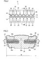
FIG. 2] FIG. 2 is a side view of a portion of the V-belt for transmitting high load according to the embodiment. - [
FIG. 3] FIG. 3 is a cross-sectional view taken along the line III-III inFIG. 2 . - [
FIG. 4] FIG. 4A is a side view of a tension band, andFIG. 4B is a cross-sectional view taken along the line IVB-IVB in theFIG. 4A . - [
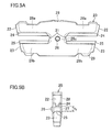
FIG. 5] FIGS. 5A and 5B are respectively a front view and a side view of a piece of the blocks. - [
FIG. 6] FIGS. 6A and 6B are respectively a partial cross-sectional view and a partial side view in which dimensions A, A', B, B', G, and G' of the V-belt of the embodiment are indicated. - [
FIG. 7] FIG. 7 illustrates behavior of the blocks. Specifically,FIG. 7 illustrates that the blocks having been inclined forward are restored to the original state. - [
FIG. 8] FIGS. 8A and 8B illustrate a pulley layout of a belt-type continuously variable transmission. - [
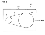
FIG. 9] FIG. 9 schematically illustrates a belt running test machine. - [
FIG. 10] FIG. 10A shows a relation between a ratio B/A and transmission efficiency, andFIG. 10B shows a relation between the ratio B/A and belt temperature. - [
FIG. 11] FIG. 11A shows a relation between the dimension G and the transmission efficiency, andFIG. 11B shows a relation between the dimension G and the belt temperature. - The present disclosure will be described below in detail with reference to the drawings.
-
FIGS. 1-3 illustrate a V-belt C for transmitting high load according to an embodiment of the present disclosure. The V-belt C for transmitting high load of this embodiment can be used in a belt-type continuously variable transmission of an automobile, an agricultural machine, and a general purpose machine, for example. - The V-belt C of this embodiment includes a pair of
endless tension bands 10 and a plurality ofblocks 20. The twotension bands 10 extend parallel to each other in a belt length direction. The plurality ofblocks 20 are arranged at regular pitches and at intervals along the twotension bands 10, and fastened on the twotension bands 10. The V-belt C of this embodiment has a belt length of 480-750 mm, a belt pitch width of 20-30 mm, a maximum belt thickness of 9.0-17.0 mm, and is equipped with 96-375 pieces of theblocks 20. Theblocks 20 are arranged at arrangement pitches of 2-5 mm and at intervals of 0.01-0.5 mm. -
FIG. 4A and 4B illustrate thetension band 10. - Each
tension band 10 has an endless flat band shape. In eachtension band 10, a side face has upper and lower portions which have been chamfered to slope, and the other side face is oblique. Eachtension band 10 hasupper fitting recesses 11 formed on the upper face. Theupper fitting recesses 11, which are grooves having a substantially bracket-shaped cross section and extending in a belt width direction, are arranged at regular pitches in the belt length direction. Eachtension band 10 also haslower fitting recesses 12 formed on the lower face and corresponding to theupper fitting recesses 11. Thelower fitting recesses 12, which are grooves having an arc-shaped cross section and extending in the belt width direction, are arranged at regular pitches in the belt length direction. Eachtension band 10 has, e.g., a length of 480-750 mm, a width of 6-13 mm, and a thickness of 1.0-5.0 mm (preferably 1.5-3.0 mm). In particular, the thinnest portions between the bottoms of theupper fitting recesses 11 and the bottoms of thelower fitting recesses 12 have a thickness t1 of 0.606-3.0 mm (preferably 0.606-1.5 mm). - Each
tension band 10 includes a tension band body made of a shape-retainingrubber layer 13. Acord 14 which extends in a spiral having pitches in the belt width direction is buried at a substantially middle in the belt thickness direction of the shape-retainingrubber layer 13. An upper reinforcingfabric 15 is adhered to the shape-retainingrubber layer 13 to cover an outside-facing surface of thelayer 13. A lower reinforcingfabric 16 is adhered to the shape-retainingrubber layer 13 to cover an inside-facing surface of thelayer 13. Thetension bands 10 may include only the shape-retainingrubber layer 13 and thecord 14 without being provided with the upper reinforcingfabric 15 and the lower reinforcingfabric 16. - The shape-retaining
rubber layer 13 is made of a rubber composition cross-linked with a cross-linker and produced by heating and pressing a non-crosslinked rubber composition prepared by kneading a rubber component blended with various rubber compounding ingredients. - Examples of the rubber component include hydrogenated acrylonitrile rubber (H-NBR); and ethylene-α-olefin elastomers such as ethylene propylene copolymer (EPR), ethylene-propylene-diene terpolymer (EPDM), ethylene-octene copolymer, and ethylene-butene copolymer. The rubber component may be hydrogenated acrylonitrile rubber (H-NBR) which is reinforced by addition of metal salts of an unsaturated carboxylic acid such as zinc dimethacrylate and zinc diacrylate. The rubber component may be made of either a single substance or a mixture of two or more substances. Examples of the compounding ingredients include vulcanization accelerators, plasticizer, reinforcing agents such as silica and carbon black, antioxidants, co-cross-linking agents, cross-linkers, and short fibers.
- The
cord 14 includes a twisted yarn or a braid which is made of high-strength fibers such as aramid fibers, PBO fibers, or carbon fibers, and to which adhesion treatment has been applied. For example, thecord 14 is made of a bundle of filaments of 800-1200 dtex, and has an outer diameter of 0.5-1.4 mm. - The adhesion treatment of the
cord 14 includes: a first treatment step in which the twisted yarn or the braid is immersed in, e.g., an epoxy solution or an isocyanate solution, and heated thereafter; and a second treatment step in which the twisted yarn or the braid is immersed in an RFL solution and heated thereafter. A third treatment step in which the twisted yarn or the braid is immersed in a rubber cement and dried thereafter may be performed. However, the third treatment step is preferably omitted. - Each of the upper reinforcing
fabric 15 and the lower reinforcingfabric 16 is made of woven, knitted, or unwoven fabric of aramid fibers or nylon fibers, and produced in the following manner. In a first treatment step, the woven, knitted, or unwoven fabric is immersed in an epoxy solution or an isocyanate solution, and heated thereafter. In a second treatment step, the woven, knitted, or unwoven fabric is immersed in an RFL solution and heated thereafter. A third step in which the woven, knitted, or unwoven fabric is immersed in or coated with a rubber cement and dried thereafter is performed as necessary. Each of the upper reinforcingfabric 15 and the lower reinforcingfabric 16 has a thickness of 0.2-0.4 mm for example. -
FIGS. 5A and 5B illustrate theblock 20. - Each of the
blocks 20 is a plate member having a trapezoidal shape of which the upper base is longer than the lower base in a plan view. Eachblock 20 has a shape similar to a horizontally oriented "H." Specifically, eachblock 20 has slit-likefitting sections 21 each having an opening on a corresponding one of the block side faces facing each other along the belt width direction. In a side view, eachblock 20 includes a portion located on and above the correspondingfitting section 21 and having a uniform thickness, and a portion located on and below thefitting section 21 and having a thickness decreasing downward. In both block side faces of eachblock 20, the portions located on and above thefitting sections 21 serve as upper pulley-contact faces 22 and the portions located on and below thefitting sections 21 serve as lower pulley-contact faces 23. An angle formed by both block side faces of eachblock 20, i.e., a belt angle, is 20-28° for example. - Each of the
fitting sections 21 of eachblock 20 extends horizontally from its innermost part to the opening located on the block side face, and has a uniform clearance. An upperfitting projection 24 which is a rib extending in the belt width direction and having a substantially rectangular cross section is formed on an upper surface of eachfitting section 21. A lowerfitting projection 25 which is a rib extending in the belt width direction and having a substantially arc-shaped cross section is formed on a lower surface of eachfitting section 21. The innermost part of eachfitting section 21 is defined by a sloping surface which continues from the upper surface and slopes inward, and another surface which continues from the sloping surface and slopes outward to the lower surface. Eachfitting section 21 has the clearance t2 ranging from 0.6 mm to 2.8 mm (preferably from 0.6 mm to 1.4 mm) in the belt thickness direction, and a depth in the belt width direction, i.e., an insertion width w of thetension band 10, ranging from 6 mm to 13 mm. - Each
block 20 has, on a front face, an engagingprojection 26 having a truncated cone shape and located at the middle between the twofitting sections 21. Eachblock 20 also has, on a back face, an engaging recess 27 located at the middle between the twofitting sections 21 in a corresponding manner. - Each
block 20 includes a reinforcingmember 28 serving as a skeleton framework at the center, and acoating layer 29 covering a surface of the reinforcingmember 28. The entire surface of the reinforcingmember 28 is not necessarily covered with thecoating layer 29. It is sufficient that thecoating layer 29 covers at least both block side faces serving as the pulley-contact faces (i.e. the upper and lower pulley-contact faces 22 and 23) and the portions to be in contact with the tension bands 10 (i.e., the upper and lowerfitting projections 24 and 25). The other portions of the surface of the reinforcingmember 28 may be exposed. - In a manner similar to the
block 20, the reinforcingmember 28 has a shape similar to a horizontally oriented "H." Specifically, the reinforcingmember 28 includes upper andlower beams center pillar 28c which extends vertically and connects center portions of thebeams member 28 is made of a metal material such as aluminum. - The
coating layer 29 is made of a short fiber-reinforced resin composition which is prepared by, e.g., kneading a matrix resin blended with short fibers and a resin compounding ingredient. Examples of the matrix resin include thermosetting resins such as a phenol resin and an epoxy resin. The matrix resin may be made of either a single resin or a combination of two or more resins. Examples of the short fibers include carbon short fibers such as polyacrylonitrile-based carbon short fibers and pitch-based carbon short fibers, and para-aramid short fibers. Examples of the resin compounding ingredients include graphite powder. - In the V-belt C for transmitting high load according to this embodiment, the
tension bands 10 are fitted into thefitting sections 21 of the plurality ofblocks 20, thereby coupling theblocks 20 to one another. Specifically, thetension bands 10 are each inserted into corresponding ones of thefitting sections 21 of theblocks 20 with the chamfered side face directed toward the innermost parts of the correspondingfitting sections 21 in a manner such that: the upperfitting projections 24 on the upper surfaces of thefitting sections 21 of theblocks 20 are fitted into the upper fitting recesses 11 on the upper face of thetension bands 10; thelower fitting projections 25 on the lower surfaces of thefitting sections 21 of theblocks 20 are fitted into the lower fitting recesses 12 on the lower face of thetension bands 10; and one of the side faces of eachtension band 10 comes into contact with the innermost parts of thefitting sections 21. In this manner, the plurality ofblocks 20 are arranged at regular pitches and at intervals, and fastened on the twotension bands 10 extending parallel to each other in the belt length direction. The upper pulley-contact faces 22 and the lower pulley-contact faces 23 of the block side faces of theblocks 20 and the other side faces of eachtension band 10 exposed to the outside together serve as the pulley-contact faces. Between theblocks 20 adjacent to each other, the engagingprojection 26 and the corresponding engaging recess 27 are engaged with each other. - As illustrated in
FIGS. 6A and 6B , on each block side face of theblocks 20 of the V-belt C for transmitting high load of this embodiment, a dimension A extending in the belt thickness direction from the buried cord center line (i.e. the belt pitch line) of thecorresponding tension band 10 to the lower end of the upper pulley-contact face 22, i.e., to the lower end of the upperfitting projection 24 is 0.4-0.8 mm (preferably 0.4-0.5 mm) for example, whereas a dimension B extending in the belt thickness direction from the buried cord center line to the upper end of the upper pulley-contact face 22 is 3.1-3.8 mm (preferably 3.1-3.4 mm) for example. The ratio (B/A) of the dimension B to the dimension A is larger than or equal to 4.0. Further, a dimension G extending in the belt thickness direction from the buried cord center line to the middle of the upper pulley-contact face 22 is smaller than or equal to 2.3 mm. - Reference is now made to
FIG. 7 . The behavior of theblocks 20 is presumed to be as follows: As indicated by the brace X inFIG. 7 , when theblocks 20 enters a pulley, the upper pulley-contact faces 22 of both block side faces of theblocks 20 are first pressed by the pulley, and consequently, theblocks 20 are gradually inclined forward in the belt running direction. Then, after the upper pulley-contact faces 22, the lower pulley-contact faces 23, and the side faces oftension bands 10 are pressed by the pulley, the forward-inclined blocks 20 are restored to the original state about the buried cord center line as an axis, as indicated by the brace Y. It is presumed that, at this time, the upper pulley-contact faces 22 slide on the pulley to generate heat, and the generated heat causes a loss leading to reduction of transmission efficiency. On the other hand, in respect of the V-belt C of this embodiment, it is presumed as follows: Since the ratio B/A is larger than or equal to 4.0 and the dimension G is smaller than or equal to 2.3 mm as described above, sliding movement of the upper pulley-contact faces 22 on the pulley is alleviated, and accordingly, the loss is reduced and the transmission efficiency is improved. - In view of the foregoing, the ratio B/A is preferably larger than 4.0, more preferably larger than 6.25, and still more preferably larger than 8.5. Although the upper limit of the ratio B/A is not particularly defined, the upper limit is preferably smaller than or equal to 13, and more preferably smaller than or equal to 12. The dimension G is preferably less than 2.3 mm, and more preferably less than 2.2 mm. Although the lower limit of the dimension G is not particularly defined, the lower limit is preferably larger than or equal to 1.7 mm, and more preferably larger than or equal to 1.8 mm.
- On each block side face of the
blocks 20 of the V-belt C for transmitting high load of this embodiment, a dimension A' extending in the belt thickness direction from the buried cord center line of thecorresponding tension band 10 to the upper end of the lower pulley-contact face 23, i.e., to the upper end of the lowerfitting projection 25 is 0.4-0.8 mm (preferably 0.4-0.5 mm) for example. A dimension B' extending in the belt thickness direction from the buried cord center line to the lower end of the lower pulley-contact face 23 is 3.1-4.0 mm (preferably 3.1-3.8 mm, and more preferably 3.1-3.4mm) for example. A dimension G' extending in the belt thickness direction from the buried cord center line to the middle of the lower pulley-contact face 23 is smaller than or equal to 2.3 mm for example. - When the forward-
inclined blocks 20 are being restored to the original state, the lower pulley-contact faces 23 also slide on the pulley. Accordingly, in order to alleviate sliding movement of the lower pulley-contact faces 23 on the pulley, the ratio B'/A' is preferably larger than or equal to 4.0, and the dimension G' is preferably smaller than or equal to 2.3 mm. The ratio B'/A' is preferably larger than 4.0, more preferably larger than 6.25, and still more preferably larger than 8.5. Although the upper limit of the ratio B'/A' is not particularly defined, the upper limit is preferably smaller than or equal to 13, and more preferably smaller than or equal to 12. The dimension G' is preferably smaller than 2.3 mm, and more preferably smaller than 2.2 mm. Although the lower limit of the dimension G' is not particularly defined, the lower limit is preferably larger than or equal to 1.7 mm, and more preferably larger than or equal to 1.8 mm. - Although the dimension A may be either larger or smaller than the dimension A', it is preferable that the dimension A is equal to the dimension A'. Although the dimension B may be either larger or smaller than the dimension B', it is preferable that the dimension B is equal to the dimension B'. Although the ratio B/A may be either larger or smaller than the ratio B'/A', it is preferable that the ratio B/A is equal to the ratio B'/A'. Although the dimension G may be either larger or smaller than the dimension G', it is preferable that the dimension G is equal to the dimension G'.
- In the V-belt C for transmitting high load of this embodiment, the belt width W at the buried cord center line (i.e., the belt pitch width W) is, e.g., 20-30 mm in the belt width direction.
- In the V-belt C for transmitting high load of this embodiment, the thickness t1 between the upper and lower fitting recesses 11 and 12 of each
tension band 10 is slightly larger than the clearance t2 of thefitting sections 21 of theblocks 20. Accordingly, thetension bands 10 fitted into thefitting sections 21 of theblocks 20 are in a compressed state. An interference (t1 - t2) is, e.g., 0.006-0.150 mm. An interference rate α of the interference (t1 - t2) to the clearance t2 of thefitting sections 21 of theblocks 20 is written as α = {(t1 - t2) / t2}× 100, and α is preferably 1-5 %. - Further, in the V-belt C for transmitting high load of this embodiment, the
tension bands 10 protrude from the block side faces of theblocks 20. With this configuration, shock caused when the V-belt C enters the pulley can be alleviated by thetension bands 10. A protruding dimension Δd which is a protruding amount of eachtension band 10 is, e.g., 0.02-0.25 mm whereas the insertion width w of eachtension band 10 at the buried cord center line is, e.g., 6-13 mm, as described above. A protruding dimension rate β of the protruding dimension Δd to the insertion width w of eachtension band 10 fitted into theblocks 20 at the buried cord center line can be written as β = (Δd / w) × 100, and β is preferably 0.3-1.5 %. The protruding dimension Δd can be easily measured by scanning the side faces of the V-belt C with a contour measuring device. -
FIGS. 8A and 8B illustrate a belt-type continuouslyvariable transmission 30 in which the V-belt C for transmitting high load of this embodiment is used. - The belt-type continuously
variable transmission 30 includes adrive shaft 31 and a drivenshaft 33 disposed in parallel with each other. Adrive pulley 32 is disposed on thedrive shaft 31, and a drivenpulley 34 having substantially the same diameter as that of thedrive pulley 32 is disposed on the drivenshaft 33. Thedrive pulley 32 has a fixed sheave which is fixed on thedrive shaft 31 in a non-slidable manner and rotates together with thedrive shaft 31, and a movable sheave which is supported in a slidable manner, faces the fixed sheave, and rotates together with thedrive shaft 31. In a similar manner, the drivenpulley 34 has a fixed sheave which is fixed on the drivenshaft 33 in a non-slidable manner and rotates together with the drivenshaft 33, and a movable sheave which is supported in a slidable manner, faces the fixed sheave, and rotates together with the drivenshaft 33. In each of thedrive pulley 32 and the drivenpulley 34, a V-shaped groove is formed between the fixed sheave and the movable sheave. The V-belt C for transmitting high load is wrapped around the V-shaped groove of each pulley. Each of thedrive pulley 32 and the drivenpulley 34 is capable of varying a pulley pitch diameter in the range from 40 mm to 150 mm. - In the belt-type continuously
variable transmission 30, power required for belt transmission is supplied from thedrive shaft 31 and consumed by the drivenshaft 33. Thebelt transmission 30 is configured such that a running speed of the V-belt C for transmitting high load can be changed by varying a belt wrapping diameter of thedrive pulley 32 and a belt wrapping diameter of the drivenpulley 34. Specifically, when the movable sheave is brought close to the fixed sheave in thedrive pulley 32 and the movable sheave is brought away from the fixed sheave in the drivenpulley 34, the belt wrapping diameter of thedrive pulley 32 becomes larger than that of the drivenpulley 34, as shown inFIG. 8A . Consequently, the V-belt C is caused to run at a high speed. On the contrary, when the movable sheave is brought away from the fixed sheave in thedrive pulley 32 and the movable sheave is brought close to the fixed sheave in the drivenpulley 34, the belt wrapping diameter of thedrive pulley 32 becomes smaller than that of the drivenpulley 34, as shown inFIG. 8B . Consequently, the V-belt C is caused to run at a low speed. - A fabrication method of the V-belt C for transmitting high load of this embodiment will be described below.
- A rubber component is kneaded with a rubber kneading machine such as a Banbury mixer. The rubber component is blended with rubber compounding ingredients, and then, further kneaded. The resultant non-crosslinked rubber composition is formed in a sheet shape by using calender rolls.
- A twisted yarn or a braid is subjected to adhesion treatment, thereby preparing the
cord 14. - Woven, knitted, or unwoven fabric is subjected to adhesion treatment, thereby preparing the upper reinforcing
fabric 15 and the lower reinforcingfabric 16. - The lower reinforcing
fabric 16 formed in a cylindrical shape is put to cover a cylindrical mold on which ribs having shapes corresponding to the lower fitting recesses 12 of thetension bands 10 and extending in the mold axial direction are arranged at regular pitches along the circumference of the mold. A predetermined number of layers of the sheet-shaped non-crosslinked rubber composition are provided on the lower reinforcingfabric 16. At this time, although either a grain direction or a contra-grain direction of the sheet-shaped non-crosslinked rubber composition may correspond to the belt length direction, it is preferable that the former corresponds to the belt length direction. - Next, the cylindrical mold is placed in a belt-fabricating device. The device is set to have inner temperature and pressure which allow the non-crosslinked rubber composition to be halfway through crosslinking, and maintained at the inner temperature and pressure during a predetermined period of time. In this period, the non-crosslinked rubber composition reaches a halfway stage of crosslinking, thereby shaping a lower half of the shape-retaining
rubber layer 13. Also, the non-crosslinked rubber composition is caused to flow, and the ribs on the cylindrical mold press the lower reinforcingfabric 16, thereby forming the lower fitting recesses 12. - Thereafter, the cylindrical mold is removed from the belt-fabricating device. The
cord 14 is wound around the half crosslinked rubber composition at regular pitches, and a predetermined number of layers of the sheet-shaped non-crosslinked rubber composition are provided on the half crosslinked rubber composition having thecord 14 wound thereon. The upper reinforcingfabric 15 formed in a cylindrical shape is put on the layers of the sheet-shaped non-crosslinked rubber composition. At this time, either a grain direction or a contra-grain direction of the sheet-shaped non-crosslinked rubber composition may correspond to the belt length direction. - Next, a cylindrical sleeve is put on the outermost layer. On the inner circumferential surface of the cylindrical sleeve, ribs which have shapes corresponding to the upper fitting recesses 11 and extend in the axial direction are arranged at regular pitches along the circumference of the sleeve.
- The cylindrical mold having the above materials and the sleeve provided thereon is placed in the belt-fabricating device, which is set to have predetermined inner temperature and pressure and maintained at the predetermined inner temperature and pressure during a predetermined period of time. In this period, the non-crosslinked rubber composition is caused to flow, and the ribs on the sleeve press the upper reinforcing
fabric 15, thereby forming the upper fitting recesses 11. In addition, crosslinking of the non-crosslinked rubber composition and the half-crosslinked rubber composition progresses, thereby forming the shape-retainingrubber layer 13. The adhesive on the surface of thecord 14 and the shape-retainingrubber layer 13 interdiffuse, and consequently, thecord 14 and the shape-retainingrubber layer 13 integrally adhere to each other. Also, the adhesive attached to the upper and lower reinforcingfabrics rubber layer 13 interdiffuse, and consequently, each of the upper and lower reinforcingfabrics rubber layer 13 integrally adhere to each other. In this manner, a cylindrical slab is formed on the surface of the cylindrical mold. - Finally, the cylindrical mold is removed from the belt-fabricating device. The cylindrical slab is removed from the circumferential surface of the mold, and then, sliced into band-shaped pieces having a predetermined width. The sliced pieces are subjected to chamfering, thereby producing the
tension bands 10. - The reinforcing
member 28 is set into a cavity having the shape of the block, and clamped. A resin composition is injected into the cavity, and the cavity is cooled. The cavity is then opened to remove theblock 20 that is a molding including the reinforcingmember 28 covered with thecoating layer 29 made of the resin composition. Theblock 20 is subjected to treatment such as heat treatment required to increase strength. - One
tension band 10 and theblocks 20 are positioned such that the upper and lower fitting recesses 11 and 12 respectively correspond to the upper and lowerfitting projections blocks 20. Thetension band 10 is inserted into thefitting sections 21 on the same side of theblocks 20 such that the upper and lowerfitting projections blocks 20 on thetension band 10. This operation is performed with respect to the entire circumference of thetension band 10 while causing the engagingprojections 26 to engage with the engaging recesses 27 between the adjacent blocks 20. In a similar manner, theother tension band 10 is inserted into thefitting sections 21 on the opposite side of theblocks 20. Thus, the V-belt C for transmitting high load can be obtained. - V-belts of Examples 1-3 and Comparative Examples 1-5 were fabricated. The configurations of the V-belts are also shown in Table 1.
- A V-belt for transmitting high load which is similar to the V-belt of the embodiment was fabricated. Specifically, on each block side face of the fabricated V-belt, the dimension A extending in the belt thickness direction from the buried cord center line of the corresponding tension band to the lower end of the upper pulley-contact face was 0.4 mm, whereas the dimension B extending in the belt thickness direction from the buried cord center line to the upper end of the upper pulley-contact face was 3.8 mm, and accordingly, the ratio (B/A) of the dimension B to the dimension A was 9.5. Further, a dimension G extending in the belt thickness direction from the buried cord center line to the middle of the upper pulley-contact face was 2.1 mm. This V-belt was a V-belt of Example 1.
- The V-belt for transmitting high load of Example 1 had a belt length of 492 mm, a belt width W at the buried cord center line of 20 mm, a maximum belt thickness of 12.8 mm, a belt angle of 26°, and included 164 pieces of blocks which were arranged at arrangement pitches of 3 mm and at intervals of 0.05 mm.
- Further, on each block side face, the dimension A' extending in the belt thickness direction from the buried cord center line of the corresponding tension band to the upper end of the lower pulley-contact face was 0.4 mm, whereas the dimension B' extending in the belt thickness direction from the buried cord center line to the lower end of the lower pulley-contact face was 3.8 mm, and accordingly, the ratio (B'/ A') of the dimension B' to the dimension A' was 9.5. Further, a dimension G' extending in the belt thickness direction from the buried cord center line to the middle of the lower pulley-contact face was 2.1 mm.
- Each of the tension bands included the shape-retaining rubber layer made of hydrogenated acrylonitrile rubber composition reinforced by addition of zinc dimethacrylate, the cord made of an aramid fiber braid, and the upper and lower reinforcing fabrics made of nylon fiber woven fabric. The reinforcing member of each block was made of aluminum, and the coating layer was made of a carbon fiber-containing phenol resin.
- A V-belt for transmitting high load of Example 2 was fabricated such that the V-belt had the same configuration as that of the V-belt of Example 1 except that: the dimensions A and A' were each 0.4 mm; the dimensions B and B' were each 3.1 mm; the ratio (B/A) of the dimension B to the dimension A and the ratio (B'/A') of the dimension B' to the dimension A' were each 7.8; and the dimensions G and G' were each 1.8 mm.
- A V-belt for transmitting high load of Example 3 was fabricated such that the V-belt had the same configuration as that of the V-belt of Example 1 except that: the dimensions A and A' were each 0.8 mm; the dimensions B and B' were each 3.8 mm; the ratio (B/A) of the dimension B to the dimension A and the ratio (B'/A') of the dimension B' to the dimension A' were each 4.8; and the dimensions G and G' were each 2.3 mm.
- A V-belt for transmitting high load of Example 4 was fabricated such that the V-belt had the same configuration as that of the V-belt of Example 1 except that: the dimension A' was 0.8 mm; the dimension B' was 4.0 mm; the ratio (B'/A') of the dimension B' to the dimension A' was 5.0; and the dimension G' was 2.4 mm.
- A V-belt for transmitting high load of Comparative Example 1 was fabricated such that the V-belt had the same configuration as that of the V-belt of Example 1 except that: the dimensions A and A' were each 0.8 mm; the dimensions B and B' were each 4.0 mm; the ratio (B/A) of the dimension B to the dimension A and the ratio (B'/A') of the dimension B' to the dimension A' were each 5.0; and the dimensions G and G' were each 2.4 mm.
- A V-belt for transmitting high load of Comparative Example 2 was fabricated such that the V-belt had the same configuration as that of the V-belt of Example 1 except that: the dimensions A and A' were each 1.4 mm; the dimensions B and B' were each 5.4 mm; the ratio (B/A) of the dimension B to the dimension A and the ratio (B'/A') of the dimension B' to the dimension A' were each 3.9; and the dimensions G and G' were each 3.4 mm.
- A V-belt for transmitting high load of Comparative Example 3 was fabricated such that the V-belt had the same configuration as that of the V-belt of Example 1 except that: the dimensions A and A' were each 1.4 mm; the dimensions B and B' were each 4.8 mm; the ratio (B/A) of the dimension B to the dimension A and the ratio (B'/A') of the dimension B' to the dimension A' were each 3.4; and the dimensions G and G' were each 3.1 mm.
- A V-belt for transmitting high load of Comparative Example 4 was fabricated such that the V-belt had the same configuration as that of the V-belt of Example 1 except that: the dimensions A and A' were each 1.1 mm; the dimensions B and B' were each 3.8 mm; the ratio (B/A) of the dimension B to the dimension A and the ratio (B'/A') of the dimension B' to the dimension A' were each 3.5; and the dimensions G and G' were each 2.5 mm.
- A V-belt for transmitting high load of Comparative Example 5 was fabricated such that the V-belt had the same configuration as that of the V-belt of Example 1 except that: the dimensions A and A' were each 1.4 mm; the dimensions B and B' were each 4.5 mm; the ratio (B/A) of the dimension B to the dimension A and the ratio (B'/A') of the dimension B' to the dimension A' were each 3.2; and the dimensions G and G' were each 3.0 mm.
[Table 1] Examples Comparative Examples 1 2 3 4 1 2 3 4 5 A mm 0.4 0.4 0.8 0.4 0.8 1.4 1.4 1.1 1.4 B mm 3.8 3.1 3.8 3.8 4.0 5.4 4.8 3.8 4.5 B/A - 9.5 7.8 4.8 9.5 5.0 3.9 3.4 3.5 3.2 G mm 2.1 1.8 2.3 2.1 2.4 3.4 3.1 2.5 3.0 A' mm 0.4 0.4 0.8 0.8 0.8 1.4 1.4 1.1 1.4 B' mm 3.8 3.1 3.8 4.0 4.0 5.4 4.8 3.8 4.5 B'/A' - 9.5 7.8 4.8 5.0 5.0 3.9 3.4 3.5 3.2 G' mm 2.1 1.8 2.3 2.4 2.4 3.4 3.1 2.5 3.0 Transmission Efficiency % 98.2 98.0 98.0 97.2 95.0 91.0 92.0 93.5 92.0 Belt Temperature °C 74.0 73.5 73.0 77.0 82.0 90.0 88.0 87.0 88.0 -
FIG. 9 illustrates a belt runningtest machine 90 which was used in belt running tests conducted to evaluate the below-described matters. The belt runningtest machine 90 included adrive pulley 91 and a drivenpulley 92 which were installed in achamber 93. - Each of the V-belts C for transmitting high load of Examples 1-4 and Comparative Examples 1-5 was wrapped around the
drive pulley 91 having a pulley pitch diameter (a diameter defined by the buried cord center line of the wrapped V-belt C) of 45.1 mm and the drivenpulley 92 having a pulley pitch diameter of 110.8 mm. A deadweight (DW) of 1000 N was imposed on the drivenpulley 92, and thedrive pulley 91 was rotated with a drive shaft torque of 15N·m and at 5500 rpm while causing thechamber 93 to have an atmosphere at 25-35°C. - The transmission efficiency was calculated according to the following formula: ((N2 × Tr2) / (N1 ×tr1)) × 100, where N1 is an input rpm, N2 is an output rpm, Tr1 is an input torque, and Tr2 is an output torque.
- In a manner similar to the transmission efficiency test, each of the V-belts C for transmitting high load of Examples 1-4 and Comparative Examples 1-5 was wrapped around the
drive pulley 91 and the drivenpulley 92. A deadweight (DW) of 1000 N was imposed on the drivenpulley 92, and thedrive pulley 91 was rotated with a drive shaft torque of 15N· m and at 5500 rpm, while causing thechamber 93 to have an atmosphere at 65°C. - After a lapse of 15 minutes from the start of belt running, the belt temperature of the V-belt C was measured at the belt backside by using a non-contact type thermometer.
- The test results are shown in Table 1.
- The transmission efficiency was as follows: Example 1, 98.2 %; Example 2, 98.0 %; Example 3, 98.0 %; Example 4, 97.2 %; Comparative Example 1, 95.0 %; Comparative Example 2, 91.0 %, Comparative Example 3, 92.0 %; Comparative Example 4, 93.5 %; and Comparative Example 5, 92.0 %.
- The belt temperature after a lapse of 15 minutes from the start of belt running was as follows: Example 1, 74.0°C; Example 2, 73.5°C; Example 3, 73.0°C; Example 4, 77.0°C; Comparative Example 1, 82.0°C; Comparative Example 2, 90.0°C; Comparative Example 3, 88.0°C; Comparative Example 4, 87.0°C; and Comparative Example 5, 88.0°C.
-
FIG. 10A shows the relation between the ratio B/A and the transmission efficiency, andFIG. 10B shows the relation between the ratio B/A and the belt temperature.FIG. 11A shows the relation between the dimension G and the transmission efficiency, andFIG. 11B shows the relation between the dimension G and the belt temperature. - These results demonstrate that designing a V-belt to have the ratio B/A larger than or equal to 4.0 and the dimension G smaller than or equal to 2.3 mm enables improvement of the transmission efficiency and reduction of heat generation.
- The present disclosure is useful for V-belts for transmitting high load.
-
- C
- V-belts for transmitting high load
- 10
- Tension band
- 11
- Upper fitting recess
- 12
- Lower fitting recess
- 13
- Shape-retaining rubber layer
- 14
- Cord
- 15
- Upper reinforcing fabric
- 16
- Lower reinforcing fabric
- 20
- Block
- 21
- Fitting section
- 22
- Upper pulley-contact face
- 23
- Lower pulley-contact face
- 24
- Upper fitting projection
- 25
- Lower fitting projection
- 26
- Engaging projection
- 27
- Engaging recess
- 28
- Reinforcing member
- 28a
- Upper beam
- 28b
- Lower beam
- 28c
- Center pillar
- 29
- Coating layer
- 30
- Belt-type continuously variable transmission
- 31
- Drive shaft
- 32
- Drive pulley
- 33
- Driven shaft
- 34
- Driven pulley
- 91
- Drive pulley
- 92
- Driven pulley
- 93
- Chamber
Claims (10)
- A belt for transmitting high load, the belt comprising:two endless tension bands extending in pairs parallel to each other in a belt length direction, and each including a cord buried therein, the cord extending in a spiral having pitches in a belt width direction; anda plurality of blocks arranged along the two tension bands and each having fitting sections, the fitting sections each opening on a corresponding one of both block side faces of each of the blocks,
whereinone of the two tension bands is fitted into corresponding ones of the fitting sections which open on the block side faces located on a side,the other of the two tension bands is fitted into corresponding ones of the fitting sections which open on the block side faces located on the other side,in each of the blocks, a portion of each block side face located on and above the corresponding fitting section serves as an upper pulley-contact face whereas a portion of each block side face located on and below the corresponding fitting section serves as a lower pulley-contact face, andon each block side face of the blocks, a ratio of a dimension extending in a belt thickness direction from a buried cord center line of the corresponding tension band to an upper end of the upper pulley-contact face to a dimension extending in the belt thickness direction from the buried cord center line to a lower end of the upper pulley-contact face is larger than or equal to 4.0, and a dimension extending in the belt thickness direction from the buried cord center line to a middle of the upper pulley-contact face is smaller than or equal to 2.3 mm. - The belt for transmitting high load of claim 1, wherein
on each block side face of the blocks, a ratio of a dimension extending in the belt thickness direction from the buried cord center line of the corresponding tension band to a lower end of the lower pulley-contact face to a dimension extending in the belt thickness direction from the buried cord center line to an upper end of the lower pulley-contact face is larger than or equal to 4.0, whereas a dimension extending in the belt thickness direction from the buried cord center line to a middle of the lower pulley-contact face is smaller than or equal to 2.3 mm. - The belt for transmitting high load of claim 1 or 2, wherein
on each block side face of the blocks, the dimension extending in the belt thickness direction from the buried cord center line of the corresponding tension band to the lower end of the upper pulley-contact face is 0.4-0.8 mm. - The belt for transmitting high load of any one of claims 1-3, wherein
on each block side face of the blocks, the dimension extending in the belt thickness direction from the buried cord center line of the corresponding tension band to the upper end of the upper pulley-contact face is 3.1-3.8 mm. - The belt for transmitting high load of any one of claims 1-4, wherein
on each block side face of the blocks, a dimension extending in the belt thickness direction from the buried cord center line of the corresponding tension band to an upper end of the lower pulley-contact face is 0.4-0.8 mm. - The belt for transmitting high load of any one of claims 1-5, wherein
on each block side face of the blocks, a dimension extending in the belt thickness direction from the buried cord center line of the corresponding tension band to a lower end of the lower pulley-contact face is 3.1-4.0 mm. - The belt for transmitting high load of any one of claims 1-6, wherein
on each block side face of the blocks, the dimension extending in the belt thickness direction from the buried cord center line of the corresponding tension band to the lower end of the upper pulley-contact face is equal to a dimension extending in the belt thickness direction from the buried cord center line to an upper end of the lower pulley-contact face. - The belt for transmitting high load of any one of claims 1-7, wherein
on each block side face of the blocks, the dimension extending in the belt thickness direction from the buried cord center line of the corresponding tension band to the upper end of the upper pulley-contact face is equal to a dimension extending in the belt thickness direction from the buried cord center line to a lower end of the lower pulley-contact face. - The belt for transmitting high load of any one of claims 1-8, wherein
on each block side face of the blocks, the ratio of the dimension extending in the belt thickness direction from the buried cord center line of the corresponding tension band to the upper end of the upper pulley-contact face of to the dimension extending in the belt thickness direction from the buried cord center line to the lower end of the upper pulley-contact face is equal to a ratio of a dimension extending in the belt thickness direction from the buried cord center line to a lower end of the lower pulley-contact face to a dimension extending in the belt thickness direction from the buried cord center line to an upper end of the lower pulley-contact face. - The belt for transmitting high load of any one of claims 1-9, wherein
on each block side face of the blocks, the dimension extending in the belt thickness direction from the buried cord center line of the corresponding tension band to the middle of the upper pulley-contact face is equal to a dimension extending in the belt thickness direction from the buried cord center line to a middle of the lower pulley-contact face.
Applications Claiming Priority (2)
| Application Number | Priority Date | Filing Date | Title |
|---|---|---|---|
| JP2012061570 | 2012-03-19 | ||
| PCT/JP2013/001771 WO2013140771A1 (en) | 2012-03-19 | 2013-03-15 | V-belt for transmitting high load |
Publications (3)
| Publication Number | Publication Date |
|---|---|
| EP2746617A1 true EP2746617A1 (en) | 2014-06-25 |
| EP2746617A4 EP2746617A4 (en) | 2015-04-01 |
| EP2746617B1 EP2746617B1 (en) | 2016-02-03 |
Family
ID=49222253
Family Applications (1)
| Application Number | Title | Priority Date | Filing Date |
|---|---|---|---|
| EP13764791.3A Not-in-force EP2746617B1 (en) | 2012-03-19 | 2013-03-15 | V-belt for transmitting high load |
Country Status (5)
| Country | Link |
|---|---|
| US (1) | US8920273B2 (en) |
| EP (1) | EP2746617B1 (en) |
| JP (1) | JP5379929B1 (en) |
| CN (1) | CN103782059B (en) |
| WO (1) | WO2013140771A1 (en) |
Families Citing this family (1)
| Publication number | Priority date | Publication date | Assignee | Title |
|---|---|---|---|---|
| JP6094911B2 (en) * | 2013-03-28 | 2017-03-15 | 本田技研工業株式会社 | Metal belt for continuously variable transmission |
Family Cites Families (20)
| Publication number | Priority date | Publication date | Assignee | Title |
|---|---|---|---|---|
| EP0213627B1 (en) * | 1985-09-04 | 1989-10-04 | Bando Chemical Industries, Ltd. | V belt |
| JP2857083B2 (en) * | 1995-07-13 | 1999-02-10 | バンドー化学株式会社 | V belt for high load transmission |
| JP3044212B2 (en) * | 1998-10-13 | 2000-05-22 | バンドー化学株式会社 | V belt for high load transmission |
| JP2992022B1 (en) * | 1998-10-16 | 1999-12-20 | バンドー化学株式会社 | V belt for high load transmission |
| JP2000310294A (en) * | 1999-04-23 | 2000-11-07 | Daihatsu Motor Co Ltd | V belt |
| KR100500501B1 (en) * | 2000-05-09 | 2005-07-14 | 더 게이츠 코포레이션 | Block type cvt belt |
| DE10026877A1 (en) * | 2000-06-02 | 2001-12-06 | Contitech Antriebssysteme Gmbh | V-belts for low-loss power transmission |
| CN100383432C (en) * | 2001-05-30 | 2008-04-23 | 三星皮带株式会社 | Power transmission belt and reinforcing block fixed on carrier belt to form power transmission belt |
| JP2003120772A (en) * | 2001-10-19 | 2003-04-23 | Bando Chem Ind Ltd | Belt-type continuously variable transmission |
| US6758778B2 (en) * | 2002-02-07 | 2004-07-06 | The Gates Corporation | CVT belt |
| JP3780237B2 (en) * | 2002-08-19 | 2006-05-31 | バンドー化学株式会社 | V belt for high load transmission |
| JP4293836B2 (en) * | 2003-05-22 | 2009-07-08 | ダイハツ工業株式会社 | Belt transmission |
| DE102004025225A1 (en) * | 2004-05-22 | 2005-12-08 | Contitech Antriebssysteme Gmbh | High-hybrid V-belts |
| JP4822750B2 (en) * | 2004-08-06 | 2011-11-24 | ヤマハ発動機株式会社 | V-belt, belt-type transmission and straddle-type vehicle |
| JP2008267590A (en) * | 2007-03-29 | 2008-11-06 | Mitsuboshi Belting Ltd | High-load transmission belt |
| JP2009041608A (en) * | 2007-08-07 | 2009-02-26 | Bando Chem Ind Ltd | V belt for high load transmission |
| CN102132067B (en) * | 2008-09-18 | 2014-07-30 | 阪东化学株式会社 | V-belts for high load transmission |
| CN102224359B (en) * | 2008-11-26 | 2013-07-03 | 阪东化学株式会社 | V-belts for high load transmission |
| JP5519397B2 (en) | 2010-05-12 | 2014-06-11 | バンドー化学株式会社 | High load transmission V-belt and method for manufacturing the same |
| JP2012112438A (en) * | 2010-11-24 | 2012-06-14 | Mitsuboshi Belting Ltd | Transmission belt |
-
2013
- 2013-03-15 WO PCT/JP2013/001771 patent/WO2013140771A1/en not_active Ceased
- 2013-03-15 CN CN201380003003.4A patent/CN103782059B/en not_active Expired - Fee Related
- 2013-03-15 EP EP13764791.3A patent/EP2746617B1/en not_active Not-in-force
- 2013-03-15 JP JP2013530446A patent/JP5379929B1/en not_active Expired - Fee Related
-
2014
- 2014-03-17 US US14/216,804 patent/US8920273B2/en not_active Expired - Fee Related
Also Published As
| Publication number | Publication date |
|---|---|
| CN103782059B (en) | 2015-05-20 |
| US8920273B2 (en) | 2014-12-30 |
| EP2746617A4 (en) | 2015-04-01 |
| JP5379929B1 (en) | 2013-12-25 |
| JPWO2013140771A1 (en) | 2015-08-03 |
| US20140200107A1 (en) | 2014-07-17 |
| CN103782059A (en) | 2014-05-07 |
| EP2746617B1 (en) | 2016-02-03 |
| WO2013140771A1 (en) | 2013-09-26 |
Similar Documents
| Publication | Publication Date | Title |
|---|---|---|
| EP3159575B1 (en) | Transmission belt and belt transmission device equipped with same | |
| EP2631507B1 (en) | Friction transmission belt | |
| EP1129308B2 (en) | Power transmission belt | |
| US6942590B2 (en) | Belt fabric, and power transmission belt and high load power transmission V-belt using such a belt fabric | |
| EP2772662A1 (en) | V-belt for transmitting high load and method for manufacturing same | |
| JP5704752B2 (en) | Friction transmission belt | |
| KR20140093599A (en) | Power transmission belt | |
| US10550913B2 (en) | Friction transmission belt | |
| KR101917709B1 (en) | V-ribbed belt | |
| KR102515424B1 (en) | Friction transmission belt and its manufacturing method | |
| EP3822510B1 (en) | Friction transmission belt | |
| KR20220125679A (en) | V-ribbed belt | |
| EP3971443B1 (en) | Transmission belt | |
| EP2746617B1 (en) | V-belt for transmitting high load | |
| KR102513196B1 (en) | High-efficiency belt and its manufacturing method | |
| US10975933B2 (en) | Transmission belt and method for producing same | |
| EP3760896B1 (en) | Raw-edge v-belt | |
| US11835111B2 (en) | Transmission belt | |
| US20240301180A1 (en) | Toothed belt | |
| JP2011236994A (en) | V-belt for high load transmission and method of manufacturing the same | |
| JPWO2017033392A1 (en) | Friction transmission belt | |
| JP2015152082A (en) | V belt for high load transmission | |
| JP2017082914A (en) | belt | |
| JP6887061B1 (en) | Low edge V belt |
Legal Events
| Date | Code | Title | Description |
|---|---|---|---|
| PUAI | Public reference made under article 153(3) epc to a published international application that has entered the european phase |
Free format text: ORIGINAL CODE: 0009012 |
|
| 17P | Request for examination filed |
Effective date: 20140314 |
|
| AK | Designated contracting states |
Kind code of ref document: A1 Designated state(s): AL AT BE BG CH CY CZ DE DK EE ES FI FR GB GR HR HU IE IS IT LI LT LU LV MC MK MT NL NO PL PT RO RS SE SI SK SM TR |
|
| A4 | Supplementary search report drawn up and despatched |
Effective date: 20150227 |
|
| RIC1 | Information provided on ipc code assigned before grant |
Ipc: F16G 5/16 20060101AFI20150223BHEP Ipc: F16G 5/06 20060101ALI20150223BHEP |
|
| DAX | Request for extension of the european patent (deleted) | ||
| GRAP | Despatch of communication of intention to grant a patent |
Free format text: ORIGINAL CODE: EPIDOSNIGR1 |
|
| INTG | Intention to grant announced |
Effective date: 20150811 |
|
| GRAS | Grant fee paid |
Free format text: ORIGINAL CODE: EPIDOSNIGR3 |
|
| GRAA | (expected) grant |
Free format text: ORIGINAL CODE: 0009210 |
|
| AK | Designated contracting states |
Kind code of ref document: B1 Designated state(s): AL AT BE BG CH CY CZ DE DK EE ES FI FR GB GR HR HU IE IS IT LI LT LU LV MC MK MT NL NO PL PT RO RS SE SI SK SM TR |
|
| REG | Reference to a national code |
Ref country code: GB Ref legal event code: FG4D |
|
| REG | Reference to a national code |
Ref country code: AT Ref legal event code: REF Ref document number: 773847 Country of ref document: AT Kind code of ref document: T Effective date: 20160215 Ref country code: CH Ref legal event code: EP |
|
| REG | Reference to a national code |
Ref country code: IE Ref legal event code: FG4D |
|
| REG | Reference to a national code |
Ref country code: DE Ref legal event code: R096 Ref document number: 602013004951 Country of ref document: DE |
|
| REG | Reference to a national code |
Ref country code: LT Ref legal event code: MG4D Ref country code: NL Ref legal event code: MP Effective date: 20160203 |
|
| REG | Reference to a national code |
Ref country code: AT Ref legal event code: MK05 Ref document number: 773847 Country of ref document: AT Kind code of ref document: T Effective date: 20160203 |
|
| PG25 | Lapsed in a contracting state [announced via postgrant information from national office to epo] |
Ref country code: HR Free format text: LAPSE BECAUSE OF FAILURE TO SUBMIT A TRANSLATION OF THE DESCRIPTION OR TO PAY THE FEE WITHIN THE PRESCRIBED TIME-LIMIT Effective date: 20160203 Ref country code: ES Free format text: LAPSE BECAUSE OF FAILURE TO SUBMIT A TRANSLATION OF THE DESCRIPTION OR TO PAY THE FEE WITHIN THE PRESCRIBED TIME-LIMIT Effective date: 20160203 Ref country code: GR Free format text: LAPSE BECAUSE OF FAILURE TO SUBMIT A TRANSLATION OF THE DESCRIPTION OR TO PAY THE FEE WITHIN THE PRESCRIBED TIME-LIMIT Effective date: 20160504 Ref country code: FI Free format text: LAPSE BECAUSE OF FAILURE TO SUBMIT A TRANSLATION OF THE DESCRIPTION OR TO PAY THE FEE WITHIN THE PRESCRIBED TIME-LIMIT Effective date: 20160203 Ref country code: IT Free format text: LAPSE BECAUSE OF FAILURE TO SUBMIT A TRANSLATION OF THE DESCRIPTION OR TO PAY THE FEE WITHIN THE PRESCRIBED TIME-LIMIT Effective date: 20160203 Ref country code: NO Free format text: LAPSE BECAUSE OF FAILURE TO SUBMIT A TRANSLATION OF THE DESCRIPTION OR TO PAY THE FEE WITHIN THE PRESCRIBED TIME-LIMIT Effective date: 20160503 |
|
| PG25 | Lapsed in a contracting state [announced via postgrant information from national office to epo] |
Ref country code: PT Free format text: LAPSE BECAUSE OF FAILURE TO SUBMIT A TRANSLATION OF THE DESCRIPTION OR TO PAY THE FEE WITHIN THE PRESCRIBED TIME-LIMIT Effective date: 20160603 Ref country code: SE Free format text: LAPSE BECAUSE OF FAILURE TO SUBMIT A TRANSLATION OF THE DESCRIPTION OR TO PAY THE FEE WITHIN THE PRESCRIBED TIME-LIMIT Effective date: 20160203 Ref country code: RS Free format text: LAPSE BECAUSE OF FAILURE TO SUBMIT A TRANSLATION OF THE DESCRIPTION OR TO PAY THE FEE WITHIN THE PRESCRIBED TIME-LIMIT Effective date: 20160203 Ref country code: BE Free format text: LAPSE BECAUSE OF NON-PAYMENT OF DUE FEES Effective date: 20160331 Ref country code: AT Free format text: LAPSE BECAUSE OF FAILURE TO SUBMIT A TRANSLATION OF THE DESCRIPTION OR TO PAY THE FEE WITHIN THE PRESCRIBED TIME-LIMIT Effective date: 20160203 Ref country code: LT Free format text: LAPSE BECAUSE OF FAILURE TO SUBMIT A TRANSLATION OF THE DESCRIPTION OR TO PAY THE FEE WITHIN THE PRESCRIBED TIME-LIMIT Effective date: 20160203 Ref country code: LV Free format text: LAPSE BECAUSE OF FAILURE TO SUBMIT A TRANSLATION OF THE DESCRIPTION OR TO PAY THE FEE WITHIN THE PRESCRIBED TIME-LIMIT Effective date: 20160203 Ref country code: PL Free format text: LAPSE BECAUSE OF FAILURE TO SUBMIT A TRANSLATION OF THE DESCRIPTION OR TO PAY THE FEE WITHIN THE PRESCRIBED TIME-LIMIT Effective date: 20160203 Ref country code: IS Free format text: LAPSE BECAUSE OF FAILURE TO SUBMIT A TRANSLATION OF THE DESCRIPTION OR TO PAY THE FEE WITHIN THE PRESCRIBED TIME-LIMIT Effective date: 20160603 Ref country code: NL Free format text: LAPSE BECAUSE OF FAILURE TO SUBMIT A TRANSLATION OF THE DESCRIPTION OR TO PAY THE FEE WITHIN THE PRESCRIBED TIME-LIMIT Effective date: 20160203 |
|
| PG25 | Lapsed in a contracting state [announced via postgrant information from national office to epo] |
Ref country code: DK Free format text: LAPSE BECAUSE OF FAILURE TO SUBMIT A TRANSLATION OF THE DESCRIPTION OR TO PAY THE FEE WITHIN THE PRESCRIBED TIME-LIMIT Effective date: 20160203 Ref country code: EE Free format text: LAPSE BECAUSE OF FAILURE TO SUBMIT A TRANSLATION OF THE DESCRIPTION OR TO PAY THE FEE WITHIN THE PRESCRIBED TIME-LIMIT Effective date: 20160203 |
|
| REG | Reference to a national code |
Ref country code: CH Ref legal event code: PL |
|
| REG | Reference to a national code |
Ref country code: DE Ref legal event code: R097 Ref document number: 602013004951 Country of ref document: DE |
|
| PG25 | Lapsed in a contracting state [announced via postgrant information from national office to epo] |
Ref country code: SK Free format text: LAPSE BECAUSE OF FAILURE TO SUBMIT A TRANSLATION OF THE DESCRIPTION OR TO PAY THE FEE WITHIN THE PRESCRIBED TIME-LIMIT Effective date: 20160203 Ref country code: RO Free format text: LAPSE BECAUSE OF FAILURE TO SUBMIT A TRANSLATION OF THE DESCRIPTION OR TO PAY THE FEE WITHIN THE PRESCRIBED TIME-LIMIT Effective date: 20160203 Ref country code: CZ Free format text: LAPSE BECAUSE OF FAILURE TO SUBMIT A TRANSLATION OF THE DESCRIPTION OR TO PAY THE FEE WITHIN THE PRESCRIBED TIME-LIMIT Effective date: 20160203 Ref country code: SM Free format text: LAPSE BECAUSE OF FAILURE TO SUBMIT A TRANSLATION OF THE DESCRIPTION OR TO PAY THE FEE WITHIN THE PRESCRIBED TIME-LIMIT Effective date: 20160203 |
|
| PLBE | No opposition filed within time limit |
Free format text: ORIGINAL CODE: 0009261 |
|
| STAA | Information on the status of an ep patent application or granted ep patent |
Free format text: STATUS: NO OPPOSITION FILED WITHIN TIME LIMIT |
|
| REG | Reference to a national code |
Ref country code: IE Ref legal event code: MM4A |
|
| PG25 | Lapsed in a contracting state [announced via postgrant information from national office to epo] |
Ref country code: BE Free format text: LAPSE BECAUSE OF FAILURE TO SUBMIT A TRANSLATION OF THE DESCRIPTION OR TO PAY THE FEE WITHIN THE PRESCRIBED TIME-LIMIT Effective date: 20160203 |
|
| REG | Reference to a national code |
Ref country code: FR Ref legal event code: ST Effective date: 20161130 |
|
| 26N | No opposition filed |
Effective date: 20161104 |
|
| PG25 | Lapsed in a contracting state [announced via postgrant information from national office to epo] |
Ref country code: IE Free format text: LAPSE BECAUSE OF NON-PAYMENT OF DUE FEES Effective date: 20160315 Ref country code: CH Free format text: LAPSE BECAUSE OF NON-PAYMENT OF DUE FEES Effective date: 20160331 Ref country code: LI Free format text: LAPSE BECAUSE OF NON-PAYMENT OF DUE FEES Effective date: 20160331 Ref country code: FR Free format text: LAPSE BECAUSE OF NON-PAYMENT OF DUE FEES Effective date: 20160404 |
|
| PG25 | Lapsed in a contracting state [announced via postgrant information from national office to epo] |
Ref country code: SI Free format text: LAPSE BECAUSE OF FAILURE TO SUBMIT A TRANSLATION OF THE DESCRIPTION OR TO PAY THE FEE WITHIN THE PRESCRIBED TIME-LIMIT Effective date: 20160203 Ref country code: BG Free format text: LAPSE BECAUSE OF FAILURE TO SUBMIT A TRANSLATION OF THE DESCRIPTION OR TO PAY THE FEE WITHIN THE PRESCRIBED TIME-LIMIT Effective date: 20160503 |
|
| PG25 | Lapsed in a contracting state [announced via postgrant information from national office to epo] |
Ref country code: MT Free format text: LAPSE BECAUSE OF FAILURE TO SUBMIT A TRANSLATION OF THE DESCRIPTION OR TO PAY THE FEE WITHIN THE PRESCRIBED TIME-LIMIT Effective date: 20160203 |
|
| GBPC | Gb: european patent ceased through non-payment of renewal fee |
Effective date: 20170315 |
|
| PG25 | Lapsed in a contracting state [announced via postgrant information from national office to epo] |
Ref country code: GB Free format text: LAPSE BECAUSE OF NON-PAYMENT OF DUE FEES Effective date: 20170315 |
|
| PGFP | Annual fee paid to national office [announced via postgrant information from national office to epo] |
Ref country code: DE Payment date: 20180227 Year of fee payment: 6 |
|
| PG25 | Lapsed in a contracting state [announced via postgrant information from national office to epo] |
Ref country code: HU Free format text: LAPSE BECAUSE OF FAILURE TO SUBMIT A TRANSLATION OF THE DESCRIPTION OR TO PAY THE FEE WITHIN THE PRESCRIBED TIME-LIMIT; INVALID AB INITIO Effective date: 20130315 Ref country code: CY Free format text: LAPSE BECAUSE OF FAILURE TO SUBMIT A TRANSLATION OF THE DESCRIPTION OR TO PAY THE FEE WITHIN THE PRESCRIBED TIME-LIMIT Effective date: 20160203 |
|
| PG25 | Lapsed in a contracting state [announced via postgrant information from national office to epo] |
Ref country code: MT Free format text: LAPSE BECAUSE OF FAILURE TO SUBMIT A TRANSLATION OF THE DESCRIPTION OR TO PAY THE FEE WITHIN THE PRESCRIBED TIME-LIMIT Effective date: 20160331 Ref country code: TR Free format text: LAPSE BECAUSE OF FAILURE TO SUBMIT A TRANSLATION OF THE DESCRIPTION OR TO PAY THE FEE WITHIN THE PRESCRIBED TIME-LIMIT Effective date: 20160203 Ref country code: MC Free format text: LAPSE BECAUSE OF FAILURE TO SUBMIT A TRANSLATION OF THE DESCRIPTION OR TO PAY THE FEE WITHIN THE PRESCRIBED TIME-LIMIT Effective date: 20160203 Ref country code: MK Free format text: LAPSE BECAUSE OF FAILURE TO SUBMIT A TRANSLATION OF THE DESCRIPTION OR TO PAY THE FEE WITHIN THE PRESCRIBED TIME-LIMIT Effective date: 20160203 Ref country code: LU Free format text: LAPSE BECAUSE OF NON-PAYMENT OF DUE FEES Effective date: 20160315 |
|
| PG25 | Lapsed in a contracting state [announced via postgrant information from national office to epo] |
Ref country code: AL Free format text: LAPSE BECAUSE OF FAILURE TO SUBMIT A TRANSLATION OF THE DESCRIPTION OR TO PAY THE FEE WITHIN THE PRESCRIBED TIME-LIMIT Effective date: 20160203 |
|
| REG | Reference to a national code |
Ref country code: DE Ref legal event code: R119 Ref document number: 602013004951 Country of ref document: DE |
|
| PG25 | Lapsed in a contracting state [announced via postgrant information from national office to epo] |
Ref country code: DE Free format text: LAPSE BECAUSE OF NON-PAYMENT OF DUE FEES Effective date: 20191001 |