EP2746531A1 - Unburned fuel venting in internal combustion engines - Google Patents
Unburned fuel venting in internal combustion engines Download PDFInfo
- Publication number
- EP2746531A1 EP2746531A1 EP12198864.6A EP12198864A EP2746531A1 EP 2746531 A1 EP2746531 A1 EP 2746531A1 EP 12198864 A EP12198864 A EP 12198864A EP 2746531 A1 EP2746531 A1 EP 2746531A1
- Authority
- EP
- European Patent Office
- Prior art keywords
- piston
- cylinder
- internal combustion
- combustion engine
- fuel
- Prior art date
- Legal status (The legal status is an assumption and is not a legal conclusion. Google has not performed a legal analysis and makes no representation as to the accuracy of the status listed.)
- Granted
Links
- 238000002485 combustion reaction Methods 0.000 title claims abstract description 83
- 238000013022 venting Methods 0.000 title claims abstract description 56
- 239000000446 fuel Substances 0.000 title claims description 14
- 239000012530 fluid Substances 0.000 claims abstract description 15
- 238000004891 communication Methods 0.000 claims abstract description 14
- 239000000203 mixture Substances 0.000 claims description 60
- 238000000034 method Methods 0.000 claims description 5
- 239000007789 gas Substances 0.000 description 13
- 230000006835 compression Effects 0.000 description 6
- 238000007906 compression Methods 0.000 description 6
- 238000007789 sealing Methods 0.000 description 6
- 238000007790 scraping Methods 0.000 description 3
- ATUOYWHBWRKTHZ-UHFFFAOYSA-N Propane Chemical compound CCC ATUOYWHBWRKTHZ-UHFFFAOYSA-N 0.000 description 2
- 239000010687 lubricating oil Substances 0.000 description 2
- VNWKTOKETHGBQD-UHFFFAOYSA-N methane Chemical compound C VNWKTOKETHGBQD-UHFFFAOYSA-N 0.000 description 2
- 239000004215 Carbon black (E152) Substances 0.000 description 1
- 238000001816 cooling Methods 0.000 description 1
- 230000007423 decrease Effects 0.000 description 1
- 238000010586 diagram Methods 0.000 description 1
- -1 diesel Substances 0.000 description 1
- 230000009977 dual effect Effects 0.000 description 1
- 229930195733 hydrocarbon Natural products 0.000 description 1
- 150000002430 hydrocarbons Chemical class 0.000 description 1
- 238000002347 injection Methods 0.000 description 1
- 239000007924 injection Substances 0.000 description 1
- 230000003137 locomotive effect Effects 0.000 description 1
- 238000012986 modification Methods 0.000 description 1
- 230000004048 modification Effects 0.000 description 1
- 239000003345 natural gas Substances 0.000 description 1
- 239000001294 propane Substances 0.000 description 1
- 238000010791 quenching Methods 0.000 description 1
- 238000009423 ventilation Methods 0.000 description 1
Images

Classifications
-
- F—MECHANICAL ENGINEERING; LIGHTING; HEATING; WEAPONS; BLASTING
- F02—COMBUSTION ENGINES; HOT-GAS OR COMBUSTION-PRODUCT ENGINE PLANTS
- F02F—CYLINDERS, PISTONS OR CASINGS, FOR COMBUSTION ENGINES; ARRANGEMENTS OF SEALINGS IN COMBUSTION ENGINES
- F02F1/00—Cylinders; Cylinder heads
- F02F1/004—Cylinder liners
-
- F—MECHANICAL ENGINEERING; LIGHTING; HEATING; WEAPONS; BLASTING
- F01—MACHINES OR ENGINES IN GENERAL; ENGINE PLANTS IN GENERAL; STEAM ENGINES
- F01B—MACHINES OR ENGINES, IN GENERAL OR OF POSITIVE-DISPLACEMENT TYPE, e.g. STEAM ENGINES
- F01B31/00—Component parts, details or accessories not provided for in, or of interest apart from, other groups
- F01B31/18—Draining
- F01B31/20—Draining of cylinders
-
- F—MECHANICAL ENGINEERING; LIGHTING; HEATING; WEAPONS; BLASTING
- F02—COMBUSTION ENGINES; HOT-GAS OR COMBUSTION-PRODUCT ENGINE PLANTS
- F02F—CYLINDERS, PISTONS OR CASINGS, FOR COMBUSTION ENGINES; ARRANGEMENTS OF SEALINGS IN COMBUSTION ENGINES
- F02F1/00—Cylinders; Cylinder heads
- F02F1/18—Other cylinders
-
- F—MECHANICAL ENGINEERING; LIGHTING; HEATING; WEAPONS; BLASTING
- F02—COMBUSTION ENGINES; HOT-GAS OR COMBUSTION-PRODUCT ENGINE PLANTS
- F02F—CYLINDERS, PISTONS OR CASINGS, FOR COMBUSTION ENGINES; ARRANGEMENTS OF SEALINGS IN COMBUSTION ENGINES
- F02F5/00—Piston rings, e.g. associated with piston crown
Definitions
- the present disclosure generally relates to an internal combustion engine comprising at least one flow channel for venting unburned air/fuel-mixture out of a combustion chamber.
- exhaust gases may include quench gases from the combustion chamber surfaces and crevice volumes in the spaces between the piston and cylinder wall where unburned fuel, especially unburned air/fuel-mixture, is present after the end of combustion in the engine cylinders. Therefore, it is desired to gain the amount of unburned air/fuel-mixture and to recycle the same during a subsequent combustion cycle.
- venting means include one or more bypass channels in the cylinder wall which bypasses the piston rings and connects the crevice volume with the engine crankcase in the lower portions of the piston stroke. The mixture is removed during the latter portion of the power stroke.
- US 5 357 919 A discloses a hydrocarbon emission control for a four-stroke spark ignited internal combustion engine having a variable volume chamber and an auxiliary chamber with a fixed volume which is smaller than the maximum volume of the working chamber.
- the working chamber and the auxiliary chamber are connected to each other by a series of passages in the cylinder wall, wherein the passages in the cylinder wall are situated such that when the piston is near the top of its exhaust stroke, the end gases stored in the auxiliary chamber are discharged into the crankcase.
- US 6431 157 B1 discloses an internal combustion engine comprising a cylinder block with at least one cylinder barrel, a cylinder head with at least one inlet channel and exhaust channel with related inlet and exhaust valves to a combustion chamber situated above a piston moveable in the cylinder barrel and a crankcase for lubricating oil situated below the piston.
- the piston includes at least two grooves situated at a distance from each other, each having a piston ring and a piston collection chamber contained between the rings.
- the present disclosure is directed, at least in part, to improving or overcoming one or more aspects of prior systems.
- an internal combustion engine may comprise a cylinder, a piston reciprocally movable within the cylinder between a top dead center and a bottom dead center, wherein the piston may separate the cylinder into an upper piston section and a lower piston section.
- the piston may include at least one piston ring configured to sealingly contact the cylinder and having a piston ring thickness.
- the internal combustion engine may further comprise an annular crevice being in fluid communication with the upper piston section and being defined by the cylinder, the piston and the at least one piston ring, and a plurality of venting grooves vertically disposed in the cylinder and each having a length being greater than the piston ring thickness.
- the plurality of venting grooves may be configured and positioned to fluidly connect the annular crevice with the lower piston section, when the piston has a position corresponding to a crank angle range of about 85° to 95° and about 265° to 275° after the top dead center.
- a cylinder liner configured to be inserted into a cylinder of an internal combustion engine may comprise a circumferential wall configured to reciprocally guide a piston between a top dead center and a bottom dead center.
- the piston may separate the cylinder liner into an upper piston section and a lower piston section, and may include at least one piston ring configured to sealingly contact the circumferential wall and having a piston ring thickness, such that an annular crevice may be defined by the circumferential wall, the piston, and the at least one piston ring.
- the disclosed cylinder liner may further comprise a plurality of venting grooves vertically disposed in the circumferential wall.
- Each of the plurality of venting grooves may have a length being greater than the piston ring thickness, wherein the plurality of venting grooves may be configured and positioned to fluidly connect the annular crevice to the lower piston section, only when the piston has a position corresponding to a crank angle range of about 85° to 95° and 265° to 275° after the top dead center.
- the length of each of the plurality of venting grooves may be at maximum about 50 % greater than the piston ring thickness.
- the internal combustion engine may further comprise a cylinder liner inserted into the cylinder, such that the piston is reciprocally disposed within the cylinder liner and the annular crevice is defined by the cylinder liner, the piston and the at least one piston ring, wherein the plurality of venting grooves is vertically disposed in the cylinder liner.
- the piston may comprise a plurality of piston rings configured to sealingly contact the cylinder.
- the piston ring thickness may be defined by the distance between an upper edge of the uppermost piston ring and a lower edge of the lowermost piston ring.
- the present disclosure may be based in part on the realization that providing a cylinder of an internal combustion with a plurality of vertical venting grooves situated such that each of the plurality of venting grooves fluidly connects an annular crevice trapping unburned air/fuel-mixture at a piston reciprocally disposed within the cylinder with a portion below the piston, when the piston has a position corresponding to a crank angle range of about 85° to 95° after the top dead center during a power stroke of the internal combustion engine, may release unburned fuel from the annular crevice and, thus, may prevent exhausting the unburned air/fuel-mixture. Furthermore, this may increase the efficiency of the internal combustion engine.
- the present disclosure may be further based in part on the realization that the internal combustion engine may also be provided with a cylinder liner being inserted into the cylinder.
- the cylinder liner includes the plurality of vertical venting grooves of which each is configured to fluidly connect the annular crevice with the lower piston portion.
- the unburned air/fuel-mixture trapped in the annular crevice formed by the cylinder liner and the piston reciprocally disposed within the cylinder liner may be released out of the combustion chamber and may be re-supplied for combusting in a subsequent combustion cycle.
- a cylinder liner 10 inserted into a cylinder 2 of an engine block 4 of an internal combustion engine 1 is illustrated in Fig. 1 .
- the present disclosure may be also applicable to internal combustion engines that may not comprise a cylinder liner.
- the internal combustion engine 1 may include features not shown, such as fuel systems, air systems, cooling systems, peripheries, drive train components, etc.
- the internal combustion engine 1 is considered as a four-stroke gaseous fuel internal combustion engine.
- the internal combustion engine 1 may be any type of engine (gas, diesel, natural gas, propane, dual fuel, etc.) that would utilize ventilation of unburned air/fuel mixture out of the crevice volume from the combustion chamber.
- the gaseous fuel internal combustion engine 1 may be of any size, with any number of cylinders, and in any configuration ("V,” in-line, radial, etc.).
- the internal combustion engine 1 may be used to power any machine or other device, including locomotive applications, on-highway trucks or vehicles, off-highway trucks or machines, earth moving equipment, generators, aerospace applications, marine applications, pumps, stationary equipment, or other engine powered applications.
- the cylinder liner 10 including a circumferential wall 12 defining a combustion chamber 28 therein is sealingly inserted into the cylinder 2.
- sealing rings may be configured to seal between the cylinder liner 10 and the cylinder 2.
- a cylinder head 6 is configured to close an upper end of the cylinder 2 and the cylinder liner 10.
- the cylinder head 6 is provided with an inlet channel 20 and an outlet channel 24 being provided with an intake valve 22 and an exhaust valve 26, respectively.
- the intake valve 22 is configured to open and close the inlet channel 20, thereby enabling or restricting air/fuel-mixture to enter the combustion chamber 28.
- the exhaust valve 26 is configured to open and close the outlet channel 24, thereby enabling or restricting exhaust gas to leave the combustion chamber 28.
- An engine control unit (not explicitly illustrated in the drawings) may be configured to control the intake valve 22 and the exhaust valve 26, respectively.
- a piston 30 is reciprocally disposed within the cylinder liner 10 along an axis C and is movable between a top dead center (in the following referred to as TDC) and a bottom dead center (in the following referred to as BDC). Specifically, the piston 30 separates the volume of the cylinder liner 10 into an upper piston section 40 defining the combustion chamber 28, and a lower piston section 42 positioned below the piston 30. The piston 30 is configured to vary the volume of the combustion chamber 28 by reciprocally moving between the TDC and the BDC.
- the piston 30 is further indicated as being positioned in the TDC, which means near the intake valve 22 and the exhaust valve 26, and the BDC, which means the point farthest away from the intake valve 22 and exhaust valve 26. Both positions of the piston 30 the TDC and the BDC are indicated by dotted lines in Fig. 1 .
- the piston 30 includes a top end 31 facing the combustion chamber 28.
- the piston 30 is provided with a first piston ring 32 and a second piston ring 34 disposed below the first piston ring 32.
- the first piston ring 32 and the second piston ring 34 are both configured to seal the combustion chamber 28 against the lower piston section 42, which includes sealing against the crankcase.
- the piston 30 further includes at least one scraping piston ring 37 configured to wipe over the inner wall of the cylinder, thereby wiping lubricating oil.
- scraping piston ring 37 is not a sealing piston ring as the first and second piston rings 32, 34, gaseous fluids, such as, for example, unburned air/fuel-mixture and exhaust gas, may be enabled to freely pass the scraping piston ring 37.
- gaseous fluids such as, for example, unburned air/fuel-mixture and exhaust gas
- the piston 30 may be provided with only one piston ring, such as, for example, only the first piston ring 32.
- the only one piston ring is configured to sealingly contact the cylinder 2 and, therefore, to seal the upper piston section 40 against, for example, the crankcase.
- the cylinder liner 10 includes a plurality of venting grooves 14, 16 vertically disposed in the circumferential wall 12. Regarding Fig. 1 , two venting grooves 14 and 16 are shown. However, in some embodiments, the cylinder liner 10 may comprise less or more than two venting grooves 14, 16. For example, the cylinder liner 10 may comprise six venting grooves symmetrically disposed about the circumference of the cylinder liner 10.
- the plurality of venting grooves 14, 16 is configured to release unburned air/fuel-mixture out of the combustion chamber 28 and to direct the unburned air/fuel-mixture into the lower piston section 42.
- annular crevice 18 is formed at the piston 30.
- the annular crevice 18 is defined by the cylinder liner 10, the circumference of the piston 30, the first piston ring 32 and an imaginary elongation of the top end 31 of the piston 30.
- the annular crevice 18 may be defined by an inner wall of the cylinder 2, the circumference of the piston 30, the first piston ring 32 and an imaginary elongation of the top end 31 of the piston 30.
- a piston rod 36 is connected to the piston 30 by a piston pin 38 being axially secured by two locking rings 39.
- the piston rod 36 is configured to be connected to a crankshaft (not shown in the drawings) disposed within a crankcase (not shown) of the engine block 4, such that rotation of the crankshaft results in a reciprocating motion of the piston 30 within the cylinder liner 10.
- a crank angle of 0° the piston 30 may be positioned at the TDC
- a crank angle of 180° the piston 30 may be positioned at the BDC.
- the first piston ring 32 and the second piston ring 34 are spaced apart from each other by a piston ring thickness D.
- the piston ring thickness D may be defined by an upper edge 33 of the first piston ring 32 and a lower edge 35 of the second piston ring 34.
- the piston ring thickness D may be defined by the thickness of the only one sealing piston ring, in particular, by the upper edge and the lower edge of the only one sealing piston ring.
- the venting groove 14 may comprise a length L in the vertical direction parallel to the axis C and a depth t extending perpendicular to the axis C.
- the length L of each of the venting grooves 14, 16 may be at maximum 50 %, preferably at maximum 25 % greater than the piston ring thickness D, such that the upper piston section 40 is fluidly connected to the lower piston section 42 during limited portions of the four-stroke cycle, which will be described in more detail below.
- the venting groove 14 may comprise a rectangular shape in the illustrated view, such that an upper edge 15 of the venting groove 14 extends perpendicular with respect to the axis C.
- the upper edge 15 may also be provided in a sloped shape, such that the cross-section in a downward direction is continuously enhanced until the depth t of the venting groove 14 is reached.
- the venting groove 14 may further include a lower edge 17 that may also extend perpendicular with respect to the axis C.
- the lower edge 17 similarly to the upper edge 15, the lower edge 17 may also comprise a sloped shape.
- the plurality of venting grooves 14, 16 are configured to fluidly connect the annular crevice 18 with the lower piston section 42, when the piston 30 is situated such that the crank angle is in a range from about 85° to 95° after the TDC, particularly during the power stroke of the internal combustion engine 1, which will be described in more detail below.
- the downward flow of the unburned air/fuel-mixture bypassing the piston 30 is indicated in Fig. 2 by an arrow A.
- the unburned air/fuel-mixture may be re-supplied to the inlet channel 20 and, thus, to the combustion chamber 28 during a subsequent combustion cycle. Therefore, the vented unburned air/fuel-mixture may be firstly directed into the crankcase, where the unburned air/fuel-mixture may be accumulated. Subsequently, the accumulated air/fuel-mixture within the crankcase may then be re-supplied to the combustion chamber 28 via the inlet channel 20.
- the internal combustion engine 1 may be provided without a cylinder liner 10.
- the plurality of venting grooves 14, 16 may be provided in the cylinder 2, such that the annular crevice 18 is fluidly connected to the lower piston section 42, when the piston 30 is in the same position as mentioned above, namely when the crank angle is in a range from about 85° to 95°.
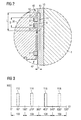
- a diagram is shown, wherein the ordinate 100 constitutes the portion in which the annular crevice 18 is in fluid communication with the lower piston section 42 via the venting grooves 14, 16, and the abscissa 101 constitutes the crank angle over a complete four-stroke cycle including an intake stroke 102, a compression stroke 104, a power stroke 106, and an exhaust stroke 108, wherein a crank angle of 0° indicates the begin of the intake stroke and a crank angle of 720° indicates the end of the exhaust stroke and, thus, the end of the complete four-stroke cycle.
- the four-stroke cycle is in the intake stroke 102.
- the four-stroke cycle is in the compression stroke 104.
- the four-stroke cycle is in the power stroke 106.
- the four-stroke cycle is in the exhaust stroke 108.
- the piston 30 is at the TDC, which means at the upper position indicated by the dotted lines in Fig. 1
- the piston 30 is at the BDC, which means at the lower position indicated by the dotted lines in Fig. 1 .
- the four-stroke cycle starts with the intake stroke 102.
- the piston 30 is in the TDC and begins to move downwardly.
- the intake valve 22 opens, such that, during the intake stroke 102, a predetermined amount of the air/fuel mixture is injected into the combustion chamber 28.
- the predetermined amount of the air/fuel-mixture may be provided under a predetermined intake pressure originating from, for example, a turbocharger unit of the internal combustion engine 1.
- the exhaust valve 26 is closed.
- the annular crevice 18 gets in fluid communication with the lower piston section 42, such that a small amount of the air/fuel-mixture may bypass the piston into the lower piston section 42.
- the leakage of air/fuel-mixture at this time is indicated by a first dotted line 112 in Fig. 3 .
- the air/fuel-mixture is allowed to bypass the piston into the lower piston section 42, as the length L of each of the plurality of venting grooves 14, 16 is greater than the piston ring thickness D.
- the piston 30 moves upwardly and the compression stroke 104 starts.
- the intake valve 22 closes such that the piston 30 compresses the air/fuel-mixture within the combustion chamber 28 while moving upwardly.
- the pressure of the air/fuel-mixture within the combustion chamber 28 may continuously increase, as the volume of the combustion chamber 28 continuously decreases during the upward movement of the piston 30.
- the pressure within the combustion chamber 28 may depend on the engine load. Thus, it may be desired that the combustion chamber pressure corresponds to the actual charge pressure.
- the upper edge 33 of the first piston ring 32 passes the upper edge 15 of the venting groove 14, such that the annular crevice 18 gets out of fluid communication with the lower piston section 42, thereby restricting the air/fuel-mixture to drain out of the upper piston section 40 into the lower piston section 42.
- At least some amount of the air/fuel-mixture may be urged into the annular crevice 18.
- the air/fuel-mixture trapped within the annular crevice 18 is restricted to flow further downwardly.
- a spark plug (not shown) may provide a spark igniting the air/fuel-mixture within the combustion chamber 28.
- the burning mixture may expand and, thus, may urge the piston 30 downwardly, which means that the power stroke 106 starts.
- the burning fuel may be at least partially quenched when contacting the piston, the air/fuel-mixture trapped within the annular crevice 18 may not be ignited and, thus, may maintain unburned. Further, the expanding burning fuel may additionally urge unburned air/fuel mixture into the annular crevice 18 and may further compress the same.
- the upper edge 33 of the first piston ring 32 passes the upper edge 15 of the venting groove 14, such that the annular crevice 18 gets again in fluid communication with the lower piston section 42. This is indicated by the solid line 116 of Fig. 3 .
- the pressure of the unburned air/fuel mixture at this time may be, for example, about 20 bar, the unburned air/fuel-mixture trapped within the annular crevice 18 flows out of the combustion chamber 28 into the plurality of venting grooves 14, 16 and into the lower piston section 42.
- the unburned air/fuel-mixture may downwardly flow into the lower piston portion until the crank angle reaches about 455°, which means a crank angle of 95° after the TDC during the power stroke 106. Then, the lower edge 35 of the second piston ring 34 passes the lower edge 17 of the venting groove 14, such that the fluid communication between the annular crevice 18 and the lower piston section 42 is interrupted.
- the annular crevice 18 is in fluid communication with the lower piston section 42, such that the unburned amount of air/fuel-mixture accumulated within the annular crevice 18 may be regained.
- the pressure of the exhaust gas during the exhaust stroke 108 may be much smaller than the pressure of the air/fuel-mixture during the power stroke 106, for example, at maximum about 5 bar
- the amount of exhaust gas flowing into the lower piston section 42 is much smaller than the amount of unburned air/fuel-mixture passing from the annular crevice 18 into the lower piston section 42.
- the amount of exhaust gas is negligible as compared to the amount of the regained unburned air/fuel-mixture.
- the upper edge 33 of the first piston ring 32 passes the upper edge 15 of the venting groove 14, such that the annular crevice 18 gets out of fluid communication with the lower piston section 42.
- crank angle range from about 635° to 720°, which means a crank angle range from about 275° to 360° after the TDC, the exhaust gas within the combustion chamber 28 is urged out of the same by the piston 30 moving upwardly.
- the piston 30 is again in the TDC. Then, the above described four-stroke cycle may start again beginning with the intake stroke 102.
- a re-supplying connection (not shown) may be configured to fluidly connect the crankcase to the inlet channel 20, such that the unburned air/fuel-mixture may be re-supplied in a subsequent combustion cycle.
- the piston 30 comprises only one piston ring sealingly contacting the cylinder 2
- the above detailed description may also be applied to such embodiments.
- the upper edge of the first piston ring 32 may correspond to the upper edge of the only one piston ring
- the lower edge of the second piston ring 34 may correspond to the lower edge of the only one piston ring.
- Each of the plurality of venting grooves 14, 16 may include a circular cross-section having a depth t in a range from, for example, about 0.2 mm to 1.0 mm, preferably about 0.5 mm.
- each of the plurality of venting grooves 14, 16 may comprise any other cross-section suitable to bypass at least the amount of unburned air/fuel-mixture of the annular crevice 18 into the lower-piston portion.
Landscapes
- Engineering & Computer Science (AREA)
- Mechanical Engineering (AREA)
- General Engineering & Computer Science (AREA)
- Chemical & Material Sciences (AREA)
- Combustion & Propulsion (AREA)
- Cylinder Crankcases Of Internal Combustion Engines (AREA)
- Pistons, Piston Rings, And Cylinders (AREA)
Abstract
Description
- The present disclosure generally relates to an internal combustion engine comprising at least one flow channel for venting unburned air/fuel-mixture out of a combustion chamber.
- During operation of internal combustion engines, exhaust gases may include quench gases from the combustion chamber surfaces and crevice volumes in the spaces between the piston and cylinder wall where unburned fuel, especially unburned air/fuel-mixture, is present after the end of combustion in the engine cylinders. Therefore, it is desired to gain the amount of unburned air/fuel-mixture and to recycle the same during a subsequent combustion cycle.
- For example,
US 4 191 150 A discloses an engine with selective venting of unburned mixture from the piston crevice volume. Particularly, venting means include one or more bypass channels in the cylinder wall which bypasses the piston rings and connects the crevice volume with the engine crankcase in the lower portions of the piston stroke. The mixture is removed during the latter portion of the power stroke. -
US 5 357 919 A discloses a hydrocarbon emission control for a four-stroke spark ignited internal combustion engine having a variable volume chamber and an auxiliary chamber with a fixed volume which is smaller than the maximum volume of the working chamber. The working chamber and the auxiliary chamber are connected to each other by a series of passages in the cylinder wall, wherein the passages in the cylinder wall are situated such that when the piston is near the top of its exhaust stroke, the end gases stored in the auxiliary chamber are discharged into the crankcase. -
US 6431 157 B1 discloses an internal combustion engine comprising a cylinder block with at least one cylinder barrel, a cylinder head with at least one inlet channel and exhaust channel with related inlet and exhaust valves to a combustion chamber situated above a piston moveable in the cylinder barrel and a crankcase for lubricating oil situated below the piston. The piston includes at least two grooves situated at a distance from each other, each having a piston ring and a piston collection chamber contained between the rings. - The present disclosure is directed, at least in part, to improving or overcoming one or more aspects of prior systems.
- According to an aspect of the present disclosure, an internal combustion engine may comprise a cylinder, a piston reciprocally movable within the cylinder between a top dead center and a bottom dead center, wherein the piston may separate the cylinder into an upper piston section and a lower piston section. The piston may include at least one piston ring configured to sealingly contact the cylinder and having a piston ring thickness. The internal combustion engine may further comprise an annular crevice being in fluid communication with the upper piston section and being defined by the cylinder, the piston and the at least one piston ring, and a plurality of venting grooves vertically disposed in the cylinder and each having a length being greater than the piston ring thickness. The plurality of venting grooves may be configured and positioned to fluidly connect the annular crevice with the lower piston section, when the piston has a position corresponding to a crank angle range of about 85° to 95° and about 265° to 275° after the top dead center.
- According to another aspect of the present disclosure, a method for operating an internal combustion engine including a cylinder defining a combustion chamber within, a piston reciprocally movable within the cylinder between a top dead center and a bottom dead center, and an inlet channel configured to supply a predetermined amount of an air/fuel-mixture into the combustion chamber may comprise directing unburned air/fuel-mixture out of an annular crevice formed between the cylinder and the piston and being in fluid communication with the combustion chamber into the intake channel, only when the piston has a position corresponding to a crank angle range of about 85° to 95° after the top dead center during a power stroke of the internal combustion engine.
- According to another aspect of the present disclosure, a cylinder liner configured to be inserted into a cylinder of an internal combustion engine may comprise a circumferential wall configured to reciprocally guide a piston between a top dead center and a bottom dead center. The piston may separate the cylinder liner into an upper piston section and a lower piston section, and may include at least one piston ring configured to sealingly contact the circumferential wall and having a piston ring thickness, such that an annular crevice may be defined by the circumferential wall, the piston, and the at least one piston ring. The disclosed cylinder liner may further comprise a plurality of venting grooves vertically disposed in the circumferential wall. Each of the plurality of venting grooves may have a length being greater than the piston ring thickness, wherein the plurality of venting grooves may be configured and positioned to fluidly connect the annular crevice to the lower piston section, only when the piston has a position corresponding to a crank angle range of about 85° to 95° and 265° to 275° after the top dead center.
- In some embodiments, the length of each of the plurality of venting grooves may be at maximum about 50 % greater than the piston ring thickness.
- In some embodiments, the internal combustion engine may further comprise a cylinder liner inserted into the cylinder, such that the piston is reciprocally disposed within the cylinder liner and the annular crevice is defined by the cylinder liner, the piston and the at least one piston ring, wherein the plurality of venting grooves is vertically disposed in the cylinder liner.
- In some embodiments, the piston may comprise a plurality of piston rings configured to sealingly contact the cylinder. In such embodiments, the piston ring thickness may be defined by the distance between an upper edge of the uppermost piston ring and a lower edge of the lowermost piston ring.
- Other features and aspects of this disclosure will be apparent from the following description and the accompanying drawings.
-
-
Fig. 1 shows a schematic view of an exemplary disclosed internal combustion engine; -
Fig. 2 shows a schematic view of an detail II - II of the internal combustion engine ofFig. 1 ; and -
Fig. 3 is a graphical illustration associating the leakage area between the upper portion and lower portion of the piston in dependency of the crank angle during a four-stroke cycle. - The following is a detailed description of exemplary embodiments of the present disclosure. The exemplary embodiments described therein and illustrated in the drawings are intended to teach the principles of the present disclosure, enabling those of ordinary skill in the art to implement and use the present disclosure in many different environments and for many different applications. Therefore, the exemplary embodiments are not intended to be, and should not be considered as, a limiting description of the scope of patent protection. Rather, the scope of patent protection shall be defined by the appended claims.
- The present disclosure may be based in part on the realization that providing a cylinder of an internal combustion with a plurality of vertical venting grooves situated such that each of the plurality of venting grooves fluidly connects an annular crevice trapping unburned air/fuel-mixture at a piston reciprocally disposed within the cylinder with a portion below the piston, when the piston has a position corresponding to a crank angle range of about 85° to 95° after the top dead center during a power stroke of the internal combustion engine, may release unburned fuel from the annular crevice and, thus, may prevent exhausting the unburned air/fuel-mixture. Furthermore, this may increase the efficiency of the internal combustion engine.
- The present disclosure may be further based in part on the realization that the internal combustion engine may also be provided with a cylinder liner being inserted into the cylinder. In such case, the cylinder liner includes the plurality of vertical venting grooves of which each is configured to fluidly connect the annular crevice with the lower piston portion. Also in such case, the unburned air/fuel-mixture trapped in the annular crevice formed by the cylinder liner and the piston reciprocally disposed within the cylinder liner may be released out of the combustion chamber and may be re-supplied for combusting in a subsequent combustion cycle.
- Referring now to the drawings, a
cylinder liner 10 inserted into acylinder 2 of anengine block 4 of aninternal combustion engine 1 is illustrated inFig. 1 . However, as already mentioned above, the present disclosure may be also applicable to internal combustion engines that may not comprise a cylinder liner. - The
internal combustion engine 1 may include features not shown, such as fuel systems, air systems, cooling systems, peripheries, drive train components, etc. For the purposes of the present disclosure, theinternal combustion engine 1 is considered as a four-stroke gaseous fuel internal combustion engine. One skilled in the art will recognize, however, that theinternal combustion engine 1 may be any type of engine (gas, diesel, natural gas, propane, dual fuel, etc.) that would utilize ventilation of unburned air/fuel mixture out of the crevice volume from the combustion chamber. Furthermore, the gaseous fuelinternal combustion engine 1 may be of any size, with any number of cylinders, and in any configuration ("V," in-line, radial, etc.). - The
internal combustion engine 1 may be used to power any machine or other device, including locomotive applications, on-highway trucks or vehicles, off-highway trucks or machines, earth moving equipment, generators, aerospace applications, marine applications, pumps, stationary equipment, or other engine powered applications. - The
cylinder liner 10 including acircumferential wall 12 defining acombustion chamber 28 therein is sealingly inserted into thecylinder 2. Particularly, sealing rings (not explicitly shown in the drawings) may be configured to seal between thecylinder liner 10 and thecylinder 2. - As shown in
Fig.1 , acylinder head 6 is configured to close an upper end of thecylinder 2 and thecylinder liner 10. Thecylinder head 6 is provided with aninlet channel 20 and anoutlet channel 24 being provided with anintake valve 22 and anexhaust valve 26, respectively. Theintake valve 22 is configured to open and close theinlet channel 20, thereby enabling or restricting air/fuel-mixture to enter thecombustion chamber 28. Theexhaust valve 26 is configured to open and close theoutlet channel 24, thereby enabling or restricting exhaust gas to leave thecombustion chamber 28. An engine control unit (not explicitly illustrated in the drawings) may be configured to control theintake valve 22 and theexhaust valve 26, respectively. - A
piston 30 is reciprocally disposed within thecylinder liner 10 along an axis C and is movable between a top dead center (in the following referred to as TDC) and a bottom dead center (in the following referred to as BDC). Specifically, thepiston 30 separates the volume of thecylinder liner 10 into anupper piston section 40 defining thecombustion chamber 28, and alower piston section 42 positioned below thepiston 30. Thepiston 30 is configured to vary the volume of thecombustion chamber 28 by reciprocally moving between the TDC and the BDC. Thepiston 30 is further indicated as being positioned in the TDC, which means near theintake valve 22 and theexhaust valve 26, and the BDC, which means the point farthest away from theintake valve 22 andexhaust valve 26. Both positions of thepiston 30 the TDC and the BDC are indicated by dotted lines inFig. 1 . - As shown in
Fig.1 , thepiston 30 includes a top end 31 facing thecombustion chamber 28. Thepiston 30 is provided with afirst piston ring 32 and asecond piston ring 34 disposed below thefirst piston ring 32. Thefirst piston ring 32 and thesecond piston ring 34 are both configured to seal thecombustion chamber 28 against thelower piston section 42, which includes sealing against the crankcase. Thepiston 30 further includes at least onescraping piston ring 37 configured to wipe over the inner wall of the cylinder, thereby wiping lubricating oil. As thescraping piston ring 37 is not a sealing piston ring as the first and second piston rings 32, 34, gaseous fluids, such as, for example, unburned air/fuel-mixture and exhaust gas, may be enabled to freely pass thescraping piston ring 37. - In some embodiments, the
piston 30 may be provided with only one piston ring, such as, for example, only thefirst piston ring 32. In such case, the only one piston ring is configured to sealingly contact thecylinder 2 and, therefore, to seal theupper piston section 40 against, for example, the crankcase. - The
cylinder liner 10 includes a plurality of ventinggrooves circumferential wall 12. RegardingFig. 1 , two ventinggrooves cylinder liner 10 may comprise less or more than two ventinggrooves cylinder liner 10 may comprise six venting grooves symmetrically disposed about the circumference of thecylinder liner 10. The plurality of ventinggrooves combustion chamber 28 and to direct the unburned air/fuel-mixture into thelower piston section 42. - Regarding
Fig. 2 , an enlarged view of the ventinggroove 14 is shown. As illustrated, anannular crevice 18 is formed at thepiston 30. Particularly, theannular crevice 18 is defined by thecylinder liner 10, the circumference of thepiston 30, thefirst piston ring 32 and an imaginary elongation of the top end 31 of thepiston 30. In some embodiments, which do not utilize acylinder liner 10, theannular crevice 18 may be defined by an inner wall of thecylinder 2, the circumference of thepiston 30, thefirst piston ring 32 and an imaginary elongation of the top end 31 of thepiston 30. - A
piston rod 36 is connected to thepiston 30 by a piston pin 38 being axially secured by two locking rings 39. Thepiston rod 36 is configured to be connected to a crankshaft (not shown in the drawings) disposed within a crankcase (not shown) of theengine block 4, such that rotation of the crankshaft results in a reciprocating motion of thepiston 30 within thecylinder liner 10. The person skilled in the art will recognize that, at a crank angle of 0°, thepiston 30 may be positioned at the TDC, and at a crank angle of 180°, thepiston 30 may be positioned at the BDC. - The
first piston ring 32 and thesecond piston ring 34 are spaced apart from each other by a piston ring thickness D. Particularly, the piston ring thickness D may be defined by anupper edge 33 of thefirst piston ring 32 and alower edge 35 of thesecond piston ring 34. - In some embodiments, where only one sealing piston ring is provided, the piston ring thickness D may be defined by the thickness of the only one sealing piston ring, in particular, by the upper edge and the lower edge of the only one sealing piston ring.
- The venting
groove 14 may comprise a length L in the vertical direction parallel to the axis C and a depth t extending perpendicular to the axis C. The length L of each of the ventinggrooves upper piston section 40 is fluidly connected to thelower piston section 42 during limited portions of the four-stroke cycle, which will be described in more detail below. - As shown in
Fig. 2 , the ventinggroove 14 may comprise a rectangular shape in the illustrated view, such that anupper edge 15 of the ventinggroove 14 extends perpendicular with respect to the axis C. However, in some embodiment, theupper edge 15 may also be provided in a sloped shape, such that the cross-section in a downward direction is continuously enhanced until the depth t of the ventinggroove 14 is reached. Similarly, the ventinggroove 14 may further include alower edge 17 that may also extend perpendicular with respect to the axis C. In some embodiments, similarly to theupper edge 15, thelower edge 17 may also comprise a sloped shape. - The plurality of venting
grooves annular crevice 18 with thelower piston section 42, when thepiston 30 is situated such that the crank angle is in a range from about 85° to 95° after the TDC, particularly during the power stroke of theinternal combustion engine 1, which will be described in more detail below. The downward flow of the unburned air/fuel-mixture bypassing thepiston 30 is indicated inFig. 2 by an arrow A. - After venting the unburned air/fuel-mixture from the
annular crevice 18 out of thecombustion chamber 28 into thelower piston section 42, the unburned air/fuel-mixture may be re-supplied to theinlet channel 20 and, thus, to thecombustion chamber 28 during a subsequent combustion cycle. Therefore, the vented unburned air/fuel-mixture may be firstly directed into the crankcase, where the unburned air/fuel-mixture may be accumulated. Subsequently, the accumulated air/fuel-mixture within the crankcase may then be re-supplied to thecombustion chamber 28 via theinlet channel 20. - It is noted that the
internal combustion engine 1 may be provided without acylinder liner 10. In such case, the plurality of ventinggrooves cylinder 2, such that theannular crevice 18 is fluidly connected to thelower piston section 42, when thepiston 30 is in the same position as mentioned above, namely when the crank angle is in a range from about 85° to 95°. - In the following, operation of the
internal combustion engine 1 is described with reference toFigs. 1 to 3 . - Referring to
Fig. 3 , a diagram is shown, wherein theordinate 100 constitutes the portion in which theannular crevice 18 is in fluid communication with thelower piston section 42 via the ventinggrooves abscissa 101 constitutes the crank angle over a complete four-stroke cycle including anintake stroke 102, acompression stroke 104, apower stroke 106, and anexhaust stroke 108, wherein a crank angle of 0° indicates the begin of the intake stroke and a crank angle of 720° indicates the end of the exhaust stroke and, thus, the end of the complete four-stroke cycle. - Specifically, during a crank angle range from 0° to 180°, the four-stroke cycle is in the
intake stroke 102. During a crank angle range from 180° to 360°, the four-stroke cycle is in thecompression stroke 104. During a crank angle range from 360° to 540°, the four-stroke cycle is in thepower stroke 106. During a crank angle range from 540° to 720°, the four-stroke cycle is in theexhaust stroke 108. - Furthermore, at crank angles of 0°, 360° and 720°, the
piston 30 is at the TDC, which means at the upper position indicated by the dotted lines inFig. 1 , whereas at crank angles of 180° and 540°, thepiston 30 is at the BDC, which means at the lower position indicated by the dotted lines inFig. 1 . - As already mentioned above, at a crank angle of 0°, the four-stroke cycle starts with the
intake stroke 102. At this time, thepiston 30 is in the TDC and begins to move downwardly. Then, theintake valve 22 opens, such that, during theintake stroke 102, a predetermined amount of the air/fuel mixture is injected into thecombustion chamber 28. The predetermined amount of the air/fuel-mixture may be provided under a predetermined intake pressure originating from, for example, a turbocharger unit of theinternal combustion engine 1. At this time, theexhaust valve 26 is closed. - When the crank angle reaches about 85°, which means 85° after the TDC during the
intake stroke 102, theannular crevice 18 gets in fluid communication with thelower piston section 42, such that a small amount of the air/fuel-mixture may bypass the piston into thelower piston section 42. The leakage of air/fuel-mixture at this time is indicated by a firstdotted line 112 inFig. 3 . Specifically, when theupper edge 33 of the first piston ring passes theupper edge 15 of the ventinggroove 14, the air/fuel-mixture is allowed to bypass the piston into thelower piston section 42, as the length L of each of the plurality of ventinggrooves - Then, when the crank angle reaches about 95°, which means 95° after the TDC during the
intake stroke 102, thelower edge 35 of thesecond piston ring 34 passes thelower edge 17 of the ventinggroove 14, such that the air/fuel-mixture is restricted from bypassing thepiston 30. - After passing the BDC at a crank angle of 180°, the
piston 30 moves upwardly and thecompression stroke 104 starts. Thus, at least at that time, theintake valve 22 closes such that thepiston 30 compresses the air/fuel-mixture within thecombustion chamber 28 while moving upwardly. During thecompression stroke 104, the pressure of the air/fuel-mixture within thecombustion chamber 28 may continuously increase, as the volume of thecombustion chamber 28 continuously decreases during the upward movement of thepiston 30. The pressure within thecombustion chamber 28 may depend on the engine load. Thus, it may be desired that the combustion chamber pressure corresponds to the actual charge pressure. - When reaching a crank angle of 265°, which means a crank angle of 265° after the TDC, the
lower edge 35 of thesecond piston ring 34 passes thelower edge 17 of the ventinggroove 14, such that theupper piston section 40, particularly theannular crevice 18, gets again in fluid communication with thelower piston section 42. This is indicated by a seconddotted line 114 inFig. 3 . - At that time, a small amount of compressed air/fuel-mixture may flow out of the
upper piston section 40 into thelower piston section 42 via the plurality of ventinggrooves upper piston section 40 is higher than the pressure within thelower piston section 42, due to the compression of the air/fuel-mixture. Therefore, this amount of air/fuel-mixture leakage may be considered during injection of the air/fuel-mixture during theintake stroke 102. Namely, an increased amount of the air/fuel-mixture may be injected. However, the added injected air/fuel-mixture amount may be regained as described below. - When reaching a crank angle of about 275°, which means a crank angle of about 275° after the TDC, the
upper edge 33 of thefirst piston ring 32 passes theupper edge 15 of the ventinggroove 14, such that theannular crevice 18 gets out of fluid communication with thelower piston section 42, thereby restricting the air/fuel-mixture to drain out of theupper piston section 40 into thelower piston section 42. - During the
compression stroke 104, especially during a crank angle range of about 275° to 360°, which means a crank angle range of about 275° to 360° after the TDC, at least some amount of the air/fuel-mixture may be urged into theannular crevice 18. As thefirst piston ring 32 sealingly contacts thecylinder liner 10, the air/fuel-mixture trapped within theannular crevice 18 is restricted to flow further downwardly. - When reaching a crank angle of 360°, the
piston 30 is in the TDC and the ignition may start. A spark plug (not shown) may provide a spark igniting the air/fuel-mixture within thecombustion chamber 28. The burning mixture may expand and, thus, may urge thepiston 30 downwardly, which means that thepower stroke 106 starts. - However, as the burning fuel may be at least partially quenched when contacting the piston, the air/fuel-mixture trapped within the
annular crevice 18 may not be ignited and, thus, may maintain unburned. Further, the expanding burning fuel may additionally urge unburned air/fuel mixture into theannular crevice 18 and may further compress the same. - When reaching a crank angle of about 445°, which means a crank angle of about 85° after the TDC during the
power stroke 106, theupper edge 33 of thefirst piston ring 32 passes theupper edge 15 of the ventinggroove 14, such that theannular crevice 18 gets again in fluid communication with thelower piston section 42. This is indicated by thesolid line 116 ofFig. 3 . As the pressure of the unburned air/fuel mixture at this time may be, for example, about 20 bar, the unburned air/fuel-mixture trapped within theannular crevice 18 flows out of thecombustion chamber 28 into the plurality of ventinggrooves lower piston section 42. - The unburned air/fuel-mixture may downwardly flow into the lower piston portion until the crank angle reaches about 455°, which means a crank angle of 95° after the TDC during the
power stroke 106. Then, thelower edge 35 of thesecond piston ring 34 passes thelower edge 17 of the ventinggroove 14, such that the fluid communication between theannular crevice 18 and thelower piston section 42 is interrupted. - Therefore, when the crank angle is in a range from about 445° to 455°, which means in a range from about 85° to 95° after the TDC during the
power stroke 106, theannular crevice 18 is in fluid communication with thelower piston section 42, such that the unburned amount of air/fuel-mixture accumulated within theannular crevice 18 may be regained. - Subsequently, when reaching a crank angle of 540°, which means that the
piston 30 is in the BDC, theexhaust stroke 108 starts and thepiston 30 begins to move upwardly again. At this time, theexhaust valve 26 opens and thepiston 30 urges the exhaust gas out of thecombustion chamber 28 through theoutlet channel 24. - During a crank angle range from about 625° to 635°, which means a crank angle range from about 265° to 275° after the TDC, the
lower edge 35 of thesecond piston ring 34 passes thelower edge 17 of the ventinggroove 14, such that theannular crevice 18 is again in fluid communication with thelower piston section 42, which is indicated by a thirddotted line 118 inFig. 3 . Thus, a small amount of exhaust gas may flow downwardly into thelower piston section 42. However, as the pressure of the exhaust gas during theexhaust stroke 108 may be much smaller than the pressure of the air/fuel-mixture during thepower stroke 106, for example, at maximum about 5 bar, the amount of exhaust gas flowing into thelower piston section 42 is much smaller than the amount of unburned air/fuel-mixture passing from theannular crevice 18 into thelower piston section 42. Particularly, the amount of exhaust gas is negligible as compared to the amount of the regained unburned air/fuel-mixture. - After passing a crank angle of about 635°, which means after passing a crank angle of about 275° after the TDC, the
upper edge 33 of thefirst piston ring 32 passes theupper edge 15 of the ventinggroove 14, such that theannular crevice 18 gets out of fluid communication with thelower piston section 42. - During a crank angle range from about 635° to 720°, which means a crank angle range from about 275° to 360° after the TDC, the exhaust gas within the
combustion chamber 28 is urged out of the same by thepiston 30 moving upwardly. - At the end of the
exhaust stroke 108, which also defines the end of the four-stroke cycle, thepiston 30 is again in the TDC. Then, the above described four-stroke cycle may start again beginning with theintake stroke 102. - When unburned air/fuel-mixture and/or exhaust gas flows into the crankcase, a re-supplying connection (not shown) may be configured to fluidly connect the crankcase to the
inlet channel 20, such that the unburned air/fuel-mixture may be re-supplied in a subsequent combustion cycle. - In some embodiments, where the
piston 30 comprises only one piston ring sealingly contacting thecylinder 2, the above detailed description may also be applied to such embodiments. Particularly, in such case, the upper edge of thefirst piston ring 32 may correspond to the upper edge of the only one piston ring, whereas the lower edge of thesecond piston ring 34 may correspond to the lower edge of the only one piston ring. - Each of the plurality of venting
grooves grooves annular crevice 18 into the lower-piston portion. - Although the preferred embodiments of this invention have been described herein, improvements and modifications may be incorporated without departing from the scope of the following claims.
Claims (15)
- An internal combustion engine (1) comprising:a cylinder (2);a piston (30) reciprocally movable within the cylinder (2) between a top dead center (TDC) and a bottom dead center (BDC), the piston (30) separating the cylinder (2) into an upper piston section (40) and a lower piston section (42), the piston (30) including at least one piston ring (32, 34) configured to sealingly contact the cylinder (2) and having a piston ring thickness (D);an annular crevice (18) being in fluid communication with the upper piston section (40) and being defined by the cylinder (2), the piston (30), and the at least one piston ring (32, 34); anda plurality of venting grooves (14, 16) vertically disposed in the cylinder (2) and each having a length (L) being greater than the piston ring thickness (D), the plurality of venting grooves (14, 16) being configured and positioned to fluidly connect the annular crevice (18) with the lower piston section (42), only when the piston (30) has a position corresponding to a crank angle range of about 85° to 95° and about 265° to 275° after the top dead center (TDC).
- The internal combustion engine (1) of claim 1, wherein the length (L) of each of the plurality of venting grooves (14, 16) is at maximum about 50 % greater than the piston ring thickness (D).
- The internal combustion engine (1) of any one of claim 1 or claim 2, further comprising a cylinder liner (10) inserted into the cylinder (2), such that the piston (30) is reciprocally disposed within the cylinder liner (10) and the annular crevice (18) is defined by the cylinder liner (10), the piston (30), and the at least one piston ring (32, 34), wherein the plurality of venting grooves (14, 16) is disposed in the cylinder liner (10).
- The internal combustion engine (1) of claim 3, wherein the cylinder liner (10) includes six venting grooves (14, 16) symmetrically disposed about the circumference of the cylinder liner (10).
- The internal combustion engine (1) of claim 3 or claim 4, wherein each of the plurality of venting grooves (14, 16) include an upper edge (15) being sloped.
- The internal combustion engine (1) of any one of claim 3 to 5, wherein each of the plurality of venting grooves (14, 16) include a lower edge (17) being sloped.
- The internal combustion engine (1) of any one of the preceding claims, wherein the piston ring thickness (D) is defined by a distance between an upper edge (33) of the at least one piston ring (32, 34) and a lower edge (35) of the at least one piston ring (32, 34).
- The internal combustion engine (1) of any one of the preceding claims, further comprising an inlet channel (20) fluidly connected to the upper piston section (40) and configured to supply an air/fuel-mixture into the upper piston section (40), wherein the lower piston section (42) is configured to be fluidly connected to the inlet channel (20), such that the vented unburned air/fuel mixture is re-supplied to the upper piston section (40) during a subsequent cycle.
- The internal combustion engine (1) of claim 8, further comprising a crankcase configured to include a crankshaft supporting the piston (30), wherein the crankcase is configured to be fluidly interconnected between the lower piston section (42) and the inlet channel (20).
- The internal combustion engine (1) of claim 9, further comprising a re-supplying channel configured to be fluidly interconnected between the crankcase and the inlet channel (20).
- The internal combustion engine (1) of any one of the preceding claims, wherein the upper piston section (40) defines a combustion chamber (28) configured to combust an air/fuel-mixture within.
- A method for operating an internal combustion engine (1) including a cylinder (2) defining a combustion chamber (28) within, a piston (30) reciprocally movable within the cylinder (2) between a top dead center (TDC) and a bottom dead center (BDC), and an inlet channel (20) configured to supply a predetermined amount of an air/fuel-mixture into the combustion chamber (28), the method comprising:directing unburned air/fuel-mixture out of an annular crevice (18) formed between the cylinder (2) and the piston (30) and being in fluid communication with the combustion chamber (28) into the intake channel (20), only when the piston (30) has a position corresponding to a crank angle range of about 85° to 95° after the top dead center (TDC) during a power stroke (116) of the internal combustion engine (1).
- The method of claim 12, further comprising directing the unburned air/fuel-mixture into a lower piston section (40) disposed below the piston (30) before directing the unburned air/fuel-mixture into the intake channel (20).
- The method of claim 13, wherein directing the unburned air/fuel-mixture into the lower piston section (40) includes bypassing the piston (30) via a plurality of venting grooves (14, 16).
- A cylinder liner (10) configured to be inserted into a cylinder (2) of an internal combustion engine (1), the cylinder liner (10) comprising:a circumferential wall (12) configured to reciprocally guide a piston (30) between a top dead center (TDC) and a bottom dead center (BDC), the piston (30) separating the cylinder liner (10) into an upper piston section (40) and a lower piston section (42), and including at least one piston ring (32, 34) configured to sealingly contact the circumferential wall (12) and having a piston ring thickness (D), such that an annular crevice (18) is defined by the circumferential wall (12), the piston (30), and the at least one piston ring (32, 34); anda plurality of venting grooves (14, 16) vertically disposed in the circumferential wall (12) and each of the plurality of venting grooves (14, 16) having a length (L) being greater than the piston ring thickness (D), the plurality of venting grooves (14, 16) being configured and positioned to fluidly connect the annular crevice (18) to the lower piston section (42), only when the piston (30) has a position corresponding to a crank angle range of about 85° to 95° and about 265° to 275° after the top dead center (TDC).
Priority Applications (4)
| Application Number | Priority Date | Filing Date | Title |
|---|---|---|---|
| EP12198864.6A EP2746531B1 (en) | 2012-12-21 | 2012-12-21 | Unburned fuel venting in internal combustion engines |
| PCT/EP2013/003928 WO2014095087A1 (en) | 2012-12-21 | 2013-12-20 | Unburned fuel venting in internal combustion engines |
| US14/652,766 US20150337774A1 (en) | 2012-12-21 | 2013-12-20 | Unburned fuel venting in internal combustion engines |
| CN201380065599.0A CN104870749A (en) | 2012-12-21 | 2013-12-20 | Unburned fuel venting in internal combustion engines |
Applications Claiming Priority (1)
| Application Number | Priority Date | Filing Date | Title |
|---|---|---|---|
| EP12198864.6A EP2746531B1 (en) | 2012-12-21 | 2012-12-21 | Unburned fuel venting in internal combustion engines |
Publications (2)
| Publication Number | Publication Date |
|---|---|
| EP2746531A1 true EP2746531A1 (en) | 2014-06-25 |
| EP2746531B1 EP2746531B1 (en) | 2015-07-22 |
Family
ID=47678505
Family Applications (1)
| Application Number | Title | Priority Date | Filing Date |
|---|---|---|---|
| EP12198864.6A Not-in-force EP2746531B1 (en) | 2012-12-21 | 2012-12-21 | Unburned fuel venting in internal combustion engines |
Country Status (4)
| Country | Link |
|---|---|
| US (1) | US20150337774A1 (en) |
| EP (1) | EP2746531B1 (en) |
| CN (1) | CN104870749A (en) |
| WO (1) | WO2014095087A1 (en) |
Cited By (1)
| Publication number | Priority date | Publication date | Assignee | Title |
|---|---|---|---|---|
| US9194327B2 (en) | 2014-04-07 | 2015-11-24 | General Electric Company | Cylinder liner with slots |
Families Citing this family (3)
| Publication number | Priority date | Publication date | Assignee | Title |
|---|---|---|---|---|
| US9856821B1 (en) * | 2016-10-14 | 2018-01-02 | Etagen, Inc. | Open-faced piston assembly |
| CN111188692A (en) * | 2018-11-15 | 2020-05-22 | 日立汽车系统(苏州)有限公司 | Device to improve oil dilution |
| DE102020112480A1 (en) | 2020-05-08 | 2021-11-11 | Man Energy Solutions Se | Cylinder liner and cylinder of an internal combustion engine |
Citations (8)
| Publication number | Priority date | Publication date | Assignee | Title |
|---|---|---|---|---|
| US4191150A (en) | 1978-03-20 | 1980-03-04 | General Motors Corporation | Engine with selective venting of unburned mixture from the piston crevice volume |
| US4363310A (en) * | 1980-07-03 | 1982-12-14 | General Motors Corporation | Diesel engine with blowby scavenging |
| JPS6226346A (en) * | 1985-07-25 | 1987-02-04 | Mitsubishi Heavy Ind Ltd | Cylinder liner having comrpessed-gas blowing-out passage |
| US5357919A (en) | 1991-01-19 | 1994-10-25 | Ford Motor Company | Hydrocarbon emission control |
| WO1997042406A1 (en) * | 1996-05-07 | 1997-11-13 | Man B & W Diesel A/S | A cylinder liner for an internal combustion engine |
| US6431157B1 (en) | 1999-06-07 | 2002-08-13 | Volvo Car Corporation | Internal combustion engine |
| JP2005105934A (en) * | 2003-09-30 | 2005-04-21 | Mazda Motor Corp | Engine blowback suppression structure and manufacturing method thereof |
| US20090126672A1 (en) * | 2007-11-17 | 2009-05-21 | Predag Ostojic | Handheld work apparatus |
Family Cites Families (18)
| Publication number | Priority date | Publication date | Assignee | Title |
|---|---|---|---|---|
| US1540602A (en) * | 1924-05-03 | 1925-06-02 | Cornelius S Clark | Internal-combustion engine |
| US1814781A (en) * | 1927-05-04 | 1931-07-14 | Ass Elect Ind | Internal combustion engine |
| US1874446A (en) * | 1931-03-26 | 1932-08-30 | Wright Aero Nautical Corp | Ported cylinder construction |
| US2068514A (en) * | 1933-04-06 | 1937-01-19 | Busch Sulzer Bros Diesel Engine Co | Engine sludge chamber |
| US2971802A (en) * | 1958-10-02 | 1961-02-14 | Caterpillar Tractor Co | Grooved cylinder liner for reduced ring groove wear |
| US3160149A (en) * | 1961-04-20 | 1964-12-08 | Stevens Inst Technology | Cylinder for a high performance internal combustion engine |
| US3905340A (en) * | 1972-08-22 | 1975-09-16 | Performance Industries | Engine valving and porting |
| JPS5840649B2 (en) * | 1972-08-22 | 1983-09-07 | パ−フオ−マンス インダストリイズ インコ−ポレ−テツド | benzouchi |
| US4202299A (en) * | 1972-08-22 | 1980-05-13 | Performance Industries, Inc. | Two cycle internal combustion engine |
| US4370959A (en) * | 1980-05-30 | 1983-02-01 | Avco Corporation | Two stroke cycle engine with sustained power stroke |
| US7082910B2 (en) * | 1999-01-19 | 2006-08-01 | Aktiebolaget Electrolux | Two-stroke internal combustion engine |
| US6591793B2 (en) * | 1999-11-12 | 2003-07-15 | Maruyama Mfg. Co., Inc. | Two-cycle engine |
| WO2005003527A2 (en) * | 2003-07-08 | 2005-01-13 | Avl List Gmbh | Internal combustion engine |
| US20130213341A1 (en) * | 2012-02-16 | 2013-08-22 | Teoman Uzkan | Engine having piston with l-shaped timing ring |
| US20140000549A1 (en) * | 2012-06-29 | 2014-01-02 | Frank Matthew Graczyk | Compression ring for an engine |
| EP2746553B1 (en) * | 2012-12-21 | 2016-04-20 | Caterpillar Energy Solutions GmbH | Unburned fuel venting in internal combustion engines |
| CN203948172U (en) * | 2013-04-04 | 2014-11-19 | 艾克莫特公司 | Opposed piston type engine |
| US9938926B2 (en) * | 2014-10-07 | 2018-04-10 | Yamabiko Corporation | Air leading-type stratified scavenging two-stroke internal-combustion engine |
-
2012
- 2012-12-21 EP EP12198864.6A patent/EP2746531B1/en not_active Not-in-force
-
2013
- 2013-12-20 WO PCT/EP2013/003928 patent/WO2014095087A1/en not_active Ceased
- 2013-12-20 US US14/652,766 patent/US20150337774A1/en not_active Abandoned
- 2013-12-20 CN CN201380065599.0A patent/CN104870749A/en active Pending
Patent Citations (8)
| Publication number | Priority date | Publication date | Assignee | Title |
|---|---|---|---|---|
| US4191150A (en) | 1978-03-20 | 1980-03-04 | General Motors Corporation | Engine with selective venting of unburned mixture from the piston crevice volume |
| US4363310A (en) * | 1980-07-03 | 1982-12-14 | General Motors Corporation | Diesel engine with blowby scavenging |
| JPS6226346A (en) * | 1985-07-25 | 1987-02-04 | Mitsubishi Heavy Ind Ltd | Cylinder liner having comrpessed-gas blowing-out passage |
| US5357919A (en) | 1991-01-19 | 1994-10-25 | Ford Motor Company | Hydrocarbon emission control |
| WO1997042406A1 (en) * | 1996-05-07 | 1997-11-13 | Man B & W Diesel A/S | A cylinder liner for an internal combustion engine |
| US6431157B1 (en) | 1999-06-07 | 2002-08-13 | Volvo Car Corporation | Internal combustion engine |
| JP2005105934A (en) * | 2003-09-30 | 2005-04-21 | Mazda Motor Corp | Engine blowback suppression structure and manufacturing method thereof |
| US20090126672A1 (en) * | 2007-11-17 | 2009-05-21 | Predag Ostojic | Handheld work apparatus |
Cited By (1)
| Publication number | Priority date | Publication date | Assignee | Title |
|---|---|---|---|---|
| US9194327B2 (en) | 2014-04-07 | 2015-11-24 | General Electric Company | Cylinder liner with slots |
Also Published As
| Publication number | Publication date |
|---|---|
| CN104870749A (en) | 2015-08-26 |
| EP2746531B1 (en) | 2015-07-22 |
| WO2014095087A1 (en) | 2014-06-26 |
| US20150337774A1 (en) | 2015-11-26 |
Similar Documents
| Publication | Publication Date | Title |
|---|---|---|
| CN107429602B (en) | Internal combustion engine and method for operating an internal combustion engine | |
| EP2746553B1 (en) | Unburned fuel venting in internal combustion engines | |
| RU2011141891A (en) | HYBRID HYBRID ENGINE WITH A DIVIDED CYCLE AND METHOD FOR ITS OPERATION | |
| US9239003B1 (en) | Variable volume combustion chamber system | |
| EP2746531B1 (en) | Unburned fuel venting in internal combustion engines | |
| US9284916B2 (en) | Method for operating a reciprocating piston internal combustion engine with internal exhaust gas energy recuperation and reciprocating piston internal combustion engine | |
| GB2554719A (en) | System for evacuating residual gases from pre-chamber of engine | |
| US10578009B2 (en) | Two-stroke internal combustion engine | |
| US9964068B2 (en) | Head gasket for an internal combustion engine | |
| US11078836B1 (en) | System and method of reciprocating piston engine, multi-fuel piston engine | |
| RU2316658C1 (en) | Diesel engine | |
| JP2003307132A (en) | Two-stroke engine with stepped piston | |
| EP3371433B1 (en) | Four stroke internal combustion engine | |
| GB2425808A (en) | Supercharged two-stroke engine with separate direct injection of air and fuel | |
| US11674595B2 (en) | Scraper ring for a piston | |
| EP2088283A1 (en) | Reciprocating rotary internal combustion engine | |
| EP4513025A1 (en) | Internal combustion engine system | |
| KR101208053B1 (en) | Internal combustion engine with double piston head | |
| WO2015015508A2 (en) | Fixed piston, moving cylinder 2 stroke i c engine. with super charging annular chamber | |
| NL1042988B1 (en) | Novel two-stroke engine | |
| RU2375593C2 (en) | Method of maintaining combustion in internal combustion engine and cylinder head of above engine | |
| WO2021198551A1 (en) | A two-stroke engine | |
| JP2006348809A (en) | Internal combustion engine | |
| US20150059695A1 (en) | Long Power Stroke Engine | |
| WO2017078597A1 (en) | Four stroke internal combustion engine |
Legal Events
| Date | Code | Title | Description |
|---|---|---|---|
| PUAI | Public reference made under article 153(3) epc to a published international application that has entered the european phase |
Free format text: ORIGINAL CODE: 0009012 |
|
| 17P | Request for examination filed |
Effective date: 20121221 |
|
| AK | Designated contracting states |
Kind code of ref document: A1 Designated state(s): AL AT BE BG CH CY CZ DE DK EE ES FI FR GB GR HR HU IE IS IT LI LT LU LV MC MK MT NL NO PL PT RO RS SE SI SK SM TR |
|
| AX | Request for extension of the european patent |
Extension state: BA ME |
|
| RAP1 | Party data changed (applicant data changed or rights of an application transferred) |
Owner name: CATERPILLAR ENERGY SOLUTIONS GMBH |
|
| R17P | Request for examination filed (corrected) |
Effective date: 20141030 |
|
| RBV | Designated contracting states (corrected) |
Designated state(s): AL AT BE BG CH CY CZ DE DK EE ES FI FR GB GR HR HU IE IS IT LI LT LU LV MC MK MT NL NO PL PT RO RS SE SI SK SM TR |
|
| 17Q | First examination report despatched |
Effective date: 20141204 |
|
| GRAP | Despatch of communication of intention to grant a patent |
Free format text: ORIGINAL CODE: EPIDOSNIGR1 |
|
| INTG | Intention to grant announced |
Effective date: 20150227 |
|
| GRAS | Grant fee paid |
Free format text: ORIGINAL CODE: EPIDOSNIGR3 |
|
| GRAA | (expected) grant |
Free format text: ORIGINAL CODE: 0009210 |
|
| AK | Designated contracting states |
Kind code of ref document: B1 Designated state(s): AL AT BE BG CH CY CZ DE DK EE ES FI FR GB GR HR HU IE IS IT LI LT LU LV MC MK MT NL NO PL PT RO RS SE SI SK SM TR |
|
| REG | Reference to a national code |
Ref country code: GB Ref legal event code: FG4D |
|
| REG | Reference to a national code |
Ref country code: CH Ref legal event code: EP |
|
| REG | Reference to a national code |
Ref country code: IE Ref legal event code: FG4D |
|
| REG | Reference to a national code |
Ref country code: AT Ref legal event code: REF Ref document number: 738054 Country of ref document: AT Kind code of ref document: T Effective date: 20150815 |
|
| REG | Reference to a national code |
Ref country code: DE Ref legal event code: R096 Ref document number: 602012008916 Country of ref document: DE |
|
| REG | Reference to a national code |
Ref country code: LT Ref legal event code: MG4D |
|
| REG | Reference to a national code |
Ref country code: NL Ref legal event code: MP Effective date: 20150722 |
|
| PG25 | Lapsed in a contracting state [announced via postgrant information from national office to epo] |
Ref country code: LT Free format text: LAPSE BECAUSE OF FAILURE TO SUBMIT A TRANSLATION OF THE DESCRIPTION OR TO PAY THE FEE WITHIN THE PRESCRIBED TIME-LIMIT Effective date: 20150722 Ref country code: LV Free format text: LAPSE BECAUSE OF FAILURE TO SUBMIT A TRANSLATION OF THE DESCRIPTION OR TO PAY THE FEE WITHIN THE PRESCRIBED TIME-LIMIT Effective date: 20150722 Ref country code: GR Free format text: LAPSE BECAUSE OF FAILURE TO SUBMIT A TRANSLATION OF THE DESCRIPTION OR TO PAY THE FEE WITHIN THE PRESCRIBED TIME-LIMIT Effective date: 20151023 Ref country code: NO Free format text: LAPSE BECAUSE OF FAILURE TO SUBMIT A TRANSLATION OF THE DESCRIPTION OR TO PAY THE FEE WITHIN THE PRESCRIBED TIME-LIMIT Effective date: 20151022 Ref country code: FI Free format text: LAPSE BECAUSE OF FAILURE TO SUBMIT A TRANSLATION OF THE DESCRIPTION OR TO PAY THE FEE WITHIN THE PRESCRIBED TIME-LIMIT Effective date: 20150722 |
|
| PG25 | Lapsed in a contracting state [announced via postgrant information from national office to epo] |
Ref country code: SE Free format text: LAPSE BECAUSE OF FAILURE TO SUBMIT A TRANSLATION OF THE DESCRIPTION OR TO PAY THE FEE WITHIN THE PRESCRIBED TIME-LIMIT Effective date: 20150722 Ref country code: RS Free format text: LAPSE BECAUSE OF FAILURE TO SUBMIT A TRANSLATION OF THE DESCRIPTION OR TO PAY THE FEE WITHIN THE PRESCRIBED TIME-LIMIT Effective date: 20150722 Ref country code: ES Free format text: LAPSE BECAUSE OF FAILURE TO SUBMIT A TRANSLATION OF THE DESCRIPTION OR TO PAY THE FEE WITHIN THE PRESCRIBED TIME-LIMIT Effective date: 20150722 Ref country code: HR Free format text: LAPSE BECAUSE OF FAILURE TO SUBMIT A TRANSLATION OF THE DESCRIPTION OR TO PAY THE FEE WITHIN THE PRESCRIBED TIME-LIMIT Effective date: 20150722 Ref country code: IS Free format text: LAPSE BECAUSE OF FAILURE TO SUBMIT A TRANSLATION OF THE DESCRIPTION OR TO PAY THE FEE WITHIN THE PRESCRIBED TIME-LIMIT Effective date: 20151122 Ref country code: PT Free format text: LAPSE BECAUSE OF FAILURE TO SUBMIT A TRANSLATION OF THE DESCRIPTION OR TO PAY THE FEE WITHIN THE PRESCRIBED TIME-LIMIT Effective date: 20151123 Ref country code: PL Free format text: LAPSE BECAUSE OF FAILURE TO SUBMIT A TRANSLATION OF THE DESCRIPTION OR TO PAY THE FEE WITHIN THE PRESCRIBED TIME-LIMIT Effective date: 20150722 |
|
| REG | Reference to a national code |
Ref country code: DE Ref legal event code: R097 Ref document number: 602012008916 Country of ref document: DE |
|
| PG25 | Lapsed in a contracting state [announced via postgrant information from national office to epo] |
Ref country code: CZ Free format text: LAPSE BECAUSE OF FAILURE TO SUBMIT A TRANSLATION OF THE DESCRIPTION OR TO PAY THE FEE WITHIN THE PRESCRIBED TIME-LIMIT Effective date: 20150722 Ref country code: EE Free format text: LAPSE BECAUSE OF FAILURE TO SUBMIT A TRANSLATION OF THE DESCRIPTION OR TO PAY THE FEE WITHIN THE PRESCRIBED TIME-LIMIT Effective date: 20150722 Ref country code: IT Free format text: LAPSE BECAUSE OF FAILURE TO SUBMIT A TRANSLATION OF THE DESCRIPTION OR TO PAY THE FEE WITHIN THE PRESCRIBED TIME-LIMIT Effective date: 20150722 Ref country code: SK Free format text: LAPSE BECAUSE OF FAILURE TO SUBMIT A TRANSLATION OF THE DESCRIPTION OR TO PAY THE FEE WITHIN THE PRESCRIBED TIME-LIMIT Effective date: 20150722 Ref country code: DK Free format text: LAPSE BECAUSE OF FAILURE TO SUBMIT A TRANSLATION OF THE DESCRIPTION OR TO PAY THE FEE WITHIN THE PRESCRIBED TIME-LIMIT Effective date: 20150722 |
|
| PGFP | Annual fee paid to national office [announced via postgrant information from national office to epo] |
Ref country code: DE Payment date: 20151230 Year of fee payment: 4 |
|
| PLBE | No opposition filed within time limit |
Free format text: ORIGINAL CODE: 0009261 |
|
| STAA | Information on the status of an ep patent application or granted ep patent |
Free format text: STATUS: NO OPPOSITION FILED WITHIN TIME LIMIT |
|
| PG25 | Lapsed in a contracting state [announced via postgrant information from national office to epo] |
Ref country code: BE Free format text: LAPSE BECAUSE OF NON-PAYMENT OF DUE FEES Effective date: 20151231 Ref country code: RO Free format text: LAPSE BECAUSE OF FAILURE TO SUBMIT A TRANSLATION OF THE DESCRIPTION OR TO PAY THE FEE WITHIN THE PRESCRIBED TIME-LIMIT Effective date: 20150722 |
|
| 26N | No opposition filed |
Effective date: 20160425 |
|
| PG25 | Lapsed in a contracting state [announced via postgrant information from national office to epo] |
Ref country code: MC Free format text: LAPSE BECAUSE OF FAILURE TO SUBMIT A TRANSLATION OF THE DESCRIPTION OR TO PAY THE FEE WITHIN THE PRESCRIBED TIME-LIMIT Effective date: 20150722 Ref country code: LU Free format text: LAPSE BECAUSE OF FAILURE TO SUBMIT A TRANSLATION OF THE DESCRIPTION OR TO PAY THE FEE WITHIN THE PRESCRIBED TIME-LIMIT Effective date: 20151221 |
|
| REG | Reference to a national code |
Ref country code: CH Ref legal event code: PL |
|
| PG25 | Lapsed in a contracting state [announced via postgrant information from national office to epo] |
Ref country code: SI Free format text: LAPSE BECAUSE OF FAILURE TO SUBMIT A TRANSLATION OF THE DESCRIPTION OR TO PAY THE FEE WITHIN THE PRESCRIBED TIME-LIMIT Effective date: 20150722 |
|
| REG | Reference to a national code |
Ref country code: IE Ref legal event code: MM4A |
|
| REG | Reference to a national code |
Ref country code: FR Ref legal event code: ST Effective date: 20160831 |
|
| PG25 | Lapsed in a contracting state [announced via postgrant information from national office to epo] |
Ref country code: IE Free format text: LAPSE BECAUSE OF NON-PAYMENT OF DUE FEES Effective date: 20151221 Ref country code: LI Free format text: LAPSE BECAUSE OF NON-PAYMENT OF DUE FEES Effective date: 20151231 Ref country code: CH Free format text: LAPSE BECAUSE OF NON-PAYMENT OF DUE FEES Effective date: 20151231 |
|
| PG25 | Lapsed in a contracting state [announced via postgrant information from national office to epo] |
Ref country code: FR Free format text: LAPSE BECAUSE OF NON-PAYMENT OF DUE FEES Effective date: 20151231 |
|
| PG25 | Lapsed in a contracting state [announced via postgrant information from national office to epo] |
Ref country code: BE Free format text: LAPSE BECAUSE OF FAILURE TO SUBMIT A TRANSLATION OF THE DESCRIPTION OR TO PAY THE FEE WITHIN THE PRESCRIBED TIME-LIMIT Effective date: 20150722 |
|
| PG25 | Lapsed in a contracting state [announced via postgrant information from national office to epo] |
Ref country code: SM Free format text: LAPSE BECAUSE OF FAILURE TO SUBMIT A TRANSLATION OF THE DESCRIPTION OR TO PAY THE FEE WITHIN THE PRESCRIBED TIME-LIMIT Effective date: 20150722 Ref country code: HU Free format text: LAPSE BECAUSE OF FAILURE TO SUBMIT A TRANSLATION OF THE DESCRIPTION OR TO PAY THE FEE WITHIN THE PRESCRIBED TIME-LIMIT; INVALID AB INITIO Effective date: 20121221 Ref country code: BG Free format text: LAPSE BECAUSE OF FAILURE TO SUBMIT A TRANSLATION OF THE DESCRIPTION OR TO PAY THE FEE WITHIN THE PRESCRIBED TIME-LIMIT Effective date: 20150722 |
|
| PG25 | Lapsed in a contracting state [announced via postgrant information from national office to epo] |
Ref country code: CY Free format text: LAPSE BECAUSE OF FAILURE TO SUBMIT A TRANSLATION OF THE DESCRIPTION OR TO PAY THE FEE WITHIN THE PRESCRIBED TIME-LIMIT Effective date: 20150722 Ref country code: NL Free format text: LAPSE BECAUSE OF FAILURE TO SUBMIT A TRANSLATION OF THE DESCRIPTION OR TO PAY THE FEE WITHIN THE PRESCRIBED TIME-LIMIT Effective date: 20150722 |
|
| REG | Reference to a national code |
Ref country code: DE Ref legal event code: R119 Ref document number: 602012008916 Country of ref document: DE |
|
| REG | Reference to a national code |
Ref country code: AT Ref legal event code: UEP Ref document number: 738054 Country of ref document: AT Kind code of ref document: T Effective date: 20150722 |
|
| GBPC | Gb: european patent ceased through non-payment of renewal fee |
Effective date: 20161221 |
|
| PG25 | Lapsed in a contracting state [announced via postgrant information from national office to epo] |
Ref country code: MT Free format text: LAPSE BECAUSE OF FAILURE TO SUBMIT A TRANSLATION OF THE DESCRIPTION OR TO PAY THE FEE WITHIN THE PRESCRIBED TIME-LIMIT Effective date: 20150722 |
|
| PG25 | Lapsed in a contracting state [announced via postgrant information from national office to epo] |
Ref country code: GB Free format text: LAPSE BECAUSE OF NON-PAYMENT OF DUE FEES Effective date: 20161221 Ref country code: DE Free format text: LAPSE BECAUSE OF NON-PAYMENT OF DUE FEES Effective date: 20170701 |
|
| PG25 | Lapsed in a contracting state [announced via postgrant information from national office to epo] |
Ref country code: MK Free format text: LAPSE BECAUSE OF FAILURE TO SUBMIT A TRANSLATION OF THE DESCRIPTION OR TO PAY THE FEE WITHIN THE PRESCRIBED TIME-LIMIT Effective date: 20150722 |
|
| PG25 | Lapsed in a contracting state [announced via postgrant information from national office to epo] |
Ref country code: AL Free format text: LAPSE BECAUSE OF FAILURE TO SUBMIT A TRANSLATION OF THE DESCRIPTION OR TO PAY THE FEE WITHIN THE PRESCRIBED TIME-LIMIT Effective date: 20150722 Ref country code: TR Free format text: LAPSE BECAUSE OF FAILURE TO SUBMIT A TRANSLATION OF THE DESCRIPTION OR TO PAY THE FEE WITHIN THE PRESCRIBED TIME-LIMIT Effective date: 20150722 |
|
| REG | Reference to a national code |
Ref country code: AT Ref legal event code: MM01 Ref document number: 738054 Country of ref document: AT Kind code of ref document: T Effective date: 20171221 |
|
| PG25 | Lapsed in a contracting state [announced via postgrant information from national office to epo] |
Ref country code: AT Free format text: LAPSE BECAUSE OF NON-PAYMENT OF DUE FEES Effective date: 20171221 |