EP2746113A1 - Rotation blocking system for a key interlock device and key interlock device comprising such rotation blocking system - Google Patents
Rotation blocking system for a key interlock device and key interlock device comprising such rotation blocking system Download PDFInfo
- Publication number
- EP2746113A1 EP2746113A1 EP12198337.3A EP12198337A EP2746113A1 EP 2746113 A1 EP2746113 A1 EP 2746113A1 EP 12198337 A EP12198337 A EP 12198337A EP 2746113 A1 EP2746113 A1 EP 2746113A1
- Authority
- EP
- European Patent Office
- Prior art keywords
- lever
- intended
- axis
- blocking position
- blocking
- Prior art date
- Legal status (The legal status is an assumption and is not a legal conclusion. Google has not performed a legal analysis and makes no representation as to the accuracy of the status listed.)
- Granted
Links
- 230000000903 blocking effect Effects 0.000 title claims abstract description 115
- 238000013459 approach Methods 0.000 claims description 3
- 238000001514 detection method Methods 0.000 description 2
- 238000010276 construction Methods 0.000 description 1
- 238000012986 modification Methods 0.000 description 1
- 230000004048 modification Effects 0.000 description 1
Images

Classifications
-
- B—PERFORMING OPERATIONS; TRANSPORTING
- B60—VEHICLES IN GENERAL
- B60R—VEHICLES, VEHICLE FITTINGS, OR VEHICLE PARTS, NOT OTHERWISE PROVIDED FOR
- B60R25/00—Fittings or systems for preventing or indicating unauthorised use or theft of vehicles
- B60R25/01—Fittings or systems for preventing or indicating unauthorised use or theft of vehicles operating on vehicle systems or fittings, e.g. on doors, seats or windscreens
- B60R25/02—Fittings or systems for preventing or indicating unauthorised use or theft of vehicles operating on vehicle systems or fittings, e.g. on doors, seats or windscreens operating on the steering mechanism
- B60R25/021—Fittings or systems for preventing or indicating unauthorised use or theft of vehicles operating on vehicle systems or fittings, e.g. on doors, seats or windscreens operating on the steering mechanism restraining movement of the steering column or steering wheel hub, e.g. restraining means controlled by ignition switch
- B60R25/02142—Fittings or systems for preventing or indicating unauthorised use or theft of vehicles operating on vehicle systems or fittings, e.g. on doors, seats or windscreens operating on the steering mechanism restraining movement of the steering column or steering wheel hub, e.g. restraining means controlled by ignition switch comprising externally controlled safety devices for preventing locking during vehicle running condition
Definitions
- the present invention relates to a rotation blocking system for a key interlock device and a key interlock device comprising such rotation blocking system.
- n° EP 2 394 871 A2 describes a rotation blocking system of the type comprising:
- the rotation blocking system further comprises a release link and a return spring intended to bring back the blocking lever from the blocking position to the non-blocking position when the rotatable mobile device rotates, so that the rotatable mobile device cannot be blocked by the blocking lever.
- the retractable part is attached to the blocking lever so as to be move along the lever when the lever rotates between the blocking position and the non-blocking position. While the actuator is not energized, the retractable part is free to move along the third axis, so that it does not interfere with the rotation of the blocking lever caused by the release link and return spring.
- the retractable part when the actuator is energized, the retractable part is firmly maintained in the blocking position and prevents the blocking lever from rotating from the blocking position to the non-blocking position, so that, in turn, the blocking lever stops the radial stop in order to prevent the rotatable mobile device from rotating.
- the release link and return spring always tend to bring back the blocking lever and thus exert a force on the blocking lever, which is transmitted to the retractable part and tends to make the retractable part move to its non-blocking position.
- a rotation blocking system of the previous type characterized in that the third axis makes with the second axis an angle different from a right angle.
- the angle is inferior to 45°.
- the third axis is parallel to the second axis.
- the actuator comprises a solenoid intended to move the retractable part between its blocking position and non-blocking position.
- the lever is provided with a blocking end against which the radial stop is intended to apply a force directed toward the second axis.
- the rotation blocking system of the invention further comprises an escapement mechanism intended to push the lever from its blocking position toward its non-blocking position when the radial stop approaches the lever.
- the escapement mechanism comprises:
- the spring mechanism comprises a flexible strip projecting from the finger and leaning on the lever.
- the radial stop is intended to slide on the beveled end of the finger, and wherein the beveled end of the finger extends beyond the lever, so that the radial stop encounters the beveled end first.
- the invention relates to a key interlock device comprising a rotation blocking system according to the invention, wherein the rotatable mobile device is a camshaft intended to be rotated by a key.
- the key interlock device 100 is implemented in an automotive vehicle in order to start off the engine of the automotive vehicle.
- the key interlock device comprises a housing and a barrel provided with a slot intended to receive a key.
- the barrel is intended to rotate around a first axis A1 with respect to the housing when the correct key is inserted, and to be blocked with respect to the housing otherwise.
- the key interlock device 100 further comprises a rotation blocking system 108.
- the rotation blocking system 108 comprises a camshaft 110 forming a rotatable mobile device intended to rotate around the first axis A1.
- the camshaft 110 is provided with a socket 112 in which the barrel is received so that they are rotationally secured to each other. In this manner, both the barrel and the camshaft 110 are intended to be rotated by the key.
- the camshaft 110 is further provided with a radial stop 114.
- the camshaft 110 is intended to transform the rotation of the key into a translation of a bolt so as to make the bolt stop or unstop a steering column.
- the rotation blocking system 108 further comprises a lever 116 intended to rotate around a second axis A2.
- the second axis A2 is parallel to the first axis A1.
- the lever 116 is intended to take a blocking position in which it is intended to stop the radial stop 114 so as to prevent further rotation of the camshaft 110.
- the lever 116 is also intended to take a non-blocking position in which it stays away from the radial stop 114 so as to enable rotation of the camshaft around the first axis A1.
- the rotation blocking system 108 comprises a shaft 120 extending along the second axis A2 and on which the lever 116 is mounted.
- the lever 116 comprises two arms 122, 124 projecting from the second axis A2.
- the first arm 122 is provided with a blocking end 126 intended to stop the radial stop 114.
- the two arms 122, 124 are lined up.
- the rotation blocking system 108 further comprises an actuator 128 comprising a retractable part 130 intended to move along a third axis A3.
- the third axis A3 is parallel to the second axis A2.
- the retractable part 130 is intended to take a blocking position in which it is intended to stop the lever 116 so as to prevent rotation of the lever 116 from its blocking position to its non-blocking position.
- the retractable part 130 is also intended to take a non-blocking position in which it stays away from the lever 116 so as to enable rotation of the lever 116 from its blocking position to its non-blocking position.
- the retractable part 130 in its non-blocking position enables the lever 116 to be in its non-blocking position.
- the retractable part 130 is detached from the lever 116, so that rotation of the lever 116 does not cause movement of the retractable part 130, preventing early wearing out. Furthermore, the retractable part 130 is intended to stop the second arm 124 of the lever 116.
- the actuator 128 comprises a solenoid 132 intended to move the retractable part 130 between its blocking position and non-blocking position.
- the rotation blocking system 108 further comprises a return mechanism intended to bring back the lever 116 towards its blocking position.
- the return mechanism is a return spring 134 connecting the second arm 124 of the lever 116 to the housing.
- the rotation blocking system 108 further comprises an escapement mechanism 136 intended to push the lever 116 from its blocking position toward its non-blocking position when the radial stop 114 approaches the lever 116, and in particular its blocking end 126.
- the escapement mechanism 136 comprises a finger 138 intended to rotate around the second axis.
- the finger 138 covers the first arm 122 of the lever 116.
- the finger 138 is provided with a beveled end 140 intended to slide on the camshaft 110 so as to make the finger 138 rotate.
- the beveled end 140 of the finger 138 extends beyond the blocking end 126 of the lever 116, so that the radial stop 114 encounters the beveled end 140 first.
- the beveled end 140 enables the radial stop 114 to push back the finger 138.
- the escapement mechanism 136 further comprises a spring mechanism connecting the finger 138 to the lever 116 and intended to push the lever 116 along with the finger 138, toward the non-blocking position of the lever 116.
- the spring mechanism is a flexible strip 142 projecting from the finger 138 and leaning on the second arm 124 of the lever 116.
- the key interlock device 100 further comprises a controlling device 144 intended to make the actuator 128 move the retractable part 130 from its non-blocking position to its blocking position upon detection that a gear lever (not represented) of the automotive vehicle is in a parking position, and from its blocking position to its non-blocking position upon detection that the gear lever of the automotive vehicle is in another position.
- a controlling device 144 intended to make the actuator 128 move the retractable part 130 from its non-blocking position to its blocking position upon detection that a gear lever (not represented) of the automotive vehicle is in a parking position, and from its blocking position to its non-blocking position upon detection that the gear lever of the automotive vehicle is in another position.
- the key is an ACC position in which the radial stop 114 is at a distance from the lever 116 and the escapement mechanism 138, 142.
- the ACC position corresponds to the position in which radio and accessory items of the vehicle are powered on.
- the return spring 134 maintains the lever 116 in its blocking position, i.e. with its blocking end 126 on the circular course that would be followed by the radial stop 114 if the key was rotated to a STOP position.
- the STOP position corresponds to the position in which the key can be inserted and removed.
- the controlling device 144 detects that the gear lever is in the parking position and makes the actuator 128 move the retractable part 130 to its non-blocking position.
- the key is rotated towards the STOP position, which causes the radial stop 114 to rotate toward the blocking end 126 of the lever 116.
- the radial stop 114 reaches first the beveled end 140 of the finger 138 and, thanks to the bevel, pushes the finger 138 away.
- the finger 138 takes the lever 116 along until the lever 116 reaches its non-blocking position.
- the radial stop 114 is then not blocked anymore by the lever 116, so that the key is able to reach the STOP position.
- the controlling device 144 detects that the gear lever is in another position than the parking position and makes the actuator 128 move the retractable part 130 to its blocking position.
- the key is rotated towards the STOP position, which causes the radial stop 114 to rotate toward the blocking end 126 of the lever 116.
- the radial stop 114 reaches first the beveled end 140 of the finger 138 and, thanks to the bevel, pushes the finger 138 away.
- the lever 116 is blocked by the retractable part 130 so that it cannot leave its blocking position.
- the finger 138 is pushed away alone, without the lever, and unveil the blocking end 126 of the lever 116.
- the radial stop 114 is then blocked by this blocking end 126, so as to prevent the key to reach the STOP position.
- the blocked radial stop 114 applies a force F on the blocking end 126 directed toward the second axis A2 or in a direction passing within about 1 to 2 mm of the second axis A2, preferably on the side of the second axis opposite the rotation of the finger 138.
- the shaft 120 bears most of the force applied by the key.
- the flexible strip 142 applies a force f to the second arm 124 of the lever 116, which transmits this force f to the retractable part 130.
- this force f has no component along the third axis A3, so that the actuator 128 does not need to compensate the force f.
- the force f can be mechanically compensated e.g. by bearings of the retractable part 130.
- the actuator does not need to be energized once the retractable part 130 is in its blocking position.
- a small actuator 128 can therefore be used, which reduces the bulk of the rotation blocking system 108, as well as the electrical consumption of the actuator 128.
- the second and third axis can make any angle with each other different from a right angle, preferably inferior to 45°.
- the finger could rotate around another axis than the second axis, this other axis being parallel to the second axis.
Landscapes
- Engineering & Computer Science (AREA)
- Mechanical Engineering (AREA)
- Lock And Its Accessories (AREA)
Abstract
Description
- The present invention relates to a rotation blocking system for a key interlock device and a key interlock device comprising such rotation blocking system.
- The European patent application publication n°
EP 2 394 871 A2 describes a rotation blocking system of the type comprising: - a rotatable mobile device intended to rotate around a first axis and provided with a radial stop,
- a lever intended to rotate around a second axis in order to take a blocking position in which it is intended to stop the radial stop in order to prevent rotation of the rotatable mobile device , and a non-blocking position in which it stays away from the radial stop in order to enable rotation of the rotatable mobile device , and
- an actuator comprising a retractable part intended to move along a third axis in order to take a blocking position in which it is intended to stop the lever so as to prevent rotation of the lever from its blocking position to its non-blocking position, and a non-blocking position in which it enables the lever to be in its non-blocking position.
- In this publication, the rotation blocking system further comprises a release link and a return spring intended to bring back the blocking lever from the blocking position to the non-blocking position when the rotatable mobile device rotates, so that the rotatable mobile device cannot be blocked by the blocking lever.
- The retractable part is attached to the blocking lever so as to be move along the lever when the lever rotates between the blocking position and the non-blocking position. While the actuator is not energized, the retractable part is free to move along the third axis, so that it does not interfere with the rotation of the blocking lever caused by the release link and return spring.
- However, when the actuator is energized, the retractable part is firmly maintained in the blocking position and prevents the blocking lever from rotating from the blocking position to the non-blocking position, so that, in turn, the blocking lever stops the radial stop in order to prevent the rotatable mobile device from rotating. In this situation, the release link and return spring always tend to bring back the blocking lever and thus exert a force on the blocking lever, which is transmitted to the retractable part and tends to make the retractable part move to its non-blocking position.
- It is therefore necessary to design the actuator so that it can undergo this effort, which leads to the use of a cumbersome actuator with a relatively high electrical power consumption.
- In order to overcome at least in part the previous shortcomings, it is provided a rotation blocking system of the previous type, characterized in that the third axis makes with the second axis an angle different from a right angle.
- In the provided rotation blocking system, thanks to the orientation of the third axis with respect to the second axis, only a portion of the force applied by the lever on the retractable part is directed along the third axis, so that a less powerful actuator is needed to maintain the retractable part in its blocking position.
- Optionally, the angle is inferior to 45°.
- Optionally, the third axis is parallel to the second axis.
- Optionally, the actuator comprises a solenoid intended to move the retractable part between its blocking position and non-blocking position.
- Optionally, the lever is provided with a blocking end against which the radial stop is intended to apply a force directed toward the second axis.
- Optionally, the rotation blocking system of the invention further comprises an escapement mechanism intended to push the lever from its blocking position toward its non-blocking position when the radial stop approaches the lever.
- Optionally, the escapement mechanism comprises:
- a finger intended to rotate around an axis parallel to the second axis, the finger being provided with a beveled end on which the rotatable mobile device is intended to slide so as to make the finger rotate, and
- a spring mechanism connecting the finger to the lever and intended to push the lever along with the finger, toward the non-blocking position of the lever.
- Optionally, the spring mechanism comprises a flexible strip projecting from the finger and leaning on the lever.
- Optionally, the radial stop is intended to slide on the beveled end of the finger, and wherein the beveled end of the finger extends beyond the lever, so that the radial stop encounters the beveled end first.
- According to another aspect, the invention relates to a key interlock device comprising a rotation blocking system according to the invention, wherein the rotatable mobile device is a camshaft intended to be rotated by a key.
- An exemplary embodiment of the invention is described hereinafter, with reference to the accompanying drawings in which:
-
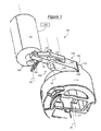
figure 1 is a perspective view of a key interlock device according to the invention; and -
figures 2 to 4 are side views of a rotation blocking system of the key interlock device offigure 1 . - Referring to
figure 1 , akey interlock device 100 according to the invention will now be described. Thekey interlock device 100 is implemented in an automotive vehicle in order to start off the engine of the automotive vehicle. - The key interlock device comprises a housing and a barrel provided with a slot intended to receive a key. The barrel is intended to rotate around a first axis A1 with respect to the housing when the correct key is inserted, and to be blocked with respect to the housing otherwise.
- The
key interlock device 100 further comprises arotation blocking system 108. - The
rotation blocking system 108 comprises acamshaft 110 forming a rotatable mobile device intended to rotate around the first axis A1. Thecamshaft 110 is provided with asocket 112 in which the barrel is received so that they are rotationally secured to each other. In this manner, both the barrel and thecamshaft 110 are intended to be rotated by the key. Thecamshaft 110 is further provided with aradial stop 114. Thecamshaft 110 is intended to transform the rotation of the key into a translation of a bolt so as to make the bolt stop or unstop a steering column. - The
rotation blocking system 108 further comprises alever 116 intended to rotate around a second axis A2. In the described example, the second axis A2 is parallel to the first axis A1. Thelever 116 is intended to take a blocking position in which it is intended to stop theradial stop 114 so as to prevent further rotation of thecamshaft 110. Thelever 116 is also intended to take a non-blocking position in which it stays away from theradial stop 114 so as to enable rotation of the camshaft around the first axis A1. In the described example, therotation blocking system 108 comprises ashaft 120 extending along the second axis A2 and on which thelever 116 is mounted. Furthermore, thelever 116 comprises twoarms first arm 122 is provided with a blockingend 126 intended to stop theradial stop 114. In the described example, the twoarms - The
rotation blocking system 108 further comprises anactuator 128 comprising aretractable part 130 intended to move along a third axis A3. In the described example, the third axis A3 is parallel to the second axis A2. Theretractable part 130 is intended to take a blocking position in which it is intended to stop thelever 116 so as to prevent rotation of thelever 116 from its blocking position to its non-blocking position. Theretractable part 130 is also intended to take a non-blocking position in which it stays away from thelever 116 so as to enable rotation of thelever 116 from its blocking position to its non-blocking position. In particular, theretractable part 130 in its non-blocking position enables thelever 116 to be in its non-blocking position. In the described example, theretractable part 130 is detached from thelever 116, so that rotation of thelever 116 does not cause movement of theretractable part 130, preventing early wearing out. Furthermore, theretractable part 130 is intended to stop thesecond arm 124 of thelever 116. In the described example, theactuator 128 comprises asolenoid 132 intended to move theretractable part 130 between its blocking position and non-blocking position. - The
rotation blocking system 108 further comprises a return mechanism intended to bring back thelever 116 towards its blocking position. In the described example, the return mechanism is areturn spring 134 connecting thesecond arm 124 of thelever 116 to the housing. - The
rotation blocking system 108 further comprises anescapement mechanism 136 intended to push thelever 116 from its blocking position toward its non-blocking position when theradial stop 114 approaches thelever 116, and in particular itsblocking end 126. - In the described example, the
escapement mechanism 136 comprises afinger 138 intended to rotate around the second axis. In the described example, thefinger 138 covers thefirst arm 122 of thelever 116. Thefinger 138 is provided with abeveled end 140 intended to slide on thecamshaft 110 so as to make thefinger 138 rotate. In the described example, thebeveled end 140 of thefinger 138 extends beyond the blockingend 126 of thelever 116, so that theradial stop 114 encounters thebeveled end 140 first. Thebeveled end 140 enables theradial stop 114 to push back thefinger 138. - The
escapement mechanism 136 further comprises a spring mechanism connecting thefinger 138 to thelever 116 and intended to push thelever 116 along with thefinger 138, toward the non-blocking position of thelever 116. In the described example, the spring mechanism is aflexible strip 142 projecting from thefinger 138 and leaning on thesecond arm 124 of thelever 116. - The
key interlock device 100 further comprises a controllingdevice 144 intended to make theactuator 128 move theretractable part 130 from its non-blocking position to its blocking position upon detection that a gear lever (not represented) of the automotive vehicle is in a parking position, and from its blocking position to its non-blocking position upon detection that the gear lever of the automotive vehicle is in another position. - Referring to
figures 2 to 4 , operation of thekey interlock device 100 will now be explained. - Referring to
figure 2 , the key is an ACC position in which theradial stop 114 is at a distance from thelever 116 and theescapement mechanism return spring 134 maintains thelever 116 in its blocking position, i.e. with its blockingend 126 on the circular course that would be followed by theradial stop 114 if the key was rotated to a STOP position. The STOP position corresponds to the position in which the key can be inserted and removed. - Referring to
figure 3 , the controllingdevice 144 detects that the gear lever is in the parking position and makes the actuator 128 move theretractable part 130 to its non-blocking position. The key is rotated towards the STOP position, which causes theradial stop 114 to rotate toward the blockingend 126 of thelever 116. However, theradial stop 114 reaches first thebeveled end 140 of thefinger 138 and, thanks to the bevel, pushes thefinger 138 away. In turn, thanks to theflexible strip 142, thefinger 138 takes thelever 116 along until thelever 116 reaches its non-blocking position. Theradial stop 114 is then not blocked anymore by thelever 116, so that the key is able to reach the STOP position. - Referring to
figure 4 , the controllingdevice 144 detects that the gear lever is in another position than the parking position and makes the actuator 128 move theretractable part 130 to its blocking position. The key is rotated towards the STOP position, which causes theradial stop 114 to rotate toward the blockingend 126 of thelever 116. Again, theradial stop 114 reaches first thebeveled end 140 of thefinger 138 and, thanks to the bevel, pushes thefinger 138 away. However, this time, thelever 116 is blocked by theretractable part 130 so that it cannot leave its blocking position. Thefinger 138 is pushed away alone, without the lever, and unveil the blockingend 126 of thelever 116. Theradial stop 114 is then blocked by this blockingend 126, so as to prevent the key to reach the STOP position. The blockedradial stop 114 applies a force F on the blockingend 126 directed toward the second axis A2 or in a direction passing within about 1 to 2 mm of the second axis A2, preferably on the side of the second axis opposite the rotation of thefinger 138. In this manner, theshaft 120 bears most of the force applied by the key. On the other hand, theflexible strip 142 applies a force f to thesecond arm 124 of thelever 116, which transmits this force f to theretractable part 130. However, thanks to the orientation of the third axis 3 with respect to the second axis A2, this force f has no component along the third axis A3, so that theactuator 128 does not need to compensate the force f. In fact, the force f can be mechanically compensated e.g. by bearings of theretractable part 130. Furthermore, the actuator does not need to be energized once theretractable part 130 is in its blocking position. Asmall actuator 128 can therefore be used, which reduces the bulk of therotation blocking system 108, as well as the electrical consumption of theactuator 128. - It should be noted than the invention is not limited by the previous description, but defined by the appended claims, which should be construed as covering all modifications and alternative constructions that may occur to the one skilled in the art which fairly fall within the basic teaching set forth herein.
- In particular, generally, the second and third axis can make any angle with each other different from a right angle, preferably inferior to 45°.
- Furthermore, the finger could rotate around another axis than the second axis, this other axis being parallel to the second axis.
Claims (10)
- Rotation blocking system (108) for a key interlock device (100) comprising:- a rotatable mobile device (110) intended to rotate around a first axis (A1) and provided with a radial stop (114),- a lever (116) intended to rotate around a second axis (A2) in order to take a blocking position in which it is intended to stop the radial stop (114) in order to prevent rotation of the rotatable mobile device (110), and a non-blocking position in which it stays away from the radial stop (114) in order to enable rotation of the rotatable mobile device (110), and- an actuator (128) comprising a retractable part (130) intended to move along a third axis (A3) in order to take a blocking position in which it is intended to stop the lever (116) so as to prevent rotation of the lever (116) from its blocking position to its non-blocking position, and a non-blocking position in which it enables the lever (116) to be in its non-blocking position,wherein the third axis (A3) makes with the second axis (A2) an angle different from a right angle.
- Rotation blocking system (108) according to claim 1, wherein the angle is inferior to 45°.
- Rotation blocking system (108) according to claim 1 or 2, wherein the third axis (A3) is parallel to the second axis (A2).
- Rotation blocking system (108) according to any one of claims 1 to 3, wherein the actuator (128) comprises a solenoid (132) intended to move the retractable part (130) between its blocking position and non-blocking position.
- Rotation blocking system (108) according to any one of claims 1 to 4, wherein the lever (116) is provided with a blocking end (126) against which the radial stop (114) is intended to apply a force directed toward the second axis (A2).
- Rotation blocking system (108) according to any one of claims 1 to 5, further comprising a escapement mechanism (138, 142) intended to push the lever (116) from its blocking position toward its non-blocking position when the radial stop (114) approaches the lever (116).
- Rotation blocking system (108) according to claim 6, wherein the escapement mechanism (138, 142) comprises:- a finger (138) intended to rotate around an axis parallel to the second axis (A2), the finger (138) being provided with a beveled end (140) on which the rotatable mobile device (110) is intended to slide so as to make the finger (138) rotate, and- a spring mechanism (142) connecting the finger (138) to the lever (116) and intended to push the lever (116) along with the finger (138), toward the non-blocking position of the lever (116).
- Rotation blocking system (108) according to claim 7, wherein the spring mechanism (142) comprises a flexible strip projecting from the finger and leaning on the lever (116).
- Rotation blocking system (108) according to claim 7 or 8, wherein the radial stop (114) is intended to slide on the beveled end (140) of the finger (138), and wherein the beveled end (140) of the finger (138) extends beyond the lever (116), so that the radial stop (114) encounters the beveled end (140) first.
- Key interlock device (100) comprising a rotation blocking system according to any one of claims 1 to 9, wherein the rotatable mobile device (110) is a camshaft intended to be rotated by a key.
Priority Applications (2)
| Application Number | Priority Date | Filing Date | Title |
|---|---|---|---|
| EP12198337.3A EP2746113B1 (en) | 2012-12-20 | 2012-12-20 | Rotation blocking system for a key interlock device and key interlock device comprising such rotation blocking system |
| PCT/EP2013/076720 WO2014095734A1 (en) | 2012-12-20 | 2013-12-16 | Rotation blocking system for a key interlock device and key interlock device comprising such rotation blocking system |
Applications Claiming Priority (1)
| Application Number | Priority Date | Filing Date | Title |
|---|---|---|---|
| EP12198337.3A EP2746113B1 (en) | 2012-12-20 | 2012-12-20 | Rotation blocking system for a key interlock device and key interlock device comprising such rotation blocking system |
Publications (2)
| Publication Number | Publication Date |
|---|---|
| EP2746113A1 true EP2746113A1 (en) | 2014-06-25 |
| EP2746113B1 EP2746113B1 (en) | 2016-11-02 |
Family
ID=47603052
Family Applications (1)
| Application Number | Title | Priority Date | Filing Date |
|---|---|---|---|
| EP12198337.3A Not-in-force EP2746113B1 (en) | 2012-12-20 | 2012-12-20 | Rotation blocking system for a key interlock device and key interlock device comprising such rotation blocking system |
Country Status (2)
| Country | Link |
|---|---|
| EP (1) | EP2746113B1 (en) |
| WO (1) | WO2014095734A1 (en) |
Citations (4)
| Publication number | Priority date | Publication date | Assignee | Title |
|---|---|---|---|---|
| DE4021168A1 (en) * | 1989-07-11 | 1991-01-24 | Volkswagen Ag | DEVICE FOR PREVENTING KEY REMOVAL FROM A STEERING LOCK |
| US5685183A (en) * | 1994-07-19 | 1997-11-11 | Kabushiki Kaisha Tokai Rika Denki Seisakusho | Vehicle locking device |
| US20030115917A1 (en) * | 2000-05-24 | 2003-06-26 | Gerd Rudolph | Anti-withdrawal device for preventing a key from being withdrawn from an ignition starter switch of an automobile |
| EP2394871A2 (en) | 2010-06-08 | 2011-12-14 | Kabushiki Kaisha Tokai Rika Denki Seisakusho | Key interlock device |
-
2012
- 2012-12-20 EP EP12198337.3A patent/EP2746113B1/en not_active Not-in-force
-
2013
- 2013-12-16 WO PCT/EP2013/076720 patent/WO2014095734A1/en not_active Ceased
Patent Citations (4)
| Publication number | Priority date | Publication date | Assignee | Title |
|---|---|---|---|---|
| DE4021168A1 (en) * | 1989-07-11 | 1991-01-24 | Volkswagen Ag | DEVICE FOR PREVENTING KEY REMOVAL FROM A STEERING LOCK |
| US5685183A (en) * | 1994-07-19 | 1997-11-11 | Kabushiki Kaisha Tokai Rika Denki Seisakusho | Vehicle locking device |
| US20030115917A1 (en) * | 2000-05-24 | 2003-06-26 | Gerd Rudolph | Anti-withdrawal device for preventing a key from being withdrawn from an ignition starter switch of an automobile |
| EP2394871A2 (en) | 2010-06-08 | 2011-12-14 | Kabushiki Kaisha Tokai Rika Denki Seisakusho | Key interlock device |
Also Published As
| Publication number | Publication date |
|---|---|
| WO2014095734A1 (en) | 2014-06-26 |
| EP2746113B1 (en) | 2016-11-02 |
Similar Documents
| Publication | Publication Date | Title |
|---|---|---|
| JP5469789B2 (en) | A lock unit having a plurality of claw portions and a claw portion having a spring | |
| US20160158945A1 (en) | Knife | |
| RU2017119448A (en) | CLAMP FOR FASTENING TO THE GUIDE RAIL OF THE OPERATING TABLE | |
| EP3222494A3 (en) | Steering column device | |
| EP3428021B1 (en) | Park-lock device for a vehicle transmission | |
| US11555339B2 (en) | Lock device | |
| US10308142B2 (en) | Locking device | |
| EP2087185B1 (en) | Vehicle handle with a security device | |
| US11274474B2 (en) | Motor vehicle lock | |
| EP2394871A3 (en) | Key interlock device | |
| US9566941B2 (en) | Adjusting device for a front lid | |
| JP6459060B2 (en) | Indirect hot wire gripping tool | |
| EP2746113B1 (en) | Rotation blocking system for a key interlock device and key interlock device comprising such rotation blocking system | |
| US10059433B2 (en) | Rotation-blocking device with simplified structure, and actuator comprising such a device | |
| US9614328B2 (en) | Locking device for a plug-in connection | |
| EP3516136B1 (en) | Compression latch with securing device | |
| US8052179B2 (en) | Unlocking device for a control device | |
| EP1569828B1 (en) | Anti-theft device for a motor vehicle, such as an electronic anti-theft device | |
| EP2910264B1 (en) | Holding device for a syringe pump | |
| EP2420419A2 (en) | Parking brake drive unit with locking device | |
| CN112204274A (en) | Parking lock device | |
| CN112204692A (en) | Operating device for circuit breaker | |
| US20160023633A1 (en) | Steering lock device | |
| US8205946B2 (en) | Actuator | |
| KR20170117597A (en) | Antenna and phase shift control device |
Legal Events
| Date | Code | Title | Description |
|---|---|---|---|
| PUAI | Public reference made under article 153(3) epc to a published international application that has entered the european phase |
Free format text: ORIGINAL CODE: 0009012 |
|
| 17P | Request for examination filed |
Effective date: 20121220 |
|
| AK | Designated contracting states |
Kind code of ref document: A1 Designated state(s): AL AT BE BG CH CY CZ DE DK EE ES FI FR GB GR HR HU IE IS IT LI LT LU LV MC MK MT NL NO PL PT RO RS SE SI SK SM TR |
|
| AX | Request for extension of the european patent |
Extension state: BA ME |
|
| R17P | Request for examination filed (corrected) |
Effective date: 20141230 |
|
| RBV | Designated contracting states (corrected) |
Designated state(s): AL AT BE BG CH CY CZ DE DK EE ES FI FR GB GR HR HU IE IS IT LI LT LU LV MC MK MT NL NO PL PT RO RS SE SI SK SM TR |
|
| 17Q | First examination report despatched |
Effective date: 20151215 |
|
| GRAP | Despatch of communication of intention to grant a patent |
Free format text: ORIGINAL CODE: EPIDOSNIGR1 |
|
| INTG | Intention to grant announced |
Effective date: 20160517 |
|
| GRAS | Grant fee paid |
Free format text: ORIGINAL CODE: EPIDOSNIGR3 |
|
| GRAA | (expected) grant |
Free format text: ORIGINAL CODE: 0009210 |
|
| AK | Designated contracting states |
Kind code of ref document: B1 Designated state(s): AL AT BE BG CH CY CZ DE DK EE ES FI FR GB GR HR HU IE IS IT LI LT LU LV MC MK MT NL NO PL PT RO RS SE SI SK SM TR |
|
| REG | Reference to a national code |
Ref country code: GB Ref legal event code: FG4D |
|
| REG | Reference to a national code |
Ref country code: AT Ref legal event code: REF Ref document number: 841491 Country of ref document: AT Kind code of ref document: T Effective date: 20161115 Ref country code: CH Ref legal event code: EP |
|
| REG | Reference to a national code |
Ref country code: IE Ref legal event code: FG4D |
|
| REG | Reference to a national code |
Ref country code: DE Ref legal event code: R096 Ref document number: 602012024784 Country of ref document: DE |
|
| REG | Reference to a national code |
Ref country code: FR Ref legal event code: PLFP Year of fee payment: 5 |
|
| PG25 | Lapsed in a contracting state [announced via postgrant information from national office to epo] |
Ref country code: LV Free format text: LAPSE BECAUSE OF FAILURE TO SUBMIT A TRANSLATION OF THE DESCRIPTION OR TO PAY THE FEE WITHIN THE PRESCRIBED TIME-LIMIT Effective date: 20161102 |
|
| RAP2 | Party data changed (patent owner data changed or rights of a patent transferred) |
Owner name: U-SHIN FRANCE |
|
| REG | Reference to a national code |
Ref country code: NL Ref legal event code: MP Effective date: 20161102 |
|
| REG | Reference to a national code |
Ref country code: LT Ref legal event code: MG4D |
|
| REG | Reference to a national code |
Ref country code: AT Ref legal event code: MK05 Ref document number: 841491 Country of ref document: AT Kind code of ref document: T Effective date: 20161102 |
|
| PG25 | Lapsed in a contracting state [announced via postgrant information from national office to epo] |
Ref country code: GR Free format text: LAPSE BECAUSE OF FAILURE TO SUBMIT A TRANSLATION OF THE DESCRIPTION OR TO PAY THE FEE WITHIN THE PRESCRIBED TIME-LIMIT Effective date: 20170203 Ref country code: NO Free format text: LAPSE BECAUSE OF FAILURE TO SUBMIT A TRANSLATION OF THE DESCRIPTION OR TO PAY THE FEE WITHIN THE PRESCRIBED TIME-LIMIT Effective date: 20170202 Ref country code: NL Free format text: LAPSE BECAUSE OF FAILURE TO SUBMIT A TRANSLATION OF THE DESCRIPTION OR TO PAY THE FEE WITHIN THE PRESCRIBED TIME-LIMIT Effective date: 20161102 Ref country code: LT Free format text: LAPSE BECAUSE OF FAILURE TO SUBMIT A TRANSLATION OF THE DESCRIPTION OR TO PAY THE FEE WITHIN THE PRESCRIBED TIME-LIMIT Effective date: 20161102 Ref country code: SE Free format text: LAPSE BECAUSE OF FAILURE TO SUBMIT A TRANSLATION OF THE DESCRIPTION OR TO PAY THE FEE WITHIN THE PRESCRIBED TIME-LIMIT Effective date: 20161102 |
|
| PG25 | Lapsed in a contracting state [announced via postgrant information from national office to epo] |
Ref country code: FI Free format text: LAPSE BECAUSE OF FAILURE TO SUBMIT A TRANSLATION OF THE DESCRIPTION OR TO PAY THE FEE WITHIN THE PRESCRIBED TIME-LIMIT Effective date: 20161102 Ref country code: PL Free format text: LAPSE BECAUSE OF FAILURE TO SUBMIT A TRANSLATION OF THE DESCRIPTION OR TO PAY THE FEE WITHIN THE PRESCRIBED TIME-LIMIT Effective date: 20161102 Ref country code: AT Free format text: LAPSE BECAUSE OF FAILURE TO SUBMIT A TRANSLATION OF THE DESCRIPTION OR TO PAY THE FEE WITHIN THE PRESCRIBED TIME-LIMIT Effective date: 20161102 Ref country code: BE Free format text: LAPSE BECAUSE OF NON-PAYMENT OF DUE FEES Effective date: 20161231 Ref country code: RS Free format text: LAPSE BECAUSE OF FAILURE TO SUBMIT A TRANSLATION OF THE DESCRIPTION OR TO PAY THE FEE WITHIN THE PRESCRIBED TIME-LIMIT Effective date: 20161102 Ref country code: ES Free format text: LAPSE BECAUSE OF FAILURE TO SUBMIT A TRANSLATION OF THE DESCRIPTION OR TO PAY THE FEE WITHIN THE PRESCRIBED TIME-LIMIT Effective date: 20161102 Ref country code: IS Free format text: LAPSE BECAUSE OF FAILURE TO SUBMIT A TRANSLATION OF THE DESCRIPTION OR TO PAY THE FEE WITHIN THE PRESCRIBED TIME-LIMIT Effective date: 20170302 Ref country code: HR Free format text: LAPSE BECAUSE OF FAILURE TO SUBMIT A TRANSLATION OF THE DESCRIPTION OR TO PAY THE FEE WITHIN THE PRESCRIBED TIME-LIMIT Effective date: 20161102 Ref country code: PT Free format text: LAPSE BECAUSE OF FAILURE TO SUBMIT A TRANSLATION OF THE DESCRIPTION OR TO PAY THE FEE WITHIN THE PRESCRIBED TIME-LIMIT Effective date: 20170302 |
|
| PG25 | Lapsed in a contracting state [announced via postgrant information from national office to epo] |
Ref country code: SK Free format text: LAPSE BECAUSE OF FAILURE TO SUBMIT A TRANSLATION OF THE DESCRIPTION OR TO PAY THE FEE WITHIN THE PRESCRIBED TIME-LIMIT Effective date: 20161102 Ref country code: RO Free format text: LAPSE BECAUSE OF FAILURE TO SUBMIT A TRANSLATION OF THE DESCRIPTION OR TO PAY THE FEE WITHIN THE PRESCRIBED TIME-LIMIT Effective date: 20161102 Ref country code: DK Free format text: LAPSE BECAUSE OF FAILURE TO SUBMIT A TRANSLATION OF THE DESCRIPTION OR TO PAY THE FEE WITHIN THE PRESCRIBED TIME-LIMIT Effective date: 20161102 Ref country code: EE Free format text: LAPSE BECAUSE OF FAILURE TO SUBMIT A TRANSLATION OF THE DESCRIPTION OR TO PAY THE FEE WITHIN THE PRESCRIBED TIME-LIMIT Effective date: 20161102 Ref country code: CZ Free format text: LAPSE BECAUSE OF FAILURE TO SUBMIT A TRANSLATION OF THE DESCRIPTION OR TO PAY THE FEE WITHIN THE PRESCRIBED TIME-LIMIT Effective date: 20161102 |
|
| REG | Reference to a national code |
Ref country code: CH Ref legal event code: PL |
|
| REG | Reference to a national code |
Ref country code: DE Ref legal event code: R097 Ref document number: 602012024784 Country of ref document: DE |
|
| PG25 | Lapsed in a contracting state [announced via postgrant information from national office to epo] |
Ref country code: IT Free format text: LAPSE BECAUSE OF FAILURE TO SUBMIT A TRANSLATION OF THE DESCRIPTION OR TO PAY THE FEE WITHIN THE PRESCRIBED TIME-LIMIT Effective date: 20161102 Ref country code: BG Free format text: LAPSE BECAUSE OF FAILURE TO SUBMIT A TRANSLATION OF THE DESCRIPTION OR TO PAY THE FEE WITHIN THE PRESCRIBED TIME-LIMIT Effective date: 20170202 Ref country code: SM Free format text: LAPSE BECAUSE OF FAILURE TO SUBMIT A TRANSLATION OF THE DESCRIPTION OR TO PAY THE FEE WITHIN THE PRESCRIBED TIME-LIMIT Effective date: 20161102 Ref country code: BE Free format text: LAPSE BECAUSE OF FAILURE TO SUBMIT A TRANSLATION OF THE DESCRIPTION OR TO PAY THE FEE WITHIN THE PRESCRIBED TIME-LIMIT Effective date: 20161102 |
|
| PLBE | No opposition filed within time limit |
Free format text: ORIGINAL CODE: 0009261 |
|
| STAA | Information on the status of an ep patent application or granted ep patent |
Free format text: STATUS: NO OPPOSITION FILED WITHIN TIME LIMIT |
|
| PG25 | Lapsed in a contracting state [announced via postgrant information from national office to epo] |
Ref country code: MC Free format text: LAPSE BECAUSE OF FAILURE TO SUBMIT A TRANSLATION OF THE DESCRIPTION OR TO PAY THE FEE WITHIN THE PRESCRIBED TIME-LIMIT Effective date: 20161102 |
|
| REG | Reference to a national code |
Ref country code: IE Ref legal event code: MM4A |
|
| 26N | No opposition filed |
Effective date: 20170803 |
|
| PG25 | Lapsed in a contracting state [announced via postgrant information from national office to epo] |
Ref country code: LI Free format text: LAPSE BECAUSE OF NON-PAYMENT OF DUE FEES Effective date: 20161231 Ref country code: LU Free format text: LAPSE BECAUSE OF NON-PAYMENT OF DUE FEES Effective date: 20161220 Ref country code: CH Free format text: LAPSE BECAUSE OF NON-PAYMENT OF DUE FEES Effective date: 20161231 |
|
| PG25 | Lapsed in a contracting state [announced via postgrant information from national office to epo] |
Ref country code: IE Free format text: LAPSE BECAUSE OF NON-PAYMENT OF DUE FEES Effective date: 20161220 Ref country code: SI Free format text: LAPSE BECAUSE OF FAILURE TO SUBMIT A TRANSLATION OF THE DESCRIPTION OR TO PAY THE FEE WITHIN THE PRESCRIBED TIME-LIMIT Effective date: 20161102 |
|
| REG | Reference to a national code |
Ref country code: FR Ref legal event code: PLFP Year of fee payment: 6 |
|
| PG25 | Lapsed in a contracting state [announced via postgrant information from national office to epo] |
Ref country code: HU Free format text: LAPSE BECAUSE OF FAILURE TO SUBMIT A TRANSLATION OF THE DESCRIPTION OR TO PAY THE FEE WITHIN THE PRESCRIBED TIME-LIMIT; INVALID AB INITIO Effective date: 20121220 |
|
| PG25 | Lapsed in a contracting state [announced via postgrant information from national office to epo] |
Ref country code: CY Free format text: LAPSE BECAUSE OF FAILURE TO SUBMIT A TRANSLATION OF THE DESCRIPTION OR TO PAY THE FEE WITHIN THE PRESCRIBED TIME-LIMIT Effective date: 20161102 Ref country code: MK Free format text: LAPSE BECAUSE OF FAILURE TO SUBMIT A TRANSLATION OF THE DESCRIPTION OR TO PAY THE FEE WITHIN THE PRESCRIBED TIME-LIMIT Effective date: 20161102 |
|
| PG25 | Lapsed in a contracting state [announced via postgrant information from national office to epo] |
Ref country code: MT Free format text: LAPSE BECAUSE OF NON-PAYMENT OF DUE FEES Effective date: 20161220 |
|
| PG25 | Lapsed in a contracting state [announced via postgrant information from national office to epo] |
Ref country code: TR Free format text: LAPSE BECAUSE OF FAILURE TO SUBMIT A TRANSLATION OF THE DESCRIPTION OR TO PAY THE FEE WITHIN THE PRESCRIBED TIME-LIMIT Effective date: 20161102 |
|
| PGFP | Annual fee paid to national office [announced via postgrant information from national office to epo] |
Ref country code: GB Payment date: 20181218 Year of fee payment: 7 |
|
| PG25 | Lapsed in a contracting state [announced via postgrant information from national office to epo] |
Ref country code: AL Free format text: LAPSE BECAUSE OF FAILURE TO SUBMIT A TRANSLATION OF THE DESCRIPTION OR TO PAY THE FEE WITHIN THE PRESCRIBED TIME-LIMIT Effective date: 20161102 |
|
| GBPC | Gb: european patent ceased through non-payment of renewal fee |
Effective date: 20191220 |
|
| PG25 | Lapsed in a contracting state [announced via postgrant information from national office to epo] |
Ref country code: GB Free format text: LAPSE BECAUSE OF NON-PAYMENT OF DUE FEES Effective date: 20191220 |
|
| PGFP | Annual fee paid to national office [announced via postgrant information from national office to epo] |
Ref country code: DE Payment date: 20201209 Year of fee payment: 9 Ref country code: FR Payment date: 20201228 Year of fee payment: 9 |
|
| REG | Reference to a national code |
Ref country code: DE Ref legal event code: R119 Ref document number: 602012024784 Country of ref document: DE |
|
| PG25 | Lapsed in a contracting state [announced via postgrant information from national office to epo] |
Ref country code: DE Free format text: LAPSE BECAUSE OF NON-PAYMENT OF DUE FEES Effective date: 20220701 |
|
| PG25 | Lapsed in a contracting state [announced via postgrant information from national office to epo] |
Ref country code: FR Free format text: LAPSE BECAUSE OF NON-PAYMENT OF DUE FEES Effective date: 20211231 |