EP2746074A1 - Pneumatic tire with built in fastener system - Google Patents
Pneumatic tire with built in fastener system Download PDFInfo
- Publication number
- EP2746074A1 EP2746074A1 EP20130197324 EP13197324A EP2746074A1 EP 2746074 A1 EP2746074 A1 EP 2746074A1 EP 20130197324 EP20130197324 EP 20130197324 EP 13197324 A EP13197324 A EP 13197324A EP 2746074 A1 EP2746074 A1 EP 2746074A1
- Authority
- EP
- European Patent Office
- Prior art keywords
- tire
- receptacle
- assembly
- passageway
- air
- Prior art date
- Legal status (The legal status is an assumption and is not a legal conclusion. Google has not performed a legal analysis and makes no representation as to the accuracy of the status listed.)
- Granted
Links
- 238000000034 method Methods 0.000 claims abstract description 11
- 241000254043 Melolonthinae Species 0.000 claims abstract description 9
- 239000012530 fluid Substances 0.000 claims abstract description 9
- 238000004891 communication Methods 0.000 claims abstract description 7
- 239000013536 elastomeric material Substances 0.000 claims abstract description 4
- 238000000465 moulding Methods 0.000 claims abstract description 3
- 239000002184 metal Substances 0.000 claims description 5
- 239000004677 Nylon Substances 0.000 claims description 4
- 229920001778 nylon Polymers 0.000 claims description 4
- 239000004033 plastic Substances 0.000 claims description 4
- 229920003023 plastic Polymers 0.000 claims description 4
- 229910001369 Brass Inorganic materials 0.000 claims 2
- 239000004699 Ultra-high molecular weight polyethylene Substances 0.000 claims 2
- 239000010951 brass Substances 0.000 claims 2
- 229920000785 ultra high molecular weight polyethylene Polymers 0.000 claims 2
- 229920001971 elastomer Polymers 0.000 description 16
- 239000005060 rubber Substances 0.000 description 14
- 230000002572 peristaltic effect Effects 0.000 description 9
- 238000012423 maintenance Methods 0.000 description 7
- 239000000463 material Substances 0.000 description 6
- 239000000853 adhesive Substances 0.000 description 5
- 230000001070 adhesive effect Effects 0.000 description 5
- 229920001875 Ebonite Polymers 0.000 description 4
- 239000011324 bead Substances 0.000 description 3
- 238000009434 installation Methods 0.000 description 3
- 229920010741 Ultra High Molecular Weight Polyethylene (UHMWPE) Polymers 0.000 description 2
- 150000001875 compounds Chemical class 0.000 description 2
- 239000000806 elastomer Substances 0.000 description 2
- 238000004073 vulcanization Methods 0.000 description 2
- KVBYPTUGEKVEIJ-UHFFFAOYSA-N benzene-1,3-diol;formaldehyde Chemical compound O=C.OC1=CC=CC(O)=C1 KVBYPTUGEKVEIJ-UHFFFAOYSA-N 0.000 description 1
- 238000010276 construction Methods 0.000 description 1
- 230000008602 contraction Effects 0.000 description 1
- 230000003247 decreasing effect Effects 0.000 description 1
- 230000001419 dependent effect Effects 0.000 description 1
- 239000004744 fabric Substances 0.000 description 1
- 239000000835 fiber Substances 0.000 description 1
- 238000003780 insertion Methods 0.000 description 1
- 230000037431 insertion Effects 0.000 description 1
- 239000004816 latex Substances 0.000 description 1
- 229920000126 latex Polymers 0.000 description 1
- 230000013011 mating Effects 0.000 description 1
- 239000000203 mixture Substances 0.000 description 1
- 230000037361 pathway Effects 0.000 description 1
- 229920001296 polysiloxane Polymers 0.000 description 1
- 230000001105 regulatory effect Effects 0.000 description 1
- 230000002787 reinforcement Effects 0.000 description 1
- 239000012815 thermoplastic material Substances 0.000 description 1
Images





Classifications
-
- B—PERFORMING OPERATIONS; TRANSPORTING
- B60—VEHICLES IN GENERAL
- B60C—VEHICLE TYRES; TYRE INFLATION; TYRE CHANGING; CONNECTING VALVES TO INFLATABLE ELASTIC BODIES IN GENERAL; DEVICES OR ARRANGEMENTS RELATED TO TYRES
- B60C19/00—Tyre parts or constructions not otherwise provided for
-
- B—PERFORMING OPERATIONS; TRANSPORTING
- B60—VEHICLES IN GENERAL
- B60C—VEHICLE TYRES; TYRE INFLATION; TYRE CHANGING; CONNECTING VALVES TO INFLATABLE ELASTIC BODIES IN GENERAL; DEVICES OR ARRANGEMENTS RELATED TO TYRES
- B60C23/00—Devices for measuring, signalling, controlling, or distributing tyre pressure or temperature, specially adapted for mounting on vehicles; Arrangement of tyre inflating devices on vehicles, e.g. of pumps or of tanks; Tyre cooling arrangements
- B60C23/10—Arrangement of tyre-inflating pumps mounted on vehicles
- B60C23/12—Arrangement of tyre-inflating pumps mounted on vehicles operated by a running wheel
- B60C23/121—Arrangement of tyre-inflating pumps mounted on vehicles operated by a running wheel the pumps being mounted on the tyres
- B60C23/123—Elongate peristaltic pumps
-
- B—PERFORMING OPERATIONS; TRANSPORTING
- B60—VEHICLES IN GENERAL
- B60C—VEHICLE TYRES; TYRE INFLATION; TYRE CHANGING; CONNECTING VALVES TO INFLATABLE ELASTIC BODIES IN GENERAL; DEVICES OR ARRANGEMENTS RELATED TO TYRES
- B60C23/00—Devices for measuring, signalling, controlling, or distributing tyre pressure or temperature, specially adapted for mounting on vehicles; Arrangement of tyre inflating devices on vehicles, e.g. of pumps or of tanks; Tyre cooling arrangements
- B60C23/10—Arrangement of tyre-inflating pumps mounted on vehicles
- B60C23/12—Arrangement of tyre-inflating pumps mounted on vehicles operated by a running wheel
- B60C23/135—Arrangement of tyre-inflating pumps mounted on vehicles operated by a running wheel activated due to tyre deformation
-
- B—PERFORMING OPERATIONS; TRANSPORTING
- B29—WORKING OF PLASTICS; WORKING OF SUBSTANCES IN A PLASTIC STATE IN GENERAL
- B29D—PRODUCING PARTICULAR ARTICLES FROM PLASTICS OR FROM SUBSTANCES IN A PLASTIC STATE
- B29D30/00—Producing pneumatic or solid tyres or parts thereof
- B29D30/0061—Accessories, details or auxiliary operations not otherwise provided for
- B29D2030/0072—Attaching fasteners to tyres, e.g. patches, in order to connect devices to tyres
-
- Y—GENERAL TAGGING OF NEW TECHNOLOGICAL DEVELOPMENTS; GENERAL TAGGING OF CROSS-SECTIONAL TECHNOLOGIES SPANNING OVER SEVERAL SECTIONS OF THE IPC; TECHNICAL SUBJECTS COVERED BY FORMER USPC CROSS-REFERENCE ART COLLECTIONS [XRACs] AND DIGESTS
- Y10—TECHNICAL SUBJECTS COVERED BY FORMER USPC
- Y10T—TECHNICAL SUBJECTS COVERED BY FORMER US CLASSIFICATION
- Y10T152/00—Resilient tires and wheels
- Y10T152/10—Tires, resilient
- Y10T152/10495—Pneumatic tire or inner tube
Definitions
- the invention relates generally to tires and securing parts to a pneumatic tire.
- Structures in a pneumatic tire may require the attaching or securing of certain parts, functional devices, and connectors to a rubber part of the tire (e.g., the innerliner).
- the structures of an air maintenance tire typically include components such as pressure regulating valves, check valves, tubing or bridge connectors and filters to be attached to the tire sidewall within the tire cavity.
- Such structures typically encounter high stresses during the operating conditions of the tire. Thus, strong attachment of such structures is desired for proper operation of the system as a whole.
- the invention relates to a tire assembly in accordance with claim 1, to a tire in accordance with claim 11 and to a method in accordance with claim 14.
- the invention provides in a first aspect a tire comprising: an interior surface, wherein a receptacle is mounted on the interior surface of the tire, the receptacle having a raised hump formed on the interior surface, and having a mechanical fastener system formed within the raised hump.
- the invention provides in a second aspect a method of securing an object to a tire, including the steps of: attaching two or more concentric layers of elastomeric material to a green tire; inserting a first part of a mechanical fastener system into a hole of the two or more concentric layers; curing the green tire to form a cured tire and to secure the first part of the two piece mechanical fastening system to the cured tire; attaching the object to a second part of the two piece mechanical fastening system; and attaching the first part of the two-piece mechanical fastening system to the second part of the two-piece mechanical fastening system.
- the invention provides in a third aspect a method of securing an object to a tire, including the steps of: attaching two or more concentric layers of elastomeric material to a green tire; molding a first part of a mechanical fastener system into a hole of the two or more concentric layers; curing the green tire to form a cured tire; attaching the object to a second part of the two piece mechanical fastening system; and attaching the first part of the two-piece mechanical fastening system to the molded in second part of the two-piece mechanical fastening system.
- the invention provides in a fourth aspect a tire assembly comprising a tire having a toroidal tire cavity for containing pressurized air; an elongate integral air passageway contained within a flexible tire component, the air passageway extending between an air inlet cavity and an air outlet cavity in the flexible tire component, the air passageway extending for at least a partial circumferential path around the tire; and a receptacle mounted on the interior surface of the tire, the receptacle has a first part of a two part fastener system, wherein the receptacle has a passageway in fluid communication with the air passageway within the flexible tire component.
- Figure 1 illustrates a partial inside view of a tire in the sidewall region which illustrates a first and second raised receptacle 100, 102 of the present invention.
- the raised receptacles 100, 102 are preferably integrally molded with the green tire during vulcanization, and include a raised surface or hump 108, 109 formed on the interior surface of the tire. While the receptacles are shown in the tire sidewall area, the receptacles may be located anywhere on the inside or exterior surface of the tire.
- Each raised hump 108, 109 includes a first part of a fastener mechanism which is preferably centrally located.
- the first part of a fastener mechanism is a threaded hole 104, 106.
- Devices such as valves, transducers, filters or other devices have a second part of a fastener system which in this example is a threaded male end, may be secured or screwed into the receptacle as described in more detail, below.
- the raised receptacle is not limited to a threaded hole, and may include other locking fastener systems known to those skilled in the art.
- the first part of a fastener mechanism may be a bayonet-style socket that is inserted into the assembly and molded into the tire.
- the device to be mounted may include the second part of the fastener system which is a bayonet connector for reception into mating engagement with the bayonet socket.
- Other fastener systems may include snap in fastener, key, spline joint, or retaining ring.
- Velcro hook and loop strip may also be used as the fastener system.
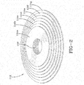
- Figure 2 illustrates an assembly 112 of concentric stacked layers 114a-g used to form the humps 108 of the present invention. While the invention is illustrated as concentric rings, the invention is not limited to the ring shape, as other shapes such as squares, triangles; etc would work for the invention.
- the assembly 112 is formed of concentric layers of material, wherein the material may be: green rubber or uncured elastomeric or thermoplastic materials or blends thereof.
- the rubber may be reinforced with short fibers or fabric reinforcements.
- the layers are formed of a green hard rubber compound having a Shore A hardness in the range of 40 to 100, and more preferably in the range of 50 to 90 or 60 to 80.
- Each layer 114a-g has an aligned interior hole 116 having the same interior diameter as the other layers 114a-g.
- the layers 114a-f are arranged in a pyramid with layers of decreasing outer dimensions such that the outermost layer 114a has the smallest outer diameter.
- the layers forming the assembly 112 are assembled as shown in Figure 2 and then placed inside a green tire adjacent the innerliner, as shown in Figure 3 .
- the assembly 112 may be placed in the sidewall area near the chafer.
- the assembly 112 is temporarily secured to the innerliner using hot gum rubber or rubber adhesive.
- a screw such as an M5 screw 120 is inserted into hole 116 of the assembly and may be secured using rubber adhesive.
- the hole diameter 116 is preferably sized so that the hole sidewalls abut the screw surface.
- the green tire is then vulcanized in a tire mold as known to those skilled in the art.
- the concentric assembly has been vulcanized to form the humps 108, 109 which are integrally bonded to the tire inner surface.
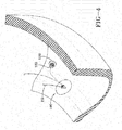
- Figure 4 illustrates that the threads of the screw 120 has formed a threaded passageway molded in the cured tire after removal of screw 120.
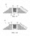
- the concentric layer assembly 112 may be used in conjunction with an insert 200 forming an assembly 300 which is a first part of a fastener system.
- the insert 200 may be a cylindrically shaped sleeve having an internal hole 202 (or other fastener mechanism (not shown)). Hole 202 extends completely through the insert 200.
- the insert 200 is inserted in hole 116 of assembly 112 prior to cure.
- the insert 200 internal hole 202 preferably is partially threaded 204 to receive a second part of a fastener system such as a threaded end of a valve or other device.
- the assembly 300 is then affixed to a desired green tire surface such as the internal portion of the sidewall using adhesive.
- a removable screw is preferably screwed into hole 116 prior to cure.
- the assembly 300 is permanently molded into the tire with the exception of the removable screw during vulcanization.
- the insert 200 may be made of rubber, preferably green rubber, elastomer, metal, plastic, nylon or ultra high molecular weight polyethylene (UHMWPE) or other known material or combinations thereof.
- the insert may optionally include threads or protrusions on the exterior surface.
- the insert may further include a flanged outer end (not shown) in order to secure the insert to the tire.
- the outer surface of the insert may optionally be roughened and coated with a suitable adhesive such as resorcinol formaldehyde latex (RFL) commonly known as "dip".
- RFL resorcinol formaldehyde latex
- the outer surface of the insert may further include ridges, flanges, extensions, threads or other mechanical means in addition to the selected RFL to retain it into the rubber of the tire sidewall.
- a third embodiment of an assembly 400 is shown in Figure 10 .
- the assembly includes a plurality of annular rings 404 through 414 wherein each ring has an inner hole which encircles another ring.
- ring 414 encircles the outer surface of ring 412
- ring 412 has an inner hole which encircles ring 410 and so on.
- Each ring may have a height H.
- the inner most ring 404 is the tallest ring, and the outermost ring is the shortest.
- the rings are arranged such that the tallest rings are innermost and successively decrease in height towards the outermost ring.
- the assembly includes an optional insert 200 as described above. The insert is mounted in hole 402 of annular ring 404.
- Annular rings 404 and 406 are preferably made of a hard rubber such as known to those skilled in the art to form an apex. Rings 408 and 410 are preferably formed of a hard rubber such as a chafer. Rings 412 and 414 are preferably formed of a rubber used to make ply. Thus the innermost rings 404, 406 are formed of a green hard rubber compound having a Shore A hardness in the range of about 40 to about 100, and more preferably in the range of about 50 to about 90.
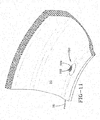
- a one piece unit 500 having a pyramidal shape as shown in Figure 11 may be used.
- the one piece unit may be premolded to a desired shape such as a pyramid.
- the one piece unit has a center hole 502 which may be threaded 504.
- a removable screw may be placed in center hole 502 and used to mold in threads when the assembly 500 is vulcanized in the tire.
- the one piece unit may optionally include a center sleeve 506 which may be made of a different material than the one piece unit.
- a mold to form the shape of the desired fastener may be used, or the fastener device itself may be permanently molded into the tire by insertion prior to cure.
- the assembly 500 is permanently molded into the tire by affixing to a desired green tire surface such as the internal portion of the sidewall using adhesive.
- a removable screw is preferably screwed into hole 502 prior to cure.
- the assembly 500 is permanently molded into the tire with the exception of the removable screw.
- the center sleeve may be made of rubber, preferably green rubber, elastomer, metal, plastic, nylon or ultra high molecular weight polyethylene (UHMWPE) or other known material or combinations thereof.
- the sleeve may optionally include threads or protrusions on the exterior surface.
- the sleeve may further include a flanged outer end (not shown) in order to secure the sleeve to the tire.
- the outer surface of the sleeve may optionally be roughened and coated with the selected RFL.
- the outer surface of the sleeve may further include ridges, flanges, extensions, threads or other mechanical means in addition to the selected RFL to retain it into the rubber of the tire sidewall.
- the following method steps are applicable for the installation of the threaded receptacle 100 to be used in conjunction with the special case of a tire with a peristaltic pump assembly.
- the receptacles may be used to install pressure regulators, valves, filter and combinations thereof.
- the threaded receptacles must be installed in such a manner so that the devices installed in the receptacles are in fluid communication with the pump fluid passageway in the tire.
- a tire having an air maintenance assembly system 10 is shown provided within one ( FIG. 7 ) or both (not shown) sidewalls 14, 16 of the tire 12.
- the tire also has a tread 18, as bead 22 and an apex 26. It may be mounted on a rim 36 having a rim surface 40.
- the air maintenance assembly 42 may be configured to extend between an air entry or inlet cavity 44 and an air exit or outlet cavity 46 within the sidewall 14, 16.
- the air maintenance assembly 42 may incorporate a thin hollow tube 94 within a flexible tire component, such as the chafer 28, wherein the tube is formed during tire construction with a strip, which is them removed post cure to form the tube 94.
- the location selected for the hollow tube or passageway within the tire 12 may be within a tire component residing within a high flex region of the tire, sufficient to progressively collapse the peristaltic internal hollow tube as the tire rotates under load thereby conveying air along the hollow tube from the inlet cavity 44 to the outlet cavity 46 and the tire cavity 20.
- This AMT (Air Maintenance Tire) assembly 42 may thus function as an internal peristaltic air pump for the tire 12.
- the pump is shown as a 180 degree configuration, but could be any desired configuration such as 90 degrees, 270, 360.
- a flexible green (uncured) tire component such as a chafer 28, may have a groove formed therein wherein the groove has opposed groove walls.
- a silicone strip, cable, or wire (hereinafter strip) 58 is placed in the groove between the groove walls, and then the walls stitched closed.
- the strip may optionally be encased in green rubber prior to placement within the tire component groove.
- the chafer or tire component with the strip is installed in the tire during the tire building process. Holes are punched in the green tire at the location of the inlet 44 and outlet 46.
- the strip 58 is preferably dimensioned such that the ends 59, 61 extend a distance beyond the inlet/outlet holes 44, 46 at opposite ends of the chafer strip.
- a concentric assembly 112 is positioned at the location of the punched holes 44, 46 on the inside surface of the tire.
- a first end 59 of the strip is positioned so that it extends through inlet punched hole 46 on the interior surface of the tire, and through hole 116 of concentric ring assembly 112.
- the threaded end of a screw or other fastener system is positioned in hole 116, wherein the strip end 59 is inserted through a central hole of the screw or fastener system.
- Figure 3 illustrates the assembled configuration pre-cure. The procedure is repeated for outlet punched hole 44.
- the strip be threaded through each hole 44, 46 and through the central hole 122 of screw 120 in order to form a continuous molded in passageway from each of the threaded receptacles to the pump tube 94.
- the strip is removed forming a continuous air passageway 94 from the threaded receptacle at the inlet end 46, through the interior of the tire sidewall, and to the threaded receptacle at the outlet.
- an inlet control or pressure regulator valve (not shown) having a male threaded end is threadably received in the inlet end receptacle. The inlet control valve controls the air flow into the pump.
- a check valve having a male threaded end (not shown) is screwed into the receptacle located at the pump outlet end.
- the check valve is in fluid communication with the tire cavity so that fluid may flow into the tire cavity to maintain the tire pressure at a desired pressure, while preventing cavity air from back flowing into the pump.
- This continuous air passageway ensures that upon installation of a valve or filter into the threaded receptacle, that the valve, filter or other component is in fluid communication with the pump passageway.
- the air maintenance assembly 42 may represent a peristaltic air pump system in which the compressible air passageway progressively pumps air along the passageway from the inlet to the outlet and the tire cavity 20 for maintaining internal tire cavity pressure at a required level.
- the inlet and the outlet may be positioned in the range of about 90 to 360 degrees apart, separated by the internal air passageway.
- the tire 12 may rotate in a direction of rotation and cause a footprint to be formed against the contact/ground surface.
- a compressive force may be directed into the tire 12 from the footprint and may act to flatten a segment of the air passageway adjacent the footprint. Flattening of the segment of the passageway may force air from the segment along the internal passageway in a direction toward the pump outlet.
- the sequential flattening of the air passageway segment by segment may thus cause evacuated air from the flattened segments to be pumped to the pump outlet.
- the outlet assembly may open to allow air to flow through the outlet assembly into the tire cavity 20. This air may thereby serve to re-inflate the tire 12 to a desired pressure level as needed.
- flattened tube segments may be sequentially refilled by air flowing into the inlet assembly along the passageway.
- the inflow of air from the inlet may continue until the outlet becomes adjacent the tire footprint.
- the inlet will eventually pass the tire footprint against ground surface, and airflow may resume to the outlet along the passageway.
- the above-described cycle may then be repeated for each tire revolution, "half" depending on the pump length of each rotation resulting in pumped air going to the tire cavity 20 and "half" depending on the pump length of the rotation resulting in pumped air being directed back out the inlet.
- the subject tire assembly and its peristaltic pump assembly 42 may function in like manner in either direction of rotation.
- the peristaltic pump assembly 42 is accordingly bi-directional and equally functional with the assembly moving in a forward or an opposite, reverse direction of rotation.
Landscapes
- Engineering & Computer Science (AREA)
- Mechanical Engineering (AREA)
- Tires In General (AREA)
- Tyre Moulding (AREA)
Abstract
Description
- The invention relates generally to tires and securing parts to a pneumatic tire.
- Structures in a pneumatic tire may require the attaching or securing of certain parts, functional devices, and connectors to a rubber part of the tire (e.g., the innerliner). In particular, the structures of an air maintenance tire typically include components such as pressure regulating valves, check valves, tubing or bridge connectors and filters to be attached to the tire sidewall within the tire cavity. Such structures typically encounter high stresses during the operating conditions of the tire. Thus, strong attachment of such structures is desired for proper operation of the system as a whole.
- The invention relates to a tire assembly in accordance with claim 1, to a tire in accordance with claim 11 and to a method in accordance with
claim 14. - Dependent claims refer to preferred embodiments of the invention.
- The invention provides in a first aspect a tire comprising: an interior surface, wherein a receptacle is mounted on the interior surface of the tire, the receptacle having a raised hump formed on the interior surface, and having a mechanical fastener system formed within the raised hump.
- The invention provides in a second aspect a method of securing an object to a tire, including the steps of: attaching two or more concentric layers of elastomeric material to a green tire; inserting a first part of a mechanical fastener system into a hole of the two or more concentric layers; curing the green tire to form a cured tire and to secure the first part of the two piece mechanical fastening system to the cured tire; attaching the object to a second part of the two piece mechanical fastening system; and attaching the first part of the two-piece mechanical fastening system to the second part of the two-piece mechanical fastening system.
- The invention provides in a third aspect a method of securing an object to a tire, including the steps of: attaching two or more concentric layers of elastomeric material to a green tire; molding a first part of a mechanical fastener system into a hole of the two or more concentric layers; curing the green tire to form a cured tire; attaching the object to a second part of the two piece mechanical fastening system; and attaching the first part of the two-piece mechanical fastening system to the molded in second part of the two-piece mechanical fastening system.
- The invention provides in a fourth aspect a tire assembly comprising a tire having a toroidal tire cavity for containing pressurized air; an elongate integral air passageway contained within a flexible tire component, the air passageway extending between an air inlet cavity and an air outlet cavity in the flexible tire component, the air passageway extending for at least a partial circumferential path around the tire; and a receptacle mounted on the interior surface of the tire, the receptacle has a first part of a two part fastener system, wherein the receptacle has a passageway in fluid communication with the air passageway within the flexible tire component.
-
- "Axial" and "axially" means lines or directions that are parallel to the axis of rotation of the tire.
- "Chafer" is a narrow strip of material placed around the outside of a tire bead to protect the cord plies from wearing and cutting against the rim and distribute the flexing above the rim.
- "Footprint" means the contact patch or area of contact of the tire tread with a flat surface at zero speed and under normal load and pressure.
- "Lateral" means an axial direction.
- "Peristaltic" means operating by means of wave-like contractions that propel contained matter, such as air, along tubular pathways.
- "Radial" and "radially" means directions radially toward or away from the axis of rotation of the tire.
- The invention will be described by way of example and with reference to the accompanying drawings in which:
-
Figure 1 illustrates a partial inside view of a tire in the sidewall region showing two threaded receptacles of the present invention. -
Figure 2 illustrates anassembly 112 ofconcentric rings 114a-g used to form the raisedhumps 108 of the threaded receptacles ofFigure 1 . -
Figure 3 illustrates the assembly placed in a green tire sidewall area. -
Figure 4 illustrates a close-up view of the molded threaded passageway formed in the threadedreceptacles -
Figure 5 illustrates a tire assembly with air maintenance pump assembly. -
Figure 6 illustrates a green tire sidewall during the installation of the pump. -
Figure 7 illustrates a cross-sectional view of a portion of a tire bead area showing the pump tube location. -
Figure 8 illustrates a schematic of the concentric ring assembly mounted on the tire, prior to cure, shown with a screw inserted therein and a strip extending from the tire sidewall to the hole of the concentric ring assembly. -
Figure 9 illustrates a front view of alternate embodiment of the invention. -
Figure 10 illustrates a front view of a second alternate embodiment of the invention. -
Figure 11 is a perspective view of a third alternate embodiment. -
Figure 12 is a cross-sectional view ofFigure 11 . -
Figure 1 illustrates a partial inside view of a tire in the sidewall region which illustrates a first and second raisedreceptacle receptacles hump - Each raised
hump hole -
Figure 2 illustrates anassembly 112 of concentric stackedlayers 114a-g used to form thehumps 108 of the present invention. While the invention is illustrated as concentric rings, the invention is not limited to the ring shape, as other shapes such as squares, triangles; etc would work for the invention. Theassembly 112 is formed of concentric layers of material, wherein the material may be: green rubber or uncured elastomeric or thermoplastic materials or blends thereof. The rubber may be reinforced with short fibers or fabric reinforcements. Preferably, the layers are formed of a green hard rubber compound having a Shore A hardness in the range of 40 to 100, and more preferably in the range of 50 to 90 or 60 to 80. Eachlayer 114a-g has an alignedinterior hole 116 having the same interior diameter as theother layers 114a-g. Starting with theinnermost layer 114g with the largest outer dimension, thelayers 114a-f are arranged in a pyramid with layers of decreasing outer dimensions such that theoutermost layer 114a has the smallest outer diameter. - The layers forming the
assembly 112 are assembled as shown inFigure 2 and then placed inside a green tire adjacent the innerliner, as shown inFigure 3 . For an application such as a peristaltic pump assembly, theassembly 112 may be placed in the sidewall area near the chafer. Theassembly 112 is temporarily secured to the innerliner using hot gum rubber or rubber adhesive. A screw such as anM5 screw 120 is inserted intohole 116 of the assembly and may be secured using rubber adhesive. Thehole diameter 116 is preferably sized so that the hole sidewalls abut the screw surface. - The green tire is then vulcanized in a tire mold as known to those skilled in the art. After the tire has been vulcanized, the concentric assembly has been vulcanized to form the
humps Figure 4 illustrates that the threads of thescrew 120 has formed a threaded passageway molded in the cured tire after removal ofscrew 120. - As shown in
Figure 9 , theconcentric layer assembly 112 may be used in conjunction with aninsert 200 forming anassembly 300 which is a first part of a fastener system. Theinsert 200 may be a cylindrically shaped sleeve having an internal hole 202 (or other fastener mechanism (not shown)).Hole 202 extends completely through theinsert 200. Theinsert 200 is inserted inhole 116 ofassembly 112 prior to cure. Theinsert 200internal hole 202 preferably is partially threaded 204 to receive a second part of a fastener system such as a threaded end of a valve or other device. Theassembly 300 is then affixed to a desired green tire surface such as the internal portion of the sidewall using adhesive. A removable screw is preferably screwed intohole 116 prior to cure. Theassembly 300 is permanently molded into the tire with the exception of the removable screw during vulcanization. - The
insert 200 may be made of rubber, preferably green rubber, elastomer, metal, plastic, nylon or ultra high molecular weight polyethylene (UHMWPE) or other known material or combinations thereof. The insert may optionally include threads or protrusions on the exterior surface. The insert may further include a flanged outer end (not shown) in order to secure the insert to the tire. The outer surface of the insert may optionally be roughened and coated with a suitable adhesive such as resorcinol formaldehyde latex (RFL) commonly known as "dip". The outer surface of the insert may further include ridges, flanges, extensions, threads or other mechanical means in addition to the selected RFL to retain it into the rubber of the tire sidewall. - A third embodiment of an
assembly 400 is shown inFigure 10 . The assembly includes a plurality ofannular rings 404 through 414 wherein each ring has an inner hole which encircles another ring. Thus ring 414 encircles the outer surface ofring 412, andring 412 has an inner hole which encirclesring 410 and so on. Each ring may have a height H. Preferably the innermost ring 404 is the tallest ring, and the outermost ring is the shortest. The rings are arranged such that the tallest rings are innermost and successively decrease in height towards the outermost ring. The assembly includes anoptional insert 200 as described above. The insert is mounted inhole 402 ofannular ring 404. Annular rings 404 and 406 are preferably made of a hard rubber such as known to those skilled in the art to form an apex.Rings Rings innermost rings - Alternatively, in place of the concentric
layered assembly 112, a onepiece unit 500 having a pyramidal shape as shown inFigure 11 may be used. The one piece unit may be premolded to a desired shape such as a pyramid. The one piece unit has acenter hole 502 which may be threaded 504. A removable screw may be placed incenter hole 502 and used to mold in threads when theassembly 500 is vulcanized in the tire. The one piece unit may optionally include acenter sleeve 506 which may be made of a different material than the one piece unit. In place of the screw, a mold to form the shape of the desired fastener may be used, or the fastener device itself may be permanently molded into the tire by insertion prior to cure. Theassembly 500 is permanently molded into the tire by affixing to a desired green tire surface such as the internal portion of the sidewall using adhesive. A removable screw is preferably screwed intohole 502 prior to cure. Theassembly 500 is permanently molded into the tire with the exception of the removable screw. - The center sleeve may be made of rubber, preferably green rubber, elastomer, metal, plastic, nylon or ultra high molecular weight polyethylene (UHMWPE) or other known material or combinations thereof. The sleeve may optionally include threads or protrusions on the exterior surface. The sleeve may further include a flanged outer end (not shown) in order to secure the sleeve to the tire. The outer surface of the sleeve may optionally be roughened and coated with the selected RFL. The outer surface of the sleeve may further include ridges, flanges, extensions, threads or other mechanical means in addition to the selected RFL to retain it into the rubber of the tire sidewall.
- The following method steps are applicable for the installation of the threaded
receptacle 100 to be used in conjunction with the special case of a tire with a peristaltic pump assembly. The receptacles may be used to install pressure regulators, valves, filter and combinations thereof. Thus, the threaded receptacles must be installed in such a manner so that the devices installed in the receptacles are in fluid communication with the pump fluid passageway in the tire. - Referring initially to
FIG. 5 , a tire having an airmaintenance assembly system 10 is shown provided within one (FIG. 7 ) or both (not shown) sidewalls 14, 16 of thetire 12. The tire also has atread 18, asbead 22 and an apex 26. It may be mounted on arim 36 having arim surface 40. Theair maintenance assembly 42 may be configured to extend between an air entry orinlet cavity 44 and an air exit oroutlet cavity 46 within thesidewall air maintenance assembly 42 may incorporate a thinhollow tube 94 within a flexible tire component, such as thechafer 28, wherein the tube is formed during tire construction with a strip, which is them removed post cure to form thetube 94. The location selected for the hollow tube or passageway within thetire 12 may be within a tire component residing within a high flex region of the tire, sufficient to progressively collapse the peristaltic internal hollow tube as the tire rotates under load thereby conveying air along the hollow tube from theinlet cavity 44 to theoutlet cavity 46 and thetire cavity 20. This AMT (Air Maintenance Tire)assembly 42 may thus function as an internal peristaltic air pump for thetire 12. The pump is shown as a 180 degree configuration, but could be any desired configuration such as 90 degrees, 270, 360. - A flexible green (uncured) tire component such as a
chafer 28, may have a groove formed therein wherein the groove has opposed groove walls. A silicone strip, cable, or wire (hereinafter strip) 58 is placed in the groove between the groove walls, and then the walls stitched closed. The strip may optionally be encased in green rubber prior to placement within the tire component groove. The chafer or tire component with the strip is installed in the tire during the tire building process. Holes are punched in the green tire at the location of theinlet 44 andoutlet 46. Thestrip 58 is preferably dimensioned such that the ends 59, 61 extend a distance beyond the inlet/outlet holes 44, 46 at opposite ends of the chafer strip. - A
concentric assembly 112 is positioned at the location of the punchedholes first end 59 of the strip is positioned so that it extends through inlet punchedhole 46 on the interior surface of the tire, and throughhole 116 ofconcentric ring assembly 112. The threaded end of a screw or other fastener system is positioned inhole 116, wherein thestrip end 59 is inserted through a central hole of the screw or fastener system.Figure 3 illustrates the assembled configuration pre-cure. The procedure is repeated for outlet punchedhole 44. It is important that the strip be threaded through eachhole central hole 122 ofscrew 120 in order to form a continuous molded in passageway from each of the threaded receptacles to thepump tube 94. After the tire is cured, the strip is removed forming acontinuous air passageway 94 from the threaded receptacle at theinlet end 46, through the interior of the tire sidewall, and to the threaded receptacle at the outlet. Preferably, an inlet control or pressure regulator valve (not shown) having a male threaded end is threadably received in the inlet end receptacle. The inlet control valve controls the air flow into the pump. It is also preferred that a check valve having a male threaded end (not shown) is screwed into the receptacle located at the pump outlet end. The check valve is in fluid communication with the tire cavity so that fluid may flow into the tire cavity to maintain the tire pressure at a desired pressure, while preventing cavity air from back flowing into the pump. This continuous air passageway ensures that upon installation of a valve or filter into the threaded receptacle, that the valve, filter or other component is in fluid communication with the pump passageway. - As described above, the
air maintenance assembly 42 may represent a peristaltic air pump system in which the compressible air passageway progressively pumps air along the passageway from the inlet to the outlet and thetire cavity 20 for maintaining internal tire cavity pressure at a required level. The inlet and the outlet may be positioned in the range of about 90 to 360 degrees apart, separated by the internal air passageway. Thetire 12 may rotate in a direction of rotation and cause a footprint to be formed against the contact/ground surface. A compressive force may be directed into thetire 12 from the footprint and may act to flatten a segment of the air passageway adjacent the footprint. Flattening of the segment of the passageway may force air from the segment along the internal passageway in a direction toward the pump outlet. - The sequential flattening of the air passageway segment by segment may thus cause evacuated air from the flattened segments to be pumped to the pump outlet. When the air flow pressure is sufficient against the permanent outlet assembly, the outlet assembly may open to allow air to flow through the outlet assembly into the
tire cavity 20. This air may thereby serve to re-inflate thetire 12 to a desired pressure level as needed. - With the
tire 12 continuing to rotate, flattened tube segments may be sequentially refilled by air flowing into the inlet assembly along the passageway. The inflow of air from the inlet may continue until the outlet becomes adjacent the tire footprint. When thetire 12 rotates further, the inlet will eventually pass the tire footprint against ground surface, and airflow may resume to the outlet along the passageway. - The above-described cycle may then be repeated for each tire revolution, "half" depending on the pump length of each rotation resulting in pumped air going to the
tire cavity 20 and "half" depending on the pump length of the rotation resulting in pumped air being directed back out the inlet. It will be appreciated that the subject tire assembly and itsperistaltic pump assembly 42 may function in like manner in either direction of rotation. Theperistaltic pump assembly 42 is accordingly bi-directional and equally functional with the assembly moving in a forward or an opposite, reverse direction of rotation.
Claims (15)
- A tire assembly comprising a tire (12) having a toroidal tire cavity (20) for containing pressurized air and an elongate integral air passageway (94) contained within a flexible tire component such as a tire chafer (28), the air passageway (94) extending between an air inlet cavity (44) and an air outlet cavity (46) in the flexible tire component and extending for at least a partial circumferential path around the tire (12), and at least one receptacle (100, 102) mounted on a surface, preferably an interior surface, of the tire (12), wherein the receptacle (100, 102) has a first part of a two part fastener system, and has a passageway (104, 106) in fluid communication with the air passageway (94) within the flexible tire component.
- The tire assembly of claim 1 wherein the receptacle (100, 102) has a raised hump (108, 109) formed on the interior surface, and the first part is formed within the raised hump (108, 109).
- The tire assembly of claim 1 or 2 wherein the receptacle (100, 102) is in fluid communication within the tire cavity (20).
- The tire assembly of at least one of the previous claims wherein a device having a second part of a two part fastener system is secured within the receptacle (100, 102).
- The tire assembly of at least one of the previous claims wherein the device is a filter having a threaded end that is screwed into the receptacle (100, 102).
- The tire assembly of at least one of the previous claims wherein the receptacle (100, 102) is raised from the surface of the tire (12) forming a hump (108, 109).
- The tire assembly of at least one of the previous claims wherein the receptacle (100, 102) comprises a metal sleeve having a threaded internal passageway.
- The tire assembly of at least one of the previous claims wherein the first part of the two part fastener system is a bayonet socket and the second part is a bayonet.
- The tire assembly of at least one of the previous claims wherein the first part of the two part fastener system is a threaded passageway or hole (104, 106), a bayonet socket, a snap in fastener, a key, a spline joint, a retaining ring, a hook and loop strip or an insert; and/or wherein the first part of the two part fastener system is made of nylon, brass, metal, plastic or an ultra high molecular weight polyethylene.
- The tire assembly of at least one of the previous claims wherein the first part of fastener system is molded into tire.
- A tire comprising an interior surface, wherein at least one receptacle (100, 102) is mounted on the interior surface of the tire (12), the receptacle (100, 102) having a raised hump (108, 109) formed on the interior surface, and having a first part of a mechanical fastener system formed within the raised hump (108, 109).
- The tire of claim 11 wherein the first part of the mechanical fastener system is a threaded passageway or hole (104, 106), a bayonet socket, a snap in fastener, a key, a spline joint, a retaining ring, a hook and loop strip or an insert.
- The tire of claim 11 or 12 wherein the first part or the insert is made of nylon, brass, metal, plastic or an ultra high molecular weight polyethylene.
- A method of securing an object to a tire or a tire assembly, the method including the steps of: attaching two or more concentric layers (402, 404, 406, 410, 412, 414) of elastomeric material to a green tire; inserting or molding a first part of a mechanical fastener system into a hole (116) of the two or more concentric layers; curing the green tire to form a cured tire (12); attaching the object to a second part of the two piece mechanical fastening system; and attaching the first part of the two-piece mechanical fastening system to the second part of the two-piece mechanical fastening system.
- The method of claim 14 wherein the step of curing the green tire to form the cured tire (12) comprises securing the first part of the two piece mechanical fastening system to the cured tire (12); and/or wherein the step of attaching the first part of the two-piece mechanical fastening system to the second part of the two-piece mechanical fastening system comprises attaching the first part of the two-piece mechanical fastening system to the molded in second part of the two-piece mechanical fastening system.
Applications Claiming Priority (2)
| Application Number | Priority Date | Filing Date | Title |
|---|---|---|---|
| US201261740154P | 2012-12-20 | 2012-12-20 | |
| US13/792,796 US20140174621A1 (en) | 2012-12-20 | 2013-03-11 | Pneumatic tire with built in fastener system |
Publications (2)
| Publication Number | Publication Date |
|---|---|
| EP2746074A1 true EP2746074A1 (en) | 2014-06-25 |
| EP2746074B1 EP2746074B1 (en) | 2015-11-04 |
Family
ID=49884939
Family Applications (1)
| Application Number | Title | Priority Date | Filing Date |
|---|---|---|---|
| EP13197324.0A Not-in-force EP2746074B1 (en) | 2012-12-20 | 2013-12-16 | Pneumatic tire with built in fastener system |
Country Status (4)
| Country | Link |
|---|---|
| US (1) | US20140174621A1 (en) |
| EP (1) | EP2746074B1 (en) |
| JP (1) | JP2014122032A (en) |
| CN (1) | CN103879241A (en) |
Cited By (3)
| Publication number | Priority date | Publication date | Assignee | Title |
|---|---|---|---|---|
| EP2842776A1 (en) * | 2013-08-30 | 2015-03-04 | The Goodyear Tire & Rubber Company | Tire assembly and method of making a tire assembly |
| EP3326843A1 (en) * | 2016-11-23 | 2018-05-30 | The Goodyear Tire & Rubber Company | Mounting member for an air maintenance tire |
| CN114286747A (en) * | 2019-12-19 | 2022-04-05 | 米其林集团总公司 | Method of molding a container into a tire |
Families Citing this family (7)
| Publication number | Priority date | Publication date | Assignee | Title |
|---|---|---|---|---|
| US9701166B2 (en) | 2013-12-17 | 2017-07-11 | The Goodyear Tire & Rubber Company | Bi-directional self-inflating tire with pressure regulator |
| US9662944B2 (en) | 2013-12-23 | 2017-05-30 | The Goodyear Tire & Rubber Company | Self inflating tire with pressure regulator |
| FR3029832B1 (en) * | 2014-12-15 | 2017-10-20 | Michelin & Cie | SUPPORT INSTALLATION METHOD FOR ELECTRONIC PNEUMATIC MODULE |
| US11020921B2 (en) | 2016-10-03 | 2021-06-01 | The Goodyear Tire & Rubber Company | Connecting member for an air maintenance tire and method of forming the same |
| EP3312027B1 (en) | 2016-10-19 | 2019-08-28 | The Goodyear Tire & Rubber Company | Connection assembly for an air maintenance tire system and air maintenance tire system |
| WO2019130197A1 (en) * | 2017-12-29 | 2019-07-04 | Pirelli Tyre S.P.A. | Tyre for vehicle wheels comprising an anchoring element of an object to an inner surface of the tyre and process for producing said tyre |
| ES2971559T3 (en) * | 2021-04-07 | 2024-06-05 | Nokian Renkaat Oyj | Tire inner tube assembly |
Citations (6)
| Publication number | Priority date | Publication date | Assignee | Title |
|---|---|---|---|---|
| US20040118196A1 (en) * | 2002-12-20 | 2004-06-24 | Landes Darrin James | Tire monitoring apparatus |
| JP2006044503A (en) * | 2004-08-05 | 2006-02-16 | Yokohama Rubber Co Ltd:The | Pneumatic tire |
| EP1721760A1 (en) * | 2004-03-02 | 2006-11-15 | Bridgestone Corporation | Electronic device fixing system for air-filled tire, air-filled tire and electronic device storing apparatus |
| US20110259496A1 (en) * | 2008-10-16 | 2011-10-27 | PRELLI TYRE S.p.A. | Tyre comprising an electronic unit |
| EP2565059A2 (en) * | 2011-08-30 | 2013-03-06 | The Goodyear Tire & Rubber Company | Pneumatic tire |
| WO2014030075A2 (en) * | 2012-07-14 | 2014-02-27 | Pumptire Ag | Self-inflating inner tube with a non-elastic perimeter band for a tire |
Family Cites Families (9)
| Publication number | Priority date | Publication date | Assignee | Title |
|---|---|---|---|---|
| GB191115835A (en) * | 1911-07-07 | 1912-05-02 | Frederick Harold Hall | Improvements in and connected with Repairing Pneumatic and similar Tyres. |
| US5500065A (en) * | 1994-06-03 | 1996-03-19 | Bridgestone/Firestone, Inc. | Method for embedding a monitoring device within a tire during manufacture |
| US6030478A (en) * | 1998-02-10 | 2000-02-29 | Bridgestone/Firestone, Inc. | Method and apparatus for removably inserting an electric tire tag into a tire |
| US6388567B1 (en) * | 1999-04-29 | 2002-05-14 | Bridgestone/Firestone North American Tire, Llc | Combination monitoring device and patch for a pneumatic tire and method of installing the same |
| FR2823148A1 (en) * | 2001-04-09 | 2002-10-11 | Michelin Soc Tech | DEVICE FOR FIXING AN ELECTRONIC MONITORING MODULE ON A TIRE |
| WO2005087517A1 (en) * | 2004-03-09 | 2005-09-22 | Conti Temic Microelectronic Gmbh | Wheel module |
| WO2006038585A1 (en) * | 2004-10-05 | 2006-04-13 | The Yokohama Rubber Co., Ltd. | Pneumatic tire and method for mounting transponder on pneumatic tire |
| SE532584C2 (en) * | 2008-07-15 | 2010-02-23 | Jan Folke Wallenius | Vehicle tires with a valve assembly |
| US8322036B2 (en) * | 2010-11-22 | 2012-12-04 | The Goodyear Tire & Rubber Company | Method of manufacturing a self-inflating tire |
-
2013
- 2013-03-11 US US13/792,796 patent/US20140174621A1/en not_active Abandoned
- 2013-12-16 EP EP13197324.0A patent/EP2746074B1/en not_active Not-in-force
- 2013-12-20 CN CN201310707466.0A patent/CN103879241A/en active Pending
- 2013-12-20 JP JP2013263963A patent/JP2014122032A/en active Pending
Patent Citations (6)
| Publication number | Priority date | Publication date | Assignee | Title |
|---|---|---|---|---|
| US20040118196A1 (en) * | 2002-12-20 | 2004-06-24 | Landes Darrin James | Tire monitoring apparatus |
| EP1721760A1 (en) * | 2004-03-02 | 2006-11-15 | Bridgestone Corporation | Electronic device fixing system for air-filled tire, air-filled tire and electronic device storing apparatus |
| JP2006044503A (en) * | 2004-08-05 | 2006-02-16 | Yokohama Rubber Co Ltd:The | Pneumatic tire |
| US20110259496A1 (en) * | 2008-10-16 | 2011-10-27 | PRELLI TYRE S.p.A. | Tyre comprising an electronic unit |
| EP2565059A2 (en) * | 2011-08-30 | 2013-03-06 | The Goodyear Tire & Rubber Company | Pneumatic tire |
| WO2014030075A2 (en) * | 2012-07-14 | 2014-02-27 | Pumptire Ag | Self-inflating inner tube with a non-elastic perimeter band for a tire |
Cited By (5)
| Publication number | Priority date | Publication date | Assignee | Title |
|---|---|---|---|---|
| EP2842776A1 (en) * | 2013-08-30 | 2015-03-04 | The Goodyear Tire & Rubber Company | Tire assembly and method of making a tire assembly |
| EP3326843A1 (en) * | 2016-11-23 | 2018-05-30 | The Goodyear Tire & Rubber Company | Mounting member for an air maintenance tire |
| US10894452B2 (en) | 2016-11-23 | 2021-01-19 | The Goodyear Tire & Rubber Company | Mounting member for an air maintenance tire |
| CN114286747A (en) * | 2019-12-19 | 2022-04-05 | 米其林集团总公司 | Method of molding a container into a tire |
| CN114286747B (en) * | 2019-12-19 | 2023-09-26 | 米其林集团总公司 | Methods for molding containers into tires |
Also Published As
| Publication number | Publication date |
|---|---|
| JP2014122032A (en) | 2014-07-03 |
| CN103879241A (en) | 2014-06-25 |
| EP2746074B1 (en) | 2015-11-04 |
| US20140174621A1 (en) | 2014-06-26 |
Similar Documents
| Publication | Publication Date | Title |
|---|---|---|
| EP2746074B1 (en) | Pneumatic tire with built in fastener system | |
| KR101820173B1 (en) | Method of manufacturing a self-inflating tire | |
| KR101831451B1 (en) | In-line pumping assembly for self-inflating tire | |
| JP6440353B2 (en) | Small valve system for self-inflating tires | |
| KR101881592B1 (en) | Tire for self-inflating tire system | |
| JP6097069B2 (en) | Method for forming an air passage in an air maintenance tire | |
| EP2746075A2 (en) | Compact valve system for self-inflating tire | |
| EP2746072A1 (en) | Compact valve system for self-inflating tire | |
| JP2013129423A (en) | Air maintenance tire | |
| JP2013129420A (en) | Air maintenance tire and connector system | |
| US9056435B2 (en) | Securing to a pneumatic tire | |
| JP2013129422A (en) | Connector system and air maintenance tire assembly | |
| EP2842776B1 (en) | Tire assembly and method of making a tire assembly | |
| JP2013129196A (en) | Method of producing air maintenance tire | |
| EP2883720A1 (en) | Filter assembly for air maintenance tire | |
| CN103171376B (en) | Air maintenance tire and elbow connector system | |
| JP6542020B2 (en) | How to assemble an air maintenance tire system | |
| JP2015113117A (en) | Tire support apparatus, and method for making air maintenance tire and pump assembly | |
| EP2987660A1 (en) | Method of adhesion of rigid components to a tire | |
| EP2692551A1 (en) | Bonding to a pneumatic tire | |
| EP2842775B1 (en) | Tire comprising a filter assembly | |
| EP2987658A1 (en) | Air maintenance tire and method of manufacturing | |
| BR102013031373A2 (en) | tire with built-in clamping system | |
| EP3112192A1 (en) | Tire |
Legal Events
| Date | Code | Title | Description |
|---|---|---|---|
| PUAI | Public reference made under article 153(3) epc to a published international application that has entered the european phase |
Free format text: ORIGINAL CODE: 0009012 |
|
| 17P | Request for examination filed |
Effective date: 20131216 |
|
| AK | Designated contracting states |
Kind code of ref document: A1 Designated state(s): AL AT BE BG CH CY CZ DE DK EE ES FI FR GB GR HR HU IE IS IT LI LT LU LV MC MK MT NL NO PL PT RO RS SE SI SK SM TR |
|
| AX | Request for extension of the european patent |
Extension state: BA ME |
|
| R17P | Request for examination filed (corrected) |
Effective date: 20150105 |
|
| RBV | Designated contracting states (corrected) |
Designated state(s): AL AT BE BG CH CY CZ DE DK EE ES FI FR GB GR HR HU IE IS IT LI LT LU LV MC MK MT NL NO PL PT RO RS SE SI SK SM TR |
|
| REG | Reference to a national code |
Ref country code: DE Ref legal event code: R079 Ref document number: 602013003752 Country of ref document: DE Free format text: PREVIOUS MAIN CLASS: B60C0023120000 Ipc: B60C0019000000 |
|
| RIC1 | Information provided on ipc code assigned before grant |
Ipc: B60C 23/12 20060101ALI20150303BHEP Ipc: B29D 30/00 20060101ALI20150303BHEP Ipc: B60C 19/00 20060101AFI20150303BHEP |
|
| GRAP | Despatch of communication of intention to grant a patent |
Free format text: ORIGINAL CODE: EPIDOSNIGR1 |
|
| INTG | Intention to grant announced |
Effective date: 20150610 |
|
| GRAS | Grant fee paid |
Free format text: ORIGINAL CODE: EPIDOSNIGR3 |
|
| GRAA | (expected) grant |
Free format text: ORIGINAL CODE: 0009210 |
|
| AK | Designated contracting states |
Kind code of ref document: B1 Designated state(s): AL AT BE BG CH CY CZ DE DK EE ES FI FR GB GR HR HU IE IS IT LI LT LU LV MC MK MT NL NO PL PT RO RS SE SI SK SM TR |
|
| REG | Reference to a national code |
Ref country code: GB Ref legal event code: FG4D |
|
| REG | Reference to a national code |
Ref country code: CH Ref legal event code: EP |
|
| REG | Reference to a national code |
Ref country code: AT Ref legal event code: REF Ref document number: 758928 Country of ref document: AT Kind code of ref document: T Effective date: 20151115 |
|
| REG | Reference to a national code |
Ref country code: FR Ref legal event code: PLFP Year of fee payment: 3 |
|
| REG | Reference to a national code |
Ref country code: IE Ref legal event code: FG4D |
|
| REG | Reference to a national code |
Ref country code: DE Ref legal event code: R096 Ref document number: 602013003752 Country of ref document: DE |
|
| REG | Reference to a national code |
Ref country code: NL Ref legal event code: MP Effective date: 20151104 |
|
| REG | Reference to a national code |
Ref country code: LT Ref legal event code: MG4D |
|
| REG | Reference to a national code |
Ref country code: AT Ref legal event code: MK05 Ref document number: 758928 Country of ref document: AT Kind code of ref document: T Effective date: 20151104 |
|
| PG25 | Lapsed in a contracting state [announced via postgrant information from national office to epo] |
Ref country code: NL Free format text: LAPSE BECAUSE OF FAILURE TO SUBMIT A TRANSLATION OF THE DESCRIPTION OR TO PAY THE FEE WITHIN THE PRESCRIBED TIME-LIMIT Effective date: 20151104 Ref country code: HR Free format text: LAPSE BECAUSE OF FAILURE TO SUBMIT A TRANSLATION OF THE DESCRIPTION OR TO PAY THE FEE WITHIN THE PRESCRIBED TIME-LIMIT Effective date: 20151104 Ref country code: NO Free format text: LAPSE BECAUSE OF FAILURE TO SUBMIT A TRANSLATION OF THE DESCRIPTION OR TO PAY THE FEE WITHIN THE PRESCRIBED TIME-LIMIT Effective date: 20160204 Ref country code: LT Free format text: LAPSE BECAUSE OF FAILURE TO SUBMIT A TRANSLATION OF THE DESCRIPTION OR TO PAY THE FEE WITHIN THE PRESCRIBED TIME-LIMIT Effective date: 20151104 Ref country code: ES Free format text: LAPSE BECAUSE OF FAILURE TO SUBMIT A TRANSLATION OF THE DESCRIPTION OR TO PAY THE FEE WITHIN THE PRESCRIBED TIME-LIMIT Effective date: 20151104 Ref country code: IS Free format text: LAPSE BECAUSE OF FAILURE TO SUBMIT A TRANSLATION OF THE DESCRIPTION OR TO PAY THE FEE WITHIN THE PRESCRIBED TIME-LIMIT Effective date: 20160304 |
|
| PG25 | Lapsed in a contracting state [announced via postgrant information from national office to epo] |
Ref country code: SE Free format text: LAPSE BECAUSE OF FAILURE TO SUBMIT A TRANSLATION OF THE DESCRIPTION OR TO PAY THE FEE WITHIN THE PRESCRIBED TIME-LIMIT Effective date: 20151104 Ref country code: PT Free format text: LAPSE BECAUSE OF FAILURE TO SUBMIT A TRANSLATION OF THE DESCRIPTION OR TO PAY THE FEE WITHIN THE PRESCRIBED TIME-LIMIT Effective date: 20160304 Ref country code: BE Free format text: LAPSE BECAUSE OF NON-PAYMENT OF DUE FEES Effective date: 20151231 Ref country code: LV Free format text: LAPSE BECAUSE OF FAILURE TO SUBMIT A TRANSLATION OF THE DESCRIPTION OR TO PAY THE FEE WITHIN THE PRESCRIBED TIME-LIMIT Effective date: 20151104 Ref country code: FI Free format text: LAPSE BECAUSE OF FAILURE TO SUBMIT A TRANSLATION OF THE DESCRIPTION OR TO PAY THE FEE WITHIN THE PRESCRIBED TIME-LIMIT Effective date: 20151104 Ref country code: GR Free format text: LAPSE BECAUSE OF FAILURE TO SUBMIT A TRANSLATION OF THE DESCRIPTION OR TO PAY THE FEE WITHIN THE PRESCRIBED TIME-LIMIT Effective date: 20160205 Ref country code: PL Free format text: LAPSE BECAUSE OF FAILURE TO SUBMIT A TRANSLATION OF THE DESCRIPTION OR TO PAY THE FEE WITHIN THE PRESCRIBED TIME-LIMIT Effective date: 20151104 Ref country code: RS Free format text: LAPSE BECAUSE OF FAILURE TO SUBMIT A TRANSLATION OF THE DESCRIPTION OR TO PAY THE FEE WITHIN THE PRESCRIBED TIME-LIMIT Effective date: 20151104 Ref country code: AT Free format text: LAPSE BECAUSE OF FAILURE TO SUBMIT A TRANSLATION OF THE DESCRIPTION OR TO PAY THE FEE WITHIN THE PRESCRIBED TIME-LIMIT Effective date: 20151104 |
|
| PG25 | Lapsed in a contracting state [announced via postgrant information from national office to epo] |
Ref country code: CZ Free format text: LAPSE BECAUSE OF FAILURE TO SUBMIT A TRANSLATION OF THE DESCRIPTION OR TO PAY THE FEE WITHIN THE PRESCRIBED TIME-LIMIT Effective date: 20151104 |
|
| REG | Reference to a national code |
Ref country code: DE Ref legal event code: R097 Ref document number: 602013003752 Country of ref document: DE |
|
| PG25 | Lapsed in a contracting state [announced via postgrant information from national office to epo] |
Ref country code: SM Free format text: LAPSE BECAUSE OF FAILURE TO SUBMIT A TRANSLATION OF THE DESCRIPTION OR TO PAY THE FEE WITHIN THE PRESCRIBED TIME-LIMIT Effective date: 20151104 Ref country code: EE Free format text: LAPSE BECAUSE OF FAILURE TO SUBMIT A TRANSLATION OF THE DESCRIPTION OR TO PAY THE FEE WITHIN THE PRESCRIBED TIME-LIMIT Effective date: 20151104 Ref country code: SK Free format text: LAPSE BECAUSE OF FAILURE TO SUBMIT A TRANSLATION OF THE DESCRIPTION OR TO PAY THE FEE WITHIN THE PRESCRIBED TIME-LIMIT Effective date: 20151104 Ref country code: DK Free format text: LAPSE BECAUSE OF FAILURE TO SUBMIT A TRANSLATION OF THE DESCRIPTION OR TO PAY THE FEE WITHIN THE PRESCRIBED TIME-LIMIT Effective date: 20151104 Ref country code: RO Free format text: LAPSE BECAUSE OF FAILURE TO SUBMIT A TRANSLATION OF THE DESCRIPTION OR TO PAY THE FEE WITHIN THE PRESCRIBED TIME-LIMIT Effective date: 20151104 |
|
| PLBE | No opposition filed within time limit |
Free format text: ORIGINAL CODE: 0009261 |
|
| STAA | Information on the status of an ep patent application or granted ep patent |
Free format text: STATUS: NO OPPOSITION FILED WITHIN TIME LIMIT |
|
| REG | Reference to a national code |
Ref country code: IE Ref legal event code: MM4A |
|
| PG25 | Lapsed in a contracting state [announced via postgrant information from national office to epo] |
Ref country code: MC Free format text: LAPSE BECAUSE OF FAILURE TO SUBMIT A TRANSLATION OF THE DESCRIPTION OR TO PAY THE FEE WITHIN THE PRESCRIBED TIME-LIMIT Effective date: 20151104 |
|
| 26N | No opposition filed |
Effective date: 20160805 |
|
| PG25 | Lapsed in a contracting state [announced via postgrant information from national office to epo] |
Ref country code: IE Free format text: LAPSE BECAUSE OF NON-PAYMENT OF DUE FEES Effective date: 20151216 |
|
| REG | Reference to a national code |
Ref country code: FR Ref legal event code: PLFP Year of fee payment: 4 |
|
| PG25 | Lapsed in a contracting state [announced via postgrant information from national office to epo] |
Ref country code: SI Free format text: LAPSE BECAUSE OF FAILURE TO SUBMIT A TRANSLATION OF THE DESCRIPTION OR TO PAY THE FEE WITHIN THE PRESCRIBED TIME-LIMIT Effective date: 20151104 |
|
| PG25 | Lapsed in a contracting state [announced via postgrant information from national office to epo] |
Ref country code: BE Free format text: LAPSE BECAUSE OF FAILURE TO SUBMIT A TRANSLATION OF THE DESCRIPTION OR TO PAY THE FEE WITHIN THE PRESCRIBED TIME-LIMIT Effective date: 20151104 |
|
| PG25 | Lapsed in a contracting state [announced via postgrant information from national office to epo] |
Ref country code: BG Free format text: LAPSE BECAUSE OF FAILURE TO SUBMIT A TRANSLATION OF THE DESCRIPTION OR TO PAY THE FEE WITHIN THE PRESCRIBED TIME-LIMIT Effective date: 20151104 Ref country code: HU Free format text: LAPSE BECAUSE OF FAILURE TO SUBMIT A TRANSLATION OF THE DESCRIPTION OR TO PAY THE FEE WITHIN THE PRESCRIBED TIME-LIMIT; INVALID AB INITIO Effective date: 20131216 |
|
| PG25 | Lapsed in a contracting state [announced via postgrant information from national office to epo] |
Ref country code: CY Free format text: LAPSE BECAUSE OF FAILURE TO SUBMIT A TRANSLATION OF THE DESCRIPTION OR TO PAY THE FEE WITHIN THE PRESCRIBED TIME-LIMIT Effective date: 20151104 |
|
| REG | Reference to a national code |
Ref country code: CH Ref legal event code: PL |
|
| PG25 | Lapsed in a contracting state [announced via postgrant information from national office to epo] |
Ref country code: MT Free format text: LAPSE BECAUSE OF FAILURE TO SUBMIT A TRANSLATION OF THE DESCRIPTION OR TO PAY THE FEE WITHIN THE PRESCRIBED TIME-LIMIT Effective date: 20151104 |
|
| PG25 | Lapsed in a contracting state [announced via postgrant information from national office to epo] |
Ref country code: CH Free format text: LAPSE BECAUSE OF NON-PAYMENT OF DUE FEES Effective date: 20161231 Ref country code: LI Free format text: LAPSE BECAUSE OF NON-PAYMENT OF DUE FEES Effective date: 20161231 |
|
| REG | Reference to a national code |
Ref country code: FR Ref legal event code: PLFP Year of fee payment: 5 |
|
| PG25 | Lapsed in a contracting state [announced via postgrant information from national office to epo] |
Ref country code: LU Free format text: LAPSE BECAUSE OF NON-PAYMENT OF DUE FEES Effective date: 20151216 |
|
| PGFP | Annual fee paid to national office [announced via postgrant information from national office to epo] |
Ref country code: FR Payment date: 20171120 Year of fee payment: 5 |
|
| PGFP | Annual fee paid to national office [announced via postgrant information from national office to epo] |
Ref country code: IT Payment date: 20171219 Year of fee payment: 5 |
|
| PGFP | Annual fee paid to national office [announced via postgrant information from national office to epo] |
Ref country code: DE Payment date: 20171221 Year of fee payment: 5 |
|
| PG25 | Lapsed in a contracting state [announced via postgrant information from national office to epo] |
Ref country code: MK Free format text: LAPSE BECAUSE OF FAILURE TO SUBMIT A TRANSLATION OF THE DESCRIPTION OR TO PAY THE FEE WITHIN THE PRESCRIBED TIME-LIMIT Effective date: 20151104 |
|
| GBPC | Gb: european patent ceased through non-payment of renewal fee |
Effective date: 20171216 |
|
| PG25 | Lapsed in a contracting state [announced via postgrant information from national office to epo] |
Ref country code: AL Free format text: LAPSE BECAUSE OF FAILURE TO SUBMIT A TRANSLATION OF THE DESCRIPTION OR TO PAY THE FEE WITHIN THE PRESCRIBED TIME-LIMIT Effective date: 20151104 Ref country code: TR Free format text: LAPSE BECAUSE OF FAILURE TO SUBMIT A TRANSLATION OF THE DESCRIPTION OR TO PAY THE FEE WITHIN THE PRESCRIBED TIME-LIMIT Effective date: 20151104 |
|
| PG25 | Lapsed in a contracting state [announced via postgrant information from national office to epo] |
Ref country code: GB Free format text: LAPSE BECAUSE OF NON-PAYMENT OF DUE FEES Effective date: 20171216 |
|
| REG | Reference to a national code |
Ref country code: DE Ref legal event code: R119 Ref document number: 602013003752 Country of ref document: DE |
|
| PG25 | Lapsed in a contracting state [announced via postgrant information from national office to epo] |
Ref country code: DE Free format text: LAPSE BECAUSE OF NON-PAYMENT OF DUE FEES Effective date: 20190702 Ref country code: FR Free format text: LAPSE BECAUSE OF NON-PAYMENT OF DUE FEES Effective date: 20181231 Ref country code: IT Free format text: LAPSE BECAUSE OF NON-PAYMENT OF DUE FEES Effective date: 20181216 |