EP2746065A1 - Pneumatic tire with geodesic belt and method of manufacturing a geodesic belt for a tire - Google Patents
Pneumatic tire with geodesic belt and method of manufacturing a geodesic belt for a tire Download PDFInfo
- Publication number
- EP2746065A1 EP2746065A1 EP13197331.5A EP13197331A EP2746065A1 EP 2746065 A1 EP2746065 A1 EP 2746065A1 EP 13197331 A EP13197331 A EP 13197331A EP 2746065 A1 EP2746065 A1 EP 2746065A1
- Authority
- EP
- European Patent Office
- Prior art keywords
- belt
- geodesic
- belt structure
- tire
- pneumatic tire
- Prior art date
- Legal status (The legal status is an assumption and is not a legal conclusion. Google has not performed a legal analysis and makes no representation as to the accuracy of the status listed.)
- Granted
Links
- 238000004519 manufacturing process Methods 0.000 title description 3
- 238000000034 method Methods 0.000 claims abstract description 14
- 239000003795 chemical substances by application Substances 0.000 claims description 18
- 239000004677 Nylon Substances 0.000 claims description 9
- 229920001778 nylon Polymers 0.000 claims description 9
- 239000004760 aramid Substances 0.000 claims description 5
- 229920003235 aromatic polyamide Polymers 0.000 claims description 5
- 239000000463 material Substances 0.000 claims 3
- 239000011324 bead Substances 0.000 description 10
- 238000010276 construction Methods 0.000 description 5
- 229910000831 Steel Inorganic materials 0.000 description 2
- 239000010959 steel Substances 0.000 description 2
- 238000004804 winding Methods 0.000 description 2
- 229910000838 Al alloy Inorganic materials 0.000 description 1
- 229920002302 Nylon 6,6 Polymers 0.000 description 1
- 229920000297 Rayon Polymers 0.000 description 1
- 238000009825 accumulation Methods 0.000 description 1
- 229910045601 alloy Inorganic materials 0.000 description 1
- 239000000956 alloy Substances 0.000 description 1
- XAGFODPZIPBFFR-UHFFFAOYSA-N aluminium Chemical compound [Al] XAGFODPZIPBFFR-UHFFFAOYSA-N 0.000 description 1
- 229910052782 aluminium Inorganic materials 0.000 description 1
- 230000001419 dependent effect Effects 0.000 description 1
- 239000000203 mixture Substances 0.000 description 1
- 229920000728 polyester Polymers 0.000 description 1
- 239000002964 rayon Substances 0.000 description 1
Images





Classifications
-
- B—PERFORMING OPERATIONS; TRANSPORTING
- B60—VEHICLES IN GENERAL
- B60C—VEHICLE TYRES; TYRE INFLATION; TYRE CHANGING; CONNECTING VALVES TO INFLATABLE ELASTIC BODIES IN GENERAL; DEVICES OR ARRANGEMENTS RELATED TO TYRES
- B60C9/00—Reinforcements or ply arrangement of pneumatic tyres
- B60C9/18—Structure or arrangement of belts or breakers, crown-reinforcing or cushioning layers
- B60C9/26—Folded plies
- B60C9/263—Folded plies further characterised by an endless zigzag configuration in at least one belt ply, i.e. no cut edge being present
-
- B—PERFORMING OPERATIONS; TRANSPORTING
- B60—VEHICLES IN GENERAL
- B60C—VEHICLE TYRES; TYRE INFLATION; TYRE CHANGING; CONNECTING VALVES TO INFLATABLE ELASTIC BODIES IN GENERAL; DEVICES OR ARRANGEMENTS RELATED TO TYRES
- B60C9/00—Reinforcements or ply arrangement of pneumatic tyres
- B60C9/18—Structure or arrangement of belts or breakers, crown-reinforcing or cushioning layers
- B60C9/26—Folded plies
- B60C9/263—Folded plies further characterised by an endless zigzag configuration in at least one belt ply, i.e. no cut edge being present
- B60C2009/266—Folded plies further characterised by an endless zigzag configuration in at least one belt ply, i.e. no cut edge being present combined with non folded cut-belt plies
-
- B—PERFORMING OPERATIONS; TRANSPORTING
- B60—VEHICLES IN GENERAL
- B60C—VEHICLE TYRES; TYRE INFLATION; TYRE CHANGING; CONNECTING VALVES TO INFLATABLE ELASTIC BODIES IN GENERAL; DEVICES OR ARRANGEMENTS RELATED TO TYRES
- B60C2200/00—Tyres specially adapted for particular applications
- B60C2200/02—Tyres specially adapted for particular applications for aircrafts
Definitions
- the invention is directed to the field of tire manufacturing and tire construction and in particular to a tire having a geodesic belt and to a method of manufacturing a geodesic belt.
- Zigzag belts are typically continuously woven from one belt edge to the other belt edge at a constant angle, with a turn around at the belt edges.
- a zigzag belt results in two layers of cord interwoven together with no cut belt edges.
- the angle of the zigzag belt in the crown area is typically 10-14 degrees, with the turnaround angle at the belt edges typically around 90 degrees. It is however desired to have a higher angle at the centerline in order to improve wear, typically in the range of 15-45 degrees.
- a geodesic belt construction has the belt cords arranged on a geodesic line on the tire's curved surface. On a curved surface the geodesic path is the least curvature or shortest distance between two points on a curved surface.
- a true geodesic belt has the advantage of a higher crown angle at the centerline as compared to the zigzag belt.
- the true geodesic belt also has the advantage of no shear stress, because it is the minimum path.
- the geodesic belt angle continuously varies such that the angle is high at the centerline, typically around 45 degrees, and is 180 degrees at the belt edges.
- Both the zigzag belt and the geodesic belt have an issue at the belt edges of accumulation. It is thus desired to provide an improved belt design which modifies the geodesic path to overcome the disadvantages of the geodesic belt. Thus for the foregoing reasons, it is desired to provide an tire having a belt with a modified geodesic path without the above described disadvantages.
- the invention relates to a pneumatic tire in accordance with claim 1 and to a method of forming a geodesic belt structure for use in such a tire in accordance with claim 13.
- a pneumatic tire having a carcass and a belt structure comprising first belt layer having cords arranged at an angle of 5 degrees or less with respect to the midcircumferential plane of the tire and a geodesic belt structure, wherein the geodesic belt structure is formed in a three dimensional path extending in alternation to turnaround points at each lateral edge of the geodesic belt structure, and wherein the geodesic belt structure is wider than the first belt layer and is located radially outward of the first belt layer.
- the tire may further comprise a third belt layer located radially outward of the first belt layer or located radially outward of the first belt layer and the second belt layer.
- the third belt layer is preferably axially wider than the first belt layer or is preferably axially wider than the first belt layer and the second belt.
- the tire may further comprise a fourth belt layer located radially outward of the third belt layer.
- the fourth belt layer is preferably axially wider than the third belt layer.
- the tire may comprise a first geodesic belt structure and a second geodesic belt structure wherein the first geodesic belt structure is axially wider than the second geodesic belt structure and/or wherein the first geodesic belt structure is located radially adjacent to the second geodesic belt structure.
- one or more of the carcass plies may comprise cords made of nylon.
- a method of forming a geodesic belt for a tire comprising the steps of: selecting a desired centerline angle ⁇ s, calculating a three dimensional minimal distance path L from one belt edge to the other belt edge using the following equation:
- Axial and “axially” means the lines or directions that are parallel to the axis of rotation of the tire.
- Ring and radially mean directions radially toward or away from the axis of rotation of the tire.
- Figure 1 illustrates a cross-sectional view of one half of a radial aircraft tire 11 of the present invention.
- the tire is symmetrical about the mid-circumferential plane so that only one half is illustrated.
- the aircraft tire 11 comprises a pair of bead portions 110 each containing a bead core 12 embedded therein.
- a bead core 12 suitable for use in an aircraft tire is shown in US-B-6,571,847 .
- the bead core 12 preferably has an aluminum, aluminum alloy or other light weight alloy in the center portion surrounded by a plurality of steel sheath wires (not shown).
- a person skilled in the art may appreciate that other bead cores may also be utilized.
- the invention may also used with tires other than aircraft tires.
- the aircraft tire further comprises a sidewall portion 116 extending substantially outward from each of the bead portions 110 in the radial direction of the tire, and a tread portion 13 extending between the radially outer ends of the sidewall portions 116. Furthermore, the tire 11 is reinforced with a carcass 22 toroidally extending from one of the bead portions 110 to the other bead portion 110.
- the carcass comprises one or more inner carcass plies 22 and one or more outer carcass plies 24, preferably oriented in the radial direction.
- each of these carcass plies 22, 24 may comprise any suitable cord, typically nylon cords such as nylon-6,6 cords extending substantially perpendicular to an equatorial plane EP of the tire (i.e., extending in the radial direction of the tire).
- nylon cords Preferably the nylon cords have an 1890 denier/2/2 or 1890 denier/3 construction.
- One or more of the carcass plies 22, 24 may also comprise an aramid and nylon cord structure, for example, a hybrid cord, a high energy cord or a merged cord. Examples of suitable cords are described in US-A-4,893,665 , US-A-4,155,394 or US-A-6,799,618 .
- the aircraft tire 11 further comprises a belt package or belt structure 150 arranged between the carcass 22 and the tread rubber 13.
- Figure 8 illustrates a first embodiment of one half of a belt package 150 suitable for use in the aircraft tire.
- the belt package 150 is symmetrical about the mid-circumferential plane so that only one half of the belt package is illustrated.
- the belt package 150 as shown comprises a first belt layer 51 located adjacent the carcass.
- the first belt layer 51 is preferably formed of cords having an angle of 5 degrees or less with respect to the midcircumferential plane.
- the first belt layer 51 is formed of a rubberized strip of two or more cords made by spirally or helically winding the cords at an angle of plus or minus 5 degrees or less relative to the circumferential direction.
- the first belt layer 51 is preferably the narrowest belt structure of the belt package 150 and has preferably a width in the range of from 13% to 100% of the rim width (width between flanges), and more preferably in the range of from 20% to 70% of the rim width (width between flanges), and most preferably in the range of from 30% to 42% of the rim width (width between flanges).
- the belt package 150 further comprises a second belt layer 61 located radially outward of the first belt layer 51.
- the second belt layer 61 is preferably formed of cords having an angle of 5 degrees or less with respect to the mid-circumferential plane.
- the second belt layer 61 is formed of a rubberized strip of two or more cords made by spirally or helically winding the cords at an angle of plus or minus 5 degrees or less relative to the circumferential direction.
- the first belt 51 is the radially innermost belt.
- the first belt 51 is preferably the narrowest belt of all the belts.
- the second belt 61 is located radially outward of the first belt, and has preferably a slightly larger width than the first belt 51.
- the embodiment optionally further includes a third 71 and fourth belt 81 preferably having a low angle of 5 degrees or less with respect to the circumferential plane.
- the third and fourth belts 71, 81 are preferably helically wound.
- the third belt 71 is located radially outward of the second belt 61, and is preferably substantially wider than the first and second belts 51, 61.
- the third belt 71 is preferably the widest belt of the first, second and fourth belts 51, 61, 81.
- the fourth belt 81 is located radially outward of the third belt 71, and is preferably the widest of the low angle belts 51, 61, 71.
- the fourth belt 81 has a width slightly less than the third belt 71.
- the embodiment further includes a first 120 and second 130 geodesic belt structure that are both located radially outward of the first through fourth belts.
- the first geodesic belt structure 120 is preferably located radially outward of the fourth belt 81 and preferably has the widest width GW1 all of the belts 51, 61, 71, 81, 130.
- the ratio of the geodesic belt width BWs to the narrowest cut belt width BWs is as follows:
- the ply be made of nylon and that the belt structure 150 be made of an aramid/nylon blend, such that the ply cord % elongation is greater than the belt cord % elongation at break. It is additionally preferred that the maximum belt cord elongation at break be less than 18%.
- the belt package 150 has at least one geodesic belt 120, 130 made as described in more detail, below. It is helpful to understand that a true geodesic line on a curved surface is the shortest three dimensional distance between two points in space or the least curvature.
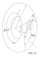
- Figure 2 illustrates line 3 which illustrates a belt having a true geodesic line. Note that the cord is tangent to the belt edge at point A.
- Figures 3a and 3b each illustrate a front view of a tire on a belt making machine constructed with a modified geodesic belt 120, 130 of the present invention.
- the angle of the belt at the edges is slightly less than 180 degrees.
- Each belt looks different due to the selection of different parameters such as desired centerline angle ⁇ s.
- the geodesic belt is applied using a belt applier on a rotating B&T drum.
- the belt applier utilizes a mechanical arm applier (not shown) that translates in an axial direction from one belt edge shoulder to the other belt edge shoulder.
- a computer controller controls the arm position (x axis) coordinated with the speed of the B&T drum ( ⁇ ).
- the modified geodesic belt path 120, 130 is determined from the following steps.
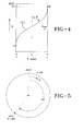
- Figures 4 and 7 illustrate a modified geodesic path 151 according to the teachings of the invention.
- the modified geodesic path of the invention deviates from an angle of zero at the belt edges in order to avoid excessive build up at the belt edges.
- the modified geodesic path also deviates from the angle at the centerline, so that a desired centerline angle ⁇ s may be obtained.
- a desired centerline angle ⁇ s may be obtained.
- a geoline is formed in 0.45 revolutions for a true geodesic path.
- a geoline is defined as the three dimensional minimum path from one belt edge (point A on Figure 4 ) to the opposite belt edge (point D, Figure 4 ).
- a belt would require multiple geolines in order to completely cover the tire belt surface, typically 80 geolines.
- AG is defined as the change in angle ⁇ from the starting point A to the ending point D of the geoline as shown in Figure 5 .
- AG is set to have an initial value by specifying an initial NR value of 20, and an NG value of 30.
- the value of NG, AG will change as the iterative series of calculations are performed.
- AG 360 * NR / NG ,
- Figure 6 illustrates the flow chart for outlining the steps to calculate a modified geoline for a belt.
- the belt width, strip width and desired centerline angle ⁇ s are input.
- ⁇ s is set to the input value ⁇ s
- NR is set to 20
- NG is set to 30.
- the remaining geolines for the set are determined using equations from step 40.
- the other remaining geolines can be determined by adding AG to the Psi values of the geoline data set.
- the first set of data points describing the minimal path are known in X, Y, ⁇ coordinates.
- several sets are needed, typically in the range of 2 to 5 sets. Assume in this example four data sets are needed.
- the value K is computed from the equation below.
- the first data set is preferably modified by a factor K in order to completely cover the belt area by the cords and to ensure that the second data set begins where the first data set ends.
- Set two will start at 90 degrees and end at 180 degrees.
- Set three will start at 180 degrees and end at 270 degrees.
- Set four will start at 270 degrees and end at 0/360 degrees.
- K 360 * NR + 360 / NS ) / NR
- NS is number of data sets to be generated, in the example 4.
- K is a multiplier which slightly stretches the data set to end precisely at an even interval such as 90 degrees.
- the cord may comprise one or more rubber coated cords which may be polyester, nylon, rayon, steel, flexten or aramid.
Landscapes
- Engineering & Computer Science (AREA)
- Mechanical Engineering (AREA)
- Tires In General (AREA)
Abstract
Description
- The invention is directed to the field of tire manufacturing and tire construction and in particular to a tire having a geodesic belt and to a method of manufacturing a geodesic belt.
- It is known in the art to utilize zigzag belts in aircraft tires and truck tires. Zigzag belts are typically continuously woven from one belt edge to the other belt edge at a constant angle, with a turn around at the belt edges. A zigzag belt results in two layers of cord interwoven together with no cut belt edges. However, depending upon the tire size and other factors, the angle of the zigzag belt in the crown area is typically 10-14 degrees, with the turnaround angle at the belt edges typically around 90 degrees. It is however desired to have a higher angle at the centerline in order to improve wear, typically in the range of 15-45 degrees.
- A geodesic belt construction has the belt cords arranged on a geodesic line on the tire's curved surface. On a curved surface the geodesic path is the least curvature or shortest distance between two points on a curved surface. A true geodesic path follows the special mathematical law: ρ cosα = constant. A true geodesic belt has the advantage of a higher crown angle at the centerline as compared to the zigzag belt. The true geodesic belt also has the advantage of no shear stress, because it is the minimum path. Unlike the zigzag belt construction, the geodesic belt angle continuously varies such that the angle is high at the centerline, typically around 45 degrees, and is 180 degrees at the belt edges. Both the zigzag belt and the geodesic belt have an issue at the belt edges of accumulation. It is thus desired to provide an improved belt design which modifies the geodesic path to overcome the disadvantages of the geodesic belt. Thus for the foregoing reasons, it is desired to provide an tire having a belt with a modified geodesic path without the above described disadvantages.
- The invention relates to a pneumatic tire in accordance with
claim 1 and to a method of forming a geodesic belt structure for use in such a tire in accordance withclaim 13. - Dependent claims refer to preferred embodiments of the invention.
- In one aspect of the invention, a pneumatic tire having a carcass and a belt structure is disclosed, the belt structure comprising first belt layer having cords arranged at an angle of 5 degrees or less with respect to the midcircumferential plane of the tire and a geodesic belt structure, wherein the geodesic belt structure is formed in a three dimensional path extending in alternation to turnaround points at each lateral edge of the geodesic belt structure, and wherein the geodesic belt structure is wider than the first belt layer and is located radially outward of the first belt layer.
- In another aspect of the invention, a method of forming a geodesic belt structure for a tire is disclosed. The method comprises the steps of: a) selecting a desired centerline angle θs; b) calculating a three dimensional minimal distance path L from one belt edge (-W/2) to the other belt structure edge (W/2) and from ψ=0 to ψ=AG, where AG=NR/NG, where NR is the number of revolutions to form NG geolines, and where NG is the number of geolines in a set; c) calculating a centerline angle θ; d) modifying the angle ψ if θ is not within a predetermined range of θs; and e) repeating steps b through d until θ is within the predetermined range of θs.
- In one aspect of the invention, the tire may further comprise a third belt layer located radially outward of the first belt layer or located radially outward of the first belt layer and the second belt layer.
- In yet another aspect of the invention, the third belt layer is preferably axially wider than the first belt layer or is preferably axially wider than the first belt layer and the second belt.
- In yet another aspect of the invention, the tire may further comprise a fourth belt layer located radially outward of the third belt layer. The fourth belt layer is preferably axially wider than the third belt layer.
- In yet another aspect of the invention, the tire may comprise a first geodesic belt structure and a second geodesic belt structure wherein the first geodesic belt structure is axially wider than the second geodesic belt structure and/or wherein the first geodesic belt structure is located radially adjacent to the second geodesic belt structure.
- In yet another aspect of the invention, one or more of the carcass plies may comprise cords made of nylon.
- In yet another aspect of the invention, the angle at the centerline of the geodesic belt may be modified and the three dimensional minimal distance path L from one belt edge to the other belt edge may be calculated using the following equation: L= Σ(SQRT(X2 +Y2+Z2)), for ψ = 0 to AG, where Z =R*δψ.
- In yet another aspect of the invention, the method of forming a geodesic belt structure may include: If θ equals θs +/-Δ, then determining a factor K=[360*NR+360/NS])/NR.
- In yet another aspect of the invention, in the method of forming a geodesic belt structure, all the ψ data points may be multiplied by factor k, ψ' = k*ψ.
- In another aspect of the invention, a method of forming a geodesic belt for a tire is disclosed, the method comprising the steps of: selecting a desired centerline angle θs, calculating a three dimensional minimal distance path L from one belt edge to the other belt edge using the following equation:
- a. L= Σ(SQRT(X2 +Y2+Z2)), for ψ = 0 to AG, where Z =R*δψ;
- b. calculating θ at centerline of path;
- c. determining a data set of points of the minimum path;
- d. incrementing NG if θ ≠ θs and then calculating a new AG=NR/NG;
- e. repeating steps b through d until θ equals θs +/-Δ.
- "Axial" and "axially" means the lines or directions that are parallel to the axis of rotation of the tire.
- "Radial" and "radially" mean directions radially toward or away from the axis of rotation of the tire.
- The invention will be described by way of example and with reference to the accompanying drawings in which:
-
Figure 1 is a cross-sectional view of one half of a symmetrical aircraft tire; -
Figure 2 is a perspective view of a tire illustrating an idealgeodesic line 3 on the outer surface; -
Figures 3a ,3b are front views of a tire with a modified geodesic belt; -
Figure 4 is a schematic view of a modified geoline from ψ=0 to ψ=360 degrees; -
Figure 5 is a side view simplified schematic of a tire building drum illustrating angle of drum rotation: ψ=0 to ψ=AG; -
Figure 6 is a process flow chart showing method steps of the invention; -
Figure 7 illustrates the minimum path L in rectangular coordinates; and -
Figure 8 is a cross-sectional view of one half of a symmetrical belt package. -
Figure 1 illustrates a cross-sectional view of one half of aradial aircraft tire 11 of the present invention. The tire is symmetrical about the mid-circumferential plane so that only one half is illustrated. As shown, theaircraft tire 11 comprises a pair ofbead portions 110 each containing abead core 12 embedded therein. One example of a bead core suitable for use in an aircraft tire is shown inUS-B-6,571,847 . Thebead core 12 preferably has an aluminum, aluminum alloy or other light weight alloy in the center portion surrounded by a plurality of steel sheath wires (not shown). A person skilled in the art may appreciate that other bead cores may also be utilized. The invention may also used with tires other than aircraft tires. - The aircraft tire further comprises a
sidewall portion 116 extending substantially outward from each of thebead portions 110 in the radial direction of the tire, and atread portion 13 extending between the radially outer ends of thesidewall portions 116. Furthermore, thetire 11 is reinforced with acarcass 22 toroidally extending from one of thebead portions 110 to theother bead portion 110. The carcass comprises one or moreinner carcass plies 22 and one or moreouter carcass plies 24, preferably oriented in the radial direction. Among these carcass plies 22, 24, typically fourinner plies 22 are wound around thebead core 12 from inside of the tire toward outside thereof to form turnup portions, while typically twoouter plies 24 are extended downward to thebead core 12 along the outside of the turnup portion of theinner carcass ply 22. Each of these carcass plies 22, 24 may comprise any suitable cord, typically nylon cords such as nylon-6,6 cords extending substantially perpendicular to an equatorial plane EP of the tire (i.e., extending in the radial direction of the tire). Preferably the nylon cords have an 1890 denier/2/2 or 1890 denier/3 construction. One or more of the carcass plies 22, 24 may also comprise an aramid and nylon cord structure, for example, a hybrid cord, a high energy cord or a merged cord. Examples of suitable cords are described inUS-A-4,893,665 ,US-A-4,155,394 orUS-A-6,799,618 . - The
aircraft tire 11 further comprises a belt package orbelt structure 150 arranged between thecarcass 22 and thetread rubber 13.Figure 8 illustrates a first embodiment of one half of abelt package 150 suitable for use in the aircraft tire. Thebelt package 150 is symmetrical about the mid-circumferential plane so that only one half of the belt package is illustrated. Thebelt package 150 as shown comprises afirst belt layer 51 located adjacent the carcass. Thefirst belt layer 51 is preferably formed of cords having an angle of 5 degrees or less with respect to the midcircumferential plane. Preferably, thefirst belt layer 51 is formed of a rubberized strip of two or more cords made by spirally or helically winding the cords at an angle of plus or minus 5 degrees or less relative to the circumferential direction. Thefirst belt layer 51 is preferably the narrowest belt structure of thebelt package 150 and has preferably a width in the range of from 13% to 100% of the rim width (width between flanges), and more preferably in the range of from 20% to 70% of the rim width (width between flanges), and most preferably in the range of from 30% to 42% of the rim width (width between flanges). - The
belt package 150 further comprises asecond belt layer 61 located radially outward of thefirst belt layer 51. Thesecond belt layer 61 is preferably formed of cords having an angle of 5 degrees or less with respect to the mid-circumferential plane. Preferably, thesecond belt layer 61 is formed of a rubberized strip of two or more cords made by spirally or helically winding the cords at an angle of plus or minus 5 degrees or less relative to the circumferential direction. Thefirst belt 51 is the radially innermost belt. Thefirst belt 51 is preferably the narrowest belt of all the belts. Thesecond belt 61 is located radially outward of the first belt, and has preferably a slightly larger width than thefirst belt 51. The embodiment optionally further includes a third 71 andfourth belt 81 preferably having a low angle of 5 degrees or less with respect to the circumferential plane. The third andfourth belts third belt 71 is located radially outward of thesecond belt 61, and is preferably substantially wider than the first andsecond belts third belt 71 is preferably the widest belt of the first, second andfourth belts fourth belt 81 is located radially outward of thethird belt 71, and is preferably the widest of thelow angle belts fourth belt 81 has a width slightly less than thethird belt 71. The embodiment further includes a first 120 and second 130 geodesic belt structure that are both located radially outward of the first through fourth belts. The firstgeodesic belt structure 120 is preferably located radially outward of thefourth belt 81 and preferably has the widest width GW1 all of thebelts - (1) 0.3 < BWs/BWg < 0.6, and more preferably in the range of 0.3< BWs/BWg < 0.5
- In the above embodiment, it is additionally preferred that the ply be made of nylon and that the
belt structure 150 be made of an aramid/nylon blend, such that the ply cord % elongation is greater than the belt cord % elongation at break. It is additionally preferred that the maximum belt cord elongation at break be less than 18%. - The
belt package 150 has at least onegeodesic belt Figure 2 illustratesline 3 which illustrates a belt having a true geodesic line. Note that the cord is tangent to the belt edge at point A. A true geodesic ply pattern follows the mathematical equation exactly: ρ cos α = ρ0 cos α0, wherein ρ is the radial distance from the axis of rotation to the cord at a given location; α is the angle of the cord at a given location with respect to the midcircumferential plane; and ρ is the radial distance from the axis of rotation of the core to the crown, and ρ0, α0 is the radius and angle at the midcircumferential plane. -
Figures 3a and3b each illustrate a front view of a tire on a belt making machine constructed with a modifiedgeodesic belt geodesic belt path -
Figures 4 and7 illustrate a modifiedgeodesic path 151 according to the teachings of the invention.Figure 4 illustrates the path for 1 revolution from 0 degrees to Psi=360 degrees. For a true geodesic path, at each belt edge (W/2) the angle α = 0 degrees so that the cord is tangent at the belt edge. The modified geodesic path of the invention deviates from an angle of zero at the belt edges in order to avoid excessive build up at the belt edges. The modified geodesic path also deviates from the angle at the centerline, so that a desired centerline angle θs may be obtained. For purposes of illustration, for an exemplary tire size, it is known that there are 20 geolines formed in 9 revolutions. Thus a geoline is formed in 0.45 revolutions for a true geodesic path. At each belt edge, the geoline is tangent to the belt edges (α =0), and the belt angle at the centerline is about 15.5 degrees. A geoline is defined as the three dimensional minimum path from one belt edge (point A onFigure 4 ) to the opposite belt edge (point D,Figure 4 ). Thus a belt would require multiple geolines in order to completely cover the tire belt surface, typically 80 geolines. - AG is defined as the change in angle ψ from the starting point A to the ending point D of the geoline as shown in
Figure 5 . AG is set to have an initial value by specifying an initial NR value of 20, and an NG value of 30. The value of NG, AG will change as the iterative series of calculations are performed.
- Where NR = number of revolutions to form NG geolines
- NG=number of geolines in the set, all sets are equal
-
Figure 6 illustrates the flow chart for outlining the steps to calculate a modified geoline for a belt. Forstep 10, the belt width, strip width and desired centerline angle θs are input. Forstep 20, θs is set to the input value θs, and NR is set to 20, NG is set to 30. These values were determined from experience. - NR = number of revolutions in one set of geolines
- NG=number of geolines in a set that have a starting point and ending point of zero degrees Psi
- For
step 30, AG is determined from the following calculation:
- In
step 40, the three dimensional minimum distance path L is determined for a geoline from the equation below, over the range from, X= -W/2 to W/2, Psi=0 to AG
- In
step 50, the angle θ is calculated at the centerline and compared with the input value θs. Forstep 60, if θ = θs is not true, then step 70 is performed wherein NG is increased by the following formula:
- Steps 30-70 are repeated until θ = θs.
- Once θ = θs, then the remaining geolines for the set are determined using equations from
step 40. Alternatively, once a geoline is calculated, the other remaining geolines can be determined by adding AG to the Psi values of the geoline data set. - A first data set is now known, wherein NR=20, and NG=70 was determined in this example. The first set of data points describing the minimal path are known in X, Y, Ψ coordinates. In order to fill the belt surface sufficiently, several sets are needed, typically in the range of 2 to 5 sets. Assume in this example four data sets are needed. In order to determine the starting point of sets two through four, the value K is computed from the equation below.
- For four data sets, the first data set is preferably modified by a factor K in order to completely cover the belt area by the cords and to ensure that the second data set begins where the first data set ends. For four specified data sets, the ending point of the first data set will occur precisely at Ψ=90 degrees. Thus our first data set will start at Psi=0 and end at Psi=90 degrees. Set two will start at 90 degrees and end at 180 degrees. Set three will start at 180 degrees and end at 270 degrees. Set four will start at 270 degrees and end at 0/360 degrees.

- NS is number of data sets to be generated, in the example 4.
- In order to fill the belt, it is desired to have at least 4 data sets generated.
- For the first data set, Ψ'=K* Ψ
- Thus, the first data set has 70 geolines formed in 20 revolutions, wherein the data set begins at Ψ=0 and ends at Ψ=90. K is a multiplier which slightly stretches the data set to end precisely at an even interval such as 90 degrees. The second data set begins at Ψ=90 and ends at Ψ=180. This data set can be derived from the first data set by adding Ψ= Ψ + 90, while the other data values stay the same. The third data set begins at Ψ= 180 and ends at Ψ=270 degrees. This data set can be derived from the first data set by adding Ψ= Ψ + 180, while the other data values stay the same. The fourth data set begins at Ψ=270 degrees and ends at Ψ=360 degrees. This data set can be derived from the first data set by adding Ψ= Ψ + 270, while the other data values stay the same.
- The cord may comprise one or more rubber coated cords which may be polyester, nylon, rayon, steel, flexten or aramid.
Claims (15)
- A pneumatic tire having a carcass (22, 24) and a belt structure (150), the belt structure (150) comprising first belt layer (51) having cords arranged at an angle of 5 degrees or less with respect to the midcircumferential plane of the tire (11) and a geodesic belt structure (120, 130), wherein the geodesic belt structure (120, 130) is formed in a three dimensional path (151) extending in alternation to turnaround points (A, B) at each lateral edge (-W/2, W/2) of the geodesic belt structure (120, 130), and wherein the geodesic belt structure (120, 130) is wider than the first belt layer (51) and is located radially outward of the first belt layer (51).
- The pneumatic tire of claim 1 having a second belt layer (61) having cords arranged at an angle of 5 degrees or less with respect to the midcircumferential plane of the tire (11).
- The pneumatic tire of claim 2 wherein the second belt layer (61) is axially wider than the first belt layer (51) and/or wherein the second belt layer (61) is radially outward of the first belt layer (51).
- The pneumatic tire of at least one of the previous claims wherein the geodesic belt structure (120, 130) is the axially widest belt layer of the belt structure (150) and/or wherein the geodesic belt structure (120, 130) is the radially outermost belt layer of the belt structure (150).
- The pneumatic tire of at least one of the previous claims wherein the geodesic belt structure (120, 130) has a centerline angle in the range of from 15 to 30 degrees.
- The pneumatic tire of at least one of the previous claims wherein the geodesic belt structure (120, 130) comprises a first geodesic belt structure (120) and a second geodesic belt structure (130), wherein the first geodesic belt structure (120) is located radially inward of the second geodesic belt structure (130).
- The pneumatic tire of at least one of the previous claims wherein the belt structure (150) is formed from a continuous strip.
- The pneumatic tire of at least one of the previous claims wherein the belt structure (150) is formed from a nylon/aramid strip material, a nylon material or an aramid material.
- The pneumatic tire of at least one of the previous claims wherein at least one belt layer (51, 61, 71, 81) has cords having a percent elongation at break less than 24% and a break strength greater than 400N.
- The pneumatic tire of at least one of the previous claims wherein the carcass ply cords have a greater elongation at break than the belt structure cords.
- The pneumatic tire of claim 1 wherein the geodesic belt structure is formed by calculating a three dimensional minimal distance path L from one belt edge to the other belt edge using the equation: L= Σ(SQRT(X2 +Y2+Z2)), for ψ = 0 to AG, where Z =R*δψ.
- The pneumatic tire of at least one of the previous claims wherein the tire (11) is an aircraft tire.
- A method of forming a geodesic belt structure (150) for a tire (11), the method comprising the steps of:a. selecting a desired centerline angle θs;b. calculating a three dimensional minimal distance path L from one belt edge (-W/2) to the other belt structure edge (W/2) and from ψ=0 to ψ=AG, where AG=NR/NG, where NR is the number of revolutions to form NG geolines, and where NG is the number of geolines in a set;c. calculating a centerline angle θ;d. modifying the angle ψ if θ is not within a predetermined range of θs; ande. repeating steps b through d until θ is within the predetermined range of θs.
- The method of claim 13 wherein a data set of X, Y, Rψ is determined from the minimal distance path L.
- The method of claim 13 or 14 wherein the three dimensional minimal distance path L from one belt edge to the other belt edge is determined using the following equation: L= Σ(SQRT(X2 +Y2+Z2)), for ψ = 0 to AG, where Z =R*δψ.
Applications Claiming Priority (4)
| Application Number | Priority Date | Filing Date | Title |
|---|---|---|---|
| US201261739933P | 2012-12-20 | 2012-12-20 | |
| US201261740204P | 2012-12-20 | 2012-12-20 | |
| US13/775,637 US20140180652A1 (en) | 2012-12-20 | 2013-02-25 | Method for constructing a modified geodesic belt |
| US13/793,104 US9199512B2 (en) | 2012-12-20 | 2013-03-11 | Pneumatic tire with geodesic belt |
Publications (2)
| Publication Number | Publication Date |
|---|---|
| EP2746065A1 true EP2746065A1 (en) | 2014-06-25 |
| EP2746065B1 EP2746065B1 (en) | 2016-08-03 |
Family
ID=49884940
Family Applications (1)
| Application Number | Title | Priority Date | Filing Date |
|---|---|---|---|
| EP13197331.5A Not-in-force EP2746065B1 (en) | 2012-12-20 | 2013-12-16 | Pneumatic tire with geodesic belt |
Country Status (1)
| Country | Link |
|---|---|
| EP (1) | EP2746065B1 (en) |
Cited By (1)
| Publication number | Priority date | Publication date | Assignee | Title |
|---|---|---|---|---|
| JP2021079943A (en) * | 2019-11-19 | 2021-05-27 | ザ・グッドイヤー・タイヤ・アンド・ラバー・カンパニー | Aircraft tire with reduced weight |
Citations (6)
| Publication number | Priority date | Publication date | Assignee | Title |
|---|---|---|---|---|
| GB810425A (en) * | 1955-08-11 | 1959-03-18 | Dunlop Rubber Co | Pneumatic tyres |
| US3024828A (en) * | 1954-06-29 | 1962-03-13 | Dunlop Tire & Rubber Corp | Pneumatic tires |
| US4155394A (en) | 1977-08-29 | 1979-05-22 | The Goodyear Tire & Rubber Company | Tire cord composite and pneumatic tire |
| US4893665A (en) | 1988-02-17 | 1990-01-16 | The Goodyear Tire & Rubber Company | Cables for reinforcing deformable articles and articles reinforced by said cables |
| US6571847B1 (en) | 2002-01-24 | 2003-06-03 | The Goodyear Tire & Rubber Company | Light weight alloy bead core |
| US6799618B2 (en) | 2002-12-18 | 2004-10-05 | The Goodyear Tire & Rubber Company | Pneumatic tire having an overlay reinforcement |
-
2013
- 2013-12-16 EP EP13197331.5A patent/EP2746065B1/en not_active Not-in-force
Patent Citations (6)
| Publication number | Priority date | Publication date | Assignee | Title |
|---|---|---|---|---|
| US3024828A (en) * | 1954-06-29 | 1962-03-13 | Dunlop Tire & Rubber Corp | Pneumatic tires |
| GB810425A (en) * | 1955-08-11 | 1959-03-18 | Dunlop Rubber Co | Pneumatic tyres |
| US4155394A (en) | 1977-08-29 | 1979-05-22 | The Goodyear Tire & Rubber Company | Tire cord composite and pneumatic tire |
| US4893665A (en) | 1988-02-17 | 1990-01-16 | The Goodyear Tire & Rubber Company | Cables for reinforcing deformable articles and articles reinforced by said cables |
| US6571847B1 (en) | 2002-01-24 | 2003-06-03 | The Goodyear Tire & Rubber Company | Light weight alloy bead core |
| US6799618B2 (en) | 2002-12-18 | 2004-10-05 | The Goodyear Tire & Rubber Company | Pneumatic tire having an overlay reinforcement |
Cited By (1)
| Publication number | Priority date | Publication date | Assignee | Title |
|---|---|---|---|---|
| JP2021079943A (en) * | 2019-11-19 | 2021-05-27 | ザ・グッドイヤー・タイヤ・アンド・ラバー・カンパニー | Aircraft tire with reduced weight |
Also Published As
| Publication number | Publication date |
|---|---|
| EP2746065B1 (en) | 2016-08-03 |
Similar Documents
| Publication | Publication Date | Title |
|---|---|---|
| EP2394822B1 (en) | Tire comprising a zigzag belt reinforcing structure, in particular a reduced weight aircraft tire | |
| EP2199105B1 (en) | A method of making a pneumatic tire | |
| US20240051344A1 (en) | Reduced weight aircraft tire | |
| EP2420396B1 (en) | Pneumatic tire | |
| US11186122B2 (en) | Reduced weight aircraft tire | |
| US20160200147A1 (en) | Reduced weight aircraft tire | |
| EP2202095B1 (en) | Pneumatic tire | |
| EP2199106A1 (en) | Pneumatic tire | |
| EP3290232B1 (en) | Tire with low weight and high burst strength | |
| EP2977229B1 (en) | Reduced weight aircraft tire | |
| US9199512B2 (en) | Pneumatic tire with geodesic belt | |
| CN103879233B (en) | The pneumatic tire with beam with geodesic line | |
| EP2199107A1 (en) | Pneumatic tire | |
| EP2455233B1 (en) | Pneumatic tire comprising a zigzag belt structure | |
| EP2746065B1 (en) | Pneumatic tire with geodesic belt | |
| EP2199108A1 (en) | Pneumatic tire | |
| GB2495167A (en) | Pneumatic tyre | |
| US20140180652A1 (en) | Method for constructing a modified geodesic belt | |
| GB2507198A (en) | Pneumatic tyre |
Legal Events
| Date | Code | Title | Description |
|---|---|---|---|
| PUAI | Public reference made under article 153(3) epc to a published international application that has entered the european phase |
Free format text: ORIGINAL CODE: 0009012 |
|
| 17P | Request for examination filed |
Effective date: 20131216 |
|
| AK | Designated contracting states |
Kind code of ref document: A1 Designated state(s): AL AT BE BG CH CY CZ DE DK EE ES FI FR GB GR HR HU IE IS IT LI LT LU LV MC MK MT NL NO PL PT RO RS SE SI SK SM TR |
|
| AX | Request for extension of the european patent |
Extension state: BA ME |
|
| R17P | Request for examination filed (corrected) |
Effective date: 20150105 |
|
| RBV | Designated contracting states (corrected) |
Designated state(s): AL AT BE BG CH CY CZ DE DK EE ES FI FR GB GR HR HU IE IS IT LI LT LU LV MC MK MT NL NO PL PT RO RS SE SI SK SM TR |
|
| RIC1 | Information provided on ipc code assigned before grant |
Ipc: B60C 9/26 20060101AFI20160216BHEP |
|
| GRAP | Despatch of communication of intention to grant a patent |
Free format text: ORIGINAL CODE: EPIDOSNIGR1 |
|
| INTG | Intention to grant announced |
Effective date: 20160329 |
|
| GRAS | Grant fee paid |
Free format text: ORIGINAL CODE: EPIDOSNIGR3 |
|
| GRAA | (expected) grant |
Free format text: ORIGINAL CODE: 0009210 |
|
| AK | Designated contracting states |
Kind code of ref document: B1 Designated state(s): AL AT BE BG CH CY CZ DE DK EE ES FI FR GB GR HR HU IE IS IT LI LT LU LV MC MK MT NL NO PL PT RO RS SE SI SK SM TR |
|
| REG | Reference to a national code |
Ref country code: GB Ref legal event code: FG4D |
|
| REG | Reference to a national code |
Ref country code: CH Ref legal event code: EP Ref country code: AT Ref legal event code: REF Ref document number: 817074 Country of ref document: AT Kind code of ref document: T Effective date: 20160815 |
|
| REG | Reference to a national code |
Ref country code: IE Ref legal event code: FG4D |
|
| REG | Reference to a national code |
Ref country code: DE Ref legal event code: R096 Ref document number: 602013010031 Country of ref document: DE |
|
| REG | Reference to a national code |
Ref country code: FR Ref legal event code: PLFP Year of fee payment: 4 |
|
| REG | Reference to a national code |
Ref country code: NL Ref legal event code: MP Effective date: 20160803 |
|
| REG | Reference to a national code |
Ref country code: LT Ref legal event code: MG4D |
|
| REG | Reference to a national code |
Ref country code: AT Ref legal event code: MK05 Ref document number: 817074 Country of ref document: AT Kind code of ref document: T Effective date: 20160803 |
|
| PG25 | Lapsed in a contracting state [announced via postgrant information from national office to epo] |
Ref country code: NO Free format text: LAPSE BECAUSE OF FAILURE TO SUBMIT A TRANSLATION OF THE DESCRIPTION OR TO PAY THE FEE WITHIN THE PRESCRIBED TIME-LIMIT Effective date: 20161103 Ref country code: RS Free format text: LAPSE BECAUSE OF FAILURE TO SUBMIT A TRANSLATION OF THE DESCRIPTION OR TO PAY THE FEE WITHIN THE PRESCRIBED TIME-LIMIT Effective date: 20160803 Ref country code: FI Free format text: LAPSE BECAUSE OF FAILURE TO SUBMIT A TRANSLATION OF THE DESCRIPTION OR TO PAY THE FEE WITHIN THE PRESCRIBED TIME-LIMIT Effective date: 20160803 Ref country code: HR Free format text: LAPSE BECAUSE OF FAILURE TO SUBMIT A TRANSLATION OF THE DESCRIPTION OR TO PAY THE FEE WITHIN THE PRESCRIBED TIME-LIMIT Effective date: 20160803 Ref country code: IS Free format text: LAPSE BECAUSE OF FAILURE TO SUBMIT A TRANSLATION OF THE DESCRIPTION OR TO PAY THE FEE WITHIN THE PRESCRIBED TIME-LIMIT Effective date: 20161203 Ref country code: NL Free format text: LAPSE BECAUSE OF FAILURE TO SUBMIT A TRANSLATION OF THE DESCRIPTION OR TO PAY THE FEE WITHIN THE PRESCRIBED TIME-LIMIT Effective date: 20160803 Ref country code: LT Free format text: LAPSE BECAUSE OF FAILURE TO SUBMIT A TRANSLATION OF THE DESCRIPTION OR TO PAY THE FEE WITHIN THE PRESCRIBED TIME-LIMIT Effective date: 20160803 |
|
| PG25 | Lapsed in a contracting state [announced via postgrant information from national office to epo] |
Ref country code: SE Free format text: LAPSE BECAUSE OF FAILURE TO SUBMIT A TRANSLATION OF THE DESCRIPTION OR TO PAY THE FEE WITHIN THE PRESCRIBED TIME-LIMIT Effective date: 20160803 Ref country code: PL Free format text: LAPSE BECAUSE OF FAILURE TO SUBMIT A TRANSLATION OF THE DESCRIPTION OR TO PAY THE FEE WITHIN THE PRESCRIBED TIME-LIMIT Effective date: 20160803 Ref country code: GR Free format text: LAPSE BECAUSE OF FAILURE TO SUBMIT A TRANSLATION OF THE DESCRIPTION OR TO PAY THE FEE WITHIN THE PRESCRIBED TIME-LIMIT Effective date: 20161104 Ref country code: LV Free format text: LAPSE BECAUSE OF FAILURE TO SUBMIT A TRANSLATION OF THE DESCRIPTION OR TO PAY THE FEE WITHIN THE PRESCRIBED TIME-LIMIT Effective date: 20160803 Ref country code: AT Free format text: LAPSE BECAUSE OF FAILURE TO SUBMIT A TRANSLATION OF THE DESCRIPTION OR TO PAY THE FEE WITHIN THE PRESCRIBED TIME-LIMIT Effective date: 20160803 Ref country code: ES Free format text: LAPSE BECAUSE OF FAILURE TO SUBMIT A TRANSLATION OF THE DESCRIPTION OR TO PAY THE FEE WITHIN THE PRESCRIBED TIME-LIMIT Effective date: 20160803 Ref country code: PT Free format text: LAPSE BECAUSE OF FAILURE TO SUBMIT A TRANSLATION OF THE DESCRIPTION OR TO PAY THE FEE WITHIN THE PRESCRIBED TIME-LIMIT Effective date: 20161205 |
|
| PG25 | Lapsed in a contracting state [announced via postgrant information from national office to epo] |
Ref country code: RO Free format text: LAPSE BECAUSE OF FAILURE TO SUBMIT A TRANSLATION OF THE DESCRIPTION OR TO PAY THE FEE WITHIN THE PRESCRIBED TIME-LIMIT Effective date: 20160803 Ref country code: EE Free format text: LAPSE BECAUSE OF FAILURE TO SUBMIT A TRANSLATION OF THE DESCRIPTION OR TO PAY THE FEE WITHIN THE PRESCRIBED TIME-LIMIT Effective date: 20160803 |
|
| REG | Reference to a national code |
Ref country code: DE Ref legal event code: R097 Ref document number: 602013010031 Country of ref document: DE |
|
| PG25 | Lapsed in a contracting state [announced via postgrant information from national office to epo] |
Ref country code: CZ Free format text: LAPSE BECAUSE OF FAILURE TO SUBMIT A TRANSLATION OF THE DESCRIPTION OR TO PAY THE FEE WITHIN THE PRESCRIBED TIME-LIMIT Effective date: 20160803 Ref country code: BE Free format text: LAPSE BECAUSE OF FAILURE TO SUBMIT A TRANSLATION OF THE DESCRIPTION OR TO PAY THE FEE WITHIN THE PRESCRIBED TIME-LIMIT Effective date: 20160803 Ref country code: SM Free format text: LAPSE BECAUSE OF FAILURE TO SUBMIT A TRANSLATION OF THE DESCRIPTION OR TO PAY THE FEE WITHIN THE PRESCRIBED TIME-LIMIT Effective date: 20160803 Ref country code: BG Free format text: LAPSE BECAUSE OF FAILURE TO SUBMIT A TRANSLATION OF THE DESCRIPTION OR TO PAY THE FEE WITHIN THE PRESCRIBED TIME-LIMIT Effective date: 20161103 Ref country code: SK Free format text: LAPSE BECAUSE OF FAILURE TO SUBMIT A TRANSLATION OF THE DESCRIPTION OR TO PAY THE FEE WITHIN THE PRESCRIBED TIME-LIMIT Effective date: 20160803 Ref country code: DK Free format text: LAPSE BECAUSE OF FAILURE TO SUBMIT A TRANSLATION OF THE DESCRIPTION OR TO PAY THE FEE WITHIN THE PRESCRIBED TIME-LIMIT Effective date: 20160803 |
|
| PLBE | No opposition filed within time limit |
Free format text: ORIGINAL CODE: 0009261 |
|
| STAA | Information on the status of an ep patent application or granted ep patent |
Free format text: STATUS: NO OPPOSITION FILED WITHIN TIME LIMIT |
|
| 26N | No opposition filed |
Effective date: 20170504 |
|
| REG | Reference to a national code |
Ref country code: CH Ref legal event code: PL |
|
| PG25 | Lapsed in a contracting state [announced via postgrant information from national office to epo] |
Ref country code: SI Free format text: LAPSE BECAUSE OF FAILURE TO SUBMIT A TRANSLATION OF THE DESCRIPTION OR TO PAY THE FEE WITHIN THE PRESCRIBED TIME-LIMIT Effective date: 20160803 |
|
| PG25 | Lapsed in a contracting state [announced via postgrant information from national office to epo] |
Ref country code: MC Free format text: LAPSE BECAUSE OF FAILURE TO SUBMIT A TRANSLATION OF THE DESCRIPTION OR TO PAY THE FEE WITHIN THE PRESCRIBED TIME-LIMIT Effective date: 20160803 |
|
| REG | Reference to a national code |
Ref country code: IE Ref legal event code: MM4A |
|
| PG25 | Lapsed in a contracting state [announced via postgrant information from national office to epo] |
Ref country code: LI Free format text: LAPSE BECAUSE OF NON-PAYMENT OF DUE FEES Effective date: 20161231 Ref country code: CH Free format text: LAPSE BECAUSE OF NON-PAYMENT OF DUE FEES Effective date: 20161231 Ref country code: LU Free format text: LAPSE BECAUSE OF NON-PAYMENT OF DUE FEES Effective date: 20161216 |
|
| REG | Reference to a national code |
Ref country code: FR Ref legal event code: PLFP Year of fee payment: 5 |
|
| PG25 | Lapsed in a contracting state [announced via postgrant information from national office to epo] |
Ref country code: IE Free format text: LAPSE BECAUSE OF NON-PAYMENT OF DUE FEES Effective date: 20161216 |
|
| PG25 | Lapsed in a contracting state [announced via postgrant information from national office to epo] |
Ref country code: HU Free format text: LAPSE BECAUSE OF FAILURE TO SUBMIT A TRANSLATION OF THE DESCRIPTION OR TO PAY THE FEE WITHIN THE PRESCRIBED TIME-LIMIT; INVALID AB INITIO Effective date: 20131216 |
|
| PG25 | Lapsed in a contracting state [announced via postgrant information from national office to epo] |
Ref country code: CY Free format text: LAPSE BECAUSE OF FAILURE TO SUBMIT A TRANSLATION OF THE DESCRIPTION OR TO PAY THE FEE WITHIN THE PRESCRIBED TIME-LIMIT Effective date: 20160803 Ref country code: MK Free format text: LAPSE BECAUSE OF FAILURE TO SUBMIT A TRANSLATION OF THE DESCRIPTION OR TO PAY THE FEE WITHIN THE PRESCRIBED TIME-LIMIT Effective date: 20160803 |
|
| PG25 | Lapsed in a contracting state [announced via postgrant information from national office to epo] |
Ref country code: MT Free format text: LAPSE BECAUSE OF NON-PAYMENT OF DUE FEES Effective date: 20161216 |
|
| PG25 | Lapsed in a contracting state [announced via postgrant information from national office to epo] |
Ref country code: AL Free format text: LAPSE BECAUSE OF FAILURE TO SUBMIT A TRANSLATION OF THE DESCRIPTION OR TO PAY THE FEE WITHIN THE PRESCRIBED TIME-LIMIT Effective date: 20160803 Ref country code: TR Free format text: LAPSE BECAUSE OF FAILURE TO SUBMIT A TRANSLATION OF THE DESCRIPTION OR TO PAY THE FEE WITHIN THE PRESCRIBED TIME-LIMIT Effective date: 20160803 |
|
| PGFP | Annual fee paid to national office [announced via postgrant information from national office to epo] |
Ref country code: DE Payment date: 20191203 Year of fee payment: 7 |
|
| PGFP | Annual fee paid to national office [announced via postgrant information from national office to epo] |
Ref country code: IT Payment date: 20191209 Year of fee payment: 7 |
|
| PGFP | Annual fee paid to national office [announced via postgrant information from national office to epo] |
Ref country code: GB Payment date: 20191213 Year of fee payment: 7 |
|
| REG | Reference to a national code |
Ref country code: DE Ref legal event code: R119 Ref document number: 602013010031 Country of ref document: DE |
|
| GBPC | Gb: european patent ceased through non-payment of renewal fee |
Effective date: 20201216 |
|
| PG25 | Lapsed in a contracting state [announced via postgrant information from national office to epo] |
Ref country code: IT Free format text: LAPSE BECAUSE OF NON-PAYMENT OF DUE FEES Effective date: 20201216 |
|
| PG25 | Lapsed in a contracting state [announced via postgrant information from national office to epo] |
Ref country code: GB Free format text: LAPSE BECAUSE OF NON-PAYMENT OF DUE FEES Effective date: 20201216 Ref country code: DE Free format text: LAPSE BECAUSE OF NON-PAYMENT OF DUE FEES Effective date: 20210701 |
|
| PGFP | Annual fee paid to national office [announced via postgrant information from national office to epo] |
Ref country code: FR Payment date: 20221010 Year of fee payment: 10 |
|
| PG25 | Lapsed in a contracting state [announced via postgrant information from national office to epo] |
Ref country code: FR Free format text: LAPSE BECAUSE OF NON-PAYMENT OF DUE FEES Effective date: 20231231 |
|
| PG25 | Lapsed in a contracting state [announced via postgrant information from national office to epo] |
Ref country code: FR Free format text: LAPSE BECAUSE OF NON-PAYMENT OF DUE FEES Effective date: 20231231 |