EP2745809A1 - Systems and methods for deploying a portion of a stent using an auger-style device - Google Patents
Systems and methods for deploying a portion of a stent using an auger-style device Download PDFInfo
- Publication number
- EP2745809A1 EP2745809A1 EP13197539.3A EP13197539A EP2745809A1 EP 2745809 A1 EP2745809 A1 EP 2745809A1 EP 13197539 A EP13197539 A EP 13197539A EP 2745809 A1 EP2745809 A1 EP 2745809A1
- Authority
- EP
- European Patent Office
- Prior art keywords
- stent
- cannula
- proximal
- enclosure
- auger
- Prior art date
- Legal status (The legal status is an assumption and is not a legal conclusion. Google has not performed a legal analysis and makes no representation as to the accuracy of the status listed.)
- Granted
Links
Images


Classifications
-
- A—HUMAN NECESSITIES
- A61—MEDICAL OR VETERINARY SCIENCE; HYGIENE
- A61F—FILTERS IMPLANTABLE INTO BLOOD VESSELS; PROSTHESES; DEVICES PROVIDING PATENCY TO, OR PREVENTING COLLAPSING OF, TUBULAR STRUCTURES OF THE BODY, e.g. STENTS; ORTHOPAEDIC, NURSING OR CONTRACEPTIVE DEVICES; FOMENTATION; TREATMENT OR PROTECTION OF EYES OR EARS; BANDAGES, DRESSINGS OR ABSORBENT PADS; FIRST-AID KITS
- A61F2/00—Filters implantable into blood vessels; Prostheses, i.e. artificial substitutes or replacements for parts of the body; Appliances for connecting them with the body; Devices providing patency to, or preventing collapsing of, tubular structures of the body, e.g. stents
- A61F2/82—Devices providing patency to, or preventing collapsing of, tubular structures of the body, e.g. stents
- A61F2/844—Devices providing patency to, or preventing collapsing of, tubular structures of the body, e.g. stents folded prior to deployment
-
- A—HUMAN NECESSITIES
- A61—MEDICAL OR VETERINARY SCIENCE; HYGIENE
- A61F—FILTERS IMPLANTABLE INTO BLOOD VESSELS; PROSTHESES; DEVICES PROVIDING PATENCY TO, OR PREVENTING COLLAPSING OF, TUBULAR STRUCTURES OF THE BODY, e.g. STENTS; ORTHOPAEDIC, NURSING OR CONTRACEPTIVE DEVICES; FOMENTATION; TREATMENT OR PROTECTION OF EYES OR EARS; BANDAGES, DRESSINGS OR ABSORBENT PADS; FIRST-AID KITS
- A61F2/00—Filters implantable into blood vessels; Prostheses, i.e. artificial substitutes or replacements for parts of the body; Appliances for connecting them with the body; Devices providing patency to, or preventing collapsing of, tubular structures of the body, e.g. stents
- A61F2/95—Instruments specially adapted for placement or removal of stents or stent-grafts
-
- A—HUMAN NECESSITIES
- A61—MEDICAL OR VETERINARY SCIENCE; HYGIENE
- A61F—FILTERS IMPLANTABLE INTO BLOOD VESSELS; PROSTHESES; DEVICES PROVIDING PATENCY TO, OR PREVENTING COLLAPSING OF, TUBULAR STRUCTURES OF THE BODY, e.g. STENTS; ORTHOPAEDIC, NURSING OR CONTRACEPTIVE DEVICES; FOMENTATION; TREATMENT OR PROTECTION OF EYES OR EARS; BANDAGES, DRESSINGS OR ABSORBENT PADS; FIRST-AID KITS
- A61F2/00—Filters implantable into blood vessels; Prostheses, i.e. artificial substitutes or replacements for parts of the body; Appliances for connecting them with the body; Devices providing patency to, or preventing collapsing of, tubular structures of the body, e.g. stents
- A61F2/95—Instruments specially adapted for placement or removal of stents or stent-grafts
- A61F2002/9505—Instruments specially adapted for placement or removal of stents or stent-grafts having retaining means other than an outer sleeve, e.g. male-female connector between stent and instrument
-
- A—HUMAN NECESSITIES
- A61—MEDICAL OR VETERINARY SCIENCE; HYGIENE
- A61F—FILTERS IMPLANTABLE INTO BLOOD VESSELS; PROSTHESES; DEVICES PROVIDING PATENCY TO, OR PREVENTING COLLAPSING OF, TUBULAR STRUCTURES OF THE BODY, e.g. STENTS; ORTHOPAEDIC, NURSING OR CONTRACEPTIVE DEVICES; FOMENTATION; TREATMENT OR PROTECTION OF EYES OR EARS; BANDAGES, DRESSINGS OR ABSORBENT PADS; FIRST-AID KITS
- A61F2210/00—Particular material properties of prostheses classified in groups A61F2/00 - A61F2/26 or A61F2/82 or A61F9/00 or A61F11/00 or subgroups thereof
- A61F2210/0014—Particular material properties of prostheses classified in groups A61F2/00 - A61F2/26 or A61F2/82 or A61F9/00 or A61F11/00 or subgroups thereof using shape memory or superelastic materials, e.g. nitinol
Definitions
- the present embodiments relate generally to apparatus and methods for treating medical conditions, and more specifically, to systems and methods for deploying a portion of a stent using an auger-style device.
- Stents may be inserted into an anatomical vessel or duct for various purposes. Stents may maintain or restore patency in a formerly blocked or constricted passageway, for example, following a balloon angioplasty procedure. Other stents may be used for different procedures, for example, stents placed in or about a graft have been used to hold the graft in an open configuration to treat an aneurysm. Additionally, stents coupled to one or both ends of a graft may extend proximally or distally away from the graft to engage a healthy portion of a vessel wall away from a diseased portion of an aneurysm to provide endovascular graft fixation.
- Stents may be either self-expanding or balloon-expandable, or they can have characteristics of both types of stents.
- Self-expanding stents may be delivered to a target site in a compressed configuration and subsequently expanded by removing a delivery sheath, removing trigger wires and/or releasing diameter reducing ties. With self-expanding stents, the stents expand primarily based on their own expansive force without the need for further mechanical expansion.
- the shape-memory alloy may be employed to cause the stent to return to a predetermined configuration upon removal of the sheath or other device maintaining the stent in its pre-deployment configuration.
- the trigger wires When trigger wires are used as a deployment control mechanism, the trigger wires may releasably couple the proximal and/or distal ends of a stent or stent-graft to a delivery catheter.
- one or more trigger wires are looped through a portion of the stent near a vertex of the stent.
- trigger wires may be used to restrain a "Z-stent" or Gianturco stent comprising a series of substantially straight segments interconnected by a series of bent segments. The trigger wires may be disposed through, and pull upon, the bent segments to pull the stent closely against the delivery catheter.
- Trigger wires also may be used in conjunction with different stent designs, such as cannula-cut stents having relatively acute or pointed bends.
- the designs of cannula-cut stents may facilitate compression of the stent to a relatively small delivery profile due to the tight bends of the apices.
- the trigger wires may be looped around one or more vertices formed beneath the proximal and/or distal apices, e.g., a location where an individual apex splits into two separate strut segments.
- trigger wires are threaded through the vertices of such cannula-cut stents, the trigger wires may become crimped at the vertices during compression of the stent to a reduced diameter delivery profile. If the trigger wires are crimped between the strut segments, the trigger wires and/or stent segments may become damaged during delivery, particularly for nickel-titanium stents that may be sensitive to surface imperfections. Furthermore, in some instance, trigger wires may require a relatively high deployment force when being retracted, and the provision of multiple trigger wires may add to the profile of the delivery system.
- the present invention seeks to provide improved deployment of at least a portion of a stent of an implantable medical device. It is to be understood that the teachings herein are applicable to stents and other implantable medical devices including a stent.
- the system comprises a cannula having an outer surface, and an auger having a plurality of turns coupled to the outer surface of the cannula.
- a stent has a portion dimensioned to be disposed within a valley of the auger. Rotation of the cannula and the auger advances the portion of the stent in a predetermined longitudinal direction.
- An enclosure may encircle the auger.
- the enclosure may comprise a plurality of struts separated by a plurality of slots, where the portion of the stent extends through one of the plurality of slots in a delivery state.
- each of the plurality of struts and each of the plurality of slots are generally parallel to each other in a direction running along a longitudinal axis of the apparatus.
- At least one of the plurality of slots of the enclosure has proximal and distal regions and a width at the proximal region is greater than a width at the distal region.
- the stent may comprise a widened securement region that comprises a width that is less than a width of the proximal region of the slot and greater than a width at the distal region of the slot.
- the stent further may comprise a proximal extension disposed adjacent to the widened securement region, where a width of the proximal extension is less than the width of the distal region of the slot.
- the enclosure may be circumferentially rotatable relative to the cannula.
- An atraumatic tip is coupled to the cannula, and at least a portion of the atraumatic tip may be disposed beneath the enclosure.
- a distal stop member coupled to the cannula may be positioned adjacent to a distal end of the enclosure and allows the enclosure to rotate relative to the cannula, but prevents the enclosure from sliding distally over the cannula.
- proximal refers to a direction that is generally closest to the heart during a medical procedure
- distal refers to a direction that is furthest from the heart during a medical procedure
- the apparatus 20 generally comprises a cannula 30 having an outer surface 31, and an auger 40 having a region that is coupled to the outer surface 31 of the cannula 30.
- the cannula 30 may be incorporated as part of a broader stent or stent-graft delivery system, and may span a longitudinal length in which a distal segment extends outside of a patient's body, and a proximal segment, including the auger 40, is delivered towards a target site inside of a patient's body.
- the cannula 30 may be used as an inner cannula, to the extent that one or more outer cannulas or sheaths are disposed coaxially over the cannula 30.
- a stent-graft may be disposed over an exterior surface of the cannula 30 and within one or more outer cannulas or sheaths, thereby encompassing the stent-graft during a delivery stage.
- the cannula 30 may comprise a tubular member having a lumen sized to allow the cannula 30 to be advanced over a wire guide during delivery.
- a proximal region of the cannula 30 may be integrally formed with, or externally coupled to, an atraumatic tip 35.
- the atraumatic tip 35 may comprise proximal and distal regions 36 and 37, respectively, and a central region 38 disposed therebetween.
- the proximal and distal regions 36 and 37 comprise a smaller outer diameter relative to the central region 38, with a first taper allowing for a smooth transition between the proximal region 36 and the central region 38, and a second taper allowing for a smooth transition between the distal region 37 and the central region 38.
- the auger 40 comprises a proximal end 41, a distal end 42, a plurality of helical turns 43 disposed therebetween, and valleys 44 disposed between the helical turns 43, as shown in FIGS. 1-2 . As will be described further below, a portion of a stent 60 may be secured within the valleys 44 between adjacent helical turns 43.
- the auger 40 may be secured directly to the outer surface 31 of the cannula 30 using a suitable mechanism, such as a solder, weld, mechanical attachment, friction fit, or combination of these or other techniques and mechanisms.
- a suitable mechanism such as a solder, weld, mechanical attachment, friction fit, or combination of these or other techniques and mechanisms.
- the auger 40 may be secured to an outer surface of a cylindrical supporting member, such as a steel tube, which in turn is securely disposed around the outer surface 31 of the cannula 30 using any of the aforementioned techniques.
- the exemplary auger 40 may be formed from stainless steel, Nitinol, titanium, or other suitable biocompatible materials.
- the auger 40 is formed from a material that has radiopaque properties.
- the apparatus 20 also comprises an enclosure 70 for housing the auger 40.
- the enclosure 70 comprises a first end 71 having an outer diameter dc 1 , and a second end 72 having a second outer diameter dc 2 , as best seen in FIGS. 1 and 4 .
- the diameter at the first end 71 of the enclosure 70 can be larger to accommodate the provision of the helical turns 43 of the auger 40, while still providing spacing between an outermost surface of the helical turns 43 and an inner surface of the enclosure 70 to ensure that the helical turns 43 can rotate relative to the enclosure 70, as explained further below.
- a second end 72 of the enclosure 70 may be positioned distally of the auger 40, as shown in FIG.
- the second outer diameter dc 2 may be slightly larger than the outer surface 31 of the cannula 30.
- a taper 74 reduces the diameter of the enclosure 70 between the first end having the outer diameter dc 1 and the second end having the reduced outer diameter dc 2 .
- the first end 71 of the enclosure 70 is the proximal end, while the second end 72 of the enclosure 70 is the distal end.
- the axial orientation of the enclosure 70 may be reversed.
- the enclosure 70 may have the first end 71 of greater diameter located distally, while the second end 72 of lesser diameter is located proximally, and a reverse rotational sequence of deployment may be used relative to the manner described herein.
- the enclosure 70 also comprises a plurality of struts separated by a plurality of slots.
- Each of the struts and slots has proximal and distal ends, and are generally parallel to each other in a direction running along a longitudinal axis of the apparatus, as shown in FIG. 1 .
- four struts 75a-75d are depicted as being separated by four slots 76a-76d, as shown in FIGS. 1-2 , 3A-3C and 5 .
- greater or fewer number than four slots and four struts may be provided for coupling selected proximal apices of a stent 60 to the enclosure 70, as explained further below.
- Each of the slots 76a-76d has proximal regions 77 and distal regions 78.
- the proximal regions 77 have a width w 1 , which is greater than a width w 2 of the distal regions 78, as depicted in FIG. 5 .
- the widening of the proximal regions 77 of the slots 76a-76d allows a widened securement region 67 of the stent 60 to be radially advanced only through the proximal regions 77 of their associated slots.
- the widened securement region 67 comprises a width w 3 , which is less than the width w 1 of the proximal regions 77 of the slots, but greater than the width w 2 of the distal regions 78, as indicated by the dimensions in FIGS. 5-6 , and depicted in an assembled state of FIG. 2 .
- the width w 2 of the distal regions 78 of the slots 76a-76d is greater than a width w 4 of proximal extensions 66 of the stent 60, which may be disposed adjacent to the widened securement regions 67, thereby allowing the proximal extensions 66 to extend through an associated slot, as depicted in FIG. 2 .
- the enclosure 70 is designed to cooperate with at least a portion of the atraumatic tip 35.
- the distal region 37 of the atraumatic tip 35 may comprise an outer surface that corresponds to the shape of an inner surface at a proximal region of the enclosure 70.
- the enclosure 70 comprises a proximal inner taper 81, as shown in FIG. 4 .
- the outer surface of the distal region 37 of the atraumatic tip 35 generally annularly abuts the proximal inner taper 81 in the assembled state of FIGS. 1-2 .
- the enclosure 70 can rotate circumferentially relative to the atraumatic tip 35 and the cannula 30.
- the proximal inner taper 81 of the enclosure 70 is disposed around the distal region 37 of the atraumatic tip 35, while the distal end 72 of the enclosure 70 is disposed around the outer surface 31 of the cannula 30. Since the proximal and distal regions of the enclosure 70 are not secured to the atraumatic tip 35 and the cannula 30, respectively, the enclosure 70 can rotate circumferentially relative to these components.
- a distal stop member 79 may be positioned adjacent to the distal end 72 of the enclosure 70, as shown in FIG. 1 .
- the distal stop member 79 allows the enclosure 70 to rotate relative to the cannula 30, but prevents the enclosure 70 from sliding distally over the cannula 30.
- the distal stop member 79 may be formed integrally with the cannula 30, or as an external component secured to the outer surface 31 of the cannula, and may comprise any suitable biocompatible material.
- the proximal inner taper 81 of the enclosure 70 extends inward to an opening 82, shown in FIG. 4 , which has a diameter that allows passage of the cannula 30 so that the cannula 30 can be coupled to the atraumatic tip 35.
- a stepped surface 83 is provided at select locations just distal to the opening 82, as shown in FIG. 4 .
- the stepped surface 83 may be generally perpendicular to the longitudinal axis of the cannula 30.
- the stepped surface 83 may be positioned in the spaces that are in-between the slots 76a-76d, as depicted in FIG. 5 .
- the stepped surface 83 is positioned only beneath the plurality of struts 75a-75d, and therefore, does not impede advancement of struts of the stent 60 through the slots 76a-76d.
- the stepped surface 83 may reduce the possibility that the struts of the stent 60 become inadvertently lodged under the struts 75a-75d of the enclosure 70.
- the proximal end 41 of the auger 40 is disposed immediately adjacent to the stepped surface 83 of the enclosure 70, as depicted in FIG. 1 .
- the enclosure 70 also comprises a main housing 84, which is disposed between the stepped surface 83 and the distal end 72, as shown in FIG. 4 .
- the main housing 84 is sized for housing the auger 40 therein, and has an inner diameter that remains larger than the auger along its longitudinal length, thereby permitting rotation of the auger 40 within the main housing 84.
- the enclosure 70 may be formed from stainless steel, Nitinol, polymers, or other suitable biocompatible materials. Moreover, the enclosure 70 may be manufactured as a single component, or multiple components that are secured together. In some embodiments, the enclosure 70 may be manufactured by forming an outer shell of material, and then inserting material that forms the proximal inner taper 81 and the stepped surface 83, and separately cutting the slots 76a-76d into the outer shell.
- an exemplary stent-graft 50 which may be deployed using the apparatus 20 of FIGS. 1-5 , has a proximally-located stent 60 coupled to the graft material 90.
- the stent 60 may be manufactured from a continuous cylinder into which a pattern may be cut by a laser or by chemical etching to produce slits in the wall of the cylinder. The resulting structure may then be heat set to give it a desired final configuration.
- the stent 60 has proximal and distal ends 61 and 62, a series of proximal apices 63 disposed near the proximal end 61 of the stent 60, and a series of distal apices 69 disposed near the distal end 62 of the stent 60.
- a plurality of strut segments 72 and 73 are disposed between the series of proximal apices 63 and the series of distal apices 69, as shown in FIG. 6 .
- the series of proximal apices 63 are each disposed proximally beyond a proximal end 92 of the graft 90, and the series of distal apices 69 of the stent 60 are each disposed distal to the proximal end 92 of the graft 90.
- each of the proximal apices 63 comprises an end region 64 having an integral barb 77 formed therein.
- the barb 77 may be formed by laser cutting a desired barb shape into the end regions 64. A slit 76 therefore is formed into each end region 64 after the desired barb shape is formed, as shown in FIG. 6 .
- a main body of the barb 77 may be bent in a radially outward direction with respect to the end region 64. The angle may comprise any acute angle, or alternatively may be substantially orthogonal or obtuse.
- the barb 77 may be sharpened, for example, by grinding the tip of the barb, to facilitate engagement at a target tissue site.
- At least one pair of adjacent, proximal apices 63 may comprise different features.
- alternating proximal apices 63 terminate at the end regions 64 housing the barbs 77.
- other alternating proximal apices 63a and 63b have coupling regions extending proximally beyond the end regions 64.
- the coupling regions of the proximal apices 63a and 63b comprise the narrower proximal extensions 66 and the widened securement regions 67, as shown in FIG. 6 .
- a total of eight proximal apices are provided around the circumference of the stent, though only four apices are depicted in the side view of FIG.
- proximal apices 63a and 63b are coupled to the slots 76a and 76b of the enclosure 70, as depicted in FIG. 2 , while two other proximal apices having coupling regions would be coupled to the slots 76c and 76d in a similar manner.
- the alternating proximal apices 63 without coupling regions may be pulled radially inward in an indirect manner by the strut segments 72 and 73, which are common to adjacent apices. In this manner, all of the proximal apices of the stent 60 may be partially or fully restrained during delivery.
- FIG. 2 depicts the presence of only proximal apices having coupling regions comprising the narrower proximal extensions 66 and the widened securement regions 67.
- each of the proximal apices of the stent 60 may in fact be provided with such coupling regions.
- the coupling regions need not be located on the proximal apices, but may be positioned on other regions of the stent.
- each of the distal apices 69 comprises an end region 88 having a suture bore 89 formed therein. Further, each of the distal apices 69 comprises an imaging bore 87 adapted to receive an imaging element 87a, such as a radiopaque marker.
- the imaging bore 87 is disposed proximal to the suture bore 89, and the imaging bore 87 is adapted to be aligned with the proximal end 92 of the graft 90, thereby allowing the imaging element 87a associated with the imaging bore 87 to significantly enhance imaging directly at the proximal end 92 of the graft 90.
- the stent 60 may comprises at least one barb 86 that is integrally formed along the distal transition region 85 at a location proximal to the imaging bore 87, as shown in FIG. 6 .
- the stent 60 may be used as an attachment stent for endovascular graft fixation.
- the graft material 90 may overlap with an aneurysm to seal off fluid flow into the aneurysm, while the proximal end 61 of the stent 60 may extend in a proximal direction away from the graft material, e.g., to engage a healthy portion of a vessel wall away from a diseased portion of the aneurysm.
- one or more additional stents may be coupled to an inner or outer surface of the graft material 90, i.e., at a location distal to the stent 60, to help maintain patency throughout the graft material.
- Expansion of the stent 60 is at least partly provided by the angled strut segments 72 and 73, which may be substantially parallel to one another in a compressed state, but may tend to bow outward away from one another in the expanded state shown in FIG. 6 .
- the stent 60 may be formed from any suitable material, such as a laser-cut Nitinol cannula. If manufactured from Nitinol, the stent 60 may be inclined to assume the expanded state shown in FIG. 6 upon removal of a delivery sheath or engagement with the enclosure 70, as explained above.
- the stent 60 has a reduced diameter delivery state so that it may be advanced to a target location within a vessel or duct.
- the stent 60 also has an expanded deployed state to apply a radially outward force upon at least a portion of a vessel or duct, e.g., to maintain patency within a passageway, or to hold open the lumen of a graft. In the expanded state, fluid flow is allowed through a central lumen of the stent 60.
- the struts of the stent 60 may comprise a substantially flat wire profile or may comprise a rounded profile. As best seen in FIG. 2 , the struts of the stent 60 generally comprise a flat wire profile.
- the stent 60 may be manufactured from a super-elastic material.
- the super-elastic material may comprise a shape-memory alloy, such as a nickel titanium alloy (Nitinol).
- Nitinol nickel titanium alloy
- the stent 60 may be heat-set into the desired expanded state, whereby the stent 60 can assume a relaxed configuration in which it assumes the preconfigured first expanded inner diameter upon application of a certain cold or hot medium.
- the stent 60 may be made from other metals and alloys that allow the stent 60 to return to its original, expanded configuration upon deployment, without inducing a permanent strain on the material due to compression.
- the stent 60 may comprise other materials such as stainless steel, cobalt-chrome alloys, amorphous metals, tantalum, platinum, gold and titanium.
- the stent 60 also may be made from non-metallic materials, such as thermoplastics and other polymers.
- the proximal apices 63 of the stent 60 having coupling regions are secured through the slots 76a-76d in a delivery state, as shown in FIG. 2 .
- the first proximal apex 63a may be positioned over the slot 76a, and the widened securement region 67 of the first proximal apex 63a may be aligned with, and pressed radially within, the widened proximal region 77 of the slot 76a.
- the proximal apex 63a may be pushed radially inward and held steady, while the cannula 30 and the auger 40 are rotated in a first direction, thereby allowing the widened securement region 67 of the proximal apex 63a to be advanced in a proximal to distal direction by the auger 40.
- the widened securement region 67 is positioned within valleys 44 between adjacent helical turns 43, and the narrower proximal extension 66 extends radially through the slot 76a, as shown in FIG. 2 .
- the widened securement region 67 comprises the width w 3 , which is greater than the width w 2 of the distal region 78 of the slot 76a, as explained above, the widened securement region 67 is captured radially within the slot 76a, despite any tendency for this portion of the stent 60 to want to self-expand radially outward.
- the widened securement region 67 may comprise a concave end surface 68, as shown in FIG. 6 , which may follow the contour of the valleys 44 between the helical turns 43 of the auger 40 in the delivery state.
- a second proximal apex 63b may be positioned over the slot 76b, as depicted in FIG. 2 , and the widened securement region 67 may be aligned with, and pressed radially within, the widened proximal region 77 of the slot 76b, while the cannula 30 and the auger 40 are rotated in the first direction to advance the widened securement region 67 of the second proximal apex 63b in a proximal to distal direction by the auger 40.
- This process may be repeated until all of the proximal apices of the stent 60 having such coupling regions are secured within the enclosure 70 through the slots, in the manner shown in FIG. 2 .
- the coupling shown in FIG. 2 secures portions of the stent 60 within the enclosure 70 in a manner that may subsequently facilitate insertion of the subassembly comprising the cannula 30 and the stent-graft 50 into an outer sheath.
- the outer sheath is configured to radially restrain other regions of the stent-graft 50 for delivery to a target site within a patient's anatomy, as described in the exemplary sequence below.
- PCT application WO-98/5761 describes a deployment system for an endoluminal prosthesis whereby the prosthesis is radially compressed onto a delivery catheter and is covered by an outer sheath. To deploy the system, the operator slides or retracts the outer sheath over the delivery catheter, thereby exposing the prosthesis. The prosthesis expands outwardly upon removal of the sheath.
- the operator can directly manipulate the sheath and the delivery catheter, which provides the operator with a relatively high degree of control during the procedure.
- trigger wires and any of their associated sleeves would not be necessary to deploy the stent-graft 50.
- the cannulas 30 and the auger 40 of the present embodiments may be incorporated as part of the deployment system with the stent-graft 50 being positioned coaxially between the cannula 30 and the outer sheath.
- a mechanism such as a pin vise, may be employed to prevent inadvertent rotation of the cannula 30 prior to the intended rotation as described in the present application.
- a wire guide may be advanced to the target site, and the cannula 30 may be advanced over the wire guide to position the apparatus 20 at the desired location in proximity to the target site, with the atraumatic tip 35 reducing the likelihood of injury to bodily passageways during delivery.
- the outer sheath is disposed over the cannula 30 and the stent-graft 50 during insertion to the target site.
- the outer sheath is then retracted to expose at least a portion of the stent 60.
- portions of the stent 60 near the proximal end 61 that are not held within the enclosure 70 may partially deploy radially outward, thereby providing an amount of slack that may facilitate subsequent longitudinal movement of the portions held within the enclosure 70.
- the cannula 30 may be rotated in a second direction, i.e., in a reverse manner from which the widened securement regions 67 were coupled within the enclosure 70. In this manner, the auger 40 is rotated in the second direction, along with the cannula 30, to thereby advance the widened securement regions 67 in a distal to proximal direction within their respective slots 76a-76d.
- proximal apices 63 of the stent 60 can self-deploy in a radially outward direction once the widened securement regions 67 are advanced proximally so that they are aligned with the widened proximal regions 67 of their respective slots 76a-76d.
- the angled shape of the distal region 37 of the atraumatic tip 35 may provide a ramp-like element to facilitate radial outward deployment of the widened securement regions 67.
- the stepped surface 83 which may be positioned in the spaces in-between the slots 76a-76d, may reduce the likelihood that the proximal apices of the stent 60 become inadvertently lodged under the struts 75a-75d.
- the cannula 30 and the enclosure 70 may be advanced distally.
- the proximal apices 63 of the stent 60 will not be pulled proximally, relative to the remainder of the stent-graft 50, in a manner that imposes significant strain upon the proximal apices 63 during deployment.
- an amount of slack may be provided to portions of the stent 60 after partial pullback of an outer sheath, and such slack may further reduce strain imposed upon the proximal apices during advancement by the auger 40.
- the remainder of the stent-graft 50 may be deployed by further retraction of the outer sheath or actuation of any other devices that are radially constraining the remainder of the stent-graft 50.
- the proximal end 61 of the stent 60 is radially restrained without the use of convention trigger wires that span a full longitudinal length of the delivery system. Accordingly, the radial profile of the delivery system may be reduced without the provision of multiple trigger wires and one or more associated sleeves to house the trigger wires, thereby reducing packing density of the system. Moreover, deployment may be simplified as reduced deployment forces are expected to be needed relative to the use of conventional trigger wires.
- deployment of the stent 60 using the apparatus 20 comprising the auger 40 may allow for more precise positioning of the stent 60.
- deployment using the auger 40 may provide a more controlled radial release of the associated portion of the stent 60, whereas the release of conventional trigger wires may require higher deployment forces that can cause a portion of the stent to jump longitudinally, thereby potentially deploying the stent offset from the intended target site.
- the enclosure 70 can rotate circumferentially relative to the atraumatic tip 35 and the cannula 30. This allows the orientation of the enclosure 70 and the proximal apices 63 to remain generally the same while the cannula 30 and the auger 40 are rotated circumferentially during deployment. Still further, the enclosure 70 encloses the auger 40 and reduces the possibility that the auger 40 can interfere with, damage, or snag various endovascular, stent or graft structures during manipulation and removal of the delivery device.
- the axial orientation of the enclosure may be reversed, i.e., such that the widened portion of the slots 76a-76d resides at the distal end of the enclosure 70.
- the portion of the stent to be coupled within the enclosure 70 is loaded in a similar manner described above but with rotation of the cannula 30 and auger 40 in an opposite circumferential direction relative to the example of FIGS. 1-2 , and further, release of the coupled portion of the stent occurs in the opposite circumferential direction that achieves this function in FIGS. 1-2 .
- stent 60 is shown and described in FIGS. 2 and 6
- various other stent configurations may be used in conjunction with the auger 40 and the enclosure 70 of FIGS. 1-5 .
- stents may be deployed alone, or as part of a stent-graft system, as depicted herein.
Landscapes
- Health & Medical Sciences (AREA)
- Engineering & Computer Science (AREA)
- Biomedical Technology (AREA)
- Heart & Thoracic Surgery (AREA)
- Oral & Maxillofacial Surgery (AREA)
- Transplantation (AREA)
- Cardiology (AREA)
- Vascular Medicine (AREA)
- Life Sciences & Earth Sciences (AREA)
- Animal Behavior & Ethology (AREA)
- General Health & Medical Sciences (AREA)
- Public Health (AREA)
- Veterinary Medicine (AREA)
- Prostheses (AREA)
- Media Introduction/Drainage Providing Device (AREA)
Abstract
Description
- The present embodiments relate generally to apparatus and methods for treating medical conditions, and more specifically, to systems and methods for deploying a portion of a stent using an auger-style device.
- Stents may be inserted into an anatomical vessel or duct for various purposes. Stents may maintain or restore patency in a formerly blocked or constricted passageway, for example, following a balloon angioplasty procedure. Other stents may be used for different procedures, for example, stents placed in or about a graft have been used to hold the graft in an open configuration to treat an aneurysm. Additionally, stents coupled to one or both ends of a graft may extend proximally or distally away from the graft to engage a healthy portion of a vessel wall away from a diseased portion of an aneurysm to provide endovascular graft fixation.
- Stents may be either self-expanding or balloon-expandable, or they can have characteristics of both types of stents. Self-expanding stents may be delivered to a target site in a compressed configuration and subsequently expanded by removing a delivery sheath, removing trigger wires and/or releasing diameter reducing ties. With self-expanding stents, the stents expand primarily based on their own expansive force without the need for further mechanical expansion. In a stent made of a shape-memory alloy such as Nitinol, the shape-memory alloy may be employed to cause the stent to return to a predetermined configuration upon removal of the sheath or other device maintaining the stent in its pre-deployment configuration.
- When trigger wires are used as a deployment control mechanism, the trigger wires may releasably couple the proximal and/or distal ends of a stent or stent-graft to a delivery catheter. Typically, one or more trigger wires are looped through a portion of the stent near a vertex of the stent. For example, trigger wires may be used to restrain a "Z-stent" or Gianturco stent comprising a series of substantially straight segments interconnected by a series of bent segments. The trigger wires may be disposed through, and pull upon, the bent segments to pull the stent closely against the delivery catheter.
- Trigger wires also may be used in conjunction with different stent designs, such as cannula-cut stents having relatively acute or pointed bends. The designs of cannula-cut stents may facilitate compression of the stent to a relatively small delivery profile due to the tight bends of the apices. With such stents, the trigger wires may be looped around one or more vertices formed beneath the proximal and/or distal apices, e.g., a location where an individual apex splits into two separate strut segments.
- If trigger wires are threaded through the vertices of such cannula-cut stents, the trigger wires may become crimped at the vertices during compression of the stent to a reduced diameter delivery profile. If the trigger wires are crimped between the strut segments, the trigger wires and/or stent segments may become damaged during delivery, particularly for nickel-titanium stents that may be sensitive to surface imperfections. Furthermore, in some instance, trigger wires may require a relatively high deployment force when being retracted, and the provision of multiple trigger wires may add to the profile of the delivery system.
- The present invention seeks to provide improved deployment of at least a portion of a stent of an implantable medical device. It is to be understood that the teachings herein are applicable to stents and other implantable medical devices including a stent.
- According to an aspect of the present invention, there is provided a system for deploying at least a portion of a stent as specified in claim 1.
- According to another aspect of the present invention, there is provided a system for deploying at least a portion of a stent as specified in claim 11.
- In some embodiments, the system comprises a cannula having an outer surface, and an auger having a plurality of turns coupled to the outer surface of the cannula. A stent has a portion dimensioned to be disposed within a valley of the auger. Rotation of the cannula and the auger advances the portion of the stent in a predetermined longitudinal direction.
- An enclosure may encircle the auger. The enclosure may comprise a plurality of struts separated by a plurality of slots, where the portion of the stent extends through one of the plurality of slots in a delivery state. In one example, each of the plurality of struts and each of the plurality of slots are generally parallel to each other in a direction running along a longitudinal axis of the apparatus.
- In some embodiments, at least one of the plurality of slots of the enclosure has proximal and distal regions and a width at the proximal region is greater than a width at the distal region. The stent may comprise a widened securement region that comprises a width that is less than a width of the proximal region of the slot and greater than a width at the distal region of the slot. The stent further may comprise a proximal extension disposed adjacent to the widened securement region, where a width of the proximal extension is less than the width of the distal region of the slot.
- The enclosure may be circumferentially rotatable relative to the cannula. An atraumatic tip is coupled to the cannula, and at least a portion of the atraumatic tip may be disposed beneath the enclosure. A distal stop member coupled to the cannula may be positioned adjacent to a distal end of the enclosure and allows the enclosure to rotate relative to the cannula, but prevents the enclosure from sliding distally over the cannula.
- Other systems, methods, features and advantages of the invention will be, or will become, apparent to one with skill in the art upon examination of the following figures and detailed description. It is intended that all such additional systems, methods, features and advantages be within the scope of the invention, and be encompassed by the following claims.
- Embodiments of the present invention are described below, by way of example only, with reference to the accompanying drawings, in which:
-
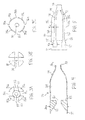
FIG. 1 is a side view of an embodiment of a system comprising an auger and an enclosure; -
FIG. 2 is a side view depicting a portion of a stent used with the system ofFIG. 1 ; -
FIGS. 3A-3C are, respectively, cross-sectional views of the apparatus ofFIG. 1 as taken along lines A--A, B--B and C-C; -
FIG. 4 is a side-sectional view of the enclosure ofFIG. 1 ; -
FIG. 5 is a side view of the enclosure ofFIG. 1 ; and -
FIG. 6 depicts an exemplary stent-graft having a portion that may be deployed using the system ofFIGS. 1-5 . - It is to be understood that the components in the Figures are not necessarily to scale, emphasis instead being placed upon illustrating the principles taught herein. Moreover, in the Figures, like referenced numerals designate corresponding parts throughout the different views.
- In the present application, the term "proximal" refers to a direction that is generally closest to the heart during a medical procedure, while the term "distal" refers to a direction that is furthest from the heart during a medical procedure.
- Referring to
FIGS. 1-2 , a first embodiment of anapparatus 20 is shown for deploying a portion of a stent. Theapparatus 20 generally comprises acannula 30 having anouter surface 31, and anauger 40 having a region that is coupled to theouter surface 31 of thecannula 30. - The
cannula 30 may be incorporated as part of a broader stent or stent-graft delivery system, and may span a longitudinal length in which a distal segment extends outside of a patient's body, and a proximal segment, including theauger 40, is delivered towards a target site inside of a patient's body. Thecannula 30 may be used as an inner cannula, to the extent that one or more outer cannulas or sheaths are disposed coaxially over thecannula 30. For example, a stent-graft may be disposed over an exterior surface of thecannula 30 and within one or more outer cannulas or sheaths, thereby encompassing the stent-graft during a delivery stage. - The
cannula 30 may comprise a tubular member having a lumen sized to allow thecannula 30 to be advanced over a wire guide during delivery. A proximal region of thecannula 30 may be integrally formed with, or externally coupled to, anatraumatic tip 35. Theatraumatic tip 35 may comprise proximal anddistal regions central region 38 disposed therebetween. The proximal anddistal regions central region 38, with a first taper allowing for a smooth transition between theproximal region 36 and thecentral region 38, and a second taper allowing for a smooth transition between thedistal region 37 and thecentral region 38. - The
auger 40 comprises a proximal end 41, adistal end 42, a plurality ofhelical turns 43 disposed therebetween, andvalleys 44 disposed between thehelical turns 43, as shown inFIGS. 1-2 . As will be described further below, a portion of astent 60 may be secured within thevalleys 44 between adjacenthelical turns 43. - In one non-limiting example, the
auger 40 may be secured directly to theouter surface 31 of thecannula 30 using a suitable mechanism, such as a solder, weld, mechanical attachment, friction fit, or combination of these or other techniques and mechanisms. Alternatively, theauger 40 may be secured to an outer surface of a cylindrical supporting member, such as a steel tube, which in turn is securely disposed around theouter surface 31 of thecannula 30 using any of the aforementioned techniques. - The
exemplary auger 40 may be formed from stainless steel, Nitinol, titanium, or other suitable biocompatible materials. In one example, theauger 40 is formed from a material that has radiopaque properties. - The
apparatus 20 also comprises anenclosure 70 for housing theauger 40. Theenclosure 70 comprises afirst end 71 having an outer diameter dc1, and asecond end 72 having a second outer diameter dc2, as best seen inFIGS. 1 and4 . It is noted that the diameter at thefirst end 71 of theenclosure 70 can be larger to accommodate the provision of the helical turns 43 of theauger 40, while still providing spacing between an outermost surface of the helical turns 43 and an inner surface of theenclosure 70 to ensure that the helical turns 43 can rotate relative to theenclosure 70, as explained further below. Asecond end 72 of theenclosure 70 may be positioned distally of theauger 40, as shown inFIG. 1 , and the second outer diameter dc2 may be slightly larger than theouter surface 31 of thecannula 30. Ataper 74 reduces the diameter of theenclosure 70 between the first end having the outer diameter dc1 and the second end having the reduced outer diameter dc2. - In the examples shown, the
first end 71 of theenclosure 70 is the proximal end, while thesecond end 72 of theenclosure 70 is the distal end. However, in other embodiments, the axial orientation of theenclosure 70 may be reversed. For example, theenclosure 70 may have thefirst end 71 of greater diameter located distally, while thesecond end 72 of lesser diameter is located proximally, and a reverse rotational sequence of deployment may be used relative to the manner described herein. - The
enclosure 70 also comprises a plurality of struts separated by a plurality of slots. Each of the struts and slots has proximal and distal ends, and are generally parallel to each other in a direction running along a longitudinal axis of the apparatus, as shown inFIG. 1 . In this non-limiting example, fourstruts 75a-75d are depicted as being separated by fourslots 76a-76d, as shown inFIGS. 1-2 ,3A-3C and 5 . However, it will be appreciated that greater or fewer number than four slots and four struts may be provided for coupling selected proximal apices of astent 60 to theenclosure 70, as explained further below. - Each of the
slots 76a-76d hasproximal regions 77 anddistal regions 78. Theproximal regions 77 have a width w1, which is greater than a width w2 of thedistal regions 78, as depicted inFIG. 5 . The widening of theproximal regions 77 of theslots 76a-76d allows a widenedsecurement region 67 of thestent 60 to be radially advanced only through theproximal regions 77 of their associated slots. - In particular, the widened
securement region 67 comprises a width w3, which is less than the width w1 of theproximal regions 77 of the slots, but greater than the width w2 of thedistal regions 78, as indicated by the dimensions inFIGS. 5-6 , and depicted in an assembled state ofFIG. 2 . The width w2 of thedistal regions 78 of theslots 76a-76d is greater than a width w4 ofproximal extensions 66 of thestent 60, which may be disposed adjacent to the widenedsecurement regions 67, thereby allowing theproximal extensions 66 to extend through an associated slot, as depicted inFIG. 2 . - In an embodiment, the
enclosure 70 is designed to cooperate with at least a portion of theatraumatic tip 35. Thedistal region 37 of theatraumatic tip 35 may comprise an outer surface that corresponds to the shape of an inner surface at a proximal region of theenclosure 70. In particular, theenclosure 70 comprises a proximalinner taper 81, as shown inFIG. 4 . The outer surface of thedistal region 37 of theatraumatic tip 35 generally annularly abuts the proximalinner taper 81 in the assembled state ofFIGS. 1-2 . - In accordance with some embodiments, the
enclosure 70 can rotate circumferentially relative to theatraumatic tip 35 and thecannula 30. Notably, the proximalinner taper 81 of theenclosure 70 is disposed around thedistal region 37 of theatraumatic tip 35, while thedistal end 72 of theenclosure 70 is disposed around theouter surface 31 of thecannula 30. Since the proximal and distal regions of theenclosure 70 are not secured to theatraumatic tip 35 and thecannula 30, respectively, theenclosure 70 can rotate circumferentially relative to these components. - A
distal stop member 79 may be positioned adjacent to thedistal end 72 of theenclosure 70, as shown inFIG. 1 . Thedistal stop member 79 allows theenclosure 70 to rotate relative to thecannula 30, but prevents theenclosure 70 from sliding distally over thecannula 30. Thedistal stop member 79 may be formed integrally with thecannula 30, or as an external component secured to theouter surface 31 of the cannula, and may comprise any suitable biocompatible material. - The proximal
inner taper 81 of theenclosure 70 extends inward to anopening 82, shown inFIG. 4 , which has a diameter that allows passage of thecannula 30 so that thecannula 30 can be coupled to theatraumatic tip 35. Moreover, a steppedsurface 83 is provided at select locations just distal to theopening 82, as shown inFIG. 4 . The steppedsurface 83 may be generally perpendicular to the longitudinal axis of thecannula 30. The steppedsurface 83 may be positioned in the spaces that are in-between theslots 76a-76d, as depicted inFIG. 5 . In other words, the steppedsurface 83 is positioned only beneath the plurality ofstruts 75a-75d, and therefore, does not impede advancement of struts of thestent 60 through theslots 76a-76d. The steppedsurface 83 may reduce the possibility that the struts of thestent 60 become inadvertently lodged under thestruts 75a-75d of theenclosure 70. Preferably, the proximal end 41 of theauger 40 is disposed immediately adjacent to the steppedsurface 83 of theenclosure 70, as depicted inFIG. 1 . - The
enclosure 70 also comprises amain housing 84, which is disposed between the steppedsurface 83 and thedistal end 72, as shown inFIG. 4 . Themain housing 84 is sized for housing theauger 40 therein, and has an inner diameter that remains larger than the auger along its longitudinal length, thereby permitting rotation of theauger 40 within themain housing 84. - The
enclosure 70 may be formed from stainless steel, Nitinol, polymers, or other suitable biocompatible materials. Moreover, theenclosure 70 may be manufactured as a single component, or multiple components that are secured together. In some embodiments, theenclosure 70 may be manufactured by forming an outer shell of material, and then inserting material that forms the proximalinner taper 81 and the steppedsurface 83, and separately cutting theslots 76a-76d into the outer shell. - Referring to
FIG. 6 , an exemplary stent-graft 50, which may be deployed using theapparatus 20 ofFIGS. 1-5 , has a proximally-locatedstent 60 coupled to thegraft material 90. In this non-limiting embodiment, thestent 60 may be manufactured from a continuous cylinder into which a pattern may be cut by a laser or by chemical etching to produce slits in the wall of the cylinder. The resulting structure may then be heat set to give it a desired final configuration. - The
stent 60 has proximal anddistal ends proximal apices 63 disposed near theproximal end 61 of thestent 60, and a series ofdistal apices 69 disposed near thedistal end 62 of thestent 60. A plurality ofstrut segments proximal apices 63 and the series ofdistal apices 69, as shown inFIG. 6 . The series ofproximal apices 63 are each disposed proximally beyond aproximal end 92 of thegraft 90, and the series ofdistal apices 69 of thestent 60 are each disposed distal to theproximal end 92 of thegraft 90. - In
FIG. 6 , each of theproximal apices 63 comprises anend region 64 having anintegral barb 77 formed therein. Thebarb 77 may be formed by laser cutting a desired barb shape into theend regions 64. A slit 76 therefore is formed into eachend region 64 after the desired barb shape is formed, as shown inFIG. 6 . Once the desired barb shape is cut, a main body of thebarb 77 may be bent in a radially outward direction with respect to theend region 64. The angle may comprise any acute angle, or alternatively may be substantially orthogonal or obtuse. If desired, thebarb 77 may be sharpened, for example, by grinding the tip of the barb, to facilitate engagement at a target tissue site. - In
FIG. 6 , at least one pair of adjacent,proximal apices 63 may comprise different features. In particular, alternatingproximal apices 63 terminate at theend regions 64 housing thebarbs 77. However, other alternatingproximal apices end regions 64. The coupling regions of theproximal apices proximal extensions 66 and the widenedsecurement regions 67, as shown inFIG. 6 . For thisexemplary stent 60, a total of eight proximal apices are provided around the circumference of the stent, though only four apices are depicted in the side view ofFIG. 6 for illustrative purposes. Accordingly, in the example having a total of eight proximal apices with alternating features, four of the apices around the circumference of the stent will comprise onlyproximal apices 63 that terminate at theend regions 64 housing thebarbs 77, while the other four proximal apices will have the coupling regions comprising the narrowerproximal extensions 66 and the widenedsecurement regions 67, as depicted by theproximal apices FIG. 6 . In this example, the coupling regions of theproximal apices slots enclosure 70, as depicted inFIG. 2 , while two other proximal apices having coupling regions would be coupled to theslots 76c and 76d in a similar manner. - For the exemplary stent of
FIG. 6 , when the proximal apices having coupling regions are secured within theenclosure 70, it should be noted that the alternatingproximal apices 63 without coupling regions (i.e., those terminating at the end regions 64) may be pulled radially inward in an indirect manner by thestrut segments stent 60 may be partially or fully restrained during delivery. - For illustrative purposes, it should be noted that the alternating
proximal apices 63 without coupling regions (i.e., those terminating at the end regions 64) are not depicted inFIG. 2 ; rather,FIG. 2 depicts the presence of only proximal apices having coupling regions comprising the narrowerproximal extensions 66 and the widenedsecurement regions 67. In other embodiments, however, each of the proximal apices of thestent 60 may in fact be provided with such coupling regions. Moreover, in yet other embodiments, the coupling regions need not be located on the proximal apices, but may be positioned on other regions of the stent. - Referring still to
FIG. 6 , the first and secondangled strut segments distal transition region 85. In the embodiment ofFIG. 6 , each of thedistal apices 69 comprises anend region 88 having a suture bore 89 formed therein. Further, each of thedistal apices 69 comprises an imaging bore 87 adapted to receive animaging element 87a, such as a radiopaque marker. The imaging bore 87 is disposed proximal to the suture bore 89, and the imaging bore 87 is adapted to be aligned with theproximal end 92 of thegraft 90, thereby allowing theimaging element 87a associated with the imaging bore 87 to significantly enhance imaging directly at theproximal end 92 of thegraft 90. Further, thestent 60 may comprises at least onebarb 86 that is integrally formed along thedistal transition region 85 at a location proximal to the imaging bore 87, as shown inFIG. 6 . - In this manner, the
stent 60 may be used as an attachment stent for endovascular graft fixation. For example, thegraft material 90 may overlap with an aneurysm to seal off fluid flow into the aneurysm, while theproximal end 61 of thestent 60 may extend in a proximal direction away from the graft material, e.g., to engage a healthy portion of a vessel wall away from a diseased portion of the aneurysm. As will be apparent, one or more additional stents may be coupled to an inner or outer surface of thegraft material 90, i.e., at a location distal to thestent 60, to help maintain patency throughout the graft material. - Expansion of the
stent 60 is at least partly provided by theangled strut segments FIG. 6 . Thestent 60 may be formed from any suitable material, such as a laser-cut Nitinol cannula. If manufactured from Nitinol, thestent 60 may be inclined to assume the expanded state shown inFIG. 6 upon removal of a delivery sheath or engagement with theenclosure 70, as explained above. - The
stent 60 has a reduced diameter delivery state so that it may be advanced to a target location within a vessel or duct. Thestent 60 also has an expanded deployed state to apply a radially outward force upon at least a portion of a vessel or duct, e.g., to maintain patency within a passageway, or to hold open the lumen of a graft. In the expanded state, fluid flow is allowed through a central lumen of thestent 60. Further, the struts of thestent 60 may comprise a substantially flat wire profile or may comprise a rounded profile. As best seen inFIG. 2 , the struts of thestent 60 generally comprise a flat wire profile. - The
stent 60 may be manufactured from a super-elastic material. Solely by way of example, the super-elastic material may comprise a shape-memory alloy, such as a nickel titanium alloy (Nitinol). If thestent 60 comprises a self-expanding material such as Nitinol, the stent may be heat-set into the desired expanded state, whereby thestent 60 can assume a relaxed configuration in which it assumes the preconfigured first expanded inner diameter upon application of a certain cold or hot medium. In other embodiments, thestent 60 may be made from other metals and alloys that allow thestent 60 to return to its original, expanded configuration upon deployment, without inducing a permanent strain on the material due to compression. Solely by way of example, thestent 60 may comprise other materials such as stainless steel, cobalt-chrome alloys, amorphous metals, tantalum, platinum, gold and titanium. Thestent 60 also may be made from non-metallic materials, such as thermoplastics and other polymers. - In an exemplary method of use, the
proximal apices 63 of thestent 60 having coupling regions are secured through theslots 76a-76d in a delivery state, as shown inFIG. 2 . For example, the firstproximal apex 63a may be positioned over theslot 76a, and the widenedsecurement region 67 of the firstproximal apex 63a may be aligned with, and pressed radially within, the widenedproximal region 77 of theslot 76a. Theproximal apex 63a may be pushed radially inward and held steady, while thecannula 30 and theauger 40 are rotated in a first direction, thereby allowing the widenedsecurement region 67 of the proximal apex 63a to be advanced in a proximal to distal direction by theauger 40. At this time, the widenedsecurement region 67 is positioned withinvalleys 44 between adjacent helical turns 43, and the narrowerproximal extension 66 extends radially through theslot 76a, as shown inFIG. 2 . Notably, since the widenedsecurement region 67 comprises the width w3, which is greater than the width w2 of thedistal region 78 of theslot 76a, as explained above, the widenedsecurement region 67 is captured radially within theslot 76a, despite any tendency for this portion of thestent 60 to want to self-expand radially outward. Optionally, the widenedsecurement region 67 may comprise a concave end surface 68, as shown inFIG. 6 , which may follow the contour of thevalleys 44 between the helical turns 43 of theauger 40 in the delivery state. - Similarly, a second
proximal apex 63b may be positioned over theslot 76b, as depicted inFIG. 2 , and the widenedsecurement region 67 may be aligned with, and pressed radially within, the widenedproximal region 77 of theslot 76b, while thecannula 30 and theauger 40 are rotated in the first direction to advance the widenedsecurement region 67 of the secondproximal apex 63b in a proximal to distal direction by theauger 40. This process may be repeated until all of the proximal apices of thestent 60 having such coupling regions are secured within theenclosure 70 through the slots, in the manner shown inFIG. 2 . - The coupling shown in
FIG. 2 secures portions of thestent 60 within theenclosure 70 in a manner that may subsequently facilitate insertion of the subassembly comprising thecannula 30 and the stent-graft 50 into an outer sheath. As will be apparent, the outer sheath is configured to radially restrain other regions of the stent-graft 50 for delivery to a target site within a patient's anatomy, as described in the exemplary sequence below. - An introducer, similar to that described in
PCT application WO-98/5761 graft 50.PCT application WO-98/5761 graft 50. Rather, thecannulas 30 and theauger 40 of the present embodiments may be incorporated as part of the deployment system with the stent-graft 50 being positioned coaxially between thecannula 30 and the outer sheath. A mechanism, such as a pin vise, may be employed to prevent inadvertent rotation of thecannula 30 prior to the intended rotation as described in the present application. - A wire guide may be advanced to the target site, and the
cannula 30 may be advanced over the wire guide to position theapparatus 20 at the desired location in proximity to the target site, with theatraumatic tip 35 reducing the likelihood of injury to bodily passageways during delivery. The outer sheath is disposed over thecannula 30 and the stent-graft 50 during insertion to the target site. Upon proper positioning at the target site using a desired imaging modality, the outer sheath is then retracted to expose at least a portion of thestent 60. At this time, portions of thestent 60 near theproximal end 61 that are not held within theenclosure 70 may partially deploy radially outward, thereby providing an amount of slack that may facilitate subsequent longitudinal movement of the portions held within theenclosure 70. - When the
stent 60 is at least partially exposed, and it is desirable to deploy theproximal end 61 of thestent 60, thecannula 30 may be rotated in a second direction, i.e., in a reverse manner from which the widenedsecurement regions 67 were coupled within theenclosure 70. In this manner, theauger 40 is rotated in the second direction, along with thecannula 30, to thereby advance the widenedsecurement regions 67 in a distal to proximal direction within theirrespective slots 76a-76d. - The
proximal apices 63 of thestent 60 can self-deploy in a radially outward direction once the widenedsecurement regions 67 are advanced proximally so that they are aligned with the widenedproximal regions 67 of theirrespective slots 76a-76d. Notably, the angled shape of thedistal region 37 of theatraumatic tip 35 may provide a ramp-like element to facilitate radial outward deployment of the widenedsecurement regions 67. Further, the steppedsurface 83, which may be positioned in the spaces in-between theslots 76a-76d, may reduce the likelihood that the proximal apices of thestent 60 become inadvertently lodged under thestruts 75a-75d. - During the process of advancing the widened
securement regions 67 in a distal to proximal direction within theirrespective slots 76a-76d, thecannula 30 and theenclosure 70 may be advanced distally. In this manner, theproximal apices 63 of thestent 60 will not be pulled proximally, relative to the remainder of the stent-graft 50, in a manner that imposes significant strain upon theproximal apices 63 during deployment. Further, as noted above, an amount of slack may be provided to portions of thestent 60 after partial pullback of an outer sheath, and such slack may further reduce strain imposed upon the proximal apices during advancement by theauger 40. - After the restrained
proximal apices 63 of thestent 60 self-deploy in a radially outward direction through theproximal regions 77 of theslots 76a-76d, the remainder of the stent-graft 50 may be deployed by further retraction of the outer sheath or actuation of any other devices that are radially constraining the remainder of the stent-graft 50. - Advantageously, the
proximal end 61 of thestent 60 is radially restrained without the use of convention trigger wires that span a full longitudinal length of the delivery system. Accordingly, the radial profile of the delivery system may be reduced without the provision of multiple trigger wires and one or more associated sleeves to house the trigger wires, thereby reducing packing density of the system. Moreover, deployment may be simplified as reduced deployment forces are expected to be needed relative to the use of conventional trigger wires. - As a further advantage, deployment of the
stent 60 using theapparatus 20 comprising theauger 40 may allow for more precise positioning of thestent 60. In particular, deployment using theauger 40 may provide a more controlled radial release of the associated portion of thestent 60, whereas the release of conventional trigger wires may require higher deployment forces that can cause a portion of the stent to jump longitudinally, thereby potentially deploying the stent offset from the intended target site. - As yet a further advantage, during deployment of the
stent 60, theenclosure 70 can rotate circumferentially relative to theatraumatic tip 35 and thecannula 30. This allows the orientation of theenclosure 70 and theproximal apices 63 to remain generally the same while thecannula 30 and theauger 40 are rotated circumferentially during deployment. Still further, theenclosure 70 encloses theauger 40 and reduces the possibility that theauger 40 can interfere with, damage, or snag various endovascular, stent or graft structures during manipulation and removal of the delivery device. - In another embodiment, the axial orientation of the enclosure may be reversed, i.e., such that the widened portion of the
slots 76a-76d resides at the distal end of theenclosure 70. In this embodiment, the portion of the stent to be coupled within theenclosure 70 is loaded in a similar manner described above but with rotation of thecannula 30 andauger 40 in an opposite circumferential direction relative to the example ofFIGS. 1-2 , and further, release of the coupled portion of the stent occurs in the opposite circumferential direction that achieves this function inFIGS. 1-2 . - Moreover, while one
exemplary stent 60 is shown and described inFIGS. 2 and6 , various other stent configurations may be used in conjunction with theauger 40 and theenclosure 70 ofFIGS. 1-5 . Further, such stents may be deployed alone, or as part of a stent-graft system, as depicted herein. - While various embodiments of the invention have been described, the invention is not to be restricted except in light of the attached claims and their equivalents. Moreover, the advantages described herein are not necessarily the only advantages of the teachings herein and it is not necessarily expected that every embodiment of the invention will achieve all of the advantages described.
- All optional and preferred features and modifications of the described embodiments and dependent claims are usable in all aspects of the invention taught herein. Furthermore, the individual features of the dependent claims, as well as all optional and preferred features and modifications of the described embodiments are combinable and interchangeable with one another.
- The disclosures in United States
patent application number 61/745,171
Claims (15)
- A system for deploying at least a portion of a stent, the system including:a cannula provided with an outer surface;an auger including proximal and distal ends and a plurality of turns disposed therebetween, wherein the auger is coupled to the outer surface of the cannula;a stent to be deployed including a portion dimensioned to be disposed within a valley of the auger, wherein rotation of the cannula and the auger advances the portion of the stent in a predetermined longitudinal direction.
- A system according to claim 1, including an enclosure encircling the auger.
- A system according to claim 2, wherein the enclosure includes a plurality of struts separated by a plurality of slots, where the portion of the stent extends through one of the plurality of slots in a delivery state.
- A system according to claim 3, wherein each of the plurality of struts and each of the plurality of slots are generally parallel to each other in a direction running along a longitudinal axis of the apparatus.
- A system according to claim 3 or 4, wherein at least one of the plurality of slots includes proximal and distal regions and a width at the proximal region greater than a width at the distal region.
- A system according to claim 5, wherein the stent to be deployed includes a widened securement region, wherein the widened securement region includes a width less than a width of the proximal region of the slot and greater than a width at the distal region of the slot.
- A system according to claim 6, wherein the stent to be deployed includes a proximal extension disposed adjacent to the widened securement region, wherein a width of the proximal extension is less than the width of the distal region of the slot.
- A system according to any one of claims 2 to 7, wherein the enclosure is circumferentially rotatable relative to the cannula.
- A system according to any one of claims 2 to 8, including an atraumatic tip coupled to the cannula, wherein at least a portion of the atraumatic tip is disposed beneath the enclosure, and wherein the enclosure can rotate circumferentially relative to the atraumatic tip and the cannula.
- A system according to any one of claims 2 to 9, including a distal stop member coupled to the cannula and positioned adjacent to a distal end of the enclosure, wherein the distal stop member allows the enclosure to rotate relative to the cannula, but prevents the enclosure from sliding distally over the cannula.
- A system for deploying at least a portion of a stent, the system including:a cannula having an outer surface;an auger including proximal and distal ends and a plurality of turns disposed therebetween, wherein the auger is coupled to the outer surface of the cannula;a stent to be deployed including a portion dimensioned to be disposed within a valley of the auger, wherein rotation of the cannula and the auger advances the portion of the stent in a predetermined longitudinal direction; andan enclosure encircling the auger, wherein the enclosure includes a plurality of struts separated by a plurality of slots, and wherein the portion of the stent extends through one of the plurality of slots in a delivery state.
- A system according to claim 11, wherein at least one of the plurality of slots includes proximal and distal regions and a width at the proximal region is greater than a width at the distal region.
- A system according to claim 12, wherein the stent to be deployed includes a widened securement region, wherein the widened securement region includes a width that is less than a width of the proximal region of the slot and greater than a width at the distal region of the slot.
- A system according to claim 13, wherein the stent to be deployed includes a proximal extension disposed adjacent to the widened securement region, wherein a width of the proximal extension is less than the width of the distal region of the slot.
- A system according to any one of claims 11 to 14, wherein the enclosure is circumferentially rotatable relative to the cannula.
Applications Claiming Priority (1)
| Application Number | Priority Date | Filing Date | Title |
|---|---|---|---|
| US201261745171P | 2012-12-21 | 2012-12-21 |
Publications (2)
| Publication Number | Publication Date |
|---|---|
| EP2745809A1 true EP2745809A1 (en) | 2014-06-25 |
| EP2745809B1 EP2745809B1 (en) | 2018-06-13 |
Family
ID=49841514
Family Applications (1)
| Application Number | Title | Priority Date | Filing Date |
|---|---|---|---|
| EP13197539.3A Active EP2745809B1 (en) | 2012-12-21 | 2013-12-16 | Systems for deploying a portion of a stent using an auger-style device |
Country Status (2)
| Country | Link |
|---|---|
| US (2) | US9655756B2 (en) |
| EP (1) | EP2745809B1 (en) |
Families Citing this family (7)
| Publication number | Priority date | Publication date | Assignee | Title |
|---|---|---|---|---|
| US10159586B2 (en) | 2015-06-29 | 2018-12-25 | 480 Biomedical Inc. | Scaffold loading and delivery systems |
| US11622872B2 (en) | 2016-05-16 | 2023-04-11 | Elixir Medical Corporation | Uncaging stent |
| ES2873887T3 (en) | 2016-05-16 | 2021-11-04 | Elixir Medical Corp | Stent release |
| US12599490B2 (en) | 2017-05-25 | 2026-04-14 | Elixir Medical Corporation | Uncaging stent |
| CN115867235A (en) * | 2020-03-24 | 2023-03-28 | 铸造有限责任公司 | Inflatable instruments and related systems and methods |
| EP4125738A1 (en) | 2020-03-24 | 2023-02-08 | The Foundry, LLC | Expandable devices and associated systems and methods |
| EP4125739A1 (en) | 2020-03-24 | 2023-02-08 | The Foundry, LLC | Expandable devices |
Citations (6)
| Publication number | Priority date | Publication date | Assignee | Title |
|---|---|---|---|---|
| US5626604A (en) * | 1995-12-05 | 1997-05-06 | Cordis Corporation | Hand held stent crimping device |
| WO1998005761A1 (en) | 1996-08-07 | 1998-02-12 | The General Hospital Corporation | Age-1 polypeptides and related molecules and methods |
| US5776142A (en) * | 1996-12-19 | 1998-07-07 | Medtronic, Inc. | Controllable stent delivery system and method |
| JP2002291756A (en) * | 2001-04-03 | 2002-10-08 | Next:Kk | Atherosclerosis removal / stent placement device, stent collection device, and operation device of these devices |
| US20090270966A1 (en) * | 2008-04-24 | 2009-10-29 | Medtronic Vascular, Inc. | Stent Graft System and Method of Use |
| WO2010056522A2 (en) * | 2008-11-14 | 2010-05-20 | Medtronic Vascular Inc. | Coil stent delivery system and method of use |
Family Cites Families (34)
| Publication number | Priority date | Publication date | Assignee | Title |
|---|---|---|---|---|
| US4732154A (en) * | 1984-05-14 | 1988-03-22 | Surgical Systems & Instruments, Inc. | Rotary catheter system |
| US5078723A (en) * | 1989-05-08 | 1992-01-07 | Medtronic, Inc. | Atherectomy device |
| US5201757A (en) | 1992-04-03 | 1993-04-13 | Schneider (Usa) Inc. | Medial region deployment of radially self-expanding stents |
| US5480423A (en) | 1993-05-20 | 1996-01-02 | Boston Scientific Corporation | Prosthesis delivery |
| US5824041A (en) | 1994-06-08 | 1998-10-20 | Medtronic, Inc. | Apparatus and methods for placement and repositioning of intraluminal prostheses |
| US5653722A (en) * | 1995-01-03 | 1997-08-05 | Kieturakis; Maciej J. | Anterograde/retrograde spiral dissector and method of use in vein grafting |
| US6379334B1 (en) * | 1997-02-10 | 2002-04-30 | Essex Technology, Inc. | Rotate advance catheterization system |
| US6077296A (en) | 1998-03-04 | 2000-06-20 | Endologix, Inc. | Endoluminal vascular prosthesis |
| BR9900959A (en) | 1999-04-26 | 2000-11-07 | Luciano Jose Teixeira Moreira | Pipe repair introducer and positioner |
| US6858034B1 (en) | 1999-05-20 | 2005-02-22 | Scimed Life Systems, Inc. | Stent delivery system for prevention of kinking, and method of loading and using same |
| US7147657B2 (en) | 2003-10-23 | 2006-12-12 | Aptus Endosystems, Inc. | Prosthesis delivery systems and methods |
| US7942924B1 (en) | 2002-03-04 | 2011-05-17 | Endovascular Technologies, Inc. | Staged endovascular graft delivery system |
| US7264632B2 (en) | 2002-06-07 | 2007-09-04 | Medtronic Vascular, Inc. | Controlled deployment delivery system |
| US7611528B2 (en) | 2003-01-24 | 2009-11-03 | Medtronic Vascular, Inc. | Stent-graft delivery system |
| US7101390B2 (en) | 2003-05-27 | 2006-09-05 | Scimed Life Systems, Inc. | Staged deployment endograft |
| US20080264102A1 (en) | 2004-02-23 | 2008-10-30 | Bolton Medical, Inc. | Sheath Capture Device for Stent Graft Delivery System and Method for Operating Same |
| US8292943B2 (en) | 2003-09-03 | 2012-10-23 | Bolton Medical, Inc. | Stent graft with longitudinal support member |
| US9198786B2 (en) | 2003-09-03 | 2015-12-01 | Bolton Medical, Inc. | Lumen repair device with capture structure |
| JP4850712B2 (en) | 2003-10-10 | 2012-01-11 | ウィリアム・クック・ヨーロッパ・アンパルトセルスカブ | Stent graft retention system |
| AU2005262541B2 (en) | 2004-06-16 | 2011-04-21 | Cook Incorporated | Thoracic deployment device and stent graft |
| US7780650B2 (en) * | 2005-05-04 | 2010-08-24 | Spirus Medical, Inc. | Rotate-to-advance catheterization system |
| EP1991179B1 (en) | 2006-02-27 | 2013-03-20 | William A. Cook Australia Pty. Ltd. | Retention of stents |
| DE102006053748B3 (en) | 2006-11-09 | 2008-04-10 | Jotec Gmbh | Insert system for inserting and releasing e.g. endovascular stent, has fixing system with cover unit including pivoting units axially extending in proximal direction of insert system, and retaining unit arranged proximal to cover unit |
| JP5662683B2 (en) | 2007-02-09 | 2015-02-04 | タヘリ ラドュカ エルエルシー | Apparatus and method for deploying an implantable device in a body |
| FR2913879B1 (en) | 2007-03-21 | 2009-06-12 | Perouse Soc Par Actions Simpli | DEVICE FOR LAGGING A RADIALLY EXPANSIBLE IMPLANT, NECESSARY FOR TREATMENT AND METHOD OF RELAUNCHING |
| US8092510B2 (en) | 2007-07-25 | 2012-01-10 | Cook Medical Technologies Llc | Retention wire for self-expanding stent |
| US8157853B2 (en) | 2008-01-24 | 2012-04-17 | Medtronic, Inc. | Delivery systems and methods of implantation for prosthetic heart valves |
| DK2254514T3 (en) | 2008-01-24 | 2018-12-17 | Medtronic Inc | STENTS FOR HEART VALVE PROSTHESIS |
| DE102008008412A1 (en) | 2008-02-09 | 2009-08-13 | Zf Friedrichshafen Ag | Torque transmission device of a motor vehicle |
| US20090306760A1 (en) | 2008-06-06 | 2009-12-10 | Bay Street Medical | Prosthesis and delivery system |
| JP5284165B2 (en) | 2009-03-31 | 2013-09-11 | テルモ株式会社 | Biological organ lesion improvement device |
| US8771333B2 (en) | 2009-06-23 | 2014-07-08 | Cordis Corporation | Stent-graft securement device |
| US20110251664A1 (en) | 2010-04-08 | 2011-10-13 | Medtronic Vascular, Inc. | Short Legged Bifurcated Stent Graft Distal Capture Element and Method |
| US8920485B2 (en) * | 2012-04-13 | 2014-12-30 | Medtronic Vascular, Inc. | Stent-graft delivery system having a rotatable single shaft tip capture mechanism |
-
2013
- 2013-12-13 US US14/105,921 patent/US9655756B2/en active Active
- 2013-12-16 EP EP13197539.3A patent/EP2745809B1/en active Active
-
2017
- 2017-04-14 US US15/487,849 patent/US10639180B2/en active Active
Patent Citations (6)
| Publication number | Priority date | Publication date | Assignee | Title |
|---|---|---|---|---|
| US5626604A (en) * | 1995-12-05 | 1997-05-06 | Cordis Corporation | Hand held stent crimping device |
| WO1998005761A1 (en) | 1996-08-07 | 1998-02-12 | The General Hospital Corporation | Age-1 polypeptides and related molecules and methods |
| US5776142A (en) * | 1996-12-19 | 1998-07-07 | Medtronic, Inc. | Controllable stent delivery system and method |
| JP2002291756A (en) * | 2001-04-03 | 2002-10-08 | Next:Kk | Atherosclerosis removal / stent placement device, stent collection device, and operation device of these devices |
| US20090270966A1 (en) * | 2008-04-24 | 2009-10-29 | Medtronic Vascular, Inc. | Stent Graft System and Method of Use |
| WO2010056522A2 (en) * | 2008-11-14 | 2010-05-20 | Medtronic Vascular Inc. | Coil stent delivery system and method of use |
Also Published As
| Publication number | Publication date |
|---|---|
| US9655756B2 (en) | 2017-05-23 |
| US20140180384A1 (en) | 2014-06-26 |
| US20170216067A1 (en) | 2017-08-03 |
| US10639180B2 (en) | 2020-05-05 |
| EP2745809B1 (en) | 2018-06-13 |
Similar Documents
| Publication | Publication Date | Title |
|---|---|---|
| US10695205B2 (en) | Systems and methods for securing and releasing a portion of a stent | |
| US10993823B2 (en) | Systems and methods for deploying a portion of a stent using at least one coiled member | |
| US9629733B2 (en) | Stents having barbs protected during delivery | |
| US10905575B2 (en) | Circumferential trigger wire for deploying an endoluminal prosthesis | |
| US10639180B2 (en) | Systems and methods for deploying a portion of a stent using an auger-style device | |
| US9144510B2 (en) | Systems and methods for deploying a portion of a stent using at least one coiled member | |
| US9192497B2 (en) | Apparatus and methods for improved stent deployment | |
| EP3078353B1 (en) | Endoluminal prosthesis introducer | |
| EP2777654A2 (en) | Wireless medical device release mechanism | |
| US20160367389A1 (en) | Implant introducer with helical trigger wire | |
| EP2727563B1 (en) | Apparatus for improved stent deployment | |
| EP2674135B1 (en) | Systems and methods for deploying a portion of a stent using at least one coiled member | |
| EP2842526B1 (en) | System for deploying at least a portion of a stent | |
| EP2777652B1 (en) | Loading tool for capturing stent points |
Legal Events
| Date | Code | Title | Description |
|---|---|---|---|
| PUAI | Public reference made under article 153(3) epc to a published international application that has entered the european phase |
Free format text: ORIGINAL CODE: 0009012 |
|
| 17P | Request for examination filed |
Effective date: 20131216 |
|
| AK | Designated contracting states |
Kind code of ref document: A1 Designated state(s): AL AT BE BG CH CY CZ DE DK EE ES FI FR GB GR HR HU IE IS IT LI LT LU LV MC MK MT NL NO PL PT RO RS SE SI SK SM TR |
|
| AX | Request for extension of the european patent |
Extension state: BA ME |
|
| R17P | Request for examination filed (corrected) |
Effective date: 20141216 |
|
| RBV | Designated contracting states (corrected) |
Designated state(s): AL AT BE BG CH CY CZ DE DK EE ES FI FR GB GR HR HU IE IS IT LI LT LU LV MC MK MT NL NO PL PT RO RS SE SI SK SM TR |
|
| GRAP | Despatch of communication of intention to grant a patent |
Free format text: ORIGINAL CODE: EPIDOSNIGR1 |
|
| STAA | Information on the status of an ep patent application or granted ep patent |
Free format text: STATUS: GRANT OF PATENT IS INTENDED |
|
| INTG | Intention to grant announced |
Effective date: 20180102 |
|
| RIN1 | Information on inventor provided before grant (corrected) |
Inventor name: VAD, SIDDARTH Inventor name: LEBLANC, JOHNNY Inventor name: HAVEL, WILLIAM J |
|
| GRAS | Grant fee paid |
Free format text: ORIGINAL CODE: EPIDOSNIGR3 |
|
| GRAA | (expected) grant |
Free format text: ORIGINAL CODE: 0009210 |
|
| STAA | Information on the status of an ep patent application or granted ep patent |
Free format text: STATUS: THE PATENT HAS BEEN GRANTED |
|
| AK | Designated contracting states |
Kind code of ref document: B1 Designated state(s): AL AT BE BG CH CY CZ DE DK EE ES FI FR GB GR HR HU IE IS IT LI LT LU LV MC MK MT NL NO PL PT RO RS SE SI SK SM TR |
|
| REG | Reference to a national code |
Ref country code: GB Ref legal event code: FG4D |
|
| REG | Reference to a national code |
Ref country code: CH Ref legal event code: EP Ref country code: AT Ref legal event code: REF Ref document number: 1007701 Country of ref document: AT Kind code of ref document: T Effective date: 20180615 |
|
| REG | Reference to a national code |
Ref country code: IE Ref legal event code: FG4D |
|
| REG | Reference to a national code |
Ref country code: DE Ref legal event code: R096 Ref document number: 602013038812 Country of ref document: DE |
|
| REG | Reference to a national code |
Ref country code: NL Ref legal event code: MP Effective date: 20180613 |
|
| REG | Reference to a national code |
Ref country code: LT Ref legal event code: MG4D |
|
| PG25 | Lapsed in a contracting state [announced via postgrant information from national office to epo] |
Ref country code: BG Free format text: LAPSE BECAUSE OF FAILURE TO SUBMIT A TRANSLATION OF THE DESCRIPTION OR TO PAY THE FEE WITHIN THE PRESCRIBED TIME-LIMIT Effective date: 20180913 Ref country code: NO Free format text: LAPSE BECAUSE OF FAILURE TO SUBMIT A TRANSLATION OF THE DESCRIPTION OR TO PAY THE FEE WITHIN THE PRESCRIBED TIME-LIMIT Effective date: 20180913 Ref country code: FI Free format text: LAPSE BECAUSE OF FAILURE TO SUBMIT A TRANSLATION OF THE DESCRIPTION OR TO PAY THE FEE WITHIN THE PRESCRIBED TIME-LIMIT Effective date: 20180613 Ref country code: CY Free format text: LAPSE BECAUSE OF FAILURE TO SUBMIT A TRANSLATION OF THE DESCRIPTION OR TO PAY THE FEE WITHIN THE PRESCRIBED TIME-LIMIT Effective date: 20180613 Ref country code: SE Free format text: LAPSE BECAUSE OF FAILURE TO SUBMIT A TRANSLATION OF THE DESCRIPTION OR TO PAY THE FEE WITHIN THE PRESCRIBED TIME-LIMIT Effective date: 20180613 Ref country code: ES Free format text: LAPSE BECAUSE OF FAILURE TO SUBMIT A TRANSLATION OF THE DESCRIPTION OR TO PAY THE FEE WITHIN THE PRESCRIBED TIME-LIMIT Effective date: 20180613 Ref country code: LT Free format text: LAPSE BECAUSE OF FAILURE TO SUBMIT A TRANSLATION OF THE DESCRIPTION OR TO PAY THE FEE WITHIN THE PRESCRIBED TIME-LIMIT Effective date: 20180613 |
|
| PG25 | Lapsed in a contracting state [announced via postgrant information from national office to epo] |
Ref country code: LV Free format text: LAPSE BECAUSE OF FAILURE TO SUBMIT A TRANSLATION OF THE DESCRIPTION OR TO PAY THE FEE WITHIN THE PRESCRIBED TIME-LIMIT Effective date: 20180613 Ref country code: RS Free format text: LAPSE BECAUSE OF FAILURE TO SUBMIT A TRANSLATION OF THE DESCRIPTION OR TO PAY THE FEE WITHIN THE PRESCRIBED TIME-LIMIT Effective date: 20180613 Ref country code: GR Free format text: LAPSE BECAUSE OF FAILURE TO SUBMIT A TRANSLATION OF THE DESCRIPTION OR TO PAY THE FEE WITHIN THE PRESCRIBED TIME-LIMIT Effective date: 20180914 Ref country code: HR Free format text: LAPSE BECAUSE OF FAILURE TO SUBMIT A TRANSLATION OF THE DESCRIPTION OR TO PAY THE FEE WITHIN THE PRESCRIBED TIME-LIMIT Effective date: 20180613 |
|
| REG | Reference to a national code |
Ref country code: AT Ref legal event code: MK05 Ref document number: 1007701 Country of ref document: AT Kind code of ref document: T Effective date: 20180613 |
|
| PG25 | Lapsed in a contracting state [announced via postgrant information from national office to epo] |
Ref country code: NL Free format text: LAPSE BECAUSE OF FAILURE TO SUBMIT A TRANSLATION OF THE DESCRIPTION OR TO PAY THE FEE WITHIN THE PRESCRIBED TIME-LIMIT Effective date: 20180613 |
|
| PG25 | Lapsed in a contracting state [announced via postgrant information from national office to epo] |
Ref country code: EE Free format text: LAPSE BECAUSE OF FAILURE TO SUBMIT A TRANSLATION OF THE DESCRIPTION OR TO PAY THE FEE WITHIN THE PRESCRIBED TIME-LIMIT Effective date: 20180613 Ref country code: PL Free format text: LAPSE BECAUSE OF FAILURE TO SUBMIT A TRANSLATION OF THE DESCRIPTION OR TO PAY THE FEE WITHIN THE PRESCRIBED TIME-LIMIT Effective date: 20180613 Ref country code: IS Free format text: LAPSE BECAUSE OF FAILURE TO SUBMIT A TRANSLATION OF THE DESCRIPTION OR TO PAY THE FEE WITHIN THE PRESCRIBED TIME-LIMIT Effective date: 20181013 Ref country code: AT Free format text: LAPSE BECAUSE OF FAILURE TO SUBMIT A TRANSLATION OF THE DESCRIPTION OR TO PAY THE FEE WITHIN THE PRESCRIBED TIME-LIMIT Effective date: 20180613 Ref country code: RO Free format text: LAPSE BECAUSE OF FAILURE TO SUBMIT A TRANSLATION OF THE DESCRIPTION OR TO PAY THE FEE WITHIN THE PRESCRIBED TIME-LIMIT Effective date: 20180613 Ref country code: CZ Free format text: LAPSE BECAUSE OF FAILURE TO SUBMIT A TRANSLATION OF THE DESCRIPTION OR TO PAY THE FEE WITHIN THE PRESCRIBED TIME-LIMIT Effective date: 20180613 Ref country code: SK Free format text: LAPSE BECAUSE OF FAILURE TO SUBMIT A TRANSLATION OF THE DESCRIPTION OR TO PAY THE FEE WITHIN THE PRESCRIBED TIME-LIMIT Effective date: 20180613 |
|
| PG25 | Lapsed in a contracting state [announced via postgrant information from national office to epo] |
Ref country code: SM Free format text: LAPSE BECAUSE OF FAILURE TO SUBMIT A TRANSLATION OF THE DESCRIPTION OR TO PAY THE FEE WITHIN THE PRESCRIBED TIME-LIMIT Effective date: 20180613 Ref country code: IT Free format text: LAPSE BECAUSE OF FAILURE TO SUBMIT A TRANSLATION OF THE DESCRIPTION OR TO PAY THE FEE WITHIN THE PRESCRIBED TIME-LIMIT Effective date: 20180613 |
|
| REG | Reference to a national code |
Ref country code: DE Ref legal event code: R097 Ref document number: 602013038812 Country of ref document: DE |
|
| PLBE | No opposition filed within time limit |
Free format text: ORIGINAL CODE: 0009261 |
|
| STAA | Information on the status of an ep patent application or granted ep patent |
Free format text: STATUS: NO OPPOSITION FILED WITHIN TIME LIMIT |
|
| 26N | No opposition filed |
Effective date: 20190314 |
|
| PG25 | Lapsed in a contracting state [announced via postgrant information from national office to epo] |
Ref country code: SI Free format text: LAPSE BECAUSE OF FAILURE TO SUBMIT A TRANSLATION OF THE DESCRIPTION OR TO PAY THE FEE WITHIN THE PRESCRIBED TIME-LIMIT Effective date: 20180613 Ref country code: DK Free format text: LAPSE BECAUSE OF FAILURE TO SUBMIT A TRANSLATION OF THE DESCRIPTION OR TO PAY THE FEE WITHIN THE PRESCRIBED TIME-LIMIT Effective date: 20180613 |
|
| REG | Reference to a national code |
Ref country code: CH Ref legal event code: PL |
|
| PG25 | Lapsed in a contracting state [announced via postgrant information from national office to epo] |
Ref country code: MC Free format text: LAPSE BECAUSE OF FAILURE TO SUBMIT A TRANSLATION OF THE DESCRIPTION OR TO PAY THE FEE WITHIN THE PRESCRIBED TIME-LIMIT Effective date: 20180613 Ref country code: LU Free format text: LAPSE BECAUSE OF NON-PAYMENT OF DUE FEES Effective date: 20181216 |
|
| REG | Reference to a national code |
Ref country code: BE Ref legal event code: MM Effective date: 20181231 |
|
| PG25 | Lapsed in a contracting state [announced via postgrant information from national office to epo] |
Ref country code: FR Free format text: LAPSE BECAUSE OF NON-PAYMENT OF DUE FEES Effective date: 20181231 |
|
| PG25 | Lapsed in a contracting state [announced via postgrant information from national office to epo] |
Ref country code: AL Free format text: LAPSE BECAUSE OF FAILURE TO SUBMIT A TRANSLATION OF THE DESCRIPTION OR TO PAY THE FEE WITHIN THE PRESCRIBED TIME-LIMIT Effective date: 20180613 Ref country code: BE Free format text: LAPSE BECAUSE OF NON-PAYMENT OF DUE FEES Effective date: 20181231 |
|
| PG25 | Lapsed in a contracting state [announced via postgrant information from national office to epo] |
Ref country code: LI Free format text: LAPSE BECAUSE OF NON-PAYMENT OF DUE FEES Effective date: 20181231 Ref country code: CH Free format text: LAPSE BECAUSE OF NON-PAYMENT OF DUE FEES Effective date: 20181231 |
|
| PG25 | Lapsed in a contracting state [announced via postgrant information from national office to epo] |
Ref country code: MT Free format text: LAPSE BECAUSE OF NON-PAYMENT OF DUE FEES Effective date: 20181216 |
|
| PG25 | Lapsed in a contracting state [announced via postgrant information from national office to epo] |
Ref country code: TR Free format text: LAPSE BECAUSE OF FAILURE TO SUBMIT A TRANSLATION OF THE DESCRIPTION OR TO PAY THE FEE WITHIN THE PRESCRIBED TIME-LIMIT Effective date: 20180613 |
|
| PG25 | Lapsed in a contracting state [announced via postgrant information from national office to epo] |
Ref country code: PT Free format text: LAPSE BECAUSE OF FAILURE TO SUBMIT A TRANSLATION OF THE DESCRIPTION OR TO PAY THE FEE WITHIN THE PRESCRIBED TIME-LIMIT Effective date: 20180613 |
|
| PG25 | Lapsed in a contracting state [announced via postgrant information from national office to epo] |
Ref country code: HU Free format text: LAPSE BECAUSE OF FAILURE TO SUBMIT A TRANSLATION OF THE DESCRIPTION OR TO PAY THE FEE WITHIN THE PRESCRIBED TIME-LIMIT; INVALID AB INITIO Effective date: 20131216 Ref country code: MK Free format text: LAPSE BECAUSE OF NON-PAYMENT OF DUE FEES Effective date: 20180613 |
|
| P01 | Opt-out of the competence of the unified patent court (upc) registered |
Effective date: 20230602 |
|
| PGFP | Annual fee paid to national office [announced via postgrant information from national office to epo] |
Ref country code: GB Payment date: 20251223 Year of fee payment: 13 |
|
| PGFP | Annual fee paid to national office [announced via postgrant information from national office to epo] |
Ref country code: IE Payment date: 20251218 Year of fee payment: 13 |
|
| PGFP | Annual fee paid to national office [announced via postgrant information from national office to epo] |
Ref country code: DE Payment date: 20251229 Year of fee payment: 13 |