EP2745794A1 - Collet for an endoscopic needle knife - Google Patents
Collet for an endoscopic needle knife Download PDFInfo
- Publication number
- EP2745794A1 EP2745794A1 EP13199106.9A EP13199106A EP2745794A1 EP 2745794 A1 EP2745794 A1 EP 2745794A1 EP 13199106 A EP13199106 A EP 13199106A EP 2745794 A1 EP2745794 A1 EP 2745794A1
- Authority
- EP
- European Patent Office
- Prior art keywords
- collet
- cutting wire
- tubular member
- medical device
- lumen
- Prior art date
- Legal status (The legal status is an assumption and is not a legal conclusion. Google has not performed a legal analysis and makes no representation as to the accuracy of the status listed.)
- Granted
Links
Images

Classifications
-
- A—HUMAN NECESSITIES
- A61—MEDICAL OR VETERINARY SCIENCE; HYGIENE
- A61B—DIAGNOSIS; SURGERY; IDENTIFICATION
- A61B18/00—Surgical instruments, devices or methods for transferring non-mechanical forms of energy to or from the body
- A61B18/04—Surgical instruments, devices or methods for transferring non-mechanical forms of energy to or from the body by heating
- A61B18/12—Surgical instruments, devices or methods for transferring non-mechanical forms of energy to or from the body by heating by passing a current through the tissue to be heated, e.g. high-frequency current
- A61B18/14—Probes or electrodes therefor
- A61B18/1492—Probes or electrodes therefor having a flexible, catheter-like structure, e.g. for heart ablation
-
- A—HUMAN NECESSITIES
- A61—MEDICAL OR VETERINARY SCIENCE; HYGIENE
- A61B—DIAGNOSIS; SURGERY; IDENTIFICATION
- A61B90/00—Instruments, implements or accessories specially adapted for surgery or diagnosis and not covered by any of the groups A61B1/00 - A61B50/00, e.g. for luxation treatment or for protecting wound edges
- A61B90/03—Automatic limiting or abutting means, e.g. for safety
-
- A—HUMAN NECESSITIES
- A61—MEDICAL OR VETERINARY SCIENCE; HYGIENE
- A61B—DIAGNOSIS; SURGERY; IDENTIFICATION
- A61B18/00—Surgical instruments, devices or methods for transferring non-mechanical forms of energy to or from the body
- A61B18/04—Surgical instruments, devices or methods for transferring non-mechanical forms of energy to or from the body by heating
- A61B18/12—Surgical instruments, devices or methods for transferring non-mechanical forms of energy to or from the body by heating by passing a current through the tissue to be heated, e.g. high-frequency current
- A61B18/14—Probes or electrodes therefor
- A61B2018/1405—Electrodes having a specific shape
- A61B2018/144—Wire
-
- A—HUMAN NECESSITIES
- A61—MEDICAL OR VETERINARY SCIENCE; HYGIENE
- A61B—DIAGNOSIS; SURGERY; IDENTIFICATION
- A61B18/00—Surgical instruments, devices or methods for transferring non-mechanical forms of energy to or from the body
- A61B18/04—Surgical instruments, devices or methods for transferring non-mechanical forms of energy to or from the body by heating
- A61B18/12—Surgical instruments, devices or methods for transferring non-mechanical forms of energy to or from the body by heating by passing a current through the tissue to be heated, e.g. high-frequency current
- A61B18/14—Probes or electrodes therefor
- A61B2018/1475—Electrodes retractable in or deployable from a housing
-
- A—HUMAN NECESSITIES
- A61—MEDICAL OR VETERINARY SCIENCE; HYGIENE
- A61B—DIAGNOSIS; SURGERY; IDENTIFICATION
- A61B18/00—Surgical instruments, devices or methods for transferring non-mechanical forms of energy to or from the body
- A61B18/04—Surgical instruments, devices or methods for transferring non-mechanical forms of energy to or from the body by heating
- A61B18/12—Surgical instruments, devices or methods for transferring non-mechanical forms of energy to or from the body by heating by passing a current through the tissue to be heated, e.g. high-frequency current
- A61B18/14—Probes or electrodes therefor
- A61B18/16—Indifferent or passive electrodes for grounding
- A61B2018/162—Indifferent or passive electrodes for grounding located on the probe body
-
- A—HUMAN NECESSITIES
- A61—MEDICAL OR VETERINARY SCIENCE; HYGIENE
- A61B—DIAGNOSIS; SURGERY; IDENTIFICATION
- A61B2218/00—Details of surgical instruments, devices or methods for transferring non-mechanical forms of energy to or from the body
- A61B2218/001—Details of surgical instruments, devices or methods for transferring non-mechanical forms of energy to or from the body having means for irrigation and/or aspiration of substances to and/or from the surgical site
- A61B2218/002—Irrigation
Definitions
- the present invention relates generally to medical devices, and more particularly to a collet coupled to a catheter of an endoscopic needle knife.
- Endoscopic needle knives may be used to perform various electrosurgical medical procedures, such as endoscopic submucosal dissection (ESD) or endoscopic retrograde cholangiopancreatography (ERCP) on tissue within a patient.
- An endoscopic needle knife may be used as an alternative to a sphincterotome, particularly where the sphincterotome is unable to cannulate the papilla.
- the endoscopic needle knife may include a cutting wire disposed within a catheter. The cutting wire may be moved so that a distal end of the cutting wire distally extends past the catheter to a desired location. The distal end of the cutting wire may contact the tissue, and an electrical current may be sent along the cutting wire to perform the electrical procedure.
- various forces may be exerted on the endoscopic needle knife that may cause longitudinal movement of the cutting wire relative to the tubular member. For example, forces due to hysteresis as the needle knife moves between tortuous to straight positions within a working channel of the endoscope may cause the cutting wire to move. Additionally, the cutting wire may move when the distal end comes into contact with the tissue at the treatment site. Consequently, the distal end of the cutting wire may move or be displaced from its desired location, and the amount of cutting wire exposed at the distal end may uncontrollably vary.
- An aspect of the present disclosure may include an endoscopic needle knife configured to perform an electrosurgical procedure at a treatment site within a patient.
- the endoscopic needle knife may include a cutting wire configured to conduct an electrical current to perform the electrosurgical procedure.
- the endoscopic needle knife may also include an elongate tubular member and a cutting wire lumen longitudinally extending through the tubular member and configured to receive the cutting wire.
- a collet may be coupled to a distal end of the tubular member.
- the collet may include a collet body and a central lumen longitudinally extending through the collet body and configured to receive the cutting wire.
- the collet body may include an inner surface defined by the central lumen. The inner surface may exert an inward force on the cutting wire when the cutting wire is disposed within the central lumen of the collet.
- the collet may include a collet body that has a proximal portion configured to be coupled to a distal end of a tubular member of the endoscopic needle knife.
- the collet may also have a central lumen longitudinally extending through the collet body.
- the central lumen may be sized to have a cutting wire of the endoscopic needle knife movably disposed therein.
- An inner surface of the collet body may be defined by the central lumen. The inner surface may create a frictional force with the cutting wire when the proximal portion is coupled to the distal end of the tubular member.
- the frictional force may prevent longitudinal movement of the cutting wire caused by one or more external forces during operation of the endoscopic needle knife.
- the collet may include a slit longitudinally disposed through the collet body. The slit may be in a closed position when the proximal portion of the collet body is coupled to the distal end of the tubular member.
- a further aspect of the present disclosure may include a medical system that includes an endoscopic needle knife and a power source electrically coupled to the endoscopic needle knife to deliver electrical current to the endoscopic needle knife for performance of an electrosurgical procedure.
- the endoscopic needle knife may include an elongate tubular member, a cutting wire lumen longitudinally extending through the tubular member, and a collet coupled to a distal end of the tubular member.
- the collet may include a collet body and a central lumen longitudinally extending through the collet body.
- the collet body may include an inner surface defined by the central lumen.
- the endoscopic needle knife may also include a cutting wire that receives the electrical current from the power source to perform the electrosurgical procedure.
- the cutting wire may be disposed within the cutting wire lumen and the central lumen of the collet.
- the endoscopic needle knife may include a handle assembly that has a control mechanism operatively coupled with the cutting wire to longitudinally move the cutting wire relative to the tubular member.
- the inner surface of the collet body may exert an inward force on the cutting wire to create a frictional force between the cutting wire and the inner surface.
- the frictional force may be greater than longitudinal external forces exerted on the cutting wire during operation of the endoscopic needle knife, and less than a longitudinal force exerted on the cutting wire by the control mechanism.
- the present disclosure describes an endoscopic needle knife configured to perform an electrosurgical procedure that includes a collet coupled to a distal end of a catheter.
- a cutting wire may be advanced through the catheter and then through the collet, where a distal end of the cutting wire may be exposed. While the cutting wire is disposed within the collet, the collet may exert an inward force on the cutting wire, creating a frictional force that provides resistance to longitudinal movement of the cutting wire at the distal end.
- the cutting wire may be subjected to external forces that longitudinally bias the cutting wire relative to the catheter.
- the external forces may include hysteretic forces or forces due to hysteresis created from movement of the catheter and cutting wire through a tortuous path within a patient.
- the external forces may include forces created when the cutting wire makes contact with tissue at a treatment site within the patient.
- the collet may be coupled to the distal end of the catheter to prevent longitudinal movement of the cutting wire relative to the catheter caused by external forces. To prevent longitudinal movement caused by external forces, the frictional force created by the collet may be greater than a worst-case or maximum external force.
- the collet may permit longitudinal movement of the cutting wire due to a longitudinal force exerted on the cutting wire by a control mechanism of the needle knife that advances and retracts the cutting wire relative to the catheter.
- the frictional force created by the collet may be less than the longitudinal force exerted on the cutting wire by the control mechanism. In this way, the collet may provide a frictional force that allows an operator to move the cutting wire to a desired position without external forces displacing the cutting wire away from the desired position during movement or operation of the needle knife.
- the collet may be used with an endoscopic needle knife that has a monopolar configuration or a bipolar configuration. Where the needle knife has a bipolar configuration, the collet may part of a return path for electrical current used to perform the electrosurgical procedure.
- FIG. 1 shows a partial cross-sectional side view of an electrosurgical medical system 100 that includes an endoscopic needle knife 102 having a collet 104 coupled to a distal end 106 of an elongate tubular member 108.
- a cutting wire lumen 112 may longitudinally extend within the tubular member 108 from a proximal end 110 to the distal end 106 of the tubular member 108.
- the cutting wire lumen 112 may be centrally disposed within the tubular member 108.
- the cutting wire lumen 112 may be configured to receive and have movably disposed within it a cutting wire 114 that may be configured to perform an electrosurgical procedure, such as ESD or ERCP.
- the cutting wire 114 may include a conductive portion made of a conductive material, such as stainless steel or tungsten, as examples.
- the conductive portion may be coated or encased in an insulating material, such as a Parylene coating or polytetrafluoroethylene (PTFE) heat shrink, except at a distal tip. In some examples, the distal tip may be about one millimeter in length.
- the cutting wire 114 may be electrically coupled to a power source 116, such as an electrosurgical unit (ESU), that supplies electrical current to the cutting wire 114 to perform the electrosurgical procedure.
- ESU electrosurgical unit
- the power source 116 may be operatively coupled to the cutting wire 114 through a handle assembly 142, as shown in Fig. 1 , although other configurations are possible.
- the collet 104 may include a collet body 118 having a proximal portion 120 and a distal portion 122.
- the collet 104 may be coupled to the distal end 106 of the tubular member 108 through a press fit or frictional fit between an outer surface 124 of the proximal portion 120 and an inner surface 126 of the tubular member 108.
- the inner surface 126 may be defined or determined by the cutting wire lumen 112.
- the proximal portion 120 may include a protruding portion 128 that may be press fit to the inner surface 126.
- the protruding portion 128 may include an area of the proximal portion 120 having the largest outer diameter of the proximal portion 120.
- the largest outer diameter of the proximal portion 120 may be greater than a diameter of the cutting wire lumen 112 at the distal end 106 to create the press fit.
- the protruding portion 128 may be a rounded, spherical, or ball-like structure.
- the proximal portion 120 may include multiple protruding portions, and/or shaped structures other than rounded, spherical, or ball-like to create the press fit between the outer surface 124 of the proximal portion 120 of the collet 104 and the inner surface 126 of the tubular member 108.
- a distal end 130 of the proximal portion 120 of the collet body 118 may include a tapered portion that may serve or function as a transition between the proximal portion 120 and the distal portion 122.
- the tapered portion 130 may taper proximally such that the outer diameter of the collet body 118 may distally increase or expand to a size that is greater than the diameter of the cutting wire lumen 112. In this way, the tapered portion 130 may provide a stop at which point the collet 104 may not further extend in the cutting wire lumen 112.
- the distal portion 122 may be a portion of the collet body 118 that may be disposed outside of and distal to the tubular member 108 and/or the portion of the collet body 118 that is not press fit to the inner surface 126 of the tubular member 108.
- the distal portion 122 may have an outer diameter that is greater than the diameter of the cutting wire lumen 112, as well as the outer diameters of the proximal portion 120 of the collet body 118.
- both the proximal portion 120 and the distal portion 122 of the collet body 118 may be disposed within the cutting wire lumen 112 when the collet 104 is coupled and press fit to the distal end 106 of the tubular member 108.
- the distal portion 122 may include a proximal end 132 that includes a tapered portion.
- Some example endoscopic needle knives 102 may include an outer sheath 134 that longitudinally extends over the tubular member 108.
- the tapered portion 132 may have an outer diameter that distally increases from a size that is smaller than an inner diameter of the outer sheath 134 to a size that is larger than the inner diameter of the outer sheath 134. In this way, the outer sheath 134 may extend over at least a portion of the proximal end 134, but may not extend over the entire distal portion 122 of the collet body 118.
- the distal portion 122 of the collet body 118 may be disposed entirely or at least mostly within the outer sheath 134.
- the proximal end 132 may not be tapered, and/or the endoscopic needle knife 102 may not include an outer sheath 134.
- Various configurations are possible.
- the collet 104 may further include a central lumen 136 that may longitudinally extend within the collet body 118 from the proximal portion 120 to the distal portion 122.
- the central lumen 136 may be concentric or substantially concentric with the cutting wire lumen 112 of the tubular member 112.
- the central lumen 136 may determine or define an inner surface 138 (shown in Fig. 3 ) of the collet body 118.
- the central lumen 136 may be configured to receive and/or have the cutting wire 114 disposed within.
- the inner surface 138 may pinch the cutting wire 114 and/or exert an inward force on the cutting wire 114, which may create a frictional force that provides resistance to longitudinal movement of the cutting wire 114 within the central lumen 136 of the collet 104.
- the frictional force created by the collet may be greater than a maximum or worst-case external longitudinal force exerted on the cutting wire 114. By creating a frictional force that is greater than a maximum or worst-case external force, the collet 104 may prevent undesirable movement away from a desired position or location of the cutting wire 114 caused by an external force on the cutting wire 114.
- the endoscopic needle knife 102 may further include a control mechanism 140 that may be operably coupled to the cutting wire 114 to longitudinally move the cutting wire 114 relative to the tubular member 108.
- the control mechanism 140 may be part of a handle assembly 142, although the control mechanism 140 may be separate from the handle assembly 142 in alternative configurations.
- the control mechanism 140 may be configured to longitudinally move the cutting wire 114 within the cutting wire lumen 112 and within the central lumen 136 of the collet 104.
- the control mechanism 140 may be configured to move the cutting wire 114 in various ways.
- the control mechanism 140 (such as the one shown in Fig. 1 ) may be configured to move longitudinally, such as by use of a slidable configuration, to move the cutting wire 114.
- rotational movement of the control mechanism 140 such by use of a threaded configuration, may longitudinally move the cutting wire 114.
- the control mechanism 140 may include or be connected to one or more electronic devices (not shown) to move the cutting wire 114.
- Various configurations of the control mechanism 140 other than the configuration shown in Fig. 1 , are possible.
- the control mechanism 140 may exert a longitudinal force on the cutting wire 114 that is greater than the frictional force created by the collet 104. While creating a frictional force that is greater than a maximum or worst-case external force and less than the longitudinal force exerted on the cutting wire 114 by the control mechanism 140, the collet 104 may permit the control mechanism 140 to operate to longitudinally move the cutting wire 114 to a desired location or position without external forces moving the cutting wire away from the desired location or position.
- the collet 104 may further include a ring or cannula 144 that may be disposed within the central lumen 136 at a distal end 146 of the collet 104.
- the cannula 144 may be included at the distal end 146 to enhance or maintain stability and/or concentricity of the cutting wire 114 at the distal end 146 of the collet 104.
- the cannula 144 may be made of an insulative or dielectric material, such as polytetrafluoroethylene (PTFE) or polyimide (PI) as examples.
- the collet body 118 may be made of a conductive material and, in addition, may be part of a return path for a bipolar configuration of the endoscopic needle knife 102.
- the cutting wire 114 may be coated with an insulative material except at a distal tip, where the conductive portion of the cutting wire 114 may be exposed in order to perform the electrosurgical procedure.
- the cannula 144 made of an insulative or dielectric material, may be included at the distal end 146 to provide separation between the cutting wire 114 and the collet body 118 in order to prevent possible shorting between the cutting wire 114 (i.e., the active path) and the collet body 118 (i.e., the return path).
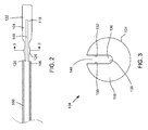
- Fig. 2 shows a side view of the collet 104 decoupled from the proximal end 106 of the tubular member 108.
- the collet 104 may further include a gap or slit 148 that longitudinally extends in the collet body 118.
- the slit 148 may extend from the proximal portion 120 to a position in the distal portion 122 that is proximal the distal end 146.
- a length of the slit 148 may be in a range of about 75 percent to 80 percent a total length of the collet 104, although other lengths may be used.
- the slit 148 may extend in the collet body 118 from the outer surface 124 to the inner surface 138 (shown in Fig. 3 ).
- the slit 148 may enable the collet body 118 to flex or move between an unbiased position and a biased position.
- the collet body 118 may be in the unbiased position when decoupled to the distal end 106 of the tubular member 108.
- the collet body 118 may be in the biased position when coupled and press fit to the distal end 106.
- Fig. 3 shows a cross-sectional, axial view of the collet 104 taken along line 3-3 in Fig. 2 .
- the width of the slit 148 which may be defined by a distance between opposing side walls 150, 152 of the collet body 118 formed by the slit 148 may be at a maximum.
- a cross-sectional area of the central lumen 136 i.e., a cross-sectional area defined by the inner surface 138 of the collet body 118
- a cross-sectional area of the central lumen 136 i.e., a cross-sectional area defined by the inner surface 138 of the collet body 118
- the inner surface 126 of the tubular member 108 may exert an inward bias on the outer surface 124 of the collet body 118, which may cause the slit 148 to close or be in a closed or substantially closed position-i.e., the press fit may cause the width of the slit 148 to decrease and the side walls 150, 152 of the collet body 118 separated by the slit 148 to move closer to each other.
- the inner surface 138 may move inward or contract, which may decrease the cross-sectional area of the central lumen 136.
- the resultant cross-sectional area of the central lumen 136 when the collet 104 is press fit to the tubular member 108 may be dimensioned relative and/or proportional to the diameter of the cutting wire 114 such that a frictional force between the inner surface 138 and the cutting wire 114 is created when the cutting wire 138 is inserted and/or moved within the central lumen 136.
- the frictional force may a value or within a range that is less than a longitudinal force exerted on the cutting wire 114 by the control mechanism 140, while greater than a maximum or worst-case external force to cause longitudinal movement of the cutting wire 114 relative to the tubular member 108.
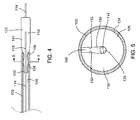
- Fig. 5 shows a cross-sectional, axial view of the collet 104 press fit to the tubular member 108, taken along line 5-5 in Fig. 4 .
- the inward force exerted on the outer surface 124 by inner surface 126 of the tubular member 108 may cause the side walls 150, 152 to move closer to each other and the inner surface 138 to contract, thereby decreasing the cross-sectional area of the central lumen 136.
- the resultant cross-sectional area may be dimensioned relative and/or proportional to the diameter of the cutting wire 114 so that a frictional force is created between the inner surface 138 and the cutting wire 114.
- the cutting wire lumen 112 and the central lumen 136 and/or the slit 148 may be used as a flushing channel or lumen to send liquid or fluid to the treatment site, in addition to being used as a channel to advance and retract the cutting wire 114.
- a space defined by the central lumen 136 and/or the slit 148 that is unoccupied by the cutting wire 114 may be sufficient for the fluid to pass to the treatment site while still providing sufficient resistance against longitudinal movement of the cutting wire 114 due to external forces.
- the fluid may be passed through the cutting wire lumen 112 and the central lumen 112, and around or over the cutting wire 114 to the treatment site.
- the cutting wire 114 may occupy about 25 percent of the space or potential area within the collet body 118 for the fluid to pass.
- the tubular member 108 with the collet 104 coupled (e.g., press fit) to the distal end 106 may be distally advanced to a treatment site within a patient, such as by being moved through a working channel of an endoscope (not shown).
- the cutting wire 114 may be disposed within the cutting wire lumen 112 of the tubular member 108.
- the distal end of the cutting wire 114 may be disposed within the central lumen 136 of the collet 104, or alternatively may be disposed at a location proximal the collet 104 within the cutting wire lumen 112.
- the tubular member 108 and the collet 104 may be advanced to a location near the treatment site that is visible by a camera of the endoscope (now shown).
- the cutting wire 114 may then be distally moved relative to the tubular member 108 using the control mechanism 140.
- the distal end of the cutting wire 114 may be moved through the cutting wire lumen 112 and through the central lumen 136 of the collet 104 to a desired location that is exposed outside of and distal to the distal end 146 of the collet 104.
- the tubular member 108, the collet 108, and the cutting wire 114 may further be distally advanced so that the distal end of the cutting wire 114, now exposed, makes contact with tissue at the treatment site.
- the electrosurgical procedure may be performed on the tissue.
- the power source 116 may be activated, which may send electrical current along the cutting wire 114, through the tissue at the treatment site, and then along a return path back to the currents source 116.
- the endoscopic needle knife 102 has a bipolar configuration
- the electrical current after passing through the tissue, may pass through the collet body 118, which may be part of the return path.
- the collet 104 may not be part of the return path, and the electrical current may pass through a return path that is outside of the patient.
- the cutting wire 114 may be resistant to these external forces due to the frictional force created by the collet 104 on the cutting wire 114. As a result, the cutting wire 114 may remain in the desired location outside of the collet 104 in the presence of the external forces when the electrosurgical procedure is being performed.
- the power source 116 may be deactivated, and the distal end of the cutting wire 114 may be retracted back into the central lumen 114 and the cutting wire lumen 112 using the control mechanism 140.
- the tubular member 108, along with the collet 104 and the cutting wire 114, may then be removed from the patient.
- the collet 104 may be made of various materials and/or be sized to have various dimensions.
- the collet 104 may be made of stainless steel, particularly for an endoscopic needle knife 102 having a bipolar configuration, although other materials, including conductive or non-conductive materials, may be used.
- a metal other than stainless steel may be used, which may have a lower resistivity and/or better conduction than stainless steel.
- the dimensions of the collet 104 may be dependent on the type of endoscopic needle knife 102, the catheter 108, the cutting wire 114, and/or their respective dimensions.
- a total length of the collet 104 may be about 11 mm (0.46 inches); a length of the proximal portion 120 may be about 5 mm (0.18 inches), and a length of the distal portion 122 may be 7 mm (0.28 inches).
- a largest diameter at the protruding portion 128 may be about 1 mm (0.045 inches), and a largest diameter of the distal portion 122 may be about 1 mm (0.045 inches).
- the outer diameter of the protruding portion 128 and the width of the slit 148 may be dimensioned dependently of each other to obtain a desired frictional force and/or a desired press fit.
- the width of the slit 148 may be dependent on the insulative material, such as PTFE heath shrink, covering the conductive portion of the cutting wire 114.
- the width of the slit 148 and/or the size of the central lumen 138 may be sized to be about the same size as or slightly larger than the diameter of the cutting wire 114 when the collet 104 is decoupled from the distal end 106 of the tubular member 108. Then, when the collet 104 is press fit to the tubular member, the space within the central lumen 138 contracts to achieve the desired amount of frictional force.
- collet 104 described above with reference to Figures 1-5 is described as having a central lumen 138 that is concentric with a single cutting wire lumen 112 when the collet 104 is coupled to a tubular member 108.
- the collet 104 may alternatively be adapted to be coupled a tubular member 108 where the cutting wire lumen 112 is one of multiple lumens extending within the tubular member 108.
- the dimensions of the collet 104 may be adapted accordingly.
- the collet 104 may be considered a component of the endoscopic needle knife 102, or alternatively may be considered a component that is separate from and/or that is used with an endoscopic needle knife 102.
- the endoscopic needle knife 102 may be manufactured to include and/or be delivered to an end user, operator, or purchaser, with the collet 104 coupled to the tubular member 108.
- the collet 104 may be a standalone component that is manufactured separate from and/or separately delivered to an end user or purchaser of the endoscopic needle knife 102.
- the collet 104 may be a replaceable component.
- the collet 104 may be replaced with a different collet.
- the same collet may be used with different endoscopic needle knives, or with the same needle knife at different times or during different procedures.
- Various configurations are possible.
- the collet 104 may be coupled to a distal end of an elongate tubular member of a medical device other than an endoscopic needle knife.
- the collet 104 may be configured to receive and exert an inward force on an elongate inner member longitudinally disposed and movable within a tubular member other than a cutting wire.
- An example medical device having such an elongate inner member may include an injection needle having a needle that, when distally advanced past a distal end of a tubular member, is received by the collet 104.
- Other elongate inner members may include a wire guide, a stylet, or an inner tubular member, such as an inner catheter, as examples.
Landscapes
- Health & Medical Sciences (AREA)
- Surgery (AREA)
- Life Sciences & Earth Sciences (AREA)
- Engineering & Computer Science (AREA)
- Heart & Thoracic Surgery (AREA)
- Animal Behavior & Ethology (AREA)
- Veterinary Medicine (AREA)
- Public Health (AREA)
- General Health & Medical Sciences (AREA)
- Biomedical Technology (AREA)
- Nuclear Medicine, Radiotherapy & Molecular Imaging (AREA)
- Medical Informatics (AREA)
- Molecular Biology (AREA)
- Physics & Mathematics (AREA)
- Plasma & Fusion (AREA)
- Otolaryngology (AREA)
- Cardiology (AREA)
- Oral & Maxillofacial Surgery (AREA)
- Pathology (AREA)
- Surgical Instruments (AREA)
- Endoscopes (AREA)
Abstract
Description
- The present invention relates generally to medical devices, and more particularly to a collet coupled to a catheter of an endoscopic needle knife.
- Endoscopic needle knives may be used to perform various electrosurgical medical procedures, such as endoscopic submucosal dissection (ESD) or endoscopic retrograde cholangiopancreatography (ERCP) on tissue within a patient. An endoscopic needle knife may be used as an alternative to a sphincterotome, particularly where the sphincterotome is unable to cannulate the papilla. The endoscopic needle knife may include a cutting wire disposed within a catheter. The cutting wire may be moved so that a distal end of the cutting wire distally extends past the catheter to a desired location. The distal end of the cutting wire may contact the tissue, and an electrical current may be sent along the cutting wire to perform the electrical procedure.
- During operation of the endoscopic needle knife, various forces may be exerted on the endoscopic needle knife that may cause longitudinal movement of the cutting wire relative to the tubular member. For example, forces due to hysteresis as the needle knife moves between tortuous to straight positions within a working channel of the endoscope may cause the cutting wire to move. Additionally, the cutting wire may move when the distal end comes into contact with the tissue at the treatment site. Consequently, the distal end of the cutting wire may move or be displaced from its desired location, and the amount of cutting wire exposed at the distal end may uncontrollably vary.
- An aspect of the present disclosure may include an endoscopic needle knife configured to perform an electrosurgical procedure at a treatment site within a patient. The endoscopic needle knife may include a cutting wire configured to conduct an electrical current to perform the electrosurgical procedure. The endoscopic needle knife may also include an elongate tubular member and a cutting wire lumen longitudinally extending through the tubular member and configured to receive the cutting wire. Additionally, a collet may be coupled to a distal end of the tubular member. The collet may include a collet body and a central lumen longitudinally extending through the collet body and configured to receive the cutting wire. The collet body may include an inner surface defined by the central lumen. The inner surface may exert an inward force on the cutting wire when the cutting wire is disposed within the central lumen of the collet.
- Another aspect of the present disclosure may include a collet coupled to a catheter of an endoscopic needle knife. The collet may include a collet body that has a proximal portion configured to be coupled to a distal end of a tubular member of the endoscopic needle knife. The collet may also have a central lumen longitudinally extending through the collet body. The central lumen may be sized to have a cutting wire of the endoscopic needle knife movably disposed therein. An inner surface of the collet body may be defined by the central lumen. The inner surface may create a frictional force with the cutting wire when the proximal portion is coupled to the distal end of the tubular member. The frictional force may prevent longitudinal movement of the cutting wire caused by one or more external forces during operation of the endoscopic needle knife. Additionally, the collet may include a slit longitudinally disposed through the collet body. The slit may be in a closed position when the proximal portion of the collet body is coupled to the distal end of the tubular member.
- A further aspect of the present disclosure may include a medical system that includes an endoscopic needle knife and a power source electrically coupled to the endoscopic needle knife to deliver electrical current to the endoscopic needle knife for performance of an electrosurgical procedure. The endoscopic needle knife may include an elongate tubular member, a cutting wire lumen longitudinally extending through the tubular member, and a collet coupled to a distal end of the tubular member. The collet may include a collet body and a central lumen longitudinally extending through the collet body. The collet body may include an inner surface defined by the central lumen. The endoscopic needle knife may also include a cutting wire that receives the electrical current from the power source to perform the electrosurgical procedure. The cutting wire may be disposed within the cutting wire lumen and the central lumen of the collet. Further, the endoscopic needle knife may include a handle assembly that has a control mechanism operatively coupled with the cutting wire to longitudinally move the cutting wire relative to the tubular member. The inner surface of the collet body may exert an inward force on the cutting wire to create a frictional force between the cutting wire and the inner surface. The frictional force may be greater than longitudinal external forces exerted on the cutting wire during operation of the endoscopic needle knife, and less than a longitudinal force exerted on the cutting wire by the control mechanism.
-
-
FIG. 1 shows a partial cross-sectional side view of an electrosurgicalmedical system 100 that includes an endoscopic needle knife having a collet. -
FIG. 2 shows a side view of the collet ofFIG. 1 decoupled from a distal end of a tubular member of the endoscopic needle knife. -
FIG. 3 shows a cross-sectional, axial view of the collet taken along line 3-3 inFIG. 2 . -
FIG. 4 shows a side view of the collet ofFIG. 1 coupled to the distal end of the tubular member of the endoscopic needle knife. -
FIG. 5 shows a cross-sectional, axial view of the collet taken along line 5-5 inFIG. 4 . - The present disclosure describes an endoscopic needle knife configured to perform an electrosurgical procedure that includes a collet coupled to a distal end of a catheter. To perform the electrosurgical procedure, a cutting wire may be advanced through the catheter and then through the collet, where a distal end of the cutting wire may be exposed. While the cutting wire is disposed within the collet, the collet may exert an inward force on the cutting wire, creating a frictional force that provides resistance to longitudinal movement of the cutting wire at the distal end.
- The cutting wire may be subjected to external forces that longitudinally bias the cutting wire relative to the catheter. The external forces may include hysteretic forces or forces due to hysteresis created from movement of the catheter and cutting wire through a tortuous path within a patient. In addition or alternatively, the external forces may include forces created when the cutting wire makes contact with tissue at a treatment site within the patient. The collet may be coupled to the distal end of the catheter to prevent longitudinal movement of the cutting wire relative to the catheter caused by external forces. To prevent longitudinal movement caused by external forces, the frictional force created by the collet may be greater than a worst-case or maximum external force.
- While preventing longitudinal movement of the cutting wire caused by external forces, the collet may permit longitudinal movement of the cutting wire due to a longitudinal force exerted on the cutting wire by a control mechanism of the needle knife that advances and retracts the cutting wire relative to the catheter. To permit movement of the cutting wire due to the control mechanism, the frictional force created by the collet may be less than the longitudinal force exerted on the cutting wire by the control mechanism. In this way, the collet may provide a frictional force that allows an operator to move the cutting wire to a desired position without external forces displacing the cutting wire away from the desired position during movement or operation of the needle knife.
- The collet may be used with an endoscopic needle knife that has a monopolar configuration or a bipolar configuration. Where the needle knife has a bipolar configuration, the collet may part of a return path for electrical current used to perform the electrosurgical procedure.
-
FIG. 1 shows a partial cross-sectional side view of an electrosurgicalmedical system 100 that includes anendoscopic needle knife 102 having acollet 104 coupled to adistal end 106 of an elongatetubular member 108. Acutting wire lumen 112 may longitudinally extend within thetubular member 108 from aproximal end 110 to thedistal end 106 of thetubular member 108. In some example embodiments, thecutting wire lumen 112 may be centrally disposed within thetubular member 108. Thecutting wire lumen 112 may be configured to receive and have movably disposed within it acutting wire 114 that may be configured to perform an electrosurgical procedure, such as ESD or ERCP. Thecutting wire 114 may include a conductive portion made of a conductive material, such as stainless steel or tungsten, as examples. The conductive portion may be coated or encased in an insulating material, such as a Parylene coating or polytetrafluoroethylene (PTFE) heat shrink, except at a distal tip. In some examples, the distal tip may be about one millimeter in length. Thecutting wire 114 may be electrically coupled to apower source 116, such as an electrosurgical unit (ESU), that supplies electrical current to thecutting wire 114 to perform the electrosurgical procedure. For some exampleendoscopic needle knives 102, thepower source 116 may be operatively coupled to thecutting wire 114 through ahandle assembly 142, as shown inFig. 1 , although other configurations are possible. - The
collet 104 may include acollet body 118 having aproximal portion 120 and adistal portion 122. Thecollet 104 may be coupled to thedistal end 106 of thetubular member 108 through a press fit or frictional fit between anouter surface 124 of theproximal portion 120 and aninner surface 126 of thetubular member 108. Theinner surface 126 may be defined or determined by thecutting wire lumen 112. In one example embodiment, theproximal portion 120 may include a protrudingportion 128 that may be press fit to theinner surface 126. The protrudingportion 128 may include an area of theproximal portion 120 having the largest outer diameter of theproximal portion 120. The largest outer diameter of theproximal portion 120 may be greater than a diameter of thecutting wire lumen 112 at thedistal end 106 to create the press fit. As shown inFig. 1 , the protrudingportion 128 may be a rounded, spherical, or ball-like structure. In alternative example embodiments, theproximal portion 120 may include multiple protruding portions, and/or shaped structures other than rounded, spherical, or ball-like to create the press fit between theouter surface 124 of theproximal portion 120 of thecollet 104 and theinner surface 126 of thetubular member 108. - A
distal end 130 of theproximal portion 120 of thecollet body 118 may include a tapered portion that may serve or function as a transition between theproximal portion 120 and thedistal portion 122. The taperedportion 130 may taper proximally such that the outer diameter of thecollet body 118 may distally increase or expand to a size that is greater than the diameter of thecutting wire lumen 112. In this way, the taperedportion 130 may provide a stop at which point thecollet 104 may not further extend in thecutting wire lumen 112. - In the example embodiment of the
collet 104 shown inFig. 1 , thedistal portion 122 may be a portion of thecollet body 118 that may be disposed outside of and distal to thetubular member 108 and/or the portion of thecollet body 118 that is not press fit to theinner surface 126 of thetubular member 108. Thedistal portion 122 may have an outer diameter that is greater than the diameter of thecutting wire lumen 112, as well as the outer diameters of theproximal portion 120 of thecollet body 118. In an alternative example embodiment of thecollet 104, both theproximal portion 120 and thedistal portion 122 of thecollet body 118 may be disposed within thecutting wire lumen 112 when thecollet 104 is coupled and press fit to thedistal end 106 of thetubular member 108. - Additionally, in the example embodiment of the
collet 104 shown inFig. 1 , thedistal portion 122 may include aproximal end 132 that includes a tapered portion. Some exampleendoscopic needle knives 102 may include anouter sheath 134 that longitudinally extends over thetubular member 108. The taperedportion 132 may have an outer diameter that distally increases from a size that is smaller than an inner diameter of theouter sheath 134 to a size that is larger than the inner diameter of theouter sheath 134. In this way, theouter sheath 134 may extend over at least a portion of theproximal end 134, but may not extend over the entiredistal portion 122 of thecollet body 118. In alternative example embodiments, thedistal portion 122 of thecollet body 118 may be disposed entirely or at least mostly within theouter sheath 134. In other alternative example embodiments, theproximal end 132 may not be tapered, and/or theendoscopic needle knife 102 may not include anouter sheath 134. Various configurations are possible. - The
collet 104 may further include acentral lumen 136 that may longitudinally extend within thecollet body 118 from theproximal portion 120 to thedistal portion 122. When thecollet 104 is coupled to thedistal end 106 of thetubular member 108, thecentral lumen 136 may be concentric or substantially concentric with thecutting wire lumen 112 of thetubular member 112. Thecentral lumen 136 may determine or define an inner surface 138 (shown inFig. 3 ) of thecollet body 118. - The
central lumen 136 may be configured to receive and/or have thecutting wire 114 disposed within. When theproximal portion 120 is press fit to theinner surface 126 of thetubular member 108 and thecutting wire 114 is disposed in the central lumen 136 (as shown inFig. 1 ), theinner surface 138 may pinch thecutting wire 114 and/or exert an inward force on thecutting wire 114, which may create a frictional force that provides resistance to longitudinal movement of thecutting wire 114 within thecentral lumen 136 of thecollet 104. As previously described, the frictional force created by the collet may be greater than a maximum or worst-case external longitudinal force exerted on thecutting wire 114. By creating a frictional force that is greater than a maximum or worst-case external force, thecollet 104 may prevent undesirable movement away from a desired position or location of thecutting wire 114 caused by an external force on thecutting wire 114. - The
endoscopic needle knife 102 may further include acontrol mechanism 140 that may be operably coupled to thecutting wire 114 to longitudinally move thecutting wire 114 relative to thetubular member 108. In some example configurations, as shown inFig. 1 , thecontrol mechanism 140 may be part of ahandle assembly 142, although thecontrol mechanism 140 may be separate from thehandle assembly 142 in alternative configurations. Thecontrol mechanism 140 may be configured to longitudinally move thecutting wire 114 within thecutting wire lumen 112 and within thecentral lumen 136 of thecollet 104. - The
control mechanism 140 may be configured to move thecutting wire 114 in various ways. For example, the control mechanism 140 (such as the one shown inFig. 1 ) may be configured to move longitudinally, such as by use of a slidable configuration, to move thecutting wire 114. Alternatively, rotational movement of thecontrol mechanism 140, such by use of a threaded configuration, may longitudinally move thecutting wire 114. In addition or alternatively, thecontrol mechanism 140 may include or be connected to one or more electronic devices (not shown) to move thecutting wire 114. Various configurations of thecontrol mechanism 140, other than the configuration shown inFig. 1 , are possible. - To longitudinally move the
cutting wire 114 when thecutting wire 114 is within thecentral lumen 136, either proximally or distally, thecontrol mechanism 140 may exert a longitudinal force on thecutting wire 114 that is greater than the frictional force created by thecollet 104. While creating a frictional force that is greater than a maximum or worst-case external force and less than the longitudinal force exerted on thecutting wire 114 by thecontrol mechanism 140, thecollet 104 may permit thecontrol mechanism 140 to operate to longitudinally move thecutting wire 114 to a desired location or position without external forces moving the cutting wire away from the desired location or position. - The
collet 104 may further include a ring orcannula 144 that may be disposed within thecentral lumen 136 at adistal end 146 of thecollet 104. Thecannula 144 may be included at thedistal end 146 to enhance or maintain stability and/or concentricity of thecutting wire 114 at thedistal end 146 of thecollet 104. Additionally, thecannula 144 may be made of an insulative or dielectric material, such as polytetrafluoroethylene (PTFE) or polyimide (PI) as examples. In some example configurations, thecollet body 118 may be made of a conductive material and, in addition, may be part of a return path for a bipolar configuration of theendoscopic needle knife 102. As previously described, thecutting wire 114 may be coated with an insulative material except at a distal tip, where the conductive portion of thecutting wire 114 may be exposed in order to perform the electrosurgical procedure. Thecannula 144, made of an insulative or dielectric material, may be included at thedistal end 146 to provide separation between thecutting wire 114 and thecollet body 118 in order to prevent possible shorting between the cutting wire 114 (i.e., the active path) and the collet body 118 (i.e., the return path). -
Fig. 2 shows a side view of thecollet 104 decoupled from theproximal end 106 of thetubular member 108. As shown inFig. 2 , thecollet 104 may further include a gap or slit 148 that longitudinally extends in thecollet body 118. Theslit 148 may extend from theproximal portion 120 to a position in thedistal portion 122 that is proximal thedistal end 146. In some example embodiments, a length of theslit 148 may be in a range of about 75 percent to 80 percent a total length of thecollet 104, although other lengths may be used. Additionally, theslit 148 may extend in thecollet body 118 from theouter surface 124 to the inner surface 138 (shown inFig. 3 ). - The
slit 148 may enable thecollet body 118 to flex or move between an unbiased position and a biased position. Thecollet body 118 may be in the unbiased position when decoupled to thedistal end 106 of thetubular member 108. Thecollet body 118 may be in the biased position when coupled and press fit to thedistal end 106. -
Fig. 3 shows a cross-sectional, axial view of thecollet 104 taken along line 3-3 inFig. 2 . When thecollet body 118 is in the unbiased position, the width of theslit 148, which may be defined by a distance between opposingside walls collet body 118 formed by theslit 148 may be at a maximum. In addition or alternatively, when thecollet body 118 is in the unbiased position, a cross-sectional area of the central lumen 136 (i.e., a cross-sectional area defined by theinner surface 138 of the collet body 118) may be at a maximum. - Referring to
Fig. 4 , when thecollet 104 is press fit to thetubular member 108, theinner surface 126 of thetubular member 108 may exert an inward bias on theouter surface 124 of thecollet body 118, which may cause theslit 148 to close or be in a closed or substantially closed position-i.e., the press fit may cause the width of theslit 148 to decrease and theside walls collet body 118 separated by theslit 148 to move closer to each other. As a result, theinner surface 138 may move inward or contract, which may decrease the cross-sectional area of thecentral lumen 136. The resultant cross-sectional area of thecentral lumen 136 when thecollet 104 is press fit to thetubular member 108 may be dimensioned relative and/or proportional to the diameter of thecutting wire 114 such that a frictional force between theinner surface 138 and thecutting wire 114 is created when thecutting wire 138 is inserted and/or moved within thecentral lumen 136. As previously described, the frictional force may a value or within a range that is less than a longitudinal force exerted on thecutting wire 114 by thecontrol mechanism 140, while greater than a maximum or worst-case external force to cause longitudinal movement of thecutting wire 114 relative to thetubular member 108. -
Fig. 5 shows a cross-sectional, axial view of thecollet 104 press fit to thetubular member 108, taken along line 5-5 inFig. 4 . When thecollet 104 is press fit to thetubular member 108, the inward force exerted on theouter surface 124 byinner surface 126 of thetubular member 108 may cause theside walls inner surface 138 to contract, thereby decreasing the cross-sectional area of thecentral lumen 136. The resultant cross-sectional area may be dimensioned relative and/or proportional to the diameter of thecutting wire 114 so that a frictional force is created between theinner surface 138 and thecutting wire 114. - In some example embodiments of the
endoscopic needle knife 102, thecutting wire lumen 112 and thecentral lumen 136 and/or theslit 148 may be used as a flushing channel or lumen to send liquid or fluid to the treatment site, in addition to being used as a channel to advance and retract thecutting wire 114. For these example embodiments, when thecollet 104 is press fit to thetubular member 108, a space defined by thecentral lumen 136 and/or theslit 148 that is unoccupied by thecutting wire 114 may be sufficient for the fluid to pass to the treatment site while still providing sufficient resistance against longitudinal movement of thecutting wire 114 due to external forces. During operation, the fluid may be passed through thecutting wire lumen 112 and thecentral lumen 112, and around or over thecutting wire 114 to the treatment site. In some configurations, thecutting wire 114 may occupy about 25 percent of the space or potential area within thecollet body 118 for the fluid to pass. - The following describes an operation of the
needle knife 102 to perform an electrosurgical procedure with reference toFigs. 1-5 . During operation of theendoscopic needle knife 102, thetubular member 108 with thecollet 104 coupled (e.g., press fit) to thedistal end 106 may be distally advanced to a treatment site within a patient, such as by being moved through a working channel of an endoscope (not shown). While thetubular member 108 and thecollet 104 are being advanced, thecutting wire 114 may be disposed within thecutting wire lumen 112 of thetubular member 108. During advancement, the distal end of thecutting wire 114 may be disposed within thecentral lumen 136 of thecollet 104, or alternatively may be disposed at a location proximal thecollet 104 within thecutting wire lumen 112. - The
tubular member 108 and thecollet 104 may be advanced to a location near the treatment site that is visible by a camera of the endoscope (now shown). Thecutting wire 114 may then be distally moved relative to thetubular member 108 using thecontrol mechanism 140. The distal end of thecutting wire 114 may be moved through thecutting wire lumen 112 and through thecentral lumen 136 of thecollet 104 to a desired location that is exposed outside of and distal to thedistal end 146 of thecollet 104. If necessary, thetubular member 108, thecollet 108, and thecutting wire 114 may further be distally advanced so that the distal end of thecutting wire 114, now exposed, makes contact with tissue at the treatment site. - When the distal end of the
cutting wire 114 is exposed outside of thecollet 104, the electrosurgical procedure may be performed on the tissue. Thepower source 116 may be activated, which may send electrical current along thecutting wire 114, through the tissue at the treatment site, and then along a return path back to thecurrents source 116. Where theendoscopic needle knife 102 has a bipolar configuration, the electrical current, after passing through the tissue, may pass through thecollet body 118, which may be part of the return path. Alternatively, where theendoscopic needle knife 102 has a monopolar configuration, thecollet 104 may not be part of the return path, and the electrical current may pass through a return path that is outside of the patient. - While the
cutting wire 114 is exposed outside of thecollet 104 at a desired location, various forces may be longitudinally exerted on thecutting wire 114, such as forces due to hysteresis caused by movement of thetubular member 108 and/or contact from the tissue at the treatment site. However, thecutting wire 114 may be resistant to these external forces due to the frictional force created by thecollet 104 on thecutting wire 114. As a result, thecutting wire 114 may remain in the desired location outside of thecollet 104 in the presence of the external forces when the electrosurgical procedure is being performed. - After the electrosurgical procedure is performed, the
power source 116 may be deactivated, and the distal end of thecutting wire 114 may be retracted back into thecentral lumen 114 and thecutting wire lumen 112 using thecontrol mechanism 140. Thetubular member 108, along with thecollet 104 and thecutting wire 114, may then be removed from the patient. - The
collet 104 may be made of various materials and/or be sized to have various dimensions. In some example embodiments, thecollet 104 may be made of stainless steel, particularly for anendoscopic needle knife 102 having a bipolar configuration, although other materials, including conductive or non-conductive materials, may be used. For example, a metal other than stainless steel may be used, which may have a lower resistivity and/or better conduction than stainless steel. The dimensions of thecollet 104 may be dependent on the type ofendoscopic needle knife 102, thecatheter 108, thecutting wire 114, and/or their respective dimensions. As non-limiting examples, a total length of thecollet 104 may be about 11 mm (0.46 inches); a length of theproximal portion 120 may be about 5 mm (0.18 inches), and a length of thedistal portion 122 may be 7 mm (0.28 inches). A largest diameter at the protrudingportion 128 may be about 1 mm (0.045 inches), and a largest diameter of thedistal portion 122 may be about 1 mm (0.045 inches). - Additionally, during design of the
collet 104, the outer diameter of the protrudingportion 128 and the width of theslit 148 may be dimensioned dependently of each other to obtain a desired frictional force and/or a desired press fit. In addition or alternatively, the width of theslit 148 may be dependent on the insulative material, such as PTFE heath shrink, covering the conductive portion of thecutting wire 114. For some example embodiments, the width of theslit 148 and/or the size of thecentral lumen 138 may be sized to be about the same size as or slightly larger than the diameter of thecutting wire 114 when thecollet 104 is decoupled from thedistal end 106 of thetubular member 108. Then, when thecollet 104 is press fit to the tubular member, the space within thecentral lumen 138 contracts to achieve the desired amount of frictional force. - Additionally, the
collet 104 described above with reference toFigures 1-5 is described as having acentral lumen 138 that is concentric with a singlecutting wire lumen 112 when thecollet 104 is coupled to atubular member 108. Thecollet 104 may alternatively be adapted to be coupled atubular member 108 where thecutting wire lumen 112 is one of multiple lumens extending within thetubular member 108. The dimensions of thecollet 104 may be adapted accordingly. - Further, the
collet 104 may be considered a component of theendoscopic needle knife 102, or alternatively may be considered a component that is separate from and/or that is used with anendoscopic needle knife 102. For example, theendoscopic needle knife 102 may be manufactured to include and/or be delivered to an end user, operator, or purchaser, with thecollet 104 coupled to thetubular member 108. Alternatively, thecollet 104 may be a standalone component that is manufactured separate from and/or separately delivered to an end user or purchaser of theendoscopic needle knife 102. In some situations, thecollet 104 may be a replaceable component. For example, thecollet 104 may be replaced with a different collet. In addition or alternatively, for some example embodiments of the collet, the same collet may be used with different endoscopic needle knives, or with the same needle knife at different times or during different procedures. Various configurations are possible. - In addition or alternatively, the
collet 104 may be coupled to a distal end of an elongate tubular member of a medical device other than an endoscopic needle knife. In addition or alternatively, thecollet 104 may be configured to receive and exert an inward force on an elongate inner member longitudinally disposed and movable within a tubular member other than a cutting wire. An example medical device having such an elongate inner member may include an injection needle having a needle that, when distally advanced past a distal end of a tubular member, is received by thecollet 104. Other elongate inner members may include a wire guide, a stylet, or an inner tubular member, such as an inner catheter, as examples. - The foregoing description of various embodiments of the invention has been presented for purposes of illustration and description. It is not intended to be exhaustive or to limit the invention to the precise embodiments disclosed. Numerous modifications or variations are possible in light of the above teachings. The embodiments discussed were chosen and described to provide the best illustration of the principles of the invention and its practical application to thereby enable one of ordinary skill in the art to utilize the invention in various embodiments and with various modifications as are suited to the particular use contemplated. All such modifications and variations are within the scope of the invention as determined by the appended claims when interpreted in accordance with the breadth to which they are fairly, legally, and equitably entitled.
Claims (15)
- A medical device comprising:an elongate tubular member;an inner member lumen longitudinally extending through the tubular member;an elongate inner member longitudinally extending and movably disposed in the inner member lumen; anda collet coupled to a distal end of the tubular member, the collet comprising:a collet body; anda central lumen longitudinally extending through the collet body and configured to receive the elongate inner member,wherein the collet body comprises an inner surface defined by the central lumen,andwherein the inner surface of the collet body exerts an inward force on the elongate inner member when the elongate inner member is disposed within the central lumen of the collet.
- The medical device of claim 1, further comprising a control mechanism operatively coupled to the elongate inner member, the control mechanism configured to exert a longitudinal force on the elongate inner member to move the elongate inner member, the longitudinal force being greater than a frictional force between the elongate inner member and the inner surface of the collet body, the frictional force created by the inward force.
- The medical device of claim 2, wherein the frictional force created by the inner surface is greater than a maximum external longitudinal force exerted on the elongate inner member.
- The medical device of claim 3, wherein the maximum external longitudinal force is generated from at least one of: movement of the tubular member within the working channel of the endoscope or contact of the elongate inner member with tissue at the treatment site.
- The medical device of any of claims 1-4, wherein the inner member lumen defines an inner surface of the tubular member, and wherein the collet body comprises a proximal portion that is press fit with the inner surface of the tubular member to couple the collet to the distal end of the tubular member.
- The medical device of claim 5, wherein the proximal portion of the collet body comprises a protruding portion that is press fit with the inner surface of the tubular member.
- The medical device of claim 6, wherein the protruding portion comprises a rounded portion having an outer diameter that is larger than an inner diameter of the tubular member.
- The medical device of any of claims 1-7, wherein the collet comprises a slit longitudinally extending in the collet body, wherein the slit is substantially closed when the collet is coupled to the distal end of the catheter, the inner surface exerting the inward force on the elongate inner member when the slit is substantially closed.
- The medical device of claim 8, wherein a press fit between a proximal portion of the collet body and an inner surface of the tubular member substantially closes the slit.
- The medical device of claim 8, wherein the slit longitudinally extends from a proximal end of the collet to a position proximal a distal end of the collet.
- The medical device of any of claims 1-10, wherein the collet further comprises a cannula disposed in the central lumen at a distal end of the collet.
- The medical device of claim 11, wherein the cannula is made of an insulating material.
- The medical device of any of claims 1-12, wherein the medical device comprises an endoscopic needle knife configured to perform an electrosurgical procedure at a treatment site within a patient, wherein the elongate inner member comprises a cutting wire configured to conduct electrical current to perform the electrosurgical procedure, and wherein the inner member lumen comprises a cutting wire lumen.
- The medical device of claim 13, wherein the endoscopic needle knife comprises a bipolar needle knife, and wherein the collet comprises a part of a return path of the bipolar needle knife.
- The endoscopic needle knife of claim 13, wherein the central lumen of the collet is part of a flushing lumen, wherein during operation of the needle knife, fluid passes through the central lumen and around the cutting wire lumen to the treatment site.
Applications Claiming Priority (1)
| Application Number | Priority Date | Filing Date | Title |
|---|---|---|---|
| US201261745145P | 2012-12-21 | 2012-12-21 |
Publications (2)
| Publication Number | Publication Date |
|---|---|
| EP2745794A1 true EP2745794A1 (en) | 2014-06-25 |
| EP2745794B1 EP2745794B1 (en) | 2019-01-16 |
Family
ID=49885040
Family Applications (1)
| Application Number | Title | Priority Date | Filing Date |
|---|---|---|---|
| EP13199106.9A Active EP2745794B1 (en) | 2012-12-21 | 2013-12-20 | Collet for an endoscopic needle knife |
Country Status (3)
| Country | Link |
|---|---|
| US (1) | US9717556B2 (en) |
| EP (1) | EP2745794B1 (en) |
| JP (1) | JP5820460B2 (en) |
Families Citing this family (1)
| Publication number | Priority date | Publication date | Assignee | Title |
|---|---|---|---|---|
| CN109512505B (en) * | 2018-12-14 | 2023-08-29 | 南微医学科技股份有限公司 | Limiting device and using method thereof |
Citations (5)
| Publication number | Priority date | Publication date | Assignee | Title |
|---|---|---|---|---|
| US20050215853A1 (en) * | 2004-03-24 | 2005-09-29 | Pentax Corporation | Retractable treatment instrument for endoscope |
| US20080114353A1 (en) * | 2006-11-09 | 2008-05-15 | Pentax Corporation | Treatment tool for endoscope |
| JP2010124913A (en) * | 2008-11-26 | 2010-06-10 | Hoya Corp | Treatment instrument for endoscope |
| US20100217073A1 (en) * | 2007-08-29 | 2010-08-26 | Klaus Fischer | Electrosurgical instrument, and an endoscope with a corresponding instrument |
| US20110202007A1 (en) * | 2006-03-20 | 2011-08-18 | Medtronic, Inc. | Slittable or Removable Valves and Apparatus and Methods for Making and Using Them |
Family Cites Families (13)
| Publication number | Priority date | Publication date | Assignee | Title |
|---|---|---|---|---|
| US4708137A (en) | 1985-05-20 | 1987-11-24 | Olympus Optical Co., Ltd. | High-frequency incision device |
| JPH0542166A (en) | 1991-08-20 | 1993-02-23 | Inter Noba Kk | Electrode catherter for high-frequency abrasion |
| US5626577A (en) | 1994-02-28 | 1997-05-06 | Harris; George A. | Manually extendable electrocautery surgical apparatus |
| US6780180B1 (en) * | 1995-06-23 | 2004-08-24 | Gyrus Medical Limited | Electrosurgical instrument |
| US5827280A (en) | 1996-03-19 | 1998-10-27 | Conmed Corporation | Device for locking a protective endoscopic electrode sleeve |
| US6355034B2 (en) | 1996-09-20 | 2002-03-12 | Ioan Cosmescu | Multifunctional telescopic monopolar/bipolar surgical device and method therefor |
| US6395003B1 (en) | 1998-09-08 | 2002-05-28 | Asahi Kogaku Kogyo Kabushiki Kaisha | Drainage tube indwelling device for endoscope |
| US7135018B2 (en) | 2003-09-30 | 2006-11-14 | Ethicon, Inc. | Electrosurgical instrument and method for transecting an organ |
| JP4774272B2 (en) | 2005-10-19 | 2011-09-14 | Hoya株式会社 | Endoscopic high-frequency incision tool |
| US20080122311A1 (en) * | 2006-06-13 | 2008-05-29 | The Board Of Regents, The University Of Texas System | Rotor assembly and method of assembling a rotor of a high speed electric machine |
| JP5111931B2 (en) | 2007-05-07 | 2013-01-09 | オリンパスメディカルシステムズ株式会社 | Endoscopic treatment tool |
| JP2009090003A (en) | 2007-10-11 | 2009-04-30 | Fujinon Corp | High-frequency treatment instrument for endoscope |
| WO2010074153A1 (en) * | 2008-12-24 | 2010-07-01 | オリンパスメディカルシステムズ株式会社 | Treatment instrument |
-
2013
- 2013-12-19 US US14/134,181 patent/US9717556B2/en active Active
- 2013-12-20 JP JP2013264438A patent/JP5820460B2/en active Active
- 2013-12-20 EP EP13199106.9A patent/EP2745794B1/en active Active
Patent Citations (5)
| Publication number | Priority date | Publication date | Assignee | Title |
|---|---|---|---|---|
| US20050215853A1 (en) * | 2004-03-24 | 2005-09-29 | Pentax Corporation | Retractable treatment instrument for endoscope |
| US20110202007A1 (en) * | 2006-03-20 | 2011-08-18 | Medtronic, Inc. | Slittable or Removable Valves and Apparatus and Methods for Making and Using Them |
| US20080114353A1 (en) * | 2006-11-09 | 2008-05-15 | Pentax Corporation | Treatment tool for endoscope |
| US20100217073A1 (en) * | 2007-08-29 | 2010-08-26 | Klaus Fischer | Electrosurgical instrument, and an endoscope with a corresponding instrument |
| JP2010124913A (en) * | 2008-11-26 | 2010-06-10 | Hoya Corp | Treatment instrument for endoscope |
Also Published As
| Publication number | Publication date |
|---|---|
| JP2014128654A (en) | 2014-07-10 |
| US9717556B2 (en) | 2017-08-01 |
| US20140180284A1 (en) | 2014-06-26 |
| JP5820460B2 (en) | 2015-11-24 |
| EP2745794B1 (en) | 2019-01-16 |
Similar Documents
| Publication | Publication Date | Title |
|---|---|---|
| JP7432663B2 (en) | Epicardial access system and method | |
| EP3122416B1 (en) | Medical apparatus for fluid communication | |
| US10363063B2 (en) | Electrosurgical system | |
| US11666377B2 (en) | Electrosurgical device | |
| US9907607B2 (en) | Guide and flexible sleeve for use with catheters | |
| US9888960B2 (en) | Handle and power cord assemblies for bipolar electrosurgical devices | |
| US12161390B2 (en) | Connector system for electrosurgical device | |
| EP3192467B1 (en) | Bipolar sphincterotome | |
| EP2662039B1 (en) | Transseptal needle apparatus | |
| EP2549931B1 (en) | Multiple biopsy device | |
| EP2002858A2 (en) | Single use deflectable stylet | |
| US20180028262A1 (en) | Rf ablation needle | |
| US20130178845A1 (en) | Devices and methods for bipolar and monopolar procedures | |
| US11241268B2 (en) | Electrosurgery devices and methods for providing electric energy treatment | |
| US20150094717A1 (en) | Dome-shaped bipolar electrode assembly | |
| CN113648055A (en) | Ablation catheter, point ablation method and line/ring ablation method | |
| US9717556B2 (en) | Collet for an endoscopic needle knife | |
| CN218075201U (en) | Deep brain electrical stimulation puncture needle | |
| JP5952068B2 (en) | Endoscopic high-frequency treatment instrument | |
| WO2025178013A1 (en) | Electrode catheter |
Legal Events
| Date | Code | Title | Description |
|---|---|---|---|
| PUAI | Public reference made under article 153(3) epc to a published international application that has entered the european phase |
Free format text: ORIGINAL CODE: 0009012 |
|
| 17P | Request for examination filed |
Effective date: 20131220 |
|
| AK | Designated contracting states |
Kind code of ref document: A1 Designated state(s): AL AT BE BG CH CY CZ DE DK EE ES FI FR GB GR HR HU IE IS IT LI LT LU LV MC MK MT NL NO PL PT RO RS SE SI SK SM TR |
|
| AX | Request for extension of the european patent |
Extension state: BA ME |
|
| R17P | Request for examination filed (corrected) |
Effective date: 20141219 |
|
| RBV | Designated contracting states (corrected) |
Designated state(s): AL AT BE BG CH CY CZ DE DK EE ES FI FR GB GR HR HU IE IS IT LI LT LU LV MC MK MT NL NO PL PT RO RS SE SI SK SM TR |
|
| STAA | Information on the status of an ep patent application or granted ep patent |
Free format text: STATUS: EXAMINATION IS IN PROGRESS |
|
| 17Q | First examination report despatched |
Effective date: 20170616 |
|
| RIC1 | Information provided on ipc code assigned before grant |
Ipc: A61B 17/32 20060101ALI20180605BHEP Ipc: A61B 18/14 20060101AFI20180605BHEP Ipc: A61B 10/06 20060101ALI20180605BHEP |
|
| RIC1 | Information provided on ipc code assigned before grant |
Ipc: A61B 18/14 20060101AFI20180611BHEP |
|
| GRAP | Despatch of communication of intention to grant a patent |
Free format text: ORIGINAL CODE: EPIDOSNIGR1 |
|
| STAA | Information on the status of an ep patent application or granted ep patent |
Free format text: STATUS: GRANT OF PATENT IS INTENDED |
|
| INTG | Intention to grant announced |
Effective date: 20180720 |
|
| RIN1 | Information on inventor provided before grant (corrected) |
Inventor name: SIGMON, JR. JOHN CROWDER |
|
| GRAJ | Information related to disapproval of communication of intention to grant by the applicant or resumption of examination proceedings by the epo deleted |
Free format text: ORIGINAL CODE: EPIDOSDIGR1 |
|
| STAA | Information on the status of an ep patent application or granted ep patent |
Free format text: STATUS: EXAMINATION IS IN PROGRESS |
|
| GRAR | Information related to intention to grant a patent recorded |
Free format text: ORIGINAL CODE: EPIDOSNIGR71 |
|
| GRAS | Grant fee paid |
Free format text: ORIGINAL CODE: EPIDOSNIGR3 |
|
| STAA | Information on the status of an ep patent application or granted ep patent |
Free format text: STATUS: GRANT OF PATENT IS INTENDED |
|
| GRAA | (expected) grant |
Free format text: ORIGINAL CODE: 0009210 |
|
| STAA | Information on the status of an ep patent application or granted ep patent |
Free format text: STATUS: THE PATENT HAS BEEN GRANTED |
|
| INTC | Intention to grant announced (deleted) | ||
| INTG | Intention to grant announced |
Effective date: 20181206 |
|
| AK | Designated contracting states |
Kind code of ref document: B1 Designated state(s): AL AT BE BG CH CY CZ DE DK EE ES FI FR GB GR HR HU IE IS IT LI LT LU LV MC MK MT NL NO PL PT RO RS SE SI SK SM TR |
|
| REG | Reference to a national code |
Ref country code: GB Ref legal event code: FG4D |
|
| REG | Reference to a national code |
Ref country code: CH Ref legal event code: EP |
|
| REG | Reference to a national code |
Ref country code: IE Ref legal event code: FG4D |
|
| REG | Reference to a national code |
Ref country code: AT Ref legal event code: REF Ref document number: 1089098 Country of ref document: AT Kind code of ref document: T Effective date: 20190215 |
|
| REG | Reference to a national code |
Ref country code: DE Ref legal event code: R096 Ref document number: 602013049838 Country of ref document: DE |
|
| REG | Reference to a national code |
Ref country code: NL Ref legal event code: MP Effective date: 20190116 |
|
| REG | Reference to a national code |
Ref country code: LT Ref legal event code: MG4D |
|
| PG25 | Lapsed in a contracting state [announced via postgrant information from national office to epo] |
Ref country code: NL Free format text: LAPSE BECAUSE OF FAILURE TO SUBMIT A TRANSLATION OF THE DESCRIPTION OR TO PAY THE FEE WITHIN THE PRESCRIBED TIME-LIMIT Effective date: 20190116 |
|
| REG | Reference to a national code |
Ref country code: AT Ref legal event code: MK05 Ref document number: 1089098 Country of ref document: AT Kind code of ref document: T Effective date: 20190116 |
|
| PG25 | Lapsed in a contracting state [announced via postgrant information from national office to epo] |
Ref country code: PL Free format text: LAPSE BECAUSE OF FAILURE TO SUBMIT A TRANSLATION OF THE DESCRIPTION OR TO PAY THE FEE WITHIN THE PRESCRIBED TIME-LIMIT Effective date: 20190116 Ref country code: LT Free format text: LAPSE BECAUSE OF FAILURE TO SUBMIT A TRANSLATION OF THE DESCRIPTION OR TO PAY THE FEE WITHIN THE PRESCRIBED TIME-LIMIT Effective date: 20190116 Ref country code: ES Free format text: LAPSE BECAUSE OF FAILURE TO SUBMIT A TRANSLATION OF THE DESCRIPTION OR TO PAY THE FEE WITHIN THE PRESCRIBED TIME-LIMIT Effective date: 20190116 Ref country code: FI Free format text: LAPSE BECAUSE OF FAILURE TO SUBMIT A TRANSLATION OF THE DESCRIPTION OR TO PAY THE FEE WITHIN THE PRESCRIBED TIME-LIMIT Effective date: 20190116 Ref country code: NO Free format text: LAPSE BECAUSE OF FAILURE TO SUBMIT A TRANSLATION OF THE DESCRIPTION OR TO PAY THE FEE WITHIN THE PRESCRIBED TIME-LIMIT Effective date: 20190416 Ref country code: PT Free format text: LAPSE BECAUSE OF FAILURE TO SUBMIT A TRANSLATION OF THE DESCRIPTION OR TO PAY THE FEE WITHIN THE PRESCRIBED TIME-LIMIT Effective date: 20190516 Ref country code: SE Free format text: LAPSE BECAUSE OF FAILURE TO SUBMIT A TRANSLATION OF THE DESCRIPTION OR TO PAY THE FEE WITHIN THE PRESCRIBED TIME-LIMIT Effective date: 20190116 |
|
| PG25 | Lapsed in a contracting state [announced via postgrant information from national office to epo] |
Ref country code: BG Free format text: LAPSE BECAUSE OF FAILURE TO SUBMIT A TRANSLATION OF THE DESCRIPTION OR TO PAY THE FEE WITHIN THE PRESCRIBED TIME-LIMIT Effective date: 20190416 Ref country code: GR Free format text: LAPSE BECAUSE OF FAILURE TO SUBMIT A TRANSLATION OF THE DESCRIPTION OR TO PAY THE FEE WITHIN THE PRESCRIBED TIME-LIMIT Effective date: 20190417 Ref country code: LV Free format text: LAPSE BECAUSE OF FAILURE TO SUBMIT A TRANSLATION OF THE DESCRIPTION OR TO PAY THE FEE WITHIN THE PRESCRIBED TIME-LIMIT Effective date: 20190116 Ref country code: IS Free format text: LAPSE BECAUSE OF FAILURE TO SUBMIT A TRANSLATION OF THE DESCRIPTION OR TO PAY THE FEE WITHIN THE PRESCRIBED TIME-LIMIT Effective date: 20190516 Ref country code: RS Free format text: LAPSE BECAUSE OF FAILURE TO SUBMIT A TRANSLATION OF THE DESCRIPTION OR TO PAY THE FEE WITHIN THE PRESCRIBED TIME-LIMIT Effective date: 20190116 Ref country code: HR Free format text: LAPSE BECAUSE OF FAILURE TO SUBMIT A TRANSLATION OF THE DESCRIPTION OR TO PAY THE FEE WITHIN THE PRESCRIBED TIME-LIMIT Effective date: 20190116 |
|
| REG | Reference to a national code |
Ref country code: DE Ref legal event code: R097 Ref document number: 602013049838 Country of ref document: DE |
|
| PG25 | Lapsed in a contracting state [announced via postgrant information from national office to epo] |
Ref country code: CZ Free format text: LAPSE BECAUSE OF FAILURE TO SUBMIT A TRANSLATION OF THE DESCRIPTION OR TO PAY THE FEE WITHIN THE PRESCRIBED TIME-LIMIT Effective date: 20190116 Ref country code: AL Free format text: LAPSE BECAUSE OF FAILURE TO SUBMIT A TRANSLATION OF THE DESCRIPTION OR TO PAY THE FEE WITHIN THE PRESCRIBED TIME-LIMIT Effective date: 20190116 Ref country code: RO Free format text: LAPSE BECAUSE OF FAILURE TO SUBMIT A TRANSLATION OF THE DESCRIPTION OR TO PAY THE FEE WITHIN THE PRESCRIBED TIME-LIMIT Effective date: 20190116 Ref country code: EE Free format text: LAPSE BECAUSE OF FAILURE TO SUBMIT A TRANSLATION OF THE DESCRIPTION OR TO PAY THE FEE WITHIN THE PRESCRIBED TIME-LIMIT Effective date: 20190116 Ref country code: SK Free format text: LAPSE BECAUSE OF FAILURE TO SUBMIT A TRANSLATION OF THE DESCRIPTION OR TO PAY THE FEE WITHIN THE PRESCRIBED TIME-LIMIT Effective date: 20190116 Ref country code: IT Free format text: LAPSE BECAUSE OF FAILURE TO SUBMIT A TRANSLATION OF THE DESCRIPTION OR TO PAY THE FEE WITHIN THE PRESCRIBED TIME-LIMIT Effective date: 20190116 Ref country code: AT Free format text: LAPSE BECAUSE OF FAILURE TO SUBMIT A TRANSLATION OF THE DESCRIPTION OR TO PAY THE FEE WITHIN THE PRESCRIBED TIME-LIMIT Effective date: 20190116 Ref country code: DK Free format text: LAPSE BECAUSE OF FAILURE TO SUBMIT A TRANSLATION OF THE DESCRIPTION OR TO PAY THE FEE WITHIN THE PRESCRIBED TIME-LIMIT Effective date: 20190116 |
|
| PLBE | No opposition filed within time limit |
Free format text: ORIGINAL CODE: 0009261 |
|
| STAA | Information on the status of an ep patent application or granted ep patent |
Free format text: STATUS: NO OPPOSITION FILED WITHIN TIME LIMIT |
|
| PG25 | Lapsed in a contracting state [announced via postgrant information from national office to epo] |
Ref country code: SM Free format text: LAPSE BECAUSE OF FAILURE TO SUBMIT A TRANSLATION OF THE DESCRIPTION OR TO PAY THE FEE WITHIN THE PRESCRIBED TIME-LIMIT Effective date: 20190116 |
|
| 26N | No opposition filed |
Effective date: 20191017 |
|
| PG25 | Lapsed in a contracting state [announced via postgrant information from national office to epo] |
Ref country code: SI Free format text: LAPSE BECAUSE OF FAILURE TO SUBMIT A TRANSLATION OF THE DESCRIPTION OR TO PAY THE FEE WITHIN THE PRESCRIBED TIME-LIMIT Effective date: 20190116 |
|
| PG25 | Lapsed in a contracting state [announced via postgrant information from national office to epo] |
Ref country code: TR Free format text: LAPSE BECAUSE OF FAILURE TO SUBMIT A TRANSLATION OF THE DESCRIPTION OR TO PAY THE FEE WITHIN THE PRESCRIBED TIME-LIMIT Effective date: 20190116 |
|
| REG | Reference to a national code |
Ref country code: CH Ref legal event code: PL |
|
| REG | Reference to a national code |
Ref country code: BE Ref legal event code: MM Effective date: 20191231 |
|
| PG25 | Lapsed in a contracting state [announced via postgrant information from national office to epo] |
Ref country code: MC Free format text: LAPSE BECAUSE OF FAILURE TO SUBMIT A TRANSLATION OF THE DESCRIPTION OR TO PAY THE FEE WITHIN THE PRESCRIBED TIME-LIMIT Effective date: 20190116 |
|
| PG25 | Lapsed in a contracting state [announced via postgrant information from national office to epo] |
Ref country code: LU Free format text: LAPSE BECAUSE OF NON-PAYMENT OF DUE FEES Effective date: 20191220 Ref country code: FR Free format text: LAPSE BECAUSE OF NON-PAYMENT OF DUE FEES Effective date: 20191231 |
|
| PG25 | Lapsed in a contracting state [announced via postgrant information from national office to epo] |
Ref country code: CH Free format text: LAPSE BECAUSE OF NON-PAYMENT OF DUE FEES Effective date: 20191231 Ref country code: BE Free format text: LAPSE BECAUSE OF NON-PAYMENT OF DUE FEES Effective date: 20191231 Ref country code: LI Free format text: LAPSE BECAUSE OF NON-PAYMENT OF DUE FEES Effective date: 20191231 |
|
| PG25 | Lapsed in a contracting state [announced via postgrant information from national office to epo] |
Ref country code: CY Free format text: LAPSE BECAUSE OF FAILURE TO SUBMIT A TRANSLATION OF THE DESCRIPTION OR TO PAY THE FEE WITHIN THE PRESCRIBED TIME-LIMIT Effective date: 20190116 |
|
| PG25 | Lapsed in a contracting state [announced via postgrant information from national office to epo] |
Ref country code: MT Free format text: LAPSE BECAUSE OF FAILURE TO SUBMIT A TRANSLATION OF THE DESCRIPTION OR TO PAY THE FEE WITHIN THE PRESCRIBED TIME-LIMIT Effective date: 20190116 Ref country code: HU Free format text: LAPSE BECAUSE OF FAILURE TO SUBMIT A TRANSLATION OF THE DESCRIPTION OR TO PAY THE FEE WITHIN THE PRESCRIBED TIME-LIMIT; INVALID AB INITIO Effective date: 20131220 |
|
| PG25 | Lapsed in a contracting state [announced via postgrant information from national office to epo] |
Ref country code: MK Free format text: LAPSE BECAUSE OF FAILURE TO SUBMIT A TRANSLATION OF THE DESCRIPTION OR TO PAY THE FEE WITHIN THE PRESCRIBED TIME-LIMIT Effective date: 20190116 |
|
| P01 | Opt-out of the competence of the unified patent court (upc) registered |
Effective date: 20230602 |
|
| PGFP | Annual fee paid to national office [announced via postgrant information from national office to epo] |
Ref country code: GB Payment date: 20251223 Year of fee payment: 13 |
|
| PGFP | Annual fee paid to national office [announced via postgrant information from national office to epo] |
Ref country code: IE Payment date: 20251218 Year of fee payment: 13 |
|
| PGFP | Annual fee paid to national office [announced via postgrant information from national office to epo] |
Ref country code: DE Payment date: 20251229 Year of fee payment: 13 |