EP2745741B1 - A device with a tilt mounting for chair - Google Patents
A device with a tilt mounting for chair Download PDFInfo
- Publication number
- EP2745741B1 EP2745741B1 EP13197030.3A EP13197030A EP2745741B1 EP 2745741 B1 EP2745741 B1 EP 2745741B1 EP 13197030 A EP13197030 A EP 13197030A EP 2745741 B1 EP2745741 B1 EP 2745741B1
- Authority
- EP
- European Patent Office
- Prior art keywords
- tilt
- springs
- chair
- thread
- seat
- Prior art date
- Legal status (The legal status is an assumption and is not a legal conclusion. Google has not performed a legal analysis and makes no representation as to the accuracy of the status listed.)
- Active
Links
Images


Classifications
-
- A—HUMAN NECESSITIES
- A47—FURNITURE; DOMESTIC ARTICLES OR APPLIANCES; COFFEE MILLS; SPICE MILLS; SUCTION CLEANERS IN GENERAL
- A47C—CHAIRS; SOFAS; BEDS
- A47C3/00—Chairs characterised by structural features; Chairs or stools with rotatable or vertically-adjustable seats
- A47C3/02—Rocking chairs
- A47C3/025—Rocking chairs with seat, or seat and back-rest unit, elastically mounted in a rigid frame
- A47C3/026—Rocking chairs with seat, or seat and back-rest unit, elastically mounted in a rigid frame with a central column, e.g. rocking office chairs; Tilting chairs
-
- A—HUMAN NECESSITIES
- A47—FURNITURE; DOMESTIC ARTICLES OR APPLIANCES; COFFEE MILLS; SPICE MILLS; SUCTION CLEANERS IN GENERAL
- A47C—CHAIRS; SOFAS; BEDS
- A47C1/00—Chairs adapted for special purposes
- A47C1/02—Reclining or easy chairs
- A47C1/022—Reclining or easy chairs having independently-adjustable supporting parts
-
- A—HUMAN NECESSITIES
- A47—FURNITURE; DOMESTIC ARTICLES OR APPLIANCES; COFFEE MILLS; SPICE MILLS; SUCTION CLEANERS IN GENERAL
- A47C—CHAIRS; SOFAS; BEDS
- A47C7/00—Parts, details, or accessories of chairs or stools
- A47C7/02—Seat parts
- A47C7/34—Seat parts with springs in compression, e.g. coiled
Definitions
- the present invention relates to a device with a tilt mounting for a chair, wherein the seat of the chair is tiltable forwards and backwards against a spring force from tilt resistance springs, wherein the tilt mounting has an upper part which is attachable to the chair seat and a lower part which is attachable to the undercarriage of the chair and tiltably connected to the upper part, and wherein the tilt resistance is regulated by adjusting the pre-tensioning of the springs. More specifically, the invention relates to a device as specified in the preamble of the independent claim 1.
- an object of the invention is to provide an especially compact and simple construction, which is solved by a device as specified in the characterizing part of the independent claim 1.
- direction indications such as “front”, “rear”, “upper”, “lower”, “upwards”, “downwards”, or similar related to the standing operational position of the chair.
- the mounting will among other of visual and functional considerations and also of safety considerations be in all essentials encased, such that what is visible from the outside is an upper and a lower part of the mounting arranged with a mutual clipping motion and with the necessary operating levers projecting out from the mounting.
- the operating lever for altering the pre-tensioning of the tilt resistance springs is shown, but for other functions of the tilt mounting, normally other operating levers are provided, and a latch lever as shown and described in the applicant's Norwegian patent application No. 20120001538A1 and filed the same day as the present application can especially preferably be provided for locking the mounting in different desired tilt positions and also releasable from these.
- a device with tilt mounting 1 for chair where the seat 2 of the chair is tiltable forwards and backwards against spring force from tilt resistance springs 3, wherein the tilt mounting 1 has an upper part 4 which is attachable to the chair seat 2 and a lower part 5 which is attachable to the undercarriage 6 of the chair and tiltably connected to the upper part 4, and wherein tilt resistance is regulated by adjusting the pre-tensioning of the springs 3, as the distance between an upper spring seat 7 allocated to the upper part 4 and a lower spring seat 8 allocated to the lower part 5 is altered.
- each lower flap-like spring seat 8 is mutually opposite tiltably arranged in proportion to each other for altering said distance, as each lower spring seat 8 is provided with a respective arm or portion 9 projecting up in an operative thread connection with the thread portion 10 of a common rotatable adjusting lever 11, and as the distance between the connection points of the arms 9 along the thread portion 10, and thus the mutually opposite tilt positions of the lower spring seat 8, is altered by rotating the adjustment lever 11.
- the springs 8 are preferably, and as shown, helical springs, but could alternatively be elastomeric blocks.
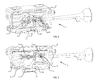
- the two flap-like lower spring seats 8 are preferably provided with respective longitudinal projecting grooves 12 at each lower edge, for tiltable contact with two corresponding longitudinal recessed grooves 13 arranged in parallel in a middle portion 14 projecting up of the lower part 5, as is especially evident from fig. 8 and 9 .
- Each lower flap-like spring seat 8 is preferably provided with a tilt element 15 for contacting a lower part of the spring 3 and to counteract bending of the springs 3 about their longitudinal axis by compensating for altered tilt positions for the lower spring seats 8, as is also especially evident from fig. 8 and 9 .
- connection points for each arm is preferably in the shape of a respective boss 16 turnably attached to each respective arm 9, and provided with respective levelled passing thread openings for guiding through of and thread connection with the thread portion 10 of the adjustment lever 11.
- Each boss 16 is preferably supported between two outer branches of each respective arm 9, and with its turn axis parallel with the tilt axis of the flap-like lower spring seat 8 and normal on the length axis of the adjustment lever.
- the bosses are, as it will also be evident for the person skilled in the art in light of the description and drawings, provided to retain level thread openings in the connection points at the different tilt positions for the lower spring seats 8. Further, it is preferably arranged a stopping pin in an outer end of the thread portion 10 of the adjustment lever 11, as is also evident from fig. 8 and 9 .
- the upper spring seats 7 are preferably provided with a respective substantially conical tapered portion 18 adapted the inner end portion of the helical springs 3, as the substantially conical tapered portion 18 is formed as a recess in the upper part 4.
Landscapes
- Health & Medical Sciences (AREA)
- Dentistry (AREA)
- General Health & Medical Sciences (AREA)
- Chairs Characterized By Structure (AREA)
- Chairs For Special Purposes, Such As Reclining Chairs (AREA)
Description
- The present invention relates to a device with a tilt mounting for a chair, wherein the seat of the chair is tiltable forwards and backwards against a spring force from tilt resistance springs, wherein the tilt mounting has an upper part which is attachable to the chair seat and a lower part which is attachable to the undercarriage of the chair and tiltably connected to the upper part, and wherein the tilt resistance is regulated by adjusting the pre-tensioning of the springs. More specifically, the invention relates to a device as specified in the preamble of the
independent claim 1. - There exist several previously known tilt mountings for chairs, and particularly office chairs, and emphasizing different characteristics and functional controls. As an example of an earlier tilt mounting, reference is made to the mounting shown and described in the applicant's Norwegian patent No.
327014B1 US4744600A . - With basis in the prior art, an object of the invention is to provide an especially compact and simple construction, which is solved by a device as specified in the characterizing part of the
independent claim 1. - Preferred embodiments of the invention are disclosed by the dependent claims.
- A preferred, not limiting embodiment of the invention is further described in the following, with reference to the attached drawings, where
-
fig. 1 is a front perspective view of the device according to the invention, where the tilt mounting is attached to a chair seat and to an upper part of the undercarriage of the chair, -
fig. 2 is a side view corresponding tofig. 1 , -
fig. 3 is a rear view corresponding tofig. 1 , -
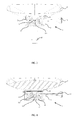
fig. 4 is a cross-sectional view along the line A-A infig. 2 , with the tilt resistance springs of the tilt mounting in a minimal pre-tensioned position, -
fig. 5 is a cross-sectional view along the line B-B infig. 2 , with the tilt resistance springs of the tilt mounting in a minimal pre-tensioned position, -
fig. 6 is a cross-sectional view corresponding tofig. 4 , but with the tilt resistance springs of the tilt mounting in a maximum pre-tensioned position, -
fig. 7 is a cross-sectional view corresponding tofig. 5 , but with the tilt resistance springs of the tilt mounting in a maximum pre-tensioned position, -
fig. 8 is a perspective view of parts of the tilt mounting shown infig. 1 to 7 , and -
fig. 9 is another perspective view of parts of the tilt mounting shown infig. 1 to 7 . - In the description below, direction indications such as "front", "rear", "upper", "lower", "upwards", "downwards", or similar related to the standing operational position of the chair.
- It should further be noticed that even though this is not shown in the figures, and of illustrating considerations, the mounting will among other of visual and functional considerations and also of safety considerations be in all essentials encased, such that what is visible from the outside is an upper and a lower part of the mounting arranged with a mutual clipping motion and with the necessary operating levers projecting out from the mounting. In the figures, only the operating lever for altering the pre-tensioning of the tilt resistance springs is shown, but for other functions of the tilt mounting, normally other operating levers are provided, and a latch lever as shown and described in the applicant's Norwegian patent application No.
20120001538A1 - With reference to the figures, and especially
fig. 1 to 7 , it is according to the invention shown a device with tilt mounting 1 for chair, where theseat 2 of the chair is tiltable forwards and backwards against spring force fromtilt resistance springs 3, wherein the tilt mounting 1 has anupper part 4 which is attachable to thechair seat 2 and alower part 5 which is attachable to the undercarriage 6 of the chair and tiltably connected to theupper part 4, and wherein tilt resistance is regulated by adjusting the pre-tensioning of thesprings 3, as the distance between anupper spring seat 7 allocated to theupper part 4 and alower spring seat 8 allocated to thelower part 5 is altered. This as two lower flap-like spring seats 8 are mutually opposite tiltably arranged in proportion to each other for altering said distance, as eachlower spring seat 8 is provided with a respective arm or portion 9 projecting up in an operative thread connection with thethread portion 10 of a common rotatable adjustinglever 11, and as the distance between the connection points of the arms 9 along thethread portion 10, and thus the mutually opposite tilt positions of thelower spring seat 8, is altered by rotating theadjustment lever 11. - The
springs 8 are preferably, and as shown, helical springs, but could alternatively be elastomeric blocks. - The two flap-like
lower spring seats 8 are preferably provided with respectivelongitudinal projecting grooves 12 at each lower edge, for tiltable contact with two corresponding longitudinalrecessed grooves 13 arranged in parallel in amiddle portion 14 projecting up of thelower part 5, as is especially evident fromfig. 8 and 9 . - Each lower flap-
like spring seat 8 is preferably provided with atilt element 15 for contacting a lower part of thespring 3 and to counteract bending of thesprings 3 about their longitudinal axis by compensating for altered tilt positions for thelower spring seats 8, as is also especially evident fromfig. 8 and 9 . - The connection points for each arm is preferably in the shape of a
respective boss 16 turnably attached to each respective arm 9, and provided with respective levelled passing thread openings for guiding through of and thread connection with thethread portion 10 of theadjustment lever 11. Eachboss 16 is preferably supported between two outer branches of each respective arm 9, and with its turn axis parallel with the tilt axis of the flap-likelower spring seat 8 and normal on the length axis of the adjustment lever. The bosses are, as it will also be evident for the person skilled in the art in light of the description and drawings, provided to retain level thread openings in the connection points at the different tilt positions for thelower spring seats 8. Further, it is preferably arranged a stopping pin in an outer end of thethread portion 10 of theadjustment lever 11, as is also evident fromfig. 8 and 9 . - The
upper spring seats 7 are preferably provided with a respective substantially conicaltapered portion 18 adapted the inner end portion of thehelical springs 3, as the substantially conicaltapered portion 18 is formed as a recess in theupper part 4.
Claims (8)
- A device with a tilt mounting (1) for a chair, wherein the seat (2) of the chair is tiltable forwards and backwards against a spring force from tilt resistance springs (3), where the tilt mounting (1) has an upper part (4) which is attachable to the seat (2) of the chair and a lower part (5) which is attachable to the undercarriage (6) of the chair and tiltably connected to the upper part (4), and where tilt resistance is adjustable by adjustment of the pre-tensioning of the springs (3), wherein the distance between an upper spring seat (7) allocated to the upper part (4) and a lower spring seat (8) allocated to the lower part (5) is altered, characterized in that two lower flap-like spring seats (8) are mutually opposite tiltably arranged relative to each other for altering said distance, wherein each lower spring seat (8) is provided with a respective arm or portion (9) projecting up in an operative thread connection with the thread portion (10) of a common rotatable adjusting lever (11), wherein the distance between the connection points of the arms (9) along the thread portion (10), and thus the mutually opposite tilt positions of the lower spring seat (8), is altered by rotating the adjustment lever (11).
- A device according to claim 1, characterized in that the springs (3) are helical springs or elastomeric blocks.
- A device according to claim 1 or 2, characterized in that the two flap-like lower spring seats (8) are provided with respective longitudinal projecting grooves (12) at each lower edge, for tiltable contact with two corresponding longitudinal recessed grooves (13) arranged in parallel in a middle portion (14) projecting up of the lower part (5).
- A device according to any of the preceding claims 1 to 3, characterized in that each lower flap-like spring seat (8) is provided with a tilt element (15) for contacting a lower part of the spring (3) and to counteract bending of the springs (3) about their longitudinal axis by compensating for altered tilt positions for the lower spring seats (8).
- A device according to any of the preceding claims 1 to 4, characterized in that the connection points for each arm (9) is in the shape of a respective boss (16) turnably attached to each respective arm (9), and provided with respective levelled passing thread openings for guiding through of and thread intervention with the thread portion (10) of the adjustment lever (11).
- A device according to claim 5, characterized in that each respective boss (16) is supported between two outer branches of each respective arm (9), and with its turn axis parallel with the tilt axis of the flap-like lower spring seats (8) and normal on the length axis of the adjustment lever (11).
- A device according to any of the preceding claims 1 to 6, characterized in that a stopping pin (17) is arranged in an outer end of the thread portion (10) of the adjustment lever (11).
- A device according to any of the preceding claims 2 to 7, characterized in that the upper spring seats (7) are provided with a respective substantially conical tapered portion (18) adapted the inner end portion of the helical springs (3), wherein the substantially conical tapered portion (18) is formed as a recess in the upper part (4).
Applications Claiming Priority (1)
| Application Number | Priority Date | Filing Date | Title |
|---|---|---|---|
| NO20121535A NO335007B1 (en) | 2012-12-19 | 2012-12-19 | Device for tilting chair for chair |
Publications (2)
| Publication Number | Publication Date |
|---|---|
| EP2745741A1 EP2745741A1 (en) | 2014-06-25 |
| EP2745741B1 true EP2745741B1 (en) | 2015-08-12 |
Family
ID=49911165
Family Applications (1)
| Application Number | Title | Priority Date | Filing Date |
|---|---|---|---|
| EP13197030.3A Active EP2745741B1 (en) | 2012-12-19 | 2013-12-12 | A device with a tilt mounting for chair |
Country Status (4)
| Country | Link |
|---|---|
| EP (1) | EP2745741B1 (en) |
| KR (1) | KR20140079742A (en) |
| CN (1) | CN103876508B (en) |
| NO (1) | NO335007B1 (en) |
Families Citing this family (3)
| Publication number | Priority date | Publication date | Assignee | Title |
|---|---|---|---|---|
| CN104433387A (en) * | 2014-11-19 | 2015-03-25 | 成都实景信息技术有限公司 | Equipment facilitating work of staffs |
| KR200480729Y1 (en) | 2016-03-29 | 2016-06-29 | 김경훈 | Rehabilitation Patient chair rubber cushioning tilt |
| KR102341830B1 (en) | 2021-10-14 | 2021-12-22 | 주식회사 다원체어스 | Apparatus for setting tilting strength of seat |
Family Cites Families (7)
| Publication number | Priority date | Publication date | Assignee | Title |
|---|---|---|---|---|
| US4744600A (en) * | 1986-05-06 | 1988-05-17 | Itoki Co., Ltd. | Cushioning mechanism for use with seat of chair and interlocking cushioning mechanism for seat and backrest |
| US4889384A (en) * | 1988-07-10 | 1989-12-26 | Leggett & Platt, Incorporated | Knee-action chair control |
| US5375912A (en) * | 1990-08-10 | 1994-12-27 | Stulik; Edward L. | Reclining chair |
| DE4208648C1 (en) * | 1992-03-18 | 1993-05-27 | Roeder Gmbh Sitzmoebelwerke, 6000 Frankfurt, De | |
| JP2003310378A (en) * | 2002-04-22 | 2003-11-05 | Takano Co Ltd | Locking device |
| DE10309922A1 (en) * | 2003-03-07 | 2004-09-16 | Dauphin Entwicklungs- Und Beteiligungs-Gmbh | Chair, especially office chair |
| CN101731861B (en) * | 2009-12-30 | 2012-05-30 | 韩汝辉 | Seat capable of adjusting tilting angle of back |
-
2012
- 2012-12-19 NO NO20121535A patent/NO335007B1/en unknown
-
2013
- 2013-12-12 EP EP13197030.3A patent/EP2745741B1/en active Active
- 2013-12-18 CN CN201310698228.8A patent/CN103876508B/en active Active
- 2013-12-19 KR KR1020130159034A patent/KR20140079742A/en not_active Ceased
Also Published As
| Publication number | Publication date |
|---|---|
| EP2745741A1 (en) | 2014-06-25 |
| CN103876508B (en) | 2018-01-09 |
| NO20121535A1 (en) | 2014-06-20 |
| CN103876508A (en) | 2014-06-25 |
| KR20140079742A (en) | 2014-06-27 |
| NO335007B1 (en) | 2014-08-25 |
Similar Documents
| Publication | Publication Date | Title |
|---|---|---|
| CN108725280B (en) | Armrest module for a motor vehicle seat | |
| KR101426546B1 (en) | Tilting chair | |
| CA2655083C (en) | Constant pressure retreating lumbar system | |
| US6109694A (en) | Chair with four-bar linkage for self-adjusting back tension | |
| US11254247B2 (en) | Lumbar support assembly | |
| JP5613838B2 (en) | Headrest for vehicle seat | |
| US8973994B2 (en) | Variable lumbar support assembly | |
| EP3545795B1 (en) | Forward tilt assembly for chair seat | |
| US8113586B2 (en) | Apparatus for adjusting the seat back angle | |
| US10220738B2 (en) | Suspension device | |
| EP2745741A1 (en) | A device with tilt mounting for chair | |
| CN103957749B (en) | Adjusting mechanism for setting a restoring force which acts on a backrest of a chair, and office chair having an adjusting mechanism of this type | |
| CN107554369B (en) | Suspension device | |
| JP7579045B2 (en) | Chair arm rest device | |
| CN104320994A (en) | Functional chair | |
| GB2593612A (en) | Furniture member having lumbar adjustment mechanism | |
| EP2524623B1 (en) | Chair arrangement | |
| EP2572605B1 (en) | Seat guiding apparatus for chair | |
| EP2874518B1 (en) | A height adjustment device for an armrest | |
| US6102477A (en) | Chair with tilt limiter | |
| JP2008543396A (en) | Guide element, support assembly and corresponding seat structure | |
| NO20073569L (en) | Device for tilting chair for chair | |
| KR20150077502A (en) | Automatic headrest | |
| WO2008055618A1 (en) | Support assembly for a seat | |
| WO2006076966A1 (en) | Support structure for a seat with a table function and corresponding seat suspension arrangement |
Legal Events
| Date | Code | Title | Description |
|---|---|---|---|
| PUAI | Public reference made under article 153(3) epc to a published international application that has entered the european phase |
Free format text: ORIGINAL CODE: 0009012 |
|
| 17P | Request for examination filed |
Effective date: 20131212 |
|
| AK | Designated contracting states |
Kind code of ref document: A1 Designated state(s): AL AT BE BG CH CY CZ DE DK EE ES FI FR GB GR HR HU IE IS IT LI LT LU LV MC MK MT NL NO PL PT RO RS SE SI SK SM TR |
|
| AX | Request for extension of the european patent |
Extension state: BA ME |
|
| REG | Reference to a national code |
Ref country code: DE Ref legal event code: R079 Ref document number: 602013002630 Country of ref document: DE Free format text: PREVIOUS MAIN CLASS: A47C0003026000 Ipc: A47C0001032000 |
|
| GRAP | Despatch of communication of intention to grant a patent |
Free format text: ORIGINAL CODE: EPIDOSNIGR1 |
|
| R17P | Request for examination filed (corrected) |
Effective date: 20141222 |
|
| RBV | Designated contracting states (corrected) |
Designated state(s): AL AT BE BG CH CY CZ DE DK EE ES FI FR GB GR HR HU IE IS IT LI LT LU LV MC MK MT NL NO PL PT RO RS SE SI SK SM TR |
|
| INTG | Intention to grant announced |
Effective date: 20150129 |
|
| RIC1 | Information provided on ipc code assigned before grant |
Ipc: A47C 1/032 20060101AFI20150119BHEP Ipc: A47C 3/026 20060101ALI20150119BHEP |
|
| GRAP | Despatch of communication of intention to grant a patent |
Free format text: ORIGINAL CODE: EPIDOSNIGR1 |
|
| INTG | Intention to grant announced |
Effective date: 20150330 |
|
| GRAS | Grant fee paid |
Free format text: ORIGINAL CODE: EPIDOSNIGR3 |
|
| GRAA | (expected) grant |
Free format text: ORIGINAL CODE: 0009210 |
|
| AK | Designated contracting states |
Kind code of ref document: B1 Designated state(s): AL AT BE BG CH CY CZ DE DK EE ES FI FR GB GR HR HU IE IS IT LI LT LU LV MC MK MT NL NO PL PT RO RS SE SI SK SM TR |
|
| REG | Reference to a national code |
Ref country code: GB Ref legal event code: FG4D |
|
| REG | Reference to a national code |
Ref country code: CH Ref legal event code: EP |
|
| REG | Reference to a national code |
Ref country code: AT Ref legal event code: REF Ref document number: 741346 Country of ref document: AT Kind code of ref document: T Effective date: 20150815 |
|
| REG | Reference to a national code |
Ref country code: IE Ref legal event code: FG4D |
|
| REG | Reference to a national code |
Ref country code: DE Ref legal event code: R096 Ref document number: 602013002630 Country of ref document: DE |
|
| REG | Reference to a national code |
Ref country code: SE Ref legal event code: TRGR |
|
| RAP2 | Party data changed (patent owner data changed or rights of a patent transferred) |
Owner name: SCANDINAVIAN BUSINESS SEATING AB |
|
| REG | Reference to a national code |
Ref country code: LT Ref legal event code: MG4D |
|
| REG | Reference to a national code |
Ref country code: DE Ref legal event code: R082 Ref document number: 602013002630 Country of ref document: DE Representative=s name: VOSSIUS & PARTNER PATENTANWAELTE RECHTSANWAELT, DE Ref country code: DE Ref legal event code: R081 Ref document number: 602013002630 Country of ref document: DE Owner name: SCANDINAVIAN BUSINESS SEATING AB, SE Free format text: FORMER OWNER: SCANDINAVIAN BUSINESS SEATING AS, OSLO, NO |
|
| REG | Reference to a national code |
Ref country code: AT Ref legal event code: MK05 Ref document number: 741346 Country of ref document: AT Kind code of ref document: T Effective date: 20150812 |
|
| REG | Reference to a national code |
Ref country code: NL Ref legal event code: MP Effective date: 20150812 |
|
| PG25 | Lapsed in a contracting state [announced via postgrant information from national office to epo] |
Ref country code: NO Free format text: LAPSE BECAUSE OF FAILURE TO SUBMIT A TRANSLATION OF THE DESCRIPTION OR TO PAY THE FEE WITHIN THE PRESCRIBED TIME-LIMIT Effective date: 20151112 Ref country code: GR Free format text: LAPSE BECAUSE OF FAILURE TO SUBMIT A TRANSLATION OF THE DESCRIPTION OR TO PAY THE FEE WITHIN THE PRESCRIBED TIME-LIMIT Effective date: 20151113 Ref country code: LT Free format text: LAPSE BECAUSE OF FAILURE TO SUBMIT A TRANSLATION OF THE DESCRIPTION OR TO PAY THE FEE WITHIN THE PRESCRIBED TIME-LIMIT Effective date: 20150812 Ref country code: LV Free format text: LAPSE BECAUSE OF FAILURE TO SUBMIT A TRANSLATION OF THE DESCRIPTION OR TO PAY THE FEE WITHIN THE PRESCRIBED TIME-LIMIT Effective date: 20150812 |
|
| REG | Reference to a national code |
Ref country code: GB Ref legal event code: 732E Free format text: REGISTERED BETWEEN 20160128 AND 20160203 |
|
| PG25 | Lapsed in a contracting state [announced via postgrant information from national office to epo] |
Ref country code: ES Free format text: LAPSE BECAUSE OF FAILURE TO SUBMIT A TRANSLATION OF THE DESCRIPTION OR TO PAY THE FEE WITHIN THE PRESCRIBED TIME-LIMIT Effective date: 20150812 Ref country code: IS Free format text: LAPSE BECAUSE OF FAILURE TO SUBMIT A TRANSLATION OF THE DESCRIPTION OR TO PAY THE FEE WITHIN THE PRESCRIBED TIME-LIMIT Effective date: 20151212 Ref country code: AT Free format text: LAPSE BECAUSE OF FAILURE TO SUBMIT A TRANSLATION OF THE DESCRIPTION OR TO PAY THE FEE WITHIN THE PRESCRIBED TIME-LIMIT Effective date: 20150812 Ref country code: RS Free format text: LAPSE BECAUSE OF FAILURE TO SUBMIT A TRANSLATION OF THE DESCRIPTION OR TO PAY THE FEE WITHIN THE PRESCRIBED TIME-LIMIT Effective date: 20150812 Ref country code: PT Free format text: LAPSE BECAUSE OF FAILURE TO SUBMIT A TRANSLATION OF THE DESCRIPTION OR TO PAY THE FEE WITHIN THE PRESCRIBED TIME-LIMIT Effective date: 20151214 Ref country code: PL Free format text: LAPSE BECAUSE OF FAILURE TO SUBMIT A TRANSLATION OF THE DESCRIPTION OR TO PAY THE FEE WITHIN THE PRESCRIBED TIME-LIMIT Effective date: 20150812 Ref country code: HR Free format text: LAPSE BECAUSE OF FAILURE TO SUBMIT A TRANSLATION OF THE DESCRIPTION OR TO PAY THE FEE WITHIN THE PRESCRIBED TIME-LIMIT Effective date: 20150812 |
|
| PG25 | Lapsed in a contracting state [announced via postgrant information from national office to epo] |
Ref country code: NL Free format text: LAPSE BECAUSE OF FAILURE TO SUBMIT A TRANSLATION OF THE DESCRIPTION OR TO PAY THE FEE WITHIN THE PRESCRIBED TIME-LIMIT Effective date: 20150812 |
|
| PG25 | Lapsed in a contracting state [announced via postgrant information from national office to epo] |
Ref country code: SK Free format text: LAPSE BECAUSE OF FAILURE TO SUBMIT A TRANSLATION OF THE DESCRIPTION OR TO PAY THE FEE WITHIN THE PRESCRIBED TIME-LIMIT Effective date: 20150812 Ref country code: DK Free format text: LAPSE BECAUSE OF FAILURE TO SUBMIT A TRANSLATION OF THE DESCRIPTION OR TO PAY THE FEE WITHIN THE PRESCRIBED TIME-LIMIT Effective date: 20150812 Ref country code: EE Free format text: LAPSE BECAUSE OF FAILURE TO SUBMIT A TRANSLATION OF THE DESCRIPTION OR TO PAY THE FEE WITHIN THE PRESCRIBED TIME-LIMIT Effective date: 20150812 Ref country code: CZ Free format text: LAPSE BECAUSE OF FAILURE TO SUBMIT A TRANSLATION OF THE DESCRIPTION OR TO PAY THE FEE WITHIN THE PRESCRIBED TIME-LIMIT Effective date: 20150812 Ref country code: IT Free format text: LAPSE BECAUSE OF FAILURE TO SUBMIT A TRANSLATION OF THE DESCRIPTION OR TO PAY THE FEE WITHIN THE PRESCRIBED TIME-LIMIT Effective date: 20150812 |
|
| REG | Reference to a national code |
Ref country code: DE Ref legal event code: R097 Ref document number: 602013002630 Country of ref document: DE |
|
| PG25 | Lapsed in a contracting state [announced via postgrant information from national office to epo] |
Ref country code: BE Free format text: LAPSE BECAUSE OF NON-PAYMENT OF DUE FEES Effective date: 20151231 Ref country code: RO Free format text: LAPSE BECAUSE OF FAILURE TO SUBMIT A TRANSLATION OF THE DESCRIPTION OR TO PAY THE FEE WITHIN THE PRESCRIBED TIME-LIMIT Effective date: 20150812 |
|
| PLBE | No opposition filed within time limit |
Free format text: ORIGINAL CODE: 0009261 |
|
| STAA | Information on the status of an ep patent application or granted ep patent |
Free format text: STATUS: NO OPPOSITION FILED WITHIN TIME LIMIT |
|
| 26N | No opposition filed |
Effective date: 20160513 |
|
| PG25 | Lapsed in a contracting state [announced via postgrant information from national office to epo] |
Ref country code: LU Free format text: LAPSE BECAUSE OF FAILURE TO SUBMIT A TRANSLATION OF THE DESCRIPTION OR TO PAY THE FEE WITHIN THE PRESCRIBED TIME-LIMIT Effective date: 20151212 Ref country code: MC Free format text: LAPSE BECAUSE OF FAILURE TO SUBMIT A TRANSLATION OF THE DESCRIPTION OR TO PAY THE FEE WITHIN THE PRESCRIBED TIME-LIMIT Effective date: 20150812 |
|
| PG25 | Lapsed in a contracting state [announced via postgrant information from national office to epo] |
Ref country code: SI Free format text: LAPSE BECAUSE OF FAILURE TO SUBMIT A TRANSLATION OF THE DESCRIPTION OR TO PAY THE FEE WITHIN THE PRESCRIBED TIME-LIMIT Effective date: 20150812 |
|
| REG | Reference to a national code |
Ref country code: IE Ref legal event code: MM4A |
|
| REG | Reference to a national code |
Ref country code: FR Ref legal event code: ST Effective date: 20160831 |
|
| PG25 | Lapsed in a contracting state [announced via postgrant information from national office to epo] |
Ref country code: IE Free format text: LAPSE BECAUSE OF NON-PAYMENT OF DUE FEES Effective date: 20151212 |
|
| PG25 | Lapsed in a contracting state [announced via postgrant information from national office to epo] |
Ref country code: FR Free format text: LAPSE BECAUSE OF NON-PAYMENT OF DUE FEES Effective date: 20151231 |
|
| PG25 | Lapsed in a contracting state [announced via postgrant information from national office to epo] |
Ref country code: BE Free format text: LAPSE BECAUSE OF FAILURE TO SUBMIT A TRANSLATION OF THE DESCRIPTION OR TO PAY THE FEE WITHIN THE PRESCRIBED TIME-LIMIT Effective date: 20150812 |
|
| PG25 | Lapsed in a contracting state [announced via postgrant information from national office to epo] |
Ref country code: HU Free format text: LAPSE BECAUSE OF FAILURE TO SUBMIT A TRANSLATION OF THE DESCRIPTION OR TO PAY THE FEE WITHIN THE PRESCRIBED TIME-LIMIT; INVALID AB INITIO Effective date: 20131212 Ref country code: BG Free format text: LAPSE BECAUSE OF FAILURE TO SUBMIT A TRANSLATION OF THE DESCRIPTION OR TO PAY THE FEE WITHIN THE PRESCRIBED TIME-LIMIT Effective date: 20150812 |
|
| PG25 | Lapsed in a contracting state [announced via postgrant information from national office to epo] |
Ref country code: CY Free format text: LAPSE BECAUSE OF FAILURE TO SUBMIT A TRANSLATION OF THE DESCRIPTION OR TO PAY THE FEE WITHIN THE PRESCRIBED TIME-LIMIT Effective date: 20150812 |
|
| REG | Reference to a national code |
Ref country code: CH Ref legal event code: PL |
|
| PG25 | Lapsed in a contracting state [announced via postgrant information from national office to epo] |
Ref country code: MT Free format text: LAPSE BECAUSE OF FAILURE TO SUBMIT A TRANSLATION OF THE DESCRIPTION OR TO PAY THE FEE WITHIN THE PRESCRIBED TIME-LIMIT Effective date: 20150812 |
|
| PG25 | Lapsed in a contracting state [announced via postgrant information from national office to epo] |
Ref country code: CH Free format text: LAPSE BECAUSE OF NON-PAYMENT OF DUE FEES Effective date: 20161231 Ref country code: LI Free format text: LAPSE BECAUSE OF NON-PAYMENT OF DUE FEES Effective date: 20161231 |
|
| PG25 | Lapsed in a contracting state [announced via postgrant information from national office to epo] |
Ref country code: SM Free format text: LAPSE BECAUSE OF FAILURE TO SUBMIT A TRANSLATION OF THE DESCRIPTION OR TO PAY THE FEE WITHIN THE PRESCRIBED TIME-LIMIT Effective date: 20150812 |
|
| PG25 | Lapsed in a contracting state [announced via postgrant information from national office to epo] |
Ref country code: MK Free format text: LAPSE BECAUSE OF FAILURE TO SUBMIT A TRANSLATION OF THE DESCRIPTION OR TO PAY THE FEE WITHIN THE PRESCRIBED TIME-LIMIT Effective date: 20150812 |
|
| PG25 | Lapsed in a contracting state [announced via postgrant information from national office to epo] |
Ref country code: TR Free format text: LAPSE BECAUSE OF FAILURE TO SUBMIT A TRANSLATION OF THE DESCRIPTION OR TO PAY THE FEE WITHIN THE PRESCRIBED TIME-LIMIT Effective date: 20150812 Ref country code: AL Free format text: LAPSE BECAUSE OF FAILURE TO SUBMIT A TRANSLATION OF THE DESCRIPTION OR TO PAY THE FEE WITHIN THE PRESCRIBED TIME-LIMIT Effective date: 20150812 |
|
| P01 | Opt-out of the competence of the unified patent court (upc) registered |
Effective date: 20230526 |
|
| PGFP | Annual fee paid to national office [announced via postgrant information from national office to epo] |
Ref country code: DE Payment date: 20251118 Year of fee payment: 13 |
|
| PGFP | Annual fee paid to national office [announced via postgrant information from national office to epo] |
Ref country code: GB Payment date: 20251016 Year of fee payment: 13 |
|
| PGFP | Annual fee paid to national office [announced via postgrant information from national office to epo] |
Ref country code: FI Payment date: 20251015 Year of fee payment: 13 |
|
| PGFP | Annual fee paid to national office [announced via postgrant information from national office to epo] |
Ref country code: SE Payment date: 20251016 Year of fee payment: 13 |