EP2745738A1 - Rail - Google Patents
Rail Download PDFInfo
- Publication number
- EP2745738A1 EP2745738A1 EP12823852.4A EP12823852A EP2745738A1 EP 2745738 A1 EP2745738 A1 EP 2745738A1 EP 12823852 A EP12823852 A EP 12823852A EP 2745738 A1 EP2745738 A1 EP 2745738A1
- Authority
- EP
- European Patent Office
- Prior art keywords
- section
- drawer
- rail
- seating surface
- ball
- Prior art date
- Legal status (The legal status is an assumption and is not a legal conclusion. Google has not performed a legal analysis and makes no representation as to the accuracy of the status listed.)
- Granted
Links
Images
Classifications
-
- A—HUMAN NECESSITIES
- A47—FURNITURE; DOMESTIC ARTICLES OR APPLIANCES; COFFEE MILLS; SPICE MILLS; SUCTION CLEANERS IN GENERAL
- A47B—TABLES; DESKS; OFFICE FURNITURE; CABINETS; DRAWERS; GENERAL DETAILS OF FURNITURE
- A47B88/00—Drawers for tables, cabinets or like furniture; Guides for drawers
- A47B88/40—Sliding drawers; Slides or guides therefor
- A47B88/483—Sliding drawers; Slides or guides therefor with single extensible guides or parts
- A47B88/487—Sliding drawers; Slides or guides therefor with single extensible guides or parts with rollers, ball bearings, wheels, or the like
-
- A—HUMAN NECESSITIES
- A47—FURNITURE; DOMESTIC ARTICLES OR APPLIANCES; COFFEE MILLS; SPICE MILLS; SUCTION CLEANERS IN GENERAL
- A47B—TABLES; DESKS; OFFICE FURNITURE; CABINETS; DRAWERS; GENERAL DETAILS OF FURNITURE
- A47B88/00—Drawers for tables, cabinets or like furniture; Guides for drawers
- A47B88/40—Sliding drawers; Slides or guides therefor
- A47B88/49—Sliding drawers; Slides or guides therefor with double extensible guides or parts
- A47B88/493—Sliding drawers; Slides or guides therefor with double extensible guides or parts with rollers, ball bearings, wheels, or the like
-
- A—HUMAN NECESSITIES
- A47—FURNITURE; DOMESTIC ARTICLES OR APPLIANCES; COFFEE MILLS; SPICE MILLS; SUCTION CLEANERS IN GENERAL
- A47B—TABLES; DESKS; OFFICE FURNITURE; CABINETS; DRAWERS; GENERAL DETAILS OF FURNITURE
- A47B2210/00—General construction of drawers, guides and guide devices
- A47B2210/0002—Guide construction for drawers
- A47B2210/0029—Guide bearing means
- A47B2210/0032—Balls
-
- A—HUMAN NECESSITIES
- A47—FURNITURE; DOMESTIC ARTICLES OR APPLIANCES; COFFEE MILLS; SPICE MILLS; SUCTION CLEANERS IN GENERAL
- A47B—TABLES; DESKS; OFFICE FURNITURE; CABINETS; DRAWERS; GENERAL DETAILS OF FURNITURE
- A47B2210/00—General construction of drawers, guides and guide devices
- A47B2210/17—Drawers used in connection with household appliances
- A47B2210/175—Refrigerators or freezers
-
- F—MECHANICAL ENGINEERING; LIGHTING; HEATING; WEAPONS; BLASTING
- F25—REFRIGERATION OR COOLING; COMBINED HEATING AND REFRIGERATION SYSTEMS; HEAT PUMP SYSTEMS; MANUFACTURE OR STORAGE OF ICE; LIQUEFACTION SOLIDIFICATION OF GASES
- F25D—REFRIGERATORS; COLD ROOMS; ICE-BOXES; COOLING OR FREEZING APPARATUS NOT OTHERWISE PROVIDED FOR
- F25D23/00—General constructional features
- F25D23/06—Walls
- F25D23/065—Details
- F25D23/067—Supporting elements
-
- F—MECHANICAL ENGINEERING; LIGHTING; HEATING; WEAPONS; BLASTING
- F25—REFRIGERATION OR COOLING; COMBINED HEATING AND REFRIGERATION SYSTEMS; HEAT PUMP SYSTEMS; MANUFACTURE OR STORAGE OF ICE; LIQUEFACTION SOLIDIFICATION OF GASES
- F25D—REFRIGERATORS; COLD ROOMS; ICE-BOXES; COOLING OR FREEZING APPARATUS NOT OTHERWISE PROVIDED FOR
- F25D25/00—Charging, supporting, and discharging the articles to be cooled
- F25D25/02—Charging, supporting, and discharging the articles to be cooled by shelves
- F25D25/024—Slidable shelves
- F25D25/025—Drawers
Definitions
- the present invention relates to a rail installed at a home appliance or furniture having a drawer accommodating space in which a drawer is accommodated and capable of pulling the drawer therefrom and pushing the drawer thereinto.
- a home appliance such as a refrigerator or the like, furniture, or the like, has a drawer for convenient accommodation, and the drawer is pulled out of or pushed into a drawer accommodating section via rails disposed in the drawer accommodating section.
- the rail is a device installed at an object such as a home appliance, furniture, or the like, having a drawer accommodating section so that a drawer is pulled out of or pushed into the drawer accommodating section.
- the rail is configured such that the drawer is pulled out of or pushed into the drawer accommodating section via a fixed rail disposed in the drawer accommodating section provided on the home appliance or furniture and a movable rail installed at the drawer and relatively movable with respect to the fixed rail.
- the rail should be provided to endure a load applied toward a lower portion of the drawer by the weight of the drawer and the weight of matters accommodated in the drawer.
- the rail should have a structure that can support movement of the load according to the pulling-out and pushing-in of the drawer.
- the rail should have a structure prepared for the torsional load.
- the fixed rail and the movable rail may be interfered with each other to make it difficult to pull or push the drawer, or the movable rail and the fixed rail may be deformed to increase a gap between the fixed rail and the movable rail (increase a gap between the drawer and the drawer accommodating section).
- an object of the present invention is to provide a rail having a simple structure and capable of stably supporting a load.
- Another object of the present invention is to provide a rail capable of effectively overcoming a torsional load.
- Still another object of the present invention is to provide a rail capable of preventing interference between components of the rail due to a torsional load.
- the present invention provides a rail installed at an object having a drawer accommodating section in which a drawer is accommodated and configured to pull or push the drawer out of or into the drawer accommodating section, the rail including: a movable rail having an accommodating space formed therein, configured to bring the accommodating space in communication with the outside through an open surface, and fixed to a lower surface of the drawer; a rolling body disposed in the accommodating space and installed at both corners opposite to each other in a diagonal direction of the movable rail; and a fixed rail including a fixing section fixed to the drawer accommodating section, a ball support section disposed in the accommodating space and configured to support the rolling body, and a connecting section having one end connected to the ball support section and the other end pulled out of the accommodating space through the open surface and connected to the fixing section, wherein the connecting section is configured to have an angle within a range from 50 to 70 degrees with respect to the fixing section to prevent interference between the open surface and the connecting section even when the movable rail is pressed by the drawer.
- the rolling body may be constituted by two rows of balls disposed at both corners opposite to each other in a diagonal direction of the movable rail.
- the number of balls installed at each of the ball rows may be varied according to an accommodating volume of the drawer and a width of the drawer.
- the rolling bodies installed at both corners opposite to each other in the diagonal direction of the movable rail may be configured such that a line connecting centers of the rolling bodies has an angle within a range from 40 to 50 degrees with respect to a lower surface of the drawer.
- the fixed rail may be formed by bending one plate member such that the ball support section, the connecting section, and the fixing section are integrally formed.
- the ball support section may further include: a first ball seating surface extending from the connecting section and in which the rolling body, which is disposed at a lower side, of the rolling bodies installed at both corners opposite to each other in the diagonal direction of the movable rail is accommodated; a second ball seating surface in which the rolling body, which is disposed at an upper side, of the rolling bodies installed at both corners opposite to each other in the diagonal direction of the movable rail is accommodated; a bending surface configured to connect the first ball seating surface and the second ball seating surface; and a seating surface supporter having an extension section extending from the second ball seating surface and a bending section formed by bending the extension section and in contact with an upper portion of the connecting section, wherein the first ball seating surface, the bending surface, the second ball seating surface, and the seating surface supporter are configured such that a cross-sectional shape of the ball support section forms a closed curve, and the first ball seating surface and the second ball seating surface are spaced a predetermined distance apart from each other by the extension section.
- the extension section may have an angle within a range from 35 to 55 degrees with respect to the lower surface of the drawer.
- the ball support section may further include a boundary surface disposed between the connecting section and the first ball seating surface to be located at a position at which the lower rolling body is interfered with an imaginary line extending from the connecting section, and formed by bending the first ball seating surface in a direction of the second ball seating surface.
- the bending section may be in contact with the connecting section and disposed on the boundary surface.
- the bending section and the connecting section may be adhered to each other at a partial section of a contact section between the bending section and the connecting section formed in the longitudinal direction of the fixed rail to fix the bending section to the connecting section.
- the movable rails may be installed at both opposite ends of the lower surface of the drawer such that the open surfaces are directed toward comers between the side surfaces and the bottom surface of the drawer accommodating section
- the fixed rails may be configured such that the fixing sections are fixed to both opposite ends of the drawer accommodating section
- the rolling bodies installed at both corners opposite to each other in a diagonal direction of the movable rails may be configured such that a line connecting centers of the rolling bodies has an angle within a range from 40 to 50 degrees with respect to the lower surface of the drawer.
- a rail 100 according to an embodiment of the present invention is installed at an object F such as furniture, a home appliance, or the like, having a drawer accommodating section S in which a drawer D is accommodated.
- the rail 100 includes a movable rail 1 coupled to a lower surface of the drawer D, a fixed rail 7 having one end fixed to a bottom surface or a side surface of the drawer accommodating section S and the other end disposed in the movable rail 1, and a rolling body 3 disposed in the movable rail 1 and supported by the fixed rail 7 to enable movement of the movable rail 1.
- the movable rail 1 includes a frame 11 fixed to a lower surface of the drawer D and having at least one open end of both opposite ends (front and rear surfaces in the drawing).
- An accommodating space 13 in which the rolling body 3 and a ball support section 73 (to be described below) of the fixed rail 7 are accommodated is installed in the frame 11, and the accommodating space 13 is configured to be in communication with the outside of the frame 11 through an open surface 15.
- the movable rail 1 may further include sliding surfaces 17 installed in a longitudinal direction thereof and disposed at an inner circumferential surface of the accommodating space 13 to support the rolling body 3, and the sliding surfaces 17 may be installed at both corners opposite to each other in a diagonal direction of the frame 11, respectively.
- the rolling body 3 includes a lower rolling body 31 disposed at a lower portion of the accommodating space 13 and an upper rolling body 33 disposed at an upper portion in the diagonal direction of the lower rolling body 31, and the plurality of rolling bodies 31 and 33 may be installed in the longitudinal direction of the frame 11.
- a straight line passing through the lower rolling body 31 and the upper rolling body 33 may be inclined with respect to a lower surface of the drawer D by a predetermined angle (see reference character A of FIG. 4 ). Accordingly, when a torsional load (see reference character f2 of FIG. 6 ) is applied to the rail 100 due to the weight of the drawer D and the weight of the accommodated matters, a resistance force of the rail 100 is increased.
- a line connecting centers of the rolling bodies 31 and 33 has a certain angle, in particular, 40 degrees or less, with respect to a bottom surface of the drawer D
- a gap between the upper rolling body 33 and the lower rolling body 31 should be increased in a direction parallel to the bottom surface of the drawer D
- a length of an upper surface of the frame 11 may be increased to be vulnerable to the torsional load.
- the frame 11 may be interfered with the fixed rail 7 (to be described below) when a length (see reference character L2 of FIG. 7 ) of the side surface of the frame 11 is increased and the vertical load, the torsional load, or the side surface external force is applied to the frame 11.
- an angle A formed by the line connecting the centers of the lower rolling body 31 and the upper rolling body 33 and the bottom surface of the drawer D may be set within a range of 40 to 50 degrees, and thus the rail 100 according to the embodiment can have an increased resistance against the vertical load and the torsional load due to the drawer D and the accommodated matters.
- each of the rolling bodies 31 and 33 shown in FIG. 2 is shown as the rolling body 3 having a ball or a spherical shape
- the rolling body installed at the rail 100 according to the embodiment of the present invention may be modified in various shapes different from the shown shape as long as the movable rail 1 is movable by the rolling body.
- the rolling bodies 31 and 33 may be constituted by a pair of ball arrays (not shown) installed in the longitudinal direction of the movable rail 1 and provided at both corners opposite to each other in a diagonal direction of the movable rail 1.
- the number of balls provided in each of the ball arrays (not shown) may be varied according to an accommodating volume of the drawer D and a width of the drawer D.
- the rail 100 may further include a ball retainer (see reference numeral 5 of FIGS. 4 and 5 ) disposed in the accommodating space 13 and in which each of the rolling bodies 31 and 33 is accommodated.
- the ball retainer 5 is configured to maintain a gap between the rolling bodies 31 and 33 in the accommodating space 13 while rotatably supporting the rolling bodies 31 and 33. While the ball retainer 5 may include a retainer frame (not shown) disposed in the accommodating space 13 and an accommodating groove (not shown) provided in the retainer frame (not shown) to accommodate the rolling bodies 31 and 33, the ball retainer 5 may be modified in various types that can implement the above-mentioned functions.
- the fixed rail 7 includes a fixing section 71 fixed to the drawer accommodating section S, the ball support section 73 disposed in the accommodating space 13 to support the rolling body 3, and a connecting section 75 having one end connected to the ball support section 73 and the other end disposed at the outside of the frame 11 and connected to the fixing section 71 via the open surface 15.
- the fixed rail 7 may be configured to include the ball support section 73, the connecting section 75, and the fixing section 71 by folding one plate member.
- the fixing section 71 may be configured to be fixed to the bottom surface of the drawer accommodating section S as shown in FIG. 5 , or may be configured to include a flange 711 configured to fix the fixed rail 7 to a sidewall of the drawer accommodating section S as shown in FIG. 4 .
- the connecting section 75 is configured to be inclined with respect to the fixing section 71 by a predetermined angle B. Accordingly, even when the vertical load or torsional load (see reference character f2 of FIG. 6 ) is applied to the rail 100 by the weight of the drawer D and the weight of the accommodated matters, interference between the movable rail 1 and the fixed rail 7 can be prevented.
- the angle B between the connecting section 75 and the fixing section 71 may be set within a range from 50 to 70 degrees, in particular, 60 degrees.
- the connecting section 75 has an angle larger than 70 degrees with respect to the fixing section 71, since the vertical load and the torsional load are applied to the frame 11, the connecting section 75 and the frame 11 may be interfered with each other to disturb the pulling-out or pushing-in of the drawer D.
- the connecting section 75 has an angle smaller than 50 degrees with respect to the fixing section 71, the frame 11 may come in contact with the bottom surface of the drawer accommodating section S when the vertical load or the torsional load is applied.
- a resistance against the side surface external force (or a side surface collision) applied to the side surface of the drawer D may be increased when the drawer D is pulled out.
- the ball support section 73 may include a first ball seating surface 731 extending from the connecting section 75 and configured to accommodate the lower rolling body 31, a second ball seating surface 733 connected to the first ball seating surface 731 through a bending surface 735 and configured to accommodate the upper rolling body 33, and a seating surface supporter 737 extending from the second ball seating surface 733 and configured to come in contact with the connecting section 75.
- the second ball seating surface 733 is configured to support the upper rolling body 33 to support most of the vertical load of the drawer D and the accommodated matters
- the first ball seating surface 731 is configured to support the lower rolling body 31 to support the torsional load (see reference character f2 of FIG. 6 ) applied to the second ball seating surface 733 and the frame 11.
- first ball seating surface 731 and the connecting section 75 may be connected to each other while forming a boundary surface P.
- the first ball seating surface 731 may be connected to the connecting section 75 and bent in a direction in which the second ball seating surface 733 is formed such that the lower rolling body 31 is disposed at a position interfered with an imaginary line extending from the connecting section 75.
- the seating surface supporter 737 includes an extension section 7371 extending from the second ball seating surface 733 in a direction of the connecting section 75 as a means configured to increase a resistance of the rail 100 when the vertical load and the torsional load caused by the drawer D and the accommodated matters are applied to the rail 100, and a bending section 7373 formed by bending one end of the extension section 7371 and configured to come in contact with an upper portion of the connecting section 75.
- the extension section 7371 may be inclined to have a predetermined angle C within a range from 35 to 55 degrees with respect to the bottom surface of the drawer D, and in particular, the extension section 7371 may have an angle of 45 degrees with respect to the bottom surface of the drawer D (an angle of 45 degrees with respect to the bottom surface of the drawer accommodating section S).
- extension section 7371 is disposed parallel to the bottom surface of the drawer D (an angle of 35 degrees or less) or has an angle of 55 degrees or more, a force applied to the lower rolling body 31 and the upper rolling body 33 cannot be effectively overcome when the vertical load and the torsional load are applied to the rail 100.
- the ball support section 73 may be formed by bending one plate member.
- the seating surface supporter 737 may be configured to come in contact with the connecting section 75 to form a closed curve of a cross-sectional shape of the ball support section 73 and configured to form a predetermined space such that the first ball seating surface 731 is spaced a predetermined distance apart from the second ball seating surface 733, and the bending section 7373 of the seating surface supporter 737 may be adhered to a position (the connecting section 75) near the first ball seating surface 731, the boundary surface P of the first ball seating surface 731, and so on.
- the bending section 7373 of the seating surface supporter 737 may be adhered and fixed to the connecting section 75 to increase adhesion to the connecting section 75 through welding or the like.
- adhesion and fixing of the bending section 7373 and the connecting section 75 may be performed by continuously or partially fixing the bending section 7373 to the connecting section 75 in the longitudinal direction of the fixed rail 7.
- the bending section 7373 and the connecting section 75 may be configured such that the bending section 7373 and the connecting section 75 are adhered to at least a portion of a contact section between the bending section 7373 and the connecting section 75 formed in the longitudinal direction of the fixed rail 7, fixing the bending section 7373 to the connecting section 75.
- the torsional load f2 is applied to the rail 100 by the weight of the drawer D and the weight (the load) of the accommodated matters.
- the rolling bodies 31 and 33 disposed in the frame 11 of the movable rail 1 are installed at both corners opposite to each other in the diagonal direction of the frame 11, respectively, and the line connecting the centers of the rolling bodies 31 and 33 has the angle A of 40 to 50 degrees with respect to the lower surface of the drawer D, the torsional load f2 applied in the same direction as shown in the drawing can be effectively offset. That is, since the lower rolling body 31 is disposed closer to the central direction of the drawer D than the upper rolling body 33, the lower rolling body 31 can endure the torsional load.
- the seating surface supporter 737 is installed at the ball support section 73 of the fixed rail 7 and the extension section 7371 of the seating surface supporter 737 is supported by the connecting section 75 through the bending section 7373, even when the lower rolling body 31 is pressed by the frame 11 due to the torsional load f2, the bending section 7373 supports the load while the extension section 7371 is compressed with adhesion to the connecting section 75. Accordingly, the upper rolling body 33 and the lower rolling body 31 can be securely supported, and deformation and loss of function of the rail 100 due to the torsional load f2 can be prevented.
- the rail 100 according to the embodiment of the present invention is configured such that the connecting section 75 has the angle B of 50 to 70 degrees with respect to the bottom surface of the fixing section 71 or the drawer accommodating section S, the above-mentioned problems can be solved.
- the connecting section 75 installed at the rail 100 according to the embodiment of the present invention is inclined with respect to the fixing section 71 by the predetermined angle B to pass through the open surface 15, connect the fixing section 71 and the ball support section 73, and maintain a certain distance from the open surface 15, even when the frame 11 is moved clockwise by the torsional load f2 or the drawer D is moved to one side by the side surface external force f1, an interference between the frame 11 and the connecting section 75 can be prevented.
- the rail according to the embodiment of the present invention has a simple structure and can stably support the load of the drawer to enable easy manufacture thereof, and an influence due to the torsional load can be minimized to improve durability of the drawer and reduce generation of noises, the rail can be usefully utilized in a drawer manufacturing field.
Abstract
Description
- The present invention relates to a rail installed at a home appliance or furniture having a drawer accommodating space in which a drawer is accommodated and capable of pulling the drawer therefrom and pushing the drawer thereinto.
- A home appliance such as a refrigerator or the like, furniture, or the like, has a drawer for convenient accommodation, and the drawer is pulled out of or pushed into a drawer accommodating section via rails disposed in the drawer accommodating section.
- That is, the rail is a device installed at an object such as a home appliance, furniture, or the like, having a drawer accommodating section so that a drawer is pulled out of or pushed into the drawer accommodating section.
- The rail is configured such that the drawer is pulled out of or pushed into the drawer accommodating section via a fixed rail disposed in the drawer accommodating section provided on the home appliance or furniture and a movable rail installed at the drawer and relatively movable with respect to the fixed rail.
- Meanwhile, the rail should be provided to endure a load applied toward a lower portion of the drawer by the weight of the drawer and the weight of matters accommodated in the drawer.
- While the load is applied in a longitudinal direction of the entire rail when the drawer is disposed in the drawer accommodating section, the load by the weight of the drawer and the weight of the matters accommodated in the drawer is moved to the outside of the drawer accommodating section along the drawer when the drawer is pulled out of the drawer accommodating section.
- Accordingly, the rail should have a structure that can support movement of the load according to the pulling-out and pushing-in of the drawer.
- In particular, when the drawer is pulled out of the drawer accommodating section, a torsional load that twists the rail in a direction toward a center of the drawer is increased in the rail. Since the torsional load applied to the rail is closely related to a function of the rail and durability of the rail, the rail should have a structure prepared for the torsional load.
- That is, when the torsional load is continuously and periodically generated from the rail, the fixed rail and the movable rail may be interfered with each other to make it difficult to pull or push the drawer, or the movable rail and the fixed rail may be deformed to increase a gap between the fixed rail and the movable rail (increase a gap between the drawer and the drawer accommodating section).
- Since these problems may reduce the lifespan of the drawer as well as hinder the function of the drawer, development of the rail configured to stably support the drawer is urgently needed in spite of the torsional load generated by the weight of the drawer and the accommodated matters.
- However, even though the conventional rails do not have structures that can effectively overcome the torsional load and various researches on the rail having a strong structure against the torsional load are conducted, a rail that can solve the problems due to the torsional load is not developed yet.
- In order to solve the problems, an object of the present invention is to provide a rail having a simple structure and capable of stably supporting a load.
- Another object of the present invention is to provide a rail capable of effectively overcoming a torsional load.
- Still another object of the present invention is to provide a rail capable of preventing interference between components of the rail due to a torsional load.
- In order to achieve the aforementioned objects, the present invention provides a rail installed at an object having a drawer accommodating section in which a drawer is accommodated and configured to pull or push the drawer out of or into the drawer accommodating section, the rail including: a movable rail having an accommodating space formed therein, configured to bring the accommodating space in communication with the outside through an open surface, and fixed to a lower surface of the drawer; a rolling body disposed in the accommodating space and installed at both corners opposite to each other in a diagonal direction of the movable rail; and a fixed rail including a fixing section fixed to the drawer accommodating section, a ball support section disposed in the accommodating space and configured to support the rolling body, and a connecting section having one end connected to the ball support section and the other end pulled out of the accommodating space through the open surface and connected to the fixing section, wherein the connecting section is configured to have an angle within a range from 50 to 70 degrees with respect to the fixing section to prevent interference between the open surface and the connecting section even when the movable rail is pressed by the drawer.
- In this case, the rolling body may be constituted by two rows of balls disposed at both corners opposite to each other in a diagonal direction of the movable rail. Here, the number of balls installed at each of the ball rows may be varied according to an accommodating volume of the drawer and a width of the drawer.
- In addition, the rolling bodies installed at both corners opposite to each other in the diagonal direction of the movable rail may be configured such that a line connecting centers of the rolling bodies has an angle within a range from 40 to 50 degrees with respect to a lower surface of the drawer.
- Further, the fixed rail may be formed by bending one plate member such that the ball support section, the connecting section, and the fixing section are integrally formed.
- Furthermore, the ball support section may further include: a first ball seating surface extending from the connecting section and in which the rolling body, which is disposed at a lower side, of the rolling bodies installed at both corners opposite to each other in the diagonal direction of the movable rail is accommodated; a second ball seating surface in which the rolling body, which is disposed at an upper side, of the rolling bodies installed at both corners opposite to each other in the diagonal direction of the movable rail is accommodated; a bending surface configured to connect the first ball seating surface and the second ball seating surface; and a seating surface supporter having an extension section extending from the second ball seating surface and a bending section formed by bending the extension section and in contact with an upper portion of the connecting section, wherein the first ball seating surface, the bending surface, the second ball seating surface, and the seating surface supporter are configured such that a cross-sectional shape of the ball support section forms a closed curve, and the first ball seating surface and the second ball seating surface are spaced a predetermined distance apart from each other by the extension section.
- In this case, the extension section may have an angle within a range from 35 to 55 degrees with respect to the lower surface of the drawer.
- In addition, the ball support section may further include a boundary surface disposed between the connecting section and the first ball seating surface to be located at a position at which the lower rolling body is interfered with an imaginary line extending from the connecting section, and formed by bending the first ball seating surface in a direction of the second ball seating surface.
- Further, the bending section may be in contact with the connecting section and disposed on the boundary surface.
- Furthermore, the bending section and the connecting section may be adhered to each other at a partial section of a contact section between the bending section and the connecting section formed in the longitudinal direction of the fixed rail to fix the bending section to the connecting section.
- Meanwhile, the movable rails may be installed at both opposite ends of the lower surface of the drawer such that the open surfaces are directed toward comers between the side surfaces and the bottom surface of the drawer accommodating section, the fixed rails may be configured such that the fixing sections are fixed to both opposite ends of the drawer accommodating section, and the rolling bodies installed at both corners opposite to each other in a diagonal direction of the movable rails may be configured such that a line connecting centers of the rolling bodies has an angle within a range from 40 to 50 degrees with respect to the lower surface of the drawer.
- According to the embodiment of the present invention, it is possible to provide a rail having a simple structure and capable of stably supporting a load.
- In addition, according to the embodiment of the present invention, it is possible to provide a rail capable of effectively overcoming a torsional load.
- Further, according to the embodiment of the present invention, it is possible to provide a rail capable of preventing interference between components of a rail due to a torsional load.
-
-
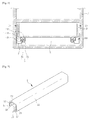
FIG. 1 is a cross-sectional view of a rail according to an embodiment of the present invention coupled to a drawer; -
FIG. 2 is a perspective view of a movable rail shown inFIG. 1 ; -
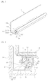
FIG. 3 is a perspective view of a fixed rail shown inFIG. 1 ; -
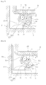
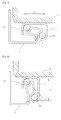
FIGS. 4 and5 are views for describing methods of installing a fixed rail provided in the rail according to the embodiment of the present invention; -
FIG. 6 is a cross-sectional view showing a torsional load applied to the rail according to the embodiment of the present invention; and -
FIGS. 7 and 8 are views for describing a shape of a frame according to an angle formed by a straight line passing through a center of a rolling body installed at the rail according to the embodiment of the present invention and a bottom surface of the drawer. - Hereinafter, an embodiment of the present invention will be described in detail with reference to the accompanying drawings.
- All terms used herein are equal to the general meaning of terms that can be understood by those skilled in the art unless the context clearly indicates otherwise, and if the terms used herein collide with the general meaning of the terms, the terms will be used as definition used herein.
- Meanwhile, a configuration or a control method of an apparatus, which will be described below, is provided not to limit the scope of the present invention but provided to describe an embodiment of the present invention. Like reference numerals designate like elements throughout the description.
- A
rail 100 according to an embodiment of the present invention is installed at an object F such as furniture, a home appliance, or the like, having a drawer accommodating section S in which a drawer D is accommodated. Therail 100 includes amovable rail 1 coupled to a lower surface of the drawer D, afixed rail 7 having one end fixed to a bottom surface or a side surface of the drawer accommodating section S and the other end disposed in themovable rail 1, and arolling body 3 disposed in themovable rail 1 and supported by thefixed rail 7 to enable movement of themovable rail 1. - As shown in
FIG. 2 , themovable rail 1 includes aframe 11 fixed to a lower surface of the drawer D and having at least one open end of both opposite ends (front and rear surfaces in the drawing). - An
accommodating space 13 in which therolling body 3 and a ball support section 73 (to be described below) of the fixedrail 7 are accommodated is installed in theframe 11, and theaccommodating space 13 is configured to be in communication with the outside of theframe 11 through anopen surface 15. - Meanwhile, the
movable rail 1 may further include slidingsurfaces 17 installed in a longitudinal direction thereof and disposed at an inner circumferential surface of theaccommodating space 13 to support therolling body 3, and thesliding surfaces 17 may be installed at both corners opposite to each other in a diagonal direction of theframe 11, respectively. - The
rolling body 3 includes a lowerrolling body 31 disposed at a lower portion of theaccommodating space 13 and an upper rollingbody 33 disposed at an upper portion in the diagonal direction of the lowerrolling body 31, and the plurality ofrolling bodies frame 11. - A straight line passing through the lower
rolling body 31 and the upperrolling body 33 may be inclined with respect to a lower surface of the drawer D by a predetermined angle (see reference character A ofFIG. 4 ). Accordingly, when a torsional load (see reference character f2 ofFIG. 6 ) is applied to therail 100 due to the weight of the drawer D and the weight of the accommodated matters, a resistance force of therail 100 is increased. - Meanwhile, when a line connecting centers of the
rolling bodies body 33 and the lowerrolling body 31 should be increased in a direction parallel to the bottom surface of the drawer D, a length of an upper surface of the frame 11 (see reference character L1 ofFIG. 7 ) may be increased to be vulnerable to the torsional load. - In addition, since the gap between the upper
rolling body 33 and the lowerrolling body 31 should be increased in a direction perpendicular to the bottom surface of the drawer D when the line connecting the centers of therolling bodies frame 11 may be interfered with the fixed rail 7 (to be described below) when a length (see reference character L2 ofFIG. 7 ) of the side surface of theframe 11 is increased and the vertical load, the torsional load, or the side surface external force is applied to theframe 11. - Accordingly, an angle A formed by the line connecting the centers of the lower
rolling body 31 and the upper rollingbody 33 and the bottom surface of the drawer D may be set within a range of 40 to 50 degrees, and thus therail 100 according to the embodiment can have an increased resistance against the vertical load and the torsional load due to the drawer D and the accommodated matters. - Meanwhile, while each of the
rolling bodies FIG. 2 is shown as therolling body 3 having a ball or a spherical shape, the rolling body installed at therail 100 according to the embodiment of the present invention may be modified in various shapes different from the shown shape as long as themovable rail 1 is movable by the rolling body. - When the
rolling bodies rolling bodies movable rail 1 and provided at both corners opposite to each other in a diagonal direction of themovable rail 1. Here, the number of balls provided in each of the ball arrays (not shown) may be varied according to an accommodating volume of the drawer D and a width of the drawer D. - In addition, when each of the
rolling bodies rail 100 according to the embodiment of the present invention may further include a ball retainer (seereference numeral 5 ofFIGS. 4 and5 ) disposed in theaccommodating space 13 and in which each of therolling bodies - The
ball retainer 5 is configured to maintain a gap between therolling bodies accommodating space 13 while rotatably supporting therolling bodies ball retainer 5 may include a retainer frame (not shown) disposed in theaccommodating space 13 and an accommodating groove (not shown) provided in the retainer frame (not shown) to accommodate therolling bodies ball retainer 5 may be modified in various types that can implement the above-mentioned functions. - As shown in
FIG. 3 , thefixed rail 7 includes afixing section 71 fixed to the drawer accommodating section S, theball support section 73 disposed in theaccommodating space 13 to support therolling body 3, and a connectingsection 75 having one end connected to theball support section 73 and the other end disposed at the outside of theframe 11 and connected to thefixing section 71 via theopen surface 15. - The
fixed rail 7 may be configured to include theball support section 73, the connectingsection 75, and thefixing section 71 by folding one plate member. - The fixing
section 71 may be configured to be fixed to the bottom surface of the drawer accommodating section S as shown inFIG. 5 , or may be configured to include aflange 711 configured to fix the fixedrail 7 to a sidewall of the drawer accommodating section S as shown inFIG. 4 . - The connecting
section 75 is configured to be inclined with respect to the fixingsection 71 by a predetermined angle B. Accordingly, even when the vertical load or torsional load (see reference character f2 ofFIG. 6 ) is applied to therail 100 by the weight of the drawer D and the weight of the accommodated matters, interference between themovable rail 1 and the fixedrail 7 can be prevented. The angle B between the connectingsection 75 and the fixingsection 71 may be set within a range from 50 to 70 degrees, in particular, 60 degrees. - When the connecting
section 75 has an angle larger than 70 degrees with respect to the fixingsection 71, since the vertical load and the torsional load are applied to theframe 11, the connectingsection 75 and theframe 11 may be interfered with each other to disturb the pulling-out or pushing-in of the drawer D. In addition, when the connectingsection 75 has an angle smaller than 50 degrees with respect to the fixingsection 71, theframe 11 may come in contact with the bottom surface of the drawer accommodating section S when the vertical load or the torsional load is applied. - In addition, when the connecting
section 75 is inclined to have an angle within a range from 50 to 70 degrees with respect to the fixingsection 71, a resistance against the side surface external force (or a side surface collision) applied to the side surface of the drawer D may be increased when the drawer D is pulled out. - That is, provided that the drawer D is pulled out of the drawer accommodating section S and a side surface external force f1 as shown in
FIG. 1 is applied to the side surface of the drawer D, when the connectingsection 75 has an angle smaller than 50 degrees with respect to the fixingsection 71, the side surface external force f1 cannot be easily supported, and when the angle is larger than 70 degrees, an interference between the connectingsection 75 and theframe 11 by the side surface external force f1 may occur. However, when the connectingsection 75 has the inclination angle B within a range from 50 to 70 degrees with respect to the fixingsection 71, the side surface external force f1 can be effectively supported to minimize the above-mentioned problems. - The
ball support section 73 may include a firstball seating surface 731 extending from the connectingsection 75 and configured to accommodate thelower rolling body 31, a secondball seating surface 733 connected to the firstball seating surface 731 through a bendingsurface 735 and configured to accommodate the upper rollingbody 33, and aseating surface supporter 737 extending from the secondball seating surface 733 and configured to come in contact with the connectingsection 75. - The second
ball seating surface 733 is configured to support the upper rollingbody 33 to support most of the vertical load of the drawer D and the accommodated matters, and the firstball seating surface 731 is configured to support thelower rolling body 31 to support the torsional load (see reference character f2 ofFIG. 6 ) applied to the secondball seating surface 733 and theframe 11. - Further, the first
ball seating surface 731 and the connectingsection 75 may be connected to each other while forming a boundary surface P. - That is, the first
ball seating surface 731 may be connected to the connectingsection 75 and bent in a direction in which the secondball seating surface 733 is formed such that thelower rolling body 31 is disposed at a position interfered with an imaginary line extending from the connectingsection 75. - When the load caused by the drawer D and the accommodated matters is applied to the
rail 100, an effect of preventing separation of thelower rolling body 31 between theframe 11 and theball support section 73 is provided. - Meanwhile, the
seating surface supporter 737 includes anextension section 7371 extending from the secondball seating surface 733 in a direction of the connectingsection 75 as a means configured to increase a resistance of therail 100 when the vertical load and the torsional load caused by the drawer D and the accommodated matters are applied to therail 100, and abending section 7373 formed by bending one end of theextension section 7371 and configured to come in contact with an upper portion of the connectingsection 75. - In this case, the
extension section 7371 may be inclined to have a predetermined angle C within a range from 35 to 55 degrees with respect to the bottom surface of the drawer D, and in particular, theextension section 7371 may have an angle of 45 degrees with respect to the bottom surface of the drawer D (an angle of 45 degrees with respect to the bottom surface of the drawer accommodating section S). - Provided that the
extension section 7371 is disposed parallel to the bottom surface of the drawer D (an angle of 35 degrees or less) or has an angle of 55 degrees or more, a force applied to thelower rolling body 31 and the upper rollingbody 33 cannot be effectively overcome when the vertical load and the torsional load are applied to therail 100. - Meanwhile, the
ball support section 73 may be formed by bending one plate member. In this case, theseating surface supporter 737 may be configured to come in contact with the connectingsection 75 to form a closed curve of a cross-sectional shape of theball support section 73 and configured to form a predetermined space such that the firstball seating surface 731 is spaced a predetermined distance apart from the secondball seating surface 733, and thebending section 7373 of theseating surface supporter 737 may be adhered to a position (the connecting section 75) near the firstball seating surface 731, the boundary surface P of the firstball seating surface 731, and so on. - This is because the load of the drawer D and the accommodated matters transmitted through the rolling
bodies ball support section 73. - That is, when the load (the vertical load and the side surface external force) of the drawer D and the accommodated matters is transmitted to the first
ball seating surface 731 and the secondball seating surface 733 through the rollingbodies ball seating surface 731 and the secondball seating surface 733 can be maintained as thebending section 7373 of theseating surface supporter 737 is adhered to the connectingsection 75 to support the load while theextension section 7371 of theseating surface supporter 737 is compressed, even when the fixedrail 7 has theball support section 73 formed by bending a thin plate member, the load transmitted from the rollingbodies - In order to maximize the above-mentioned effects, the
bending section 7373 of theseating surface supporter 737 may be adhered and fixed to the connectingsection 75 to increase adhesion to the connectingsection 75 through welding or the like. - However, adhesion and fixing of the
bending section 7373 and the connectingsection 75 may be performed by continuously or partially fixing thebending section 7373 to the connectingsection 75 in the longitudinal direction of the fixedrail 7. - That is, the
bending section 7373 and the connectingsection 75 may be configured such that thebending section 7373 and the connectingsection 75 are adhered to at least a portion of a contact section between thebending section 7373 and the connectingsection 75 formed in the longitudinal direction of the fixedrail 7, fixing thebending section 7373 to the connectingsection 75. - Hereinafter, functions and effects of the
rail 100 according to the embodiment of the present invention having the above-mentioned structure will be described with reference toFIG. 6 . - When a user pulls the drawer D out of the drawer accommodating section S in a state in which the drawer D is accommodated in the drawer accommodating section S, the
movable rail 1 fixed to the lower surface of the drawer D is moved through guidance of the fixedrail 7, and here, the rollingbodies movable rail 1 and the fixedrail 7 to assist movement of themovable rail 1. - Meanwhile, when the drawer D is pulled out of the drawer accommodating section S as well as when the drawer D is disposed in the drawer accommodating section S, the torsional load f2 is applied to the
rail 100 by the weight of the drawer D and the weight (the load) of the accommodated matters. - Here, since the rolling
bodies frame 11 of themovable rail 1 are installed at both corners opposite to each other in the diagonal direction of theframe 11, respectively, and the line connecting the centers of the rollingbodies lower rolling body 31 is disposed closer to the central direction of the drawer D than the upper rollingbody 33, thelower rolling body 31 can endure the torsional load. - In addition, since the
seating surface supporter 737 is installed at theball support section 73 of the fixedrail 7 and theextension section 7371 of theseating surface supporter 737 is supported by the connectingsection 75 through thebending section 7373, even when thelower rolling body 31 is pressed by theframe 11 due to the torsional load f2, thebending section 7373 supports the load while theextension section 7371 is compressed with adhesion to the connectingsection 75. Accordingly, the upper rollingbody 33 and thelower rolling body 31 can be securely supported, and deformation and loss of function of therail 100 due to the torsional load f2 can be prevented. - In addition, in case of the conventional rail (not shown), when the torsional load f2 or the side surface external force f1 is applied to the rail, while the movable rail is interfered with the fixed rail to make it difficult to pull or push the drawer, since the
rail 100 according to the embodiment of the present invention is configured such that the connectingsection 75 has the angle B of 50 to 70 degrees with respect to the bottom surface of the fixingsection 71 or the drawer accommodating section S, the above-mentioned problems can be solved. - That is, since the connecting
section 75 installed at therail 100 according to the embodiment of the present invention is inclined with respect to the fixingsection 71 by the predetermined angle B to pass through theopen surface 15, connect the fixingsection 71 and theball support section 73, and maintain a certain distance from theopen surface 15, even when theframe 11 is moved clockwise by the torsional load f2 or the drawer D is moved to one side by the side surface external force f1, an interference between theframe 11 and the connectingsection 75 can be prevented. - While the invention has been shown and described with reference to certain example embodiments thereof, it will be understood by those skilled in the art that various changes in form and details may be made therein without departing from the spirit and scope of the invention as defined by the appended claims.
- Since the rail according to the embodiment of the present invention has a simple structure and can stably support the load of the drawer to enable easy manufacture thereof, and an influence due to the torsional load can be minimized to improve durability of the drawer and reduce generation of noises, the rail can be usefully utilized in a drawer manufacturing field.
Claims (10)
- A rail installed at an object having a drawer accommodating section in which a drawer is accommodated and configured to pull or push the drawer out of or into the drawer accommodating section, the rail comprising:a movable rail having an accommodating space formed therein, configured to bring the accommodating space in communication with the outside through an open surface, and fixed to a lower surface of the drawer;a rolling body disposed in the accommodating space and installed at both corners opposite to each other in a diagonal direction of the movable rail; anda fixed rail including a fixing section fixed to the drawer accommodating section, a ball support section disposed in the accommodating space and configured to support the rolling body, and a connecting section having one end connected to the ball support section and the other end pulled out of the accommodating space through the open surface and connected to the fixing section,wherein the connecting section is configured to have an angle within a range from 50 to 70 degrees with respect to the fixing section to prevent interference between the open surface and the connecting section even when the movable rail is pressed by the drawer.
- The rail according to claim 1, wherein the rolling body is constituted by two rows of balls disposed in a longitudinal direction of the movable rail at both comers opposite to each other in a diagonal direction of the movable rail.
- The rail according to claim 1, wherein the rolling bodies installed at both corners opposite to each other in the diagonal direction of the movable rail are configured such that a line connecting centers of the rolling bodies has an angle within a range from 40 to 50 degrees with respect to a lower surface of the drawer.
- The rail according to claim 1, wherein the fixed rail is formed by bending one plate member such that the ball support section, the connecting section, and the fixing section are integrally formed.
- The rail according to claim 4, wherein the ball support section further comprises:a first ball seating surface extending from the connecting section and in which the rolling body, which is disposed at a lower side, of the rolling bodies installed at both corners opposite to each other in the diagonal direction of the movable rail is accommodated;a second ball seating surface in which the rolling body, which is disposed at an upper side, of the rolling bodies installed at both corners opposite to each other in the diagonal direction of the movable rail is accommodated;a bending surface configured to connect the first ball seating surface and the second ball seating surface; anda seating surface supporter having an extension section extending from the second ball seating surface and a bending section formed by bending the extension section and in contact with an upper portion of the connecting section,wherein the first ball seating surface, the bending surface, the second ball seating surface, and the seating surface supporter are configured such that a cross-sectional shape of the ball support section forms a closed curve, and the first ball seating surface and the second ball seating surface are spaced a predetermined distance apart from each other by the extension section.
- The rail according to claim 5, wherein the extension section has an angle within a range from 35 to 55 degrees with respect to the lower surface of the drawer.
- The rail according to claim 5, wherein the ball support section further comprises a boundary surface disposed between the connecting section and the first ball seating surface to be located at a position at which the lower rolling body is interfered with an imaginary line extending from the connecting section, and formed by bending the first ball seating surface in a direction of the second ball seating surface.
- The rail according to claim 7, wherein the bending section is in contact with the connecting section and disposed on the boundary surface.
- The rail according to claim 5, wherein the bending section and the connecting section are adhered to each other at a partial section of a contact section between the bending section and the connecting section formed in the longitudinal direction of the fixed rail to fix the bending section to the connecting section.
- The rail according to claim 1, wherein the movable rails are installed at both opposite ends of the lower surface of the drawer such that the open surfaces are directed toward corners between the side surfaces and the bottom surface of the drawer accommodating section,
the fixed rails are configured such that the fixing sections are fixed to both opposite ends of the drawer accommodating section, and
the rolling bodies installed at both corners opposite to each other in a diagonal direction of the movable rails are configured such that a line connecting centers of the rolling bodies has an angle within a range from 40 to 50 degrees with respect to the lower surface of the drawer.
Applications Claiming Priority (3)
| Application Number | Priority Date | Filing Date | Title |
|---|---|---|---|
| KR20110082132 | 2011-08-18 | ||
| KR1020110092165A KR101114486B1 (en) | 2011-08-18 | 2011-09-09 | Rail for drawer |
| PCT/KR2012/003054 WO2013024956A1 (en) | 2011-08-18 | 2012-04-20 | Rail |
Publications (3)
| Publication Number | Publication Date |
|---|---|
| EP2745738A1 true EP2745738A1 (en) | 2014-06-25 |
| EP2745738A4 EP2745738A4 (en) | 2015-04-01 |
| EP2745738B1 EP2745738B1 (en) | 2020-07-29 |
Family
ID=45840383
Family Applications (1)
| Application Number | Title | Priority Date | Filing Date |
|---|---|---|---|
| EP12823852.4A Active EP2745738B1 (en) | 2011-08-18 | 2012-04-20 | Rail |
Country Status (5)
| Country | Link |
|---|---|
| US (1) | US9427084B2 (en) |
| EP (1) | EP2745738B1 (en) |
| KR (1) | KR101114486B1 (en) |
| CN (1) | CN103747705B (en) |
| WO (1) | WO2013024956A1 (en) |
Cited By (3)
| Publication number | Priority date | Publication date | Assignee | Title |
|---|---|---|---|---|
| DE102015109220A1 (en) * | 2015-06-10 | 2016-12-15 | Paul Hettich Gmbh & Co. Kg | Pull-out guide for a flushing device and flushing device |
| CN106402309A (en) * | 2016-11-10 | 2017-02-15 | 无锡市明盛强力风机有限公司 | Solid-lubricated ball screw |
| CN106438899A (en) * | 2016-11-10 | 2017-02-22 | 无锡市明盛强力风机有限公司 | Solid lubricating type ball screw rod |
Families Citing this family (16)
| Publication number | Priority date | Publication date | Assignee | Title |
|---|---|---|---|---|
| CN105208895A (en) * | 2013-06-11 | 2015-12-30 | Segos株式会社 | Ball retainer, slide apparatus comprising same and mold for manufacturing same |
| EP3148376B1 (en) * | 2014-05-28 | 2018-05-02 | Inter IKEA Systems B.V. | Sequential household effects slid |
| AT515690B1 (en) * | 2014-06-23 | 2015-11-15 | Fulterer Gmbh | pull-out |
| DE202014103864U1 (en) * | 2014-08-20 | 2015-11-23 | Grass America, Inc. | Pull-out guide for guiding a drawer and furniture with a pull-out guide |
| KR101650124B1 (en) * | 2014-11-07 | 2016-08-23 | 차현호 | Slide device for composite load properly |
| PL3284369T3 (en) * | 2015-04-13 | 2020-06-15 | Segos Co., Ltd. | Slide unit for drawer |
| WO2016167576A1 (en) * | 2015-04-13 | 2016-10-20 | (주)세고스 | Slide unit for drawer |
| DE102015110560A1 (en) * | 2015-07-01 | 2017-01-05 | Form Orange Produktentwicklung | Drawer with a base plate, two side walls, a rear wall and a panel |
| CN106388349A (en) * | 2016-11-10 | 2017-02-15 | 无锡市明盛强力风机有限公司 | Self-lubricating sliding rail |
| CN106473480A (en) * | 2016-11-10 | 2017-03-08 | 无锡市明盛强力风机有限公司 | A kind of self-lubricating slide rail |
| CN106333528A (en) * | 2016-11-10 | 2017-01-18 | 无锡市明盛强力风机有限公司 | Self-lubricating Slide Rail |
| CN106419209A (en) * | 2016-11-10 | 2017-02-22 | 无锡市明盛强力风机有限公司 | Self-lubricating sliding rail |
| CN106308153A (en) * | 2016-11-10 | 2017-01-11 | 无锡市明盛强力风机有限公司 | Self-lubrication sliding rail |
| KR102089292B1 (en) * | 2017-11-28 | 2020-03-16 | (주)세고스 | Slide unit |
| JP6599042B1 (en) * | 2019-08-05 | 2019-10-30 | カルソニックカンセイ株式会社 | Pull-out storage box |
| CN114009968A (en) * | 2021-11-10 | 2022-02-08 | 佛山市顺德区美的洗涤电器制造有限公司 | Storage cabinet and integrated stove |
Citations (3)
| Publication number | Priority date | Publication date | Assignee | Title |
|---|---|---|---|---|
| DE3127701A1 (en) * | 1981-07-14 | 1983-02-10 | Karl Lautenschläger KG, Möbelbeschlagfabrik, 6107 Reinheim | Roller extension guide |
| EP0158811A2 (en) * | 1984-04-17 | 1985-10-23 | Häfele KG | Guide, in particular for extensible parts of furniture |
| DE29807536U1 (en) * | 1998-04-29 | 1998-06-10 | Hettich Paul Gmbh & Co | Drawer extension |
Family Cites Families (17)
| Publication number | Priority date | Publication date | Assignee | Title |
|---|---|---|---|---|
| GB8529940D0 (en) * | 1985-12-04 | 1986-01-15 | Jackson P A S | Ball slide system |
| DE9307088U1 (en) * | 1993-05-12 | 1993-07-01 | Hettich Paul Gmbh & Co | |
| AT407473B (en) * | 1994-07-07 | 2001-03-26 | Alfit Ag | FULL EXTENSION FOR DRAWERS |
| DE29507916U1 (en) * | 1995-05-17 | 1995-08-10 | Hettich Paul Gmbh & Co | Drawer drawer slide |
| CN2265720Y (en) * | 1996-08-23 | 1997-10-29 | 宁波保税区华琳实业有限公司 | Multisection telescopic guide rail for cupboard |
| DE29807540U1 (en) * | 1998-04-29 | 1998-06-10 | Hettich Paul Gmbh & Co | Drawer extension |
| DE19931842B4 (en) * | 1999-07-09 | 2011-03-10 | Paul Hettich Gmbh & Co. Kg | Pull-out guide with cylindrical triangularly arranged rolling elements |
| DE10206075A1 (en) * | 2002-02-13 | 2003-11-13 | Westfalia Profiltechnik Gmbh & | Adjustment or rail system of vehicle seats, drawers, pull-outs for workshop trolleys or the like |
| AT412181B (en) * | 2002-04-02 | 2004-11-25 | Fulterer Gmbh | UNDERFLOOR EXTENSION GUIDE FOR EXTENDABLE FURNITURE PARTS |
| PL1475014T3 (en) * | 2003-05-05 | 2006-12-29 | Blum Gmbh Julius | Drawer slide fitting |
| DE112006000842B4 (en) * | 2005-04-28 | 2018-09-27 | Thk Co., Ltd. | Slide rail unit with holding function |
| US20060273705A1 (en) * | 2005-06-07 | 2006-12-07 | Kuo-Liang Yeh | Drawer slide assembly |
| DK200700224A (en) * | 2007-02-12 | 2008-08-13 | Inter Ikea Sys Bv | Extension device for a drawer |
| KR101024082B1 (en) * | 2008-12-31 | 2011-03-22 | (주)세고스 | sliding apparatus |
| WO2010077027A2 (en) * | 2008-12-31 | 2010-07-08 | (주)세고스 | Sliding device |
| KR101021574B1 (en) * | 2008-12-31 | 2011-03-17 | (주)세고스 | sliding apparatus |
| DE102009003741A1 (en) * | 2009-04-03 | 2010-10-07 | Paul Hettich Gmbh & Co. Kg | Pull-out guide and oven and process for their coating |
-
2011
- 2011-09-09 KR KR1020110092165A patent/KR101114486B1/en active IP Right Grant
-
2012
- 2012-04-20 EP EP12823852.4A patent/EP2745738B1/en active Active
- 2012-04-20 US US14/110,740 patent/US9427084B2/en active Active
- 2012-04-20 CN CN201280012401.8A patent/CN103747705B/en active Active
- 2012-04-20 WO PCT/KR2012/003054 patent/WO2013024956A1/en active Application Filing
Patent Citations (3)
| Publication number | Priority date | Publication date | Assignee | Title |
|---|---|---|---|---|
| DE3127701A1 (en) * | 1981-07-14 | 1983-02-10 | Karl Lautenschläger KG, Möbelbeschlagfabrik, 6107 Reinheim | Roller extension guide |
| EP0158811A2 (en) * | 1984-04-17 | 1985-10-23 | Häfele KG | Guide, in particular for extensible parts of furniture |
| DE29807536U1 (en) * | 1998-04-29 | 1998-06-10 | Hettich Paul Gmbh & Co | Drawer extension |
Non-Patent Citations (1)
| Title |
|---|
| See also references of WO2013024956A1 * |
Cited By (3)
| Publication number | Priority date | Publication date | Assignee | Title |
|---|---|---|---|---|
| DE102015109220A1 (en) * | 2015-06-10 | 2016-12-15 | Paul Hettich Gmbh & Co. Kg | Pull-out guide for a flushing device and flushing device |
| CN106402309A (en) * | 2016-11-10 | 2017-02-15 | 无锡市明盛强力风机有限公司 | Solid-lubricated ball screw |
| CN106438899A (en) * | 2016-11-10 | 2017-02-22 | 无锡市明盛强力风机有限公司 | Solid lubricating type ball screw rod |
Also Published As
| Publication number | Publication date |
|---|---|
| EP2745738B1 (en) | 2020-07-29 |
| CN103747705A (en) | 2014-04-23 |
| WO2013024956A1 (en) | 2013-02-21 |
| KR101114486B1 (en) | 2012-02-24 |
| EP2745738A4 (en) | 2015-04-01 |
| US20140167588A1 (en) | 2014-06-19 |
| CN103747705B (en) | 2015-09-02 |
| US9427084B2 (en) | 2016-08-30 |
Similar Documents
| Publication | Publication Date | Title |
|---|---|---|
| EP2745738B1 (en) | Rail | |
| US20150250311A1 (en) | Drawer guide and method for mounting a drawer to a carcass | |
| US20070080616A1 (en) | Sliding guide rail system for a drawer | |
| US9211008B2 (en) | Slide assembly | |
| WO2012015294A1 (en) | Drawer guide rail system | |
| US8485616B2 (en) | Slide assembly with buffering member for reducing impact and noise | |
| CN112392343A (en) | Door checker and method of holding a door in a desired open position | |
| EP2308348A2 (en) | Bottom-mounted slide and manufacturing method thereof | |
| KR20070085765A (en) | Undermount drawer slide | |
| US20150211574A1 (en) | Slide assembly | |
| US20220304472A1 (en) | Connecting fitting, item of furniture, device for connecting furniture parts, and method for assembling a piece of furniture | |
| TW201302128A (en) | A pull-out guide assembly for a drawer | |
| JPWO2008038472A1 (en) | Slide rail unit | |
| EP2532274B1 (en) | Apparatus for fixing slide rail | |
| US8646856B2 (en) | Bottom-mounted slide and manufacturing method thereof | |
| US20150159415A1 (en) | Pull-out guide | |
| KR20160065725A (en) | Fixing apparatus for sliding rail | |
| CN105078031A (en) | Integrated optimized structure of drawer of furniture | |
| CN103025202B (en) | Drawer having two side panels and a rear wall | |
| US20150282374A1 (en) | Slide rail assembly | |
| CN108633301B (en) | Slide rail fixing device | |
| US9941677B2 (en) | Electrical wire guide | |
| US10842267B2 (en) | Movement mechanism for a guidance system | |
| KR101650124B1 (en) | Slide device for composite load properly | |
| US20190166997A1 (en) | Carriage for a guide system, and method for producing a carriage |
Legal Events
| Date | Code | Title | Description |
|---|---|---|---|
| PUAI | Public reference made under article 153(3) epc to a published international application that has entered the european phase |
Free format text: ORIGINAL CODE: 0009012 |
|
| 17P | Request for examination filed |
Effective date: 20131209 |
|
| AK | Designated contracting states |
Kind code of ref document: A1 Designated state(s): AL AT BE BG CH CY CZ DE DK EE ES FI FR GB GR HR HU IE IS IT LI LT LU LV MC MK MT NL NO PL PT RO RS SE SI SK SM TR |
|
| DAX | Request for extension of the european patent (deleted) | ||
| A4 | Supplementary search report drawn up and despatched |
Effective date: 20150302 |
|
| RIC1 | Information provided on ipc code assigned before grant |
Ipc: A47B 88/00 20060101ALI20150224BHEP Ipc: A47B 88/14 20060101ALI20150224BHEP Ipc: A47B 88/12 20060101AFI20150224BHEP Ipc: A47B 88/10 20060101ALI20150224BHEP |
|
| REG | Reference to a national code |
Ref country code: DE Ref legal event code: R079 Ref document number: 602012071518 Country of ref document: DE Free format text: PREVIOUS MAIN CLASS: A47B0088120000 Ipc: A47B0088487000 |
|
| GRAP | Despatch of communication of intention to grant a patent |
Free format text: ORIGINAL CODE: EPIDOSNIGR1 |
|
| STAA | Information on the status of an ep patent application or granted ep patent |
Free format text: STATUS: GRANT OF PATENT IS INTENDED |
|
| RIC1 | Information provided on ipc code assigned before grant |
Ipc: A47B 88/487 20170101AFI20200131BHEP Ipc: A47B 88/497 20170101ALI20200131BHEP |
|
| INTG | Intention to grant announced |
Effective date: 20200218 |
|
| GRAS | Grant fee paid |
Free format text: ORIGINAL CODE: EPIDOSNIGR3 |
|
| GRAA | (expected) grant |
Free format text: ORIGINAL CODE: 0009210 |
|
| STAA | Information on the status of an ep patent application or granted ep patent |
Free format text: STATUS: THE PATENT HAS BEEN GRANTED |
|
| AK | Designated contracting states |
Kind code of ref document: B1 Designated state(s): AL AT BE BG CH CY CZ DE DK EE ES FI FR GB GR HR HU IE IS IT LI LT LU LV MC MK MT NL NO PL PT RO RS SE SI SK SM TR |
|
| REG | Reference to a national code |
Ref country code: GB Ref legal event code: FG4D |
|
| RIN1 | Information on inventor provided before grant (corrected) |
Inventor name: LEE, DONG HEE Inventor name: PARK, YOON SIK Inventor name: CHA, HYUN HO |
|
| REG | Reference to a national code |
Ref country code: CH Ref legal event code: EP |
|
| REG | Reference to a national code |
Ref country code: DE Ref legal event code: R096 Ref document number: 602012071518 Country of ref document: DE |
|
| REG | Reference to a national code |
Ref country code: AT Ref legal event code: REF Ref document number: 1294789 Country of ref document: AT Kind code of ref document: T Effective date: 20200815 |
|
| REG | Reference to a national code |
Ref country code: IE Ref legal event code: FG4D |
|
| REG | Reference to a national code |
Ref country code: LT Ref legal event code: MG4D |
|
| REG | Reference to a national code |
Ref country code: NL Ref legal event code: MP Effective date: 20200729 |
|
| REG | Reference to a national code |
Ref country code: AT Ref legal event code: MK05 Ref document number: 1294789 Country of ref document: AT Kind code of ref document: T Effective date: 20200729 |
|
| PG25 | Lapsed in a contracting state [announced via postgrant information from national office to epo] |
Ref country code: FI Free format text: LAPSE BECAUSE OF FAILURE TO SUBMIT A TRANSLATION OF THE DESCRIPTION OR TO PAY THE FEE WITHIN THE PRESCRIBED TIME-LIMIT Effective date: 20200729 Ref country code: GR Free format text: LAPSE BECAUSE OF FAILURE TO SUBMIT A TRANSLATION OF THE DESCRIPTION OR TO PAY THE FEE WITHIN THE PRESCRIBED TIME-LIMIT Effective date: 20201030 Ref country code: LT Free format text: LAPSE BECAUSE OF FAILURE TO SUBMIT A TRANSLATION OF THE DESCRIPTION OR TO PAY THE FEE WITHIN THE PRESCRIBED TIME-LIMIT Effective date: 20200729 Ref country code: BG Free format text: LAPSE BECAUSE OF FAILURE TO SUBMIT A TRANSLATION OF THE DESCRIPTION OR TO PAY THE FEE WITHIN THE PRESCRIBED TIME-LIMIT Effective date: 20201029 Ref country code: ES Free format text: LAPSE BECAUSE OF FAILURE TO SUBMIT A TRANSLATION OF THE DESCRIPTION OR TO PAY THE FEE WITHIN THE PRESCRIBED TIME-LIMIT Effective date: 20200729 Ref country code: AT Free format text: LAPSE BECAUSE OF FAILURE TO SUBMIT A TRANSLATION OF THE DESCRIPTION OR TO PAY THE FEE WITHIN THE PRESCRIBED TIME-LIMIT Effective date: 20200729 Ref country code: NO Free format text: LAPSE BECAUSE OF FAILURE TO SUBMIT A TRANSLATION OF THE DESCRIPTION OR TO PAY THE FEE WITHIN THE PRESCRIBED TIME-LIMIT Effective date: 20201029 Ref country code: HR Free format text: LAPSE BECAUSE OF FAILURE TO SUBMIT A TRANSLATION OF THE DESCRIPTION OR TO PAY THE FEE WITHIN THE PRESCRIBED TIME-LIMIT Effective date: 20200729 Ref country code: SE Free format text: LAPSE BECAUSE OF FAILURE TO SUBMIT A TRANSLATION OF THE DESCRIPTION OR TO PAY THE FEE WITHIN THE PRESCRIBED TIME-LIMIT Effective date: 20200729 Ref country code: PT Free format text: LAPSE BECAUSE OF FAILURE TO SUBMIT A TRANSLATION OF THE DESCRIPTION OR TO PAY THE FEE WITHIN THE PRESCRIBED TIME-LIMIT Effective date: 20201130 |
|
| PG25 | Lapsed in a contracting state [announced via postgrant information from national office to epo] |
Ref country code: RS Free format text: LAPSE BECAUSE OF FAILURE TO SUBMIT A TRANSLATION OF THE DESCRIPTION OR TO PAY THE FEE WITHIN THE PRESCRIBED TIME-LIMIT Effective date: 20200729 Ref country code: LV Free format text: LAPSE BECAUSE OF FAILURE TO SUBMIT A TRANSLATION OF THE DESCRIPTION OR TO PAY THE FEE WITHIN THE PRESCRIBED TIME-LIMIT Effective date: 20200729 Ref country code: PL Free format text: LAPSE BECAUSE OF FAILURE TO SUBMIT A TRANSLATION OF THE DESCRIPTION OR TO PAY THE FEE WITHIN THE PRESCRIBED TIME-LIMIT Effective date: 20200729 Ref country code: IS Free format text: LAPSE BECAUSE OF FAILURE TO SUBMIT A TRANSLATION OF THE DESCRIPTION OR TO PAY THE FEE WITHIN THE PRESCRIBED TIME-LIMIT Effective date: 20201129 |
|
| PG25 | Lapsed in a contracting state [announced via postgrant information from national office to epo] |
Ref country code: NL Free format text: LAPSE BECAUSE OF FAILURE TO SUBMIT A TRANSLATION OF THE DESCRIPTION OR TO PAY THE FEE WITHIN THE PRESCRIBED TIME-LIMIT Effective date: 20200729 |
|
| PG25 | Lapsed in a contracting state [announced via postgrant information from national office to epo] |
Ref country code: RO Free format text: LAPSE BECAUSE OF FAILURE TO SUBMIT A TRANSLATION OF THE DESCRIPTION OR TO PAY THE FEE WITHIN THE PRESCRIBED TIME-LIMIT Effective date: 20200729 Ref country code: SM Free format text: LAPSE BECAUSE OF FAILURE TO SUBMIT A TRANSLATION OF THE DESCRIPTION OR TO PAY THE FEE WITHIN THE PRESCRIBED TIME-LIMIT Effective date: 20200729 Ref country code: CZ Free format text: LAPSE BECAUSE OF FAILURE TO SUBMIT A TRANSLATION OF THE DESCRIPTION OR TO PAY THE FEE WITHIN THE PRESCRIBED TIME-LIMIT Effective date: 20200729 Ref country code: EE Free format text: LAPSE BECAUSE OF FAILURE TO SUBMIT A TRANSLATION OF THE DESCRIPTION OR TO PAY THE FEE WITHIN THE PRESCRIBED TIME-LIMIT Effective date: 20200729 Ref country code: DK Free format text: LAPSE BECAUSE OF FAILURE TO SUBMIT A TRANSLATION OF THE DESCRIPTION OR TO PAY THE FEE WITHIN THE PRESCRIBED TIME-LIMIT Effective date: 20200729 Ref country code: IT Free format text: LAPSE BECAUSE OF FAILURE TO SUBMIT A TRANSLATION OF THE DESCRIPTION OR TO PAY THE FEE WITHIN THE PRESCRIBED TIME-LIMIT Effective date: 20200729 |
|
| REG | Reference to a national code |
Ref country code: DE Ref legal event code: R097 Ref document number: 602012071518 Country of ref document: DE |
|
| PG25 | Lapsed in a contracting state [announced via postgrant information from national office to epo] |
Ref country code: AL Free format text: LAPSE BECAUSE OF FAILURE TO SUBMIT A TRANSLATION OF THE DESCRIPTION OR TO PAY THE FEE WITHIN THE PRESCRIBED TIME-LIMIT Effective date: 20200729 |
|
| PLBE | No opposition filed within time limit |
Free format text: ORIGINAL CODE: 0009261 |
|
| STAA | Information on the status of an ep patent application or granted ep patent |
Free format text: STATUS: NO OPPOSITION FILED WITHIN TIME LIMIT |
|
| PG25 | Lapsed in a contracting state [announced via postgrant information from national office to epo] |
Ref country code: SK Free format text: LAPSE BECAUSE OF FAILURE TO SUBMIT A TRANSLATION OF THE DESCRIPTION OR TO PAY THE FEE WITHIN THE PRESCRIBED TIME-LIMIT Effective date: 20200729 |
|
| 26N | No opposition filed |
Effective date: 20210430 |
|
| PG25 | Lapsed in a contracting state [announced via postgrant information from national office to epo] |
Ref country code: SI Free format text: LAPSE BECAUSE OF FAILURE TO SUBMIT A TRANSLATION OF THE DESCRIPTION OR TO PAY THE FEE WITHIN THE PRESCRIBED TIME-LIMIT Effective date: 20200729 |
|
| PG25 | Lapsed in a contracting state [announced via postgrant information from national office to epo] |
Ref country code: MC Free format text: LAPSE BECAUSE OF FAILURE TO SUBMIT A TRANSLATION OF THE DESCRIPTION OR TO PAY THE FEE WITHIN THE PRESCRIBED TIME-LIMIT Effective date: 20200729 |
|
| PG25 | Lapsed in a contracting state [announced via postgrant information from national office to epo] |
Ref country code: LU Free format text: LAPSE BECAUSE OF NON-PAYMENT OF DUE FEES Effective date: 20210420 |
|
| REG | Reference to a national code |
Ref country code: BE Ref legal event code: MM Effective date: 20210430 |
|
| PG25 | Lapsed in a contracting state [announced via postgrant information from national office to epo] |
Ref country code: FR Free format text: LAPSE BECAUSE OF NON-PAYMENT OF DUE FEES Effective date: 20210430 Ref country code: LI Free format text: LAPSE BECAUSE OF NON-PAYMENT OF DUE FEES Effective date: 20210430 Ref country code: CH Free format text: LAPSE BECAUSE OF NON-PAYMENT OF DUE FEES Effective date: 20210430 |
|
| PG25 | Lapsed in a contracting state [announced via postgrant information from national office to epo] |
Ref country code: IE Free format text: LAPSE BECAUSE OF NON-PAYMENT OF DUE FEES Effective date: 20210420 |
|
| PG25 | Lapsed in a contracting state [announced via postgrant information from national office to epo] |
Ref country code: IS Free format text: LAPSE BECAUSE OF FAILURE TO SUBMIT A TRANSLATION OF THE DESCRIPTION OR TO PAY THE FEE WITHIN THE PRESCRIBED TIME-LIMIT Effective date: 20201129 |
|
| PG25 | Lapsed in a contracting state [announced via postgrant information from national office to epo] |
Ref country code: BE Free format text: LAPSE BECAUSE OF NON-PAYMENT OF DUE FEES Effective date: 20210430 |
|
| PG25 | Lapsed in a contracting state [announced via postgrant information from national office to epo] |
Ref country code: HU Free format text: LAPSE BECAUSE OF FAILURE TO SUBMIT A TRANSLATION OF THE DESCRIPTION OR TO PAY THE FEE WITHIN THE PRESCRIBED TIME-LIMIT; INVALID AB INITIO Effective date: 20120420 Ref country code: CY Free format text: LAPSE BECAUSE OF FAILURE TO SUBMIT A TRANSLATION OF THE DESCRIPTION OR TO PAY THE FEE WITHIN THE PRESCRIBED TIME-LIMIT Effective date: 20200729 |
|
| PGFP | Annual fee paid to national office [announced via postgrant information from national office to epo] |
Ref country code: TR Payment date: 20230324 Year of fee payment: 12 |
|
| PGFP | Annual fee paid to national office [announced via postgrant information from national office to epo] |
Ref country code: DE Payment date: 20230419 Year of fee payment: 12 |
|
| PGFP | Annual fee paid to national office [announced via postgrant information from national office to epo] |
Ref country code: GB Payment date: 20230417 Year of fee payment: 12 |