EP2745371B1 - Solar synchronized loads for photovoltaic systems - Google Patents
Solar synchronized loads for photovoltaic systems Download PDFInfo
- Publication number
- EP2745371B1 EP2745371B1 EP12762440.1A EP12762440A EP2745371B1 EP 2745371 B1 EP2745371 B1 EP 2745371B1 EP 12762440 A EP12762440 A EP 12762440A EP 2745371 B1 EP2745371 B1 EP 2745371B1
- Authority
- EP
- European Patent Office
- Prior art keywords
- load
- electrical
- power
- adjustable
- loads
- Prior art date
- Legal status (The legal status is an assumption and is not a legal conclusion. Google has not performed a legal analysis and makes no representation as to the accuracy of the status listed.)
- Revoked
Links
Images




Classifications
-
- H—ELECTRICITY
- H02—GENERATION; CONVERSION OR DISTRIBUTION OF ELECTRIC POWER
- H02J—ELECTRIC POWER NETWORKS; CIRCUIT ARRANGEMENTS OR SYSTEMS FOR SUPPLYING OR DISTRIBUTING ELECTRIC POWER; SYSTEMS FOR STORING ELECTRIC ENERGY
- H02J7/00—Circuit arrangements for charging or discharging batteries or for supplying loads from batteries
- H02J7/34—Parallel operation in networks using both storage and other DC sources, e.g. providing buffering
- H02J7/35—Parallel operation in networks using both storage and other DC sources, e.g. providing buffering with light sensitive cells
-
- H—ELECTRICITY
- H02—GENERATION; CONVERSION OR DISTRIBUTION OF ELECTRIC POWER
- H02J—ELECTRIC POWER NETWORKS; CIRCUIT ARRANGEMENTS OR SYSTEMS FOR SUPPLYING OR DISTRIBUTING ELECTRIC POWER; SYSTEMS FOR STORING ELECTRIC ENERGY
- H02J3/00—Circuit arrangements for AC mains or AC distribution networks
- H02J3/12—Arrangements for adjusting voltage in AC networks by changing a characteristic of the network load
- H02J3/14—Arrangements for adjusting voltage in AC networks by changing a characteristic of the network load by switching loads on to, or off from, the networks, e.g. progressively balanced loading
-
- H—ELECTRICITY
- H02—GENERATION; CONVERSION OR DISTRIBUTION OF ELECTRIC POWER
- H02J—ELECTRIC POWER NETWORKS; CIRCUIT ARRANGEMENTS OR SYSTEMS FOR SUPPLYING OR DISTRIBUTING ELECTRIC POWER; SYSTEMS FOR STORING ELECTRIC ENERGY
- H02J3/00—Circuit arrangements for AC mains or AC distribution networks
- H02J3/38—Arrangements for feeding a single network from two or more generators or sources in parallel; Arrangements for feeding already energised networks from additional generators or sources in parallel
- H02J3/381—Dispersed generators
-
- H—ELECTRICITY
- H02—GENERATION; CONVERSION OR DISTRIBUTION OF ELECTRIC POWER
- H02M—APPARATUS FOR CONVERSION BETWEEN AC AND AC, BETWEEN AC AND DC, OR BETWEEN DC AND DC, AND FOR USE WITH MAINS OR SIMILAR POWER SUPPLY SYSTEMS; CONVERSION OF DC OR AC INPUT POWER INTO SURGE OUTPUT POWER; CONTROL OR REGULATION THEREOF
- H02M7/00—Conversion of AC power input into DC power output; Conversion of DC power input into AC power output
- H02M7/42—Conversion of DC power input into AC power output without possibility of reversal
- H02M7/44—Conversion of DC power input into AC power output without possibility of reversal by static converters
-
- H—ELECTRICITY
- H02—GENERATION; CONVERSION OR DISTRIBUTION OF ELECTRIC POWER
- H02J—ELECTRIC POWER NETWORKS; CIRCUIT ARRANGEMENTS OR SYSTEMS FOR SUPPLYING OR DISTRIBUTING ELECTRIC POWER; SYSTEMS FOR STORING ELECTRIC ENERGY
- H02J2101/00—Supply or distribution of decentralised, dispersed or local electric power generation
- H02J2101/20—Dispersed power generation using renewable energy sources
- H02J2101/22—Solar energy
- H02J2101/24—Photovoltaics
-
- H—ELECTRICITY
- H02—GENERATION; CONVERSION OR DISTRIBUTION OF ELECTRIC POWER
- H02J—ELECTRIC POWER NETWORKS; CIRCUIT ARRANGEMENTS OR SYSTEMS FOR SUPPLYING OR DISTRIBUTING ELECTRIC POWER; SYSTEMS FOR STORING ELECTRIC ENERGY
- H02J2105/00—Networks for supplying or distributing electric power characterised by their spatial reach or by the load
- H02J2105/40—Networks for supplying or distributing electric power characterised by their spatial reach or by the load characterised by the loads connecting to the networks or being supplied by the networks
- H02J2105/42—Home appliances
-
- Y—GENERAL TAGGING OF NEW TECHNOLOGICAL DEVELOPMENTS; GENERAL TAGGING OF CROSS-SECTIONAL TECHNOLOGIES SPANNING OVER SEVERAL SECTIONS OF THE IPC; TECHNICAL SUBJECTS COVERED BY FORMER USPC CROSS-REFERENCE ART COLLECTIONS [XRACs] AND DIGESTS
- Y02—TECHNOLOGIES OR APPLICATIONS FOR MITIGATION OR ADAPTATION AGAINST CLIMATE CHANGE
- Y02B—CLIMATE CHANGE MITIGATION TECHNOLOGIES RELATED TO BUILDINGS, e.g. HOUSING, HOUSE APPLIANCES OR RELATED END-USER APPLICATIONS
- Y02B10/00—Integration of renewable energy sources in buildings
- Y02B10/10—Photovoltaic [PV]
-
- Y—GENERAL TAGGING OF NEW TECHNOLOGICAL DEVELOPMENTS; GENERAL TAGGING OF CROSS-SECTIONAL TECHNOLOGIES SPANNING OVER SEVERAL SECTIONS OF THE IPC; TECHNICAL SUBJECTS COVERED BY FORMER USPC CROSS-REFERENCE ART COLLECTIONS [XRACs] AND DIGESTS
- Y02—TECHNOLOGIES OR APPLICATIONS FOR MITIGATION OR ADAPTATION AGAINST CLIMATE CHANGE
- Y02B—CLIMATE CHANGE MITIGATION TECHNOLOGIES RELATED TO BUILDINGS, e.g. HOUSING, HOUSE APPLIANCES OR RELATED END-USER APPLICATIONS
- Y02B70/00—Technologies for an efficient end-user side electric power management and consumption
- Y02B70/30—Systems integrating technologies related to power network operation and communication or information technologies for improving the carbon footprint of the management of residential or tertiary loads, i.e. smart grids as climate change mitigation technology in the buildings sector, including also the last stages of power distribution and the control, monitoring or operating management systems at local level
- Y02B70/3225—Demand response systems, e.g. load shedding, peak shaving
-
- Y—GENERAL TAGGING OF NEW TECHNOLOGICAL DEVELOPMENTS; GENERAL TAGGING OF CROSS-SECTIONAL TECHNOLOGIES SPANNING OVER SEVERAL SECTIONS OF THE IPC; TECHNICAL SUBJECTS COVERED BY FORMER USPC CROSS-REFERENCE ART COLLECTIONS [XRACs] AND DIGESTS
- Y02—TECHNOLOGIES OR APPLICATIONS FOR MITIGATION OR ADAPTATION AGAINST CLIMATE CHANGE
- Y02E—REDUCTION OF GREENHOUSE GAS [GHG] EMISSIONS, RELATED TO ENERGY GENERATION, TRANSMISSION OR DISTRIBUTION
- Y02E10/00—Energy generation through renewable energy sources
- Y02E10/50—Photovoltaic [PV] energy
- Y02E10/56—Power conversion systems, e.g. maximum power point trackers
-
- Y—GENERAL TAGGING OF NEW TECHNOLOGICAL DEVELOPMENTS; GENERAL TAGGING OF CROSS-SECTIONAL TECHNOLOGIES SPANNING OVER SEVERAL SECTIONS OF THE IPC; TECHNICAL SUBJECTS COVERED BY FORMER USPC CROSS-REFERENCE ART COLLECTIONS [XRACs] AND DIGESTS
- Y04—INFORMATION OR COMMUNICATION TECHNOLOGIES HAVING AN IMPACT ON OTHER TECHNOLOGY AREAS
- Y04S—SYSTEMS INTEGRATING TECHNOLOGIES RELATED TO POWER NETWORK OPERATION, COMMUNICATION OR INFORMATION TECHNOLOGIES FOR IMPROVING THE ELECTRICAL POWER GENERATION, TRANSMISSION, DISTRIBUTION, MANAGEMENT OR USAGE, i.e. SMART GRIDS
- Y04S20/00—Management or operation of end-user stationary applications or the last stages of power distribution; Controlling, monitoring or operating thereof
- Y04S20/20—End-user application control systems
- Y04S20/222—Demand response systems, e.g. load shedding, peak shaving
-
- Y—GENERAL TAGGING OF NEW TECHNOLOGICAL DEVELOPMENTS; GENERAL TAGGING OF CROSS-SECTIONAL TECHNOLOGIES SPANNING OVER SEVERAL SECTIONS OF THE IPC; TECHNICAL SUBJECTS COVERED BY FORMER USPC CROSS-REFERENCE ART COLLECTIONS [XRACs] AND DIGESTS
- Y04—INFORMATION OR COMMUNICATION TECHNOLOGIES HAVING AN IMPACT ON OTHER TECHNOLOGY AREAS
- Y04S—SYSTEMS INTEGRATING TECHNOLOGIES RELATED TO POWER NETWORK OPERATION, COMMUNICATION OR INFORMATION TECHNOLOGIES FOR IMPROVING THE ELECTRICAL POWER GENERATION, TRANSMISSION, DISTRIBUTION, MANAGEMENT OR USAGE, i.e. SMART GRIDS
- Y04S20/00—Management or operation of end-user stationary applications or the last stages of power distribution; Controlling, monitoring or operating thereof
- Y04S20/20—End-user application control systems
- Y04S20/242—Home appliances
Definitions
- the present invention relates to solar power, and, more particularly, to running DC loads by use of solar power.
- PV solar photovoltaic
- DC direct current
- AC alternating current
- US20030182023A1 discloses a load controller and a method for maximizing effective capacity of PV supply system coupled to a variable AC load (e.g. HVAC).
- a variable AC load e.g. HVAC
- US2010274408 A1 discloses a system for balancing energy being consumed by a first device (AC powered HVAC) against the available energy being produced by a second separate device (photovoltaic energy source).
- US2009152947 A1 discloses a power management system for managing the power from solar panels and rechargeable batteries to power a system that includes DC loads and AC loads.
- WO2007018830 A2 and US2008258470 A1 disclose further related systems.
- the variable-speed DC motor may be controlled or adjusted to consume a maximum amount of the electrical output of the solar panels, increasing consumption when output is higher, lowering consumption when output is lower.
- An inverter that is either within (motor control circuits for instance) or separate from the HVAC equipment may operate in a bidirectional mode to invert the DC output from the solar array to AC for the home circuit if the output energy is not being entirely consumed by the variable-speed DC motor. This technique also enables the integration of a DC power bus within the home or commercial building for direct coupling to DC appliances and other DC devices.
- the invention comprises an electrical power supply arrangement including a solar power device that converts sunlight into DC electrical power.
- An adjustable DC load runs on the DC current electrical power.
- An electrical output sensing device senses a level of electrical output of the solar power device.
- a controller is coupled to each of the adjustable DC loads and the electrical output sensing device. The controller receives a signal from the electrical output sensing device, and adjusts the DC load such that the DC loads consumes substantially all of the electrical output of the solar power device.
- the adjusting of the DC loads is performed dependent upon the received signal, and depending on which other loads need to receive power. For example, it may be determined how much of the available solar-generated electricity should be sent to the HVAC systems and how much should be sent to other loads, such as a charging station for an Electric Vehicle (EV).
- EV Electric Vehicle
- the invention comprises an electrical power supply arrangement including a solar power device that converts sunlight into DC electrical power.
- a DC load runs on the DC current electrical power.
- a DC-to-AC converter converts the DC electrical power into AC electrical power.
- a controller enables the DC-to-AC converter to receive a portion of the DC current electrical power from the solar power device only if all of the DC current electrical power cannot be consumed by the DC load.
- the invention comprises an electrical power supply method including converting sunlight into DC electrical power by use of a solar power device.
- the DC current electrical power is provided to a plurality of adjustable DC loads.
- a level of electrical output of the solar power device is sensed.
- Each of the DC loads is adjusted such that the DC loads conjointly consume a maximum amount of the electrical output of the solar power device.
- the adjusting of the DC loads is dependent upon the level of electrical output of the solar power device.
- the invention comprises an electrical power supply method including converting sunlight into DC electrical power by use of a solar power device.
- the DC current electrical power is provided to an inverter to provide power to an AC load.
- a level of electrical output of the solar power device is sensed.
- the AC load or series of AC loads are operated in a variable fashion that optimizes the consumption of the variable PV DC electrical power in a manner which intends to eliminate or reduce AC power demands from the utility grid.
- the adjusting of the AC loads is dependent upon the level of electrical output of the solar power device.
- the invention may eliminate the need to have an inverter between the photovoltaic (PV) system and the circuit breaker box. Instead, the DC output from the solar array may be either directly, or through DC/DC converters, connected to the DC circuits of the HVAC equipment.
- the inverter within the HVAC equipment then may act in a bidirectional mode to invert the DC from the solar array to AC for the home circuit or utility grid, if the output energy is not being entirely consumed by the variable-speed DC motor or other DC loads in the building.
- This technique also enables the integration of a DC power bus within the home or commercial building for direct coupling to DC appliances and other DC devices.
- the elimination of the traditional inverter conventionally used for solar systems may greatly reduce system cost, reduce electrical losses due to the inversion, and may result in increased system efficiency at lower cost.
- the invention may achieve the lower cost, higher efficiency, and higher reliability through simplification of the system.
- electrical DC loads e.g., HVAC systems, appliances, EV chargers, water pumps, etc.
- electrical DC loads are adjusted in a variable manner such that the power consumption of the loads corresponds as closely as possible to the power available from a PV system.
- This adjustment of the DC loads is intended to result in less variation in the demand on other power sources in the system (e.g., the utility grid, battery, etc.) by the DC loads.
- the PV output is designed to provide adequate power to the load without call for additional power from the utility or storage device.
- Utility or storage power is intended to only provide power during evenings or emergencies.
- This adjustment of the DC loads may also reduce system losses, minimize utility transformer size, lower system costs, and increase the ability of the utility grid to support higher penetration levels of renewable energy.
- Such application allows the utilities to avoid the added costs of spinning reserves for the purpose of managing the power intermittency caused by traditional PV system designs.
- the invention is directed to adding smart meter functionality to an HVAC system and motor controller wherein the DC output from a solar array is either directly or through DC/DC converters connected to the DC circuits of the HVAC equipment.
- An inverter within the HVAC equipment operates in a bidirectional mode to invert the DC from the solar array to AC for the home circuit if the output energy cannot be consumed by the variable-speed DC motor.
- the utility is able to monitor and control HVAC and other appliances on the demand side of the meter.
- the smart meter functionality is built into the HVAC motor controller or another in-house home controller potentially including the thermostat, the security system, or other smart appliances. In this manner, smart grid functionality is provided without having to provide a standalone meter.
- the invention comprises an electrical power supply arrangement including a solar power device converting sunlight into DC electrical power.
- An adjustable DC load runs on the DC current electrical power.
- An electrical output sensing device senses a level of electrical output of the solar power device.
- a local controller is coupled to each of the adjustable DC load and the electrical output sensing device.
- a remote controller is communicatively coupled to the local controller and is disposed at a location remote from the adjustable DC load. The remote controller communicates via the local controller to thereby receive a signal from the electrical output sensing device, and adjust the DC loads such that the DC loads consumes a maximum amount of the electrical output of the solar power device, the adjusting of the DC load being dependent upon the received signal. If the DC load cannot consume all of the electrical output of the solar power device, then the remote controller causes a remaining portion of the electrical output of the solar power device to be converted into AC electrical power.
- an electrical power supply arrangement 10 of the present invention including a solar PV array 12, and a DC power bus 14 electrically connecting array 12 to a bidirectional inverter 16 of an HVAC system 18 (or DC input to the DC phase in an AC-DC-AC motor controller circuit).
- Inverter 16 may convert DC voltage from array 12 to a DC voltage level that is appropriate for use by HVAC system 18.
- Array 12 may include a DC-to-DC converter which may convert the DC voltage output by the solar array to a voltage level suitable for transmission on bus 14.
- Inverter 16 may also convert DC voltage from array 12 to an AC voltage that may be used through the remainder of a house 20 with which arrangement 10 is associated.
- DC voltage from array 12 may be converted to AC voltage by inverter 16 only if HVAC system 18 (or other variable AC or DC loads) cannot consume all of the DC power from array 12.
- arrangement 10 may eliminate the need for a separate inverter to convert the DC voltage from array 12 to AC voltage for transmission and use by both AC loads and DC loads (after conversion of the AC voltage back to DC voltage).
- the omission of the separate inverter may reduce electrical losses, reduce cost, and provide improved reliability of the system.
- the invention may provide a high voltage DC power bus 14 which may be used by other appliances within the building or EV charging systems.
- the bidirectional inverter may simply be a DC drive or DC motor, and an optional, often smaller, inverter may be added to the DC bus.
- the need for an inverter and the size of the inverter may be determined by the amount of PV energy, if any, that could not be consumed by the DC loads under certain building circumstances.
- the DC/DC conversion at PV array 12 is omitted. That is, the DC voltage may be transmitted on bus 14 in the same voltage as produced by the solar cells of array 12.
- an electrical power supply arrangement 100 of the present invention includes a DC load 118 which can be adjusted by a controller 124 to maximize the use of a varying PV output of a solar array 112. That is, a power meter 126 or a similar device may sense the output power of solar array 112 and communicate the sensed reading to controller 124, as indicated at 128. In turn, controller 124 can adjust DC load 118, as indicated at 130, such that load 118 consumes substantially all of the power that solar array 112 can produce. Thus, no inverter, or a reduced size inverter, may be needed to feed excess PV output into the utility grid (not shown).
- the invention avoids the energy losses associated with converting the DC power from the solar array to AC power, transferring the AC power to the grid, receiving AC power from the grid, and converting the AC power from the grid to DC power.
- the battery controller and/or charge controller could be reduced or eliminated by adjusting the load to consume all of the power output of the battery.
- the battery ensures that a minimum required level of electrical power may be provided to the load when the solar array cannot provide the minimum required level of electrical power.
- the battery may power the electronic controller as well as any electronics operating in association with the load.
- a battery may keep lights operating on the load at night so that a user can interact with the load, even though the solar array cannot provide power to keep the load fully operating until daylight in the morning.
- the battery may be recharged by the solar array in the event that the solar array produces more power than is required by the load.
- Solar Synchronized Loads can also improve battery life by reducing the intermittency in battery charging/discharging in the same way as intermittency in utility grid demand is reduced.
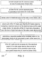
- An electrical power supply method 300 ( FIG. 3 ) of the invention is described below with reference to FIGS. 4 and 5 .
- a first step 302 sunlight is converted into DC electrical power by use of a solar power device.
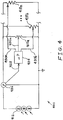
- electrical power supply arrangement 400 ( FIG. 4 ) includes a solar array 412 which converts sunlight into DC electrical power.
- the DC current electrical power is provided to a plurality of adjustable DC loads.
- a plurality of DC loads 418a through 418n each receives and runs on the DC current electrical power generated by solar array 412.
- DC loads 418 may be AC loads.
- a level of electrical output of the solar power device is sensed.
- a power meter 426 or a similar device may sense the output power of solar array 412 and communicate the sensed reading to controller 424, as indicated at 428.
- each of the DC loads is adjusted such that the DC loads conjointly consume a maximum amount of the electrical output of the solar power device.
- the adjusting of the DC loads is dependent upon the level of electrical output of the solar power device.
- controller 424 can adjust each of DC loads 418a-n, as indicated at 430an, such that loads 418a-n in combination consume substantially all of the power that solar array 412 can produce.
- loads 418a-n may represent n number of air conditioning motors each of which is primarily responsible for cooling a respective section of a building.
- loads 418a-n may represent n number of refrigeration and/or ice-making motors.
- the various sections of the building may be at or below the desired set temperature (e.g., 72 degrees F)
- AC motors 418a-n may continue to run during and around the noon hour when sunlight is most direct and thus the output of solar array 412 is greatest.
- the various sections of the building may be "overcooled" to a temperature of approximately between 68 and 71 degrees F, for example.
- AC motors 418a-n may require less electrical power output from solar array 412 in the late afternoon when sunlight is less direct and the electrical power output capability of solar array 412 is lower.
- the building may be efficiently cooled with only small variations in temperature which may not be noticeable to the inhabitants of the building. Also, the variation in the amount of power require from the grid may be reduced, which is highly desirable to the utility companies. Further, by the loads using the full amount of electrical power produced by the solar array, the invention avoids the energy losses associated with converting the DC power from the solar array to AC power, transferring the AC power to the grid, receiving AC power from the grid, and converting the AC power from the grid to DC power.
- a respective portion of the electrical output of the solar power device to be consumed by each of the loads is determined, possibly by use of an algorithm or a lookup table. For example, if DC loads 418a-n represent n number of air conditioning motors cooling respective sections of a building, then each of the sections of the building may be at different actual temperatures, and possibly may have different set temperatures. Thus, controller 424 may adjust air conditioning (or cooling equipment) motors 418a-n such that each motor consumes an amount or portion of electrical power that varies with the difference between the actual temperature and the set temperature of the motor's respective building section.
- the algorithm or lookup table may take into account expected thermal conditions in each of the building sections in the immediate future (e.g., in the next three hours).
- a section on the west side of the building that is more exposed to sunlight may be expected to heat up more in the next few afternoon hours, and thus the respective air conditioning motor may be adjusted to consume a greater portion of the electrical power output of solar array 412.
- the HVAC equipment may no longer operate in a digital fashion as in all on or all off. Instead, the compressor and blower unit may operate at levels consistent with the output of the solar array. When the sun shines strongest, heat loads tend to be highest. The same principle applies to ice-making and refrigeration.
- the step 310 of determining a respective portion of the electrical output of the solar power device to be consumed by each of the loads may include controlling a rate of change of an aggregate consumption of the electrical output of the solar power device by the loads such that the rate of change does not exceed a threshold rate of change.
- the amount of power drawn from solar array 412 may change with a gradual ramp up in order to avoid spikes of power being sent to and/or from the grid. Such spikes may result in inefficiencies and wasted energy.
- controller 424 may adjust loads 418a-n such that a rate of change of power consumption by loads 418a-n does not exceed a threshold or maximum level of Watts per second of time.
- a signal may be sent to the utility advising that the load is planning a gradual ramp and an increased power call from the utility.
- the timing of the ramp may be adjustable based upon a feedback loop (power availability) from the utility.
- Each of the loads may include a respective processor, and the step of determining a respective portion of the electrical output of the solar power device to be consumed by each of the loads may include communication between the processors.
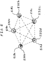
- loads 518a-e each includes a respective one of processors 532a-e.
- processors 532a-e may communicate directly with each of the other ones of processors 532a-e, as indicated by the dashed double-sided arrows in FIG. 5 .
- the communication between processors 532a-e may occur wirelessly, or may be carried by same the electrical conductors that carry power to loads 518a-e.
- processors 532a-e communicate with each other in order to conjunctively determine how much power will be drawn by each of loads 518a-e.
- processors 532a-e may conjunctively determine how much power will be drawn by each of loads 518a-e such that all of the power produced by the solar array is consumed.
- processors 532a-e may conjunctively determine how much power will be drawn by each of loads 518a-e such that a rate of change of power consumption by loads 518a-e does not exceed a threshold or maximum level of Watts per second of time.
- a final step 312 ( FIG. 3 ) if the DC loads cannot consume all of the electrical output of the solar power device, then a remaining portion of the electrical output of the solar power device is converted into AC electrical power.
- processor 424 does not allow one or more the loads 418a-n to consume all the power they are capable of consuming in order to avoid damaging or overheating loads 418a-n.
- processor 424 may not allow one or more the motor to consume all the power they are capable of consuming in order to avoid burning out the motors.
- the remaining portion of the electrical output of solar array 412 may be converted in AC electrical power. This AC electrical power may then be consumed by AC appliances within the building, consumed by full home, commercial building loads, or sent to the grid for use by other consumers.
- electrical power supply arrangement 400 may be substantially similar to those of electrical power supply arrangement 100 as described above, and thus are not further described herein in order to avoid needless repetition.
- FIG. 6 there is illustrated still another embodiment of an electrical power supply arrangement 610 of the present invention including a solar PV array 612, and a DC power bus 614 electrically connecting array 612 to a bidirectional inverter 616 associated with a DC load 618.
- Inverter 616 may convert DC voltage from array 612 to a DC voltage level that is appropriate for use by DC load 618.
- a uni-directional (e.g., one-way) power connector 634 may couple DC load 618 to inverter 616.
- Connector 634 may allow current to flow in only one direction (e.g., from inverter 616 to load 618), and may prevent current from flowing from load 618 to inverter 616 if load 618 happens to function as a generator for a brief period.
- connector 634 may be in the form of one or more diodes (not shown). Thus, uni-directional connector 634 may prevent power from load 618 from damaging inverter 616.
- Array 612 may include a DC-to-DC converter which may convert the DC voltage output by the solar array to a voltage level suitable for transmission on bus 614.
- Inverter 616 may also convert DC voltage from array 612 to an AC voltage that may be used through the remainder of a house 620 with which arrangement 610 is associated. Excess AC power that cannot be used within house 620 may be provided to a grid 622 for use outside of house 620.
- DC voltage from array 612 may be converted to AC voltage by inverter 616 only if HVAC system 618 (or other variable AC or DC loads) cannot consume all of the DC power from array 612.
- a uni-directional (e.g., one-way) power connector 636 may couple array 612 to inverter 616.
- Connector 636 may allow current to flow in only one direction (e.g., from array 612 to inverter 616), and may prevent current from flowing from inverter 616 to array 612.
- connector 636 may be in the form of one or more diodes (not shown). Thus, uni-directional connector 636 may prevent power from inverter 616 from damaging electronics associated with array 612.
- the circulation fan could still run to provide air filtering functionality.
- the compressor could run in a dehumidification mode. Buildings can also be "overcooled” or “overheated” by a slight amount, reducing future energy demand. Thus, by use of these techniques, all of the electrical power produced by the PV may be consumed by the HVAC system.
- the motor speed of the freezer's compressor could be varied to match or completely consume the PV electrical output. Any excess electrical output could be used to "overcool", or further lower, the freezer temperature beyond the temperature that would ordinarily be called for. This allows the thermal energy stored in the freezer to be recovered at night (when there may be no PV electrical output), thereby enabling the freezer to draw a lower level of electrical power from other sources.
- the load can be adjusted to match or completely consume the PV electrical output. Any excess PV electrical output may be used to "overheat" the water above the temperature that would ordinarily be called for. Thus, the need to draw power from other non-PV sources during the day or at night is reduced.
- the pump could be run at variable speed to match or completely consume the PV output. Any extra water that is pumped at a higher motor speed may be stored or deployed during the daytime, thereby reducing the nighttime needs for pumping water.
- the battery charge rate can vary with PV electrical output.
- a DC power bus between the PV system and the DC motor loads may provide an efficient way to vary the load.
- PV modules output DC voltage, so utilizing the DC voltage directly via the DC power bus without conversion to AC voltage may reduce conversion losses.
- a DC input Variable Frequency Drive for an AC motor or DC brushless motor provides an efficient way to vary the speed of a motor and thereby vary the load to match the PV electrical output.
- the DC input Variable Frequency Drive may be employed to vary the amount of work done instead of the conventionally-used on/off cycle or duty cycle.
- a DC input Variable Frequency Drive may be employed in an HVAC system, an irrigation water pump, or a refrigerator, for example.
- the application is applied to HVAC systems on commercial rooftops. Wiring costs and electrical losses may be reduced by directly feeding the PV power into the HVAC rooftop compressor or air handling unit. Losses may be further reduced by utilizing a DC bus to a DC motor.
- PV modules may contain DC/DC converters, with the known inherent benefits of ease of application, flexibility to modify the system to accommodate rooftop changes, tolerance to shadowing, etc.
- Various building electrical loads may be developed to operate off a standardized voltage (e.g. 380VDC), and all loads may be synchronized to PV output via central control to minimize variation in grid demand.
- the invention may beneficially influence electricity consumption via a smart grid.
- the peak power load and the peak power generation by the utility company may be reduced by the invention.
- the invention may realize system synergies.
- the invention may enable the coordination of run times, prevent overloading, and enable the scheduling of events based on the current weather or forecast (e.g., the amount of cloud cover).
- the communication between the solar array and the loads, and the potential communication between the various loads enabled by the invention may enable the homeowner/user/operator to locally and remotely control the user interface.
- the user may control the user interface from his couch within the building, from his work place remotely, or from his vacation home remotely.
- This local and/or remote user control may include reviewing performance data, scheduling operation of appliances based on power cost rates, reviewing billing, and optimizing operation.
- the invention may include features utilized by a professional appliance installer.
- the installer may be provided with an interface for remotely servicing, diagnosing, and/or troubleshooting. This interface may eliminate the need for the installer to make a trip to the job site for troubleshooting.
- the interface may also enable the installer to offer system optimization as a service.
- the invention may enable an appliance manufacturer to optimize the appliance or system remotely.
- the appliance manufacturer may also remotely diagnose the appliance or system to thereby assist the installer.
- the invention may also enable the appliance manufacturer to monitor the performance of the appliance or system, as well as monitor the appliance or system on a long-term basis.
- the invention may provide a central user interface in the form of an existing device that is already familiar to the user, such as an iPhone, television or laptop computer.
- a familiar interface By using a familiar interface, the number of questions from the user is reduced, the number of errors made by the user is reduced, and the user is enabled to have an intuitive interaction with the appliance.
- the invention may operate with a universal open source protocol, such as Zigbee, WLAN, etc.
- a universal open source protocol such as Zigbee, WLAN, etc.
- a gateway with firewall in each appliance or device there may be a high level of operational security may be provided.
- the invention may be integrated in a home network.
- home networks may include the Google power meter or Apple Apps, and/or may be marketed by the Microsoft HomeStore.
- the invention may include a parallel DC network to eliminate DC-to-AC conversion or AC-to-DC conversion. Thus significant losses caused by such conversions may be eliminated.
- the invention has been described in some embodiments above as applying to an HVAC system. However, in other embodiments, the invention is applied to domestic hot water (DHW), building access control/alarm systems/security systems/fire alarms, automobile charging (electric vehicle/plug-in hybrid electric vehicle), kitchen appliances, media, internet, etc.
- DHW domestic hot water
- building access control/alarm systems/security systems/fire alarms building access control/alarm systems/security systems/fire alarms
- automobile charging electric vehicle/plug-in hybrid electric vehicle
- kitchen appliances media, internet, etc.
- the invention has been described above as applying to a DC power source in the form of a solar array. However, in other embodiments, the invention is applied to other sources of DC power, such as the rectified output of a wind turbine, for example.
- the invention may be applied to any DC power source, but may be particularly applicable to a DC power source whose level of DC power output fluctuates with time.
- a bidirectional inverter similar to bidirectional inverter 16 in FIG. 1 , includes a DC solar variable frequency drive (VFD) optimizer.
- VFD DC solar variable frequency drive
- This embodiment may be advantageous with an electric vehicle charger or DC LED lighting being powered on the bus between the solar PV array and the DC VFD optimizer.
- the solar VFD optimizer may remove the need for a solar inverter and may minimize AC cycling on the utility supply (e.g., demand smoothing).
- variable frequency drive used in conjunction with an HVAC
- the speed of rotation may be driven by solar radiation.
- this variable frequency drive to HVAC embodiment may seek constant draw from the utility as opposed to ON/OFF cycling.
- the solar variable frequency drive (VFD) optimizer may enable post-installation changes to the solar configuration, and may enable the use of a high voltage DC power bus, such as could be used with LED lighting and/or EV changing as mentioned above. Also, the solar variable frequency drive (VFD) optimizer embodiment may apply to refrigeration, pumping, etc.
- the invention includes adding smart meter functionality to an HVAC system and motor controller wherein the DC output from a solar array is either directly or through DC/DC converters connected to the DC circuits of the HVAC equipment.
- Utilities and industry have sought to develop and commercial "Smart Meters" that enable utilities control over appliances and energy consuming devices within the home or commercial building. Such meters are costly and in effect replace traditional meters that may be on site. The traditional meters are less expensive and their function is only to measure and report on the amount of energy consumed on the demand side of the meter for billing purposes. Smart meters also provide energy consumption information for billing purposes but allow the utilities to alter the consumption of appliances in the home as required to optimize energy supply and demand.
- Rate payers in exchange for the added cost of the meter may receive special time of day rebates or rate reductions to compensate for their forced or planned reduction in consumption.
- the "control" box on the HVAC may function as a "smart meter” and may provide utilities with all of the functionality that is being built in to “smart meters.”
- a controller of the invention may provide this functionality without having to add another meter to the home.
- the current smart meter concept requires another meter on the home that the utilities are attempting to charge out to their rate payers.
- the solar/HVAC system may have all the features of the smart meter built into the control box.
- the utilities may be able to have all the functionality they want, but there may be no need to add another meter to the home.
- the homeowner may receive energy at lower costs, and the utility may be able to directly monitor HVAC and in-home appliance operation.
- the utility may not need to apply to the utility regulatory commission for rate increases as the utility may not need to bill the homeowner for anything.
- the invention replaces or adds smart meter functionality to the traditional HVAC system and motor controller.
- the utility is able to monitor the building's energy consumption through a traditional meter or a smart meter for billing purposes.
- the utility may monitor and control HVAC and other appliances on the demand side of the meter in a manner consistent with the smart meter approach.
- Smart meter capability may be deployed through the energy transmission infrastructure without the need to have specific charges set aside for a standalone meter as is the current approach.
- the smart meter functionality is built into the HVAC motor controller or another in-house home controller which may include a thermostat, a security system, or other smart appliances. In this manner, utilities may receive smart grid functionality without having to charge out standalone meters to rate payers.
- the invention may provide smart grid functionality to utilities without having to bill rate payers for a standalone smart meter that serves no other purpose.
- the invention may take advantage of incorporating smart grid functionality into other in-building or home systems, meters, controllers that serve other purposes for which the consumer may pay outside of the rate structure.
- the invention may provide the means to commercialize smart grid functionality throughout the transmission and distribution infrastructure for utilities without having to deploy standalone, single purpose smart meters. This may greatly simplify the challenge for regulators who must approve rate increases for utilities in order to pay for the smart meter.
- FIG. 7 is a block diagram of a further embodiment of an electrical power supply arrangement 700 of the present invention including a smart meter 726.
- Electrical power supply arrangement 700 of the present invention also includes a DC load 718 which can be adjusted by a controller 724 to maximize the use of a varying PV output of a solar array 712. That is, smart meter 726 may sense the output power of solar array 712 and communicate the sensed reading to controller 724, as indicated at 728. In turn, controller 724 can adjust DC load 718, as indicated at 730, such that load 718 consumes substantially all of the power that solar array 712 can produce. As indicated by double arrow 732, smart meter 726 may be in bi-directional wired or wireless communication will an electric utility 734. Optionally, smart meter 726 and controller 724 may be disposed in a same housing 736.
Landscapes
- Engineering & Computer Science (AREA)
- Power Engineering (AREA)
- Supply And Distribution Of Alternating Current (AREA)
- Charge And Discharge Circuits For Batteries Or The Like (AREA)
- Dc-Dc Converters (AREA)
- Air Conditioning Control Device (AREA)
- Remote Monitoring And Control Of Power-Distribution Networks (AREA)
- Direct Current Feeding And Distribution (AREA)
- Photovoltaic Devices (AREA)
Description
- The present invention relates to solar power, and, more particularly, to running DC loads by use of solar power.
- Current solar photovoltaic (PV) systems for residential and commercial buildings typically produce direct current (DC) which is inverted to alternating current (AC) using inverters in and connected to an AC circuit breaker box within or on the building.
-
US20030182023A1 discloses a load controller and a method for maximizing effective capacity of PV supply system coupled to a variable AC load (e.g. HVAC). -
US2010274408 A1 discloses a system for balancing energy being consumed by a first device (AC powered HVAC) against the available energy being produced by a second separate device (photovoltaic energy source). -
US2009152947 A1 discloses a power management system for managing the power from solar panels and rechargeable batteries to power a system that includes DC loads and AC loads. -
WO2007018830 A2 andUS2008258470 A1 disclose further related systems. - Such systems suffer from power intermittency caused when the grid must make up any short term reduction in PV output. Current HVAC systems such as heat pumps often utilize AC-to-DC-to-AC, AC motor controls or AC-to-DC power supplies especially when the fans or compressors have variable-speed motors. There are a variety of variable-speed motors which could utilize DC input. Examples are brushless DC motors (BLDC motors) also known as electronically commutated motors (ECM), as well as variable- frequency drives (VFD) for AC motorswhich may also be configured to use DC as the input to the VFD. For example, a Bosch brand geothermal heat pump uses AC-to-DC power supply to power a variable speed ECM fan motor. For the purposes of this invention description, the phrase "DC motor" refers to any motor system where DC is the PV input to the motor or motor controls, even in the case of a DC input VFD controlling a variable speed AC motor or similar.
- It is known to convert all of the DC from PV to AC for use by AC building loads or for export to the utility grid. What is not known in the conventional art is to adjust DC loads such that the DC loads consume a maximum amount of the DC electrical output of the solar panels, and to convert DC power from solar panels to AC only if all of the DC power is not
being consumed by a DC load. Moreover, it is not known to purposefully manage loads, in a variable manner, on the demand side of the meter in concert with the variability of PV power for the purpose of reduction in or avoidance of power intermittency on the grid. Further, it is not known in the conventional art that the DC load is in the form of an HVAC system, such as a heat pump with DC input to the DC phase of AC-DC-AC motor controls. - The invention specified in the appended claims.
- In one embodiment it is directed to an HVAC power supply arrangement in which the DC output from a solar array is either directly or through DC/DC converters connected to the DC circuits of the HVAC equipment. The variable-speed DC motor may be controlled or adjusted to consume a maximum amount of the electrical output of the solar panels, increasing consumption when output is higher, lowering consumption when output is lower. An inverter that is either within (motor control circuits for instance) or separate from the HVAC equipment may operate in a bidirectional mode to invert the DC output from the solar array to AC for the home circuit if the output energy is not being entirely consumed by the variable-speed DC motor. This technique also enables the integration of a DC power bus within the home or commercial building for direct coupling to DC appliances and other DC devices.
- In one embodiment, the invention comprises an electrical power supply arrangement including a solar power device that converts sunlight into DC electrical power. An adjustable DC load runs on the DC current electrical power. An electrical output sensing device senses a level of electrical output of the solar power device. A controller is coupled to each of the adjustable DC loads and the electrical output sensing device. The controller receives a signal from the electrical output sensing device, and adjusts the DC load such that the DC loads consumes substantially all of the electrical output of the solar power device. The adjusting of the DC loads is performed dependent upon the received signal, and depending on which other loads need to receive power. For example, it may be determined how much of the available solar-generated electricity should be sent to the HVAC systems and how much should be sent to other loads, such as a charging station for an Electric Vehicle (EV).
- In another embodiment, the invention comprises an electrical power supply arrangement including a solar power device that converts sunlight into DC electrical power. A DC load runs on the DC current electrical power. A DC-to-AC converter converts the DC electrical power into AC electrical power. A controller enables the DC-to-AC converter to receive a portion of the DC current electrical power from the solar power device only if all of the DC current electrical power cannot be consumed by the DC load.
- In yet another embodiment, the invention comprises an electrical power supply method including converting sunlight into DC electrical power by use of a solar power device. The DC current electrical power is provided to a plurality of adjustable DC loads. A level of electrical output of the solar power device is sensed. Each of the DC loads is adjusted such that the DC loads conjointly consume a maximum amount of the electrical output of the solar power device. The adjusting of the DC loads is dependent upon the level of electrical output of the solar power device.
- In yet another embodiment, the invention comprises an electrical power supply method including converting sunlight into DC electrical power by use of a solar power device. The DC current electrical power is provided to an inverter to provide power to an AC load. A level of electrical output of the solar power device is sensed. The AC load or series of AC loads are operated in a variable fashion that optimizes the consumption of the variable PV DC electrical power in a manner which intends to eliminate or reduce AC power demands from the utility grid. The adjusting of the AC loads is dependent upon the level of electrical output of the solar power device.
- The invention may eliminate the need to have an inverter between the photovoltaic (PV) system and the circuit breaker box. Instead, the DC output from the solar array may be either directly, or through DC/DC converters, connected to the DC circuits of the HVAC equipment. The inverter within the HVAC equipment then may act in a bidirectional mode to invert the DC from the solar array to AC for the home circuit or utility grid, if the output energy is not being entirely consumed by the variable-speed DC motor or other DC loads in the building. This technique also enables the integration of a DC power bus within the home or commercial building for direct coupling to DC appliances and other DC devices. The elimination of the traditional inverter conventionally used for solar systems may greatly reduce system cost, reduce electrical losses due to the inversion, and may result in increased system efficiency at lower cost. The invention may achieve the lower cost, higher efficiency, and higher reliability through simplification of the system.
- In another embodiment, electrical DC loads (e.g., HVAC systems, appliances, EV chargers, water pumps, etc.) are adjusted in a variable manner such that the power consumption of the loads corresponds as closely as possible to the power available from a PV system. This adjustment of the DC loads is intended to result in less variation in the demand on other power sources in the system (e.g., the utility grid, battery, etc.) by the DC loads. In such applications, the PV output is designed to provide adequate power to the load without call for additional power from the utility or storage device. Utility or storage power is intended to only provide power during evenings or emergencies. This adjustment of the DC loads may also reduce system losses, minimize utility transformer size, lower system costs, and increase the ability of the utility grid to support higher penetration levels of renewable energy. Such application allows the utilities to avoid the added costs of spinning reserves for the purpose of managing the power intermittency caused by traditional PV system designs.
- In still another embodiment, the invention is directed to adding smart meter functionality to an HVAC system and motor controller wherein the DC output from a solar array is either directly or through DC/DC converters connected to the DC circuits of the HVAC equipment. An inverter within the HVAC equipment operates in a bidirectional mode to invert the DC from the solar array to AC for the home circuit if the output energy cannot be consumed by the variable-speed DC motor. The utility is able to monitor and control HVAC and other appliances on the demand side of the meter. The smart meter functionality is built into the HVAC motor controller or another in-house home controller potentially including the thermostat, the security system, or other smart appliances. In this manner, smart grid functionality is provided without having to provide a standalone meter.
- In a further embodiment, the invention comprises an electrical power supply arrangement including a solar power device converting sunlight into DC electrical power. An adjustable DC load runs on the DC current electrical power. An electrical output sensing device senses a level of electrical output of the solar power device. A local controller is coupled to each of the adjustable DC load and the electrical output sensing device. A remote controller is communicatively coupled to the local controller and is disposed at a location remote from the adjustable DC load. The remote controller communicates via the local controller to thereby receive a signal from the electrical output sensing device, and adjust the DC loads such that the DC loads consumes a maximum amount of the electrical output of the solar power device, the adjusting of the DC load being dependent upon the received signal. If the DC load cannot consume all of the electrical output of the solar power device, then the remote controller causes a remaining portion of the electrical output of the solar power device to be converted into AC electrical power.
- The above mentioned and other features and objects of this invention, and the manner of attaining them, will become more apparent and the invention itself will be better understood by reference to the following description of embodiments of the invention taken in conjunction with the accompanying drawings, wherein:
-
FIG. 1 is a block diagram of one embodiment of an electrical power supply arrangement of the present invention. -
FIG. 2 is a block diagram of another embodiment of an electrical power supply arrangement of the present invention. -
FIG. 3 is a flow chart of one embodiment of an electrical power supply method of the present invention. -
FIG. 4 is a block diagram of yet another embodiment of an electrical power supply arrangement of the present invention. -
FIG. 5 is a diagram illustrating communication between DC loads according to another embodiment of an electrical power supply method of the present invention. -
FIG. 6 is a block diagram of still another embodiment of an electrical power supply arrangement of the present invention. -
FIG. 7 is a block diagram of a further embodiment of an electrical power supply arrangement of the present invention. - Corresponding reference characters indicate corresponding parts throughout the several views. Although the exemplification set out herein illustrates embodiments of the invention, in several forms, the embodiments disclosed below are not intended to be exhaustive or to be construed as limiting the scope of the invention to the precise forms disclosed.
- Referring now to the drawings, and particularly to
FIG. 1 , there is illustrated one embodiment of an electricalpower supply arrangement 10 of the present invention including asolar PV array 12, and aDC power bus 14 electrically connectingarray 12 to abidirectional inverter 16 of an HVAC system 18 (or DC input to the DC phase in an AC-DC-AC motor controller circuit).Inverter 16 may convert DC voltage fromarray 12 to a DC voltage level that is appropriate for use byHVAC system 18.Array 12 may include a DC-to-DC converter which may convert the DC voltage output by the solar array to a voltage level suitable for transmission onbus 14.Inverter 16 may also convert DC voltage fromarray 12 to an AC voltage that may be used through the remainder of a house 20 with whicharrangement 10 is associated. Excess AC power that cannot be used within house 20 may be provided to agrid 22 for use outside of house 20. In one embodiment, DC voltage fromarray 12 may be converted to AC voltage byinverter 16 only if HVAC system 18 (or other variable AC or DC loads) cannot consume all of the DC power fromarray 12. - By transferring the DC voltage from
array 12 directly toHVAC system 18,arrangement 10 may eliminate the need for a separate inverter to convert the DC voltage fromarray 12 to AC voltage for transmission and use by both AC loads and DC loads (after conversion of the AC voltage back to DC voltage). The omission of the separate inverter may reduce electrical losses, reduce cost, and provide improved reliability of the system. Moreover, the invention may provide a high voltageDC power bus 14 which may be used by other appliances within the building or EV charging systems. - In another embodiment, the bidirectional inverter may simply be a DC drive or DC motor, and an optional, often smaller, inverter may be added to the DC bus. The need for an inverter and the size of the inverter may be determined by the amount of PV energy, if any, that could not be consumed by the DC loads under certain building circumstances.
- In an alternative embodiment (not shown), the DC/DC conversion at
PV array 12 is omitted. That is, the DC voltage may be transmitted onbus 14 in the same voltage as produced by the solar cells ofarray 12. - In another embodiment (
FIG. 2 ), an electrical power supply arrangement 100 of the present invention includes aDC load 118 which can be adjusted by acontroller 124 to maximize the use of a varying PV output of asolar array 112. That is, apower meter 126 or a similar device may sense the output power ofsolar array 112 and communicate the sensed reading tocontroller 124, as indicated at 128. In turn,controller 124 can adjustDC load 118, as indicated at 130, such thatload 118 consumes substantially all of the power thatsolar array 112 can produce. Thus, no inverter, or a reduced size inverter, may be needed to feed excess PV output into the utility grid (not shown). A practical example would be to run air conditioning motors at lower speed for a longer time under the reduced solar power output of lower light (e.g., cloudy) conditions. This could achieve the same building cooling, while reducing the variation (intermittency) of power on the grid, which is highly desirable to the utility companies. Also, by the load(s) using the entire amount of electrical power produced by the solar array, the invention avoids the energy losses associated with converting the DC power from the solar array to AC power, transferring the AC power to the grid, receiving AC power from the grid, and converting the AC power from the grid to DC power. - The same principle may apply to systems utilizing battery storage in place of, or in addition to, solar arrays. In this case, the battery controller and/or charge controller could be reduced or eliminated by adjusting the load to consume all of the power output of the battery. In one embodiment, the battery ensures that a minimum required level of electrical power may be provided to the load when the solar array cannot provide the minimum required level of electrical power. For example, the battery may power the electronic controller as well as any electronics operating in association with the load. For example, a battery may keep lights operating on the load at night so that a user can interact with the load, even though the solar array cannot provide power to keep the load fully operating until daylight in the morning. The battery may be recharged by the solar array in the event that the solar array produces more power than is required by the load. In addition, synchronizing the loads to the available solar energy could reduce the amount and frequency of charging and discharging batteries in the system which may extend the battery life. Solar Synchronized Loads can also improve battery life by reducing the intermittency in battery charging/discharging in the same way as intermittency in utility grid demand is reduced.
- An electrical power supply method 300 (
FIG. 3 ) of the invention is described below with reference toFIGS. 4 and5 . In a first step 302, sunlight is converted into DC electrical power by use of a solar power device. For example, electrical power supply arrangement 400 (FIG. 4 ) includes asolar array 412 which converts sunlight into DC electrical power. - In a next step 304, the DC current electrical power is provided to a plurality of adjustable DC loads. As shown in the specific embodiment of
FIG. 4 , a plurality of DC loads 418a through 418n each receives and runs on the DC current electrical power generated bysolar array 412. Alternatively, DC loads 418 may be AC loads. - Next, in
step 306, a level of electrical output of the solar power device is sensed. For example, apower meter 426 or a similar device may sense the output power ofsolar array 412 and communicate the sensed reading tocontroller 424, as indicated at 428. - In step 308, each of the DC loads is adjusted such that the DC loads conjointly consume a maximum amount of the electrical output of the solar power device. The adjusting of the DC loads is dependent upon the level of electrical output of the solar power device. In the example embodiment of
FIG. 4 ,controller 424 can adjust each of DC loads 418a-n, as indicated at 430an, such that loads 418a-n in combination consume substantially all of the power thatsolar array 412 can produce. Thus, no inverter, or a reduced size inverter, may be needed to feed excess PV output into the utility grid (not shown). For example, loads 418a-n may represent n number of air conditioning motors each of which is primarily responsible for cooling a respective section of a building. In an alternative embodiment, loads 418a-n may represent n number of refrigeration and/or ice-making motors. Although the various sections of the building may be at or below the desired set temperature (e.g., 72 degrees F), AC motors 418a-n may continue to run during and around the noon hour when sunlight is most direct and thus the output ofsolar array 412 is greatest. Thereby, the various sections of the building may be "overcooled" to a temperature of approximately between 68 and 71 degrees F, for example. By virtue of such overcooling, AC motors 418a-n may require less electrical power output fromsolar array 412 in the late afternoon when sunlight is less direct and the electrical power output capability ofsolar array 412 is lower. Thus, the building may be efficiently cooled with only small variations in temperature which may not be noticeable to the inhabitants of the building. Also, the variation in the amount of power require from the grid may be reduced, which is highly desirable to the utility companies. Further, by the loads using the full amount of electrical power produced by the solar array, the invention avoids the energy losses associated with converting the DC power from the solar array to AC power, transferring the AC power to the grid, receiving AC power from the grid, and converting the AC power from the grid to DC power. - In a
next step 310, a respective portion of the electrical output of the solar power device to be consumed by each of the loads is determined, possibly by use of an algorithm or a lookup table. For example, if DC loads 418a-n represent n number of air conditioning motors cooling respective sections of a building, then each of the sections of the building may be at different actual temperatures, and possibly may have different set temperatures. Thus,controller 424 may adjust air conditioning (or cooling equipment) motors 418a-n such that each motor consumes an amount or portion of electrical power that varies with the difference between the actual temperature and the set temperature of the motor's respective building section. The algorithm or lookup table may take into account expected thermal conditions in each of the building sections in the immediate future (e.g., in the next three hours). For example, a section on the west side of the building that is more exposed to sunlight may be expected to heat up more in the next few afternoon hours, and thus the respective air conditioning motor may be adjusted to consume a greater portion of the electrical power output ofsolar array 412. Generally, the HVAC equipment may no longer operate in a digital fashion as in all on or all off. Instead, the compressor and blower unit may operate at levels consistent with the output of the solar array. When the sun shines strongest, heat loads tend to be highest. The same principle applies to ice-making and refrigeration. - The
step 310 of determining a respective portion of the electrical output of the solar power device to be consumed by each of the loads may include controlling a rate of change of an aggregate consumption of the electrical output of the solar power device by the loads such that the rate of change does not exceed a threshold rate of change. Thus, the amount of power drawn fromsolar array 412 may change with a gradual ramp up in order to avoid spikes of power being sent to and/or from the grid. Such spikes may result in inefficiencies and wasted energy. For example,controller 424 may adjust loads 418a-n such that a rate of change of power consumption by loads 418a-n does not exceed a threshold or maximum level of Watts per second of time. If the load requires more energy than can be delivered from the array, a signal may be sent to the utility advising that the load is planning a gradual ramp and an increased power call from the utility. The timing of the ramp may be adjustable based upon a feedback loop (power availability) from the utility. - Each of the loads may include a respective processor, and the step of determining a respective portion of the electrical output of the solar power device to be consumed by each of the loads may include communication between the processors. For example, as shown in
FIG. 5 , loads 518a-e each includes a respective one ofprocessors 532a-e. Each ofprocessors 532a-e may communicate directly with each of the other ones ofprocessors 532a-e, as indicated by the dashed double-sided arrows inFIG. 5 . The communication betweenprocessors 532a-e may occur wirelessly, or may be carried by same the electrical conductors that carry power toloads 518a-e. In one embodiment,processors 532a-e communicate with each other in order to conjunctively determine how much power will be drawn by each ofloads 518a-e. For example,processors 532a-e may conjunctively determine how much power will be drawn by each ofloads 518a-e such that all of the power produced by the solar array is consumed. Alternatively, or in addition,processors 532a-e may conjunctively determine how much power will be drawn by each ofloads 518a-e such that a rate of change of power consumption byloads 518a-e does not exceed a threshold or maximum level of Watts per second of time. - In a final step 312 (
FIG. 3 ), if the DC loads cannot consume all of the electrical output of the solar power device, then a remaining portion of the electrical output of the solar power device is converted into AC electrical power. There may also be situations in which the load 418a-n are capable, strictly speaking, of consuming all of the electrical output of thesolar power device 412, butprocessor 424 does not allow one or more the loads 418a-n to consume all the power they are capable of consuming in order to avoid damaging or overheating loads 418a-n. In the above-described embodiment including loads in the form of air conditioning motors,processor 424 may not allow one or more the motor to consume all the power they are capable of consuming in order to avoid burning out the motors. Regardless of whether the loads are physically incapable of consuming all of the electrical output of the solar power device or the processor prevents the loads from consuming all of the electrical output of the solar power device strictly to avoid damaging the loads, the remaining portion of the electrical output ofsolar array 412 may be converted in AC electrical power. This AC electrical power may then be consumed by AC appliances within the building, consumed by full home, commercial building loads, or sent to the grid for use by other consumers. - Other features of electrical
power supply arrangement 400 may be substantially similar to those of electrical power supply arrangement 100 as described above, and thus are not further described herein in order to avoid needless repetition. - In
FIG. 6 there is illustrated still another embodiment of an electricalpower supply arrangement 610 of the present invention including asolar PV array 612, and aDC power bus 614 electrically connectingarray 612 to abidirectional inverter 616 associated with aDC load 618.Inverter 616 may convert DC voltage fromarray 612 to a DC voltage level that is appropriate for use byDC load 618. A uni-directional (e.g., one-way)power connector 634 may coupleDC load 618 toinverter 616.Connector 634 may allow current to flow in only one direction (e.g., frominverter 616 to load 618), and may prevent current from flowing fromload 618 toinverter 616 ifload 618 happens to function as a generator for a brief period. In one embodiment,connector 634 may be in the form of one or more diodes (not shown). Thus,uni-directional connector 634 may prevent power fromload 618 fromdamaging inverter 616. -
Array 612 may include a DC-to-DC converter which may convert the DC voltage output by the solar array to a voltage level suitable for transmission onbus 614.Inverter 616 may also convert DC voltage fromarray 612 to an AC voltage that may be used through the remainder of a house 620 with whicharrangement 610 is associated. Excess AC power that cannot be used within house 620 may be provided to agrid 622 for use outside of house 620. In one embodiment, DC voltage fromarray 612 may be converted to AC voltage byinverter 616 only if HVAC system 618 (or other variable AC or DC loads) cannot consume all of the DC power fromarray 612. A uni-directional (e.g., one-way)power connector 636 may couplearray 612 toinverter 616.Connector 636 may allow current to flow in only one direction (e.g., fromarray 612 to inverter 616), and may prevent current from flowing frominverter 616 toarray 612. In one embodiment,connector 636 may be in the form of one or more diodes (not shown). Thus,uni-directional connector 636 may prevent power frominverter 616 from damaging electronics associated witharray 612. - As the invention may be applied to an HVAC system as the load, if heating or cooling is not needed while the PV electrical output is available, the circulation fan could still run to provide air filtering functionality. Similarly, the compressor could run in a dehumidification mode. Buildings can also be "overcooled" or "overheated" by a slight amount, reducing future energy demand. Thus, by use of these techniques, all of the electrical power produced by the PV may be consumed by the HVAC system.
- As the invention may be applied to a freezer or refrigerator as the load, the motor speed of the freezer's compressor could be varied to match or completely consume the PV electrical output. Any excess electrical output could be used to "overcool", or further lower, the freezer temperature beyond the temperature that would ordinarily be called for. This allows the thermal energy stored in the freezer to be recovered at night (when there may be no PV electrical output), thereby enabling the freezer to draw a lower level of electrical power from other sources.
- As the invention may be applied to a heat pump or conventional electric hot water heater as the load, the load can be adjusted to match or completely consume the PV electrical output. Any excess PV electrical output may be used to "overheat" the water above the temperature that would ordinarily be called for. Thus, the need to draw power from other non-PV sources during the day or at night is reduced.
- As the invention may be applied to a water pump as the load, the pump could be run at variable speed to match or completely consume the PV output. Any extra water that is pumped at a higher motor speed may be stored or deployed during the daytime, thereby reducing the nighttime needs for pumping water.
- As the invention may be applied to electric vehicle charging as the load, the battery charge rate can vary with PV electrical output. A DC power bus between the PV system and the DC motor loads may provide an efficient way to vary the load. PV modules output DC voltage, so utilizing the DC voltage directly via the DC power bus without conversion to AC voltage may reduce conversion losses.
- In one embodiment, a DC input Variable Frequency Drive (VFD) for an AC motor or DC brushless motor provides an efficient way to vary the speed of a motor and thereby vary the load to match the PV electrical output. The DC input Variable Frequency Drive may be employed to vary the amount of work done instead of the conventionally-used on/off cycle or duty cycle. A DC input Variable Frequency Drive may be employed in an HVAC system, an irrigation water pump, or a refrigerator, for example.
- In one embodiment, the application is applied to HVAC systems on commercial rooftops. Wiring costs and electrical losses may be reduced by directly feeding the PV power into the HVAC rooftop compressor or air handling unit. Losses may be further reduced by utilizing a DC bus to a DC motor.
- The principle of solar synchronized DC loads may be applied to standardized DC building bus systems (e.g., the emerging 380VDC standard). In one embodiment, PV modules may contain DC/DC converters, with the known inherent benefits of ease of application, flexibility to modify the system to accommodate rooftop changes, tolerance to shadowing, etc. Various building electrical loads may be developed to operate off a standardized voltage (e.g. 380VDC), and all loads may be synchronized to PV output via central control to minimize variation in grid demand.
- The invention may beneficially influence electricity consumption via a smart grid. For example, the peak power load and the peak power generation by the utility company may be reduced by the invention.
- In another aspect, the invention may realize system synergies. For example, the invention may enable the coordination of run times, prevent overloading, and enable the scheduling of events based on the current weather or forecast (e.g., the amount of cloud cover).
- In another aspect, the communication between the solar array and the loads, and the potential communication between the various loads enabled by the invention may enable the homeowner/user/operator to locally and remotely control the user interface. For example, the user may control the user interface from his couch within the building, from his work place remotely, or from his vacation home remotely. This local and/or remote user control may include reviewing performance data, scheduling operation of appliances based on power cost rates, reviewing billing, and optimizing operation.
- In another aspect, the invention may include features utilized by a professional appliance installer. For example, the installer may be provided with an interface for remotely servicing, diagnosing, and/or troubleshooting. This interface may eliminate the need for the installer to make a trip to the job site for troubleshooting. The interface may also enable the installer to offer system optimization as a service.
- In still another aspect, the invention may enable an appliance manufacturer to optimize the appliance or system remotely. The appliance manufacturer may also remotely diagnose the appliance or system to thereby assist the installer. The invention may also enable the appliance manufacturer to monitor the performance of the appliance or system, as well as monitor the appliance or system on a long-term basis.
- In a further aspect, the invention may provide a central user interface in the form of an existing device that is already familiar to the user, such as an iPhone, television or laptop computer. By using a familiar interface, the number of questions from the user is reduced, the number of errors made by the user is reduced, and the user is enabled to have an intuitive interaction with the appliance.
- In a still further aspect, the invention may operate with a universal open source protocol, such as Zigbee, WLAN, etc. Thus, interaction with other devices may be enabled.
- In another aspect of the invention, there may be a gateway with firewall in each appliance or device. Thus, a high level of operational security may be provided.
- In yet another aspect, the invention may be integrated in a home network. Such home networks may include the Google power meter or Apple Apps, and/or may be marketed by the Microsoft HomeStore.
- In a further aspect, the invention may include a parallel DC network to eliminate DC-to-AC conversion or AC-to-DC conversion. Thus significant losses caused by such conversions may be eliminated.
- The invention has been described in some embodiments above as applying to an HVAC system. However, in other embodiments, the invention is applied to domestic hot water (DHW), building access control/alarm systems/security systems/fire alarms, automobile charging (electric vehicle/plug-in hybrid electric vehicle), kitchen appliances, media, internet, etc.
- The invention has been described above as applying to a DC power source in the form of a solar array. However, in other embodiments, the invention is applied to other sources of DC power, such as the rectified output of a wind turbine, for example. The invention may be applied to any DC power source, but may be particularly applicable to a DC power source whose level of DC power output fluctuates with time.
- In another embodiment, a bidirectional inverter, similar to
bidirectional inverter 16 inFIG. 1 , includes a DC solar variable frequency drive (VFD) optimizer. This embodiment may be advantageous with an electric vehicle charger or DC LED lighting being powered on the bus between the solar PV array and the DC VFD optimizer. The solar VFD optimizer may remove the need for a solar inverter and may minimize AC cycling on the utility supply (e.g., demand smoothing). - With a variable frequency drive used in conjunction with an HVAC, the speed of rotation may be driven by solar radiation. Also, there may be longer cycles if necessary to offset slower compressor rotation. Further, this variable frequency drive to HVAC embodiment may seek constant draw from the utility as opposed to ON/OFF cycling.
- The solar variable frequency drive (VFD) optimizer may enable post-installation changes to the solar configuration, and may enable the use of a high voltage DC power bus, such as could be used with LED lighting and/or EV changing as mentioned above. Also, the solar variable frequency drive (VFD) optimizer embodiment may apply to refrigeration, pumping, etc.
- In another embodiment, the invention includes adding smart meter functionality to an HVAC system and motor controller wherein the DC output from a solar array is either directly or through DC/DC converters connected to the DC circuits of the HVAC equipment. Utilities and industry have sought to develop and commercial "Smart Meters" that enable utilities control over appliances and energy consuming devices within the home or commercial building. Such meters are costly and in effect replace traditional meters that may be on site. The traditional meters are less expensive and their function is only to measure and report on the amount of energy consumed on the demand side of the meter for billing purposes. Smart meters also provide energy consumption information for billing purposes but allow the utilities to alter the consumption of appliances in the home as required to optimize energy supply and demand. Smart meter commercialization attempts have proposed rate increases to the rate payers to cover the expense of adding smart meters to the home and commercial buildings. Rate payers in exchange for the added cost of the meter, may receive special time of day rebates or rate reductions to compensate for their forced or planned reduction in consumption.
- In effect, the "control" box on the HVAC may function as a "smart meter" and may provide utilities with all of the functionality that is being built in to "smart meters." There is significant investment being made in smart meters and their primary purpose is to allow utilities to go into the home and control appliances/consumption. A controller of the invention may provide this functionality without having to add another meter to the home. The current smart meter concept requires another meter on the home that the utilities are attempting to charge out to their rate payers. According to the invention, the solar/HVAC system may have all the features of the smart meter built into the control box. The utilities may be able to have all the functionality they want, but there may be no need to add another meter to the home. The homeowner may receive energy at lower costs, and the utility may be able to directly monitor HVAC and in-home appliance operation. Thus, the utility may not need to apply to the utility regulatory commission for rate increases as the utility may not need to bill the homeowner for anything.
- The invention replaces or adds smart meter functionality to the traditional HVAC system and motor controller. The utility is able to monitor the building's energy consumption through a traditional meter or a smart meter for billing purposes. In addition, the utility may monitor and control HVAC and other appliances on the demand side of the meter in a manner consistent with the smart meter approach. Smart meter capability may be deployed through the energy transmission infrastructure without the need to have specific charges set aside for a standalone meter as is the current approach. The smart meter functionality is built into the HVAC motor controller or another in-house home controller which may include a thermostat, a security system, or other smart appliances. In this manner, utilities may receive smart grid functionality without having to charge out standalone meters to rate payers.
- The invention may provide smart grid functionality to utilities without having to bill rate payers for a standalone smart meter that serves no other purpose. The invention may take advantage of incorporating smart grid functionality into other in-building or home systems, meters, controllers that serve other purposes for which the consumer may pay outside of the rate structure.
- The invention may provide the means to commercialize smart grid functionality throughout the transmission and distribution infrastructure for utilities without having to deploy standalone, single purpose smart meters. This may greatly simplify the challenge for regulators who must approve rate increases for utilities in order to pay for the smart meter.
-
FIG. 7 is a block diagram of a further embodiment of an electricalpower supply arrangement 700 of the present invention including asmart meter 726. Electricalpower supply arrangement 700 of the present invention also includes aDC load 718 which can be adjusted by acontroller 724 to maximize the use of a varying PV output of asolar array 712. That is,smart meter 726 may sense the output power ofsolar array 712 and communicate the sensed reading tocontroller 724, as indicated at 728. In turn,controller 724 can adjustDC load 718, as indicated at 730, such thatload 718 consumes substantially all of the power thatsolar array 712 can produce. As indicated bydouble arrow 732,smart meter 726 may be in bi-directional wired or wireless communication will anelectric utility 734. Optionally,smart meter 726 andcontroller 724 may be disposed in asame housing 736. - While this invention has been described as having an exemplary design, the present invention may be further modified within scope of this disclosure. This application is therefore intended to cover any variations, uses, or adaptations of the invention using its general principles
Claims (19)
- An electrical power supply method, comprising the steps of:converting (302) sunlight into DC electrical power by use of a solar power device (112, 412, 712);providing (304) the DC electrical power to a plurality of adjustable DC loads (118, 418a, ..., 418n, 718);sensing (306) a level of electrical output of the solar power device (112, 412, 712); andadjusting each of the plurality of adjustable_DC loads (118, 418a, ..., 418n, 718) such that the plurality of adjustable_DC loads (118, 418a, ..., 418n, 718) conjointly consume a maximum amount of the electrical output of the solar power device (112, 412, 712), the adjusting of each of_the adjustable_DC loads (118, 418a, ..., 418n, 718) being dependent upon the level of electrical output of the solar power device (112, 412, 712) ; andif the DC loads (118, 418a, ..., 418n, 718) cannot consume all of the electrical output of the solar power device (112, 412, 712), converting (312) a remaining portion of the electrical output of the solar power device (112, 412, 712) into AC electrical power
- The method of Claim 1 comprising the further step of determining (310) a respective portion of the electrical output of the solar power device (112, 412, 712) to be consumed by each of the plurality of adjustable DC_loads (118, 418a, ..., 418n, 718).
- The method of Claim 2 wherein the determining step is performed by use of an algorithm or a lookup table.
- The method of Claim 2 wherein the determining step (310) includes controlling a rate of change of an aggregate consumption of the electrical output of the solar power device by the plurality of adjustable DC_loads such that the rate of change does not exceed a threshold rate of change.
- The method of Claim 2 wherein each of the plurality of adjustable DC_loads includes a processor, the determining step (310) including the processors of each of_the plurality of adjustable DC_loads communicating with each other.
- An electrical power supply arrangement (100, 400, 700) comprising:a solar power device (112, 412, 712) configured to convert sunlight into DC electrical power;a DC load (118, 418a, ..., 418n, 718) configured to run on the DC electrical power;a DC-to-AC converter configured to convert the DC electrical power into AC electrical power; anda controller (124, 424, 724) configured to enable the DC-to-AC converter to receive a portion of the DC electrical power from the solar power device (112, 412, 712) only if all of the DC electrical power cannot be consumed by the DC load (118, 418a, ..., 418n, 718).
- The arrangement of Claim 6 wherein the solar power device (112, 412, 712) comprises a solar photovoltaic device.
- The arrangement of Claim 6 further comprising an AC-to-DC power supply configured to supply DC electrical power to the DC load (118, 418a, ..., 418n, 718) if sunlight is not available to the solar power device (112, 412, 712).
- The arrangement of Claim 6 further comprising a DC power bus interconnecting the solar power device (112, 412, 712) and the DC load (118, 418a, ..., 418n, 718).
- The arrangement of Claim 6 wherein the DC load (118, 418a, ..., 418n, 718) comprises an appliance.
- The arrangement of Claim 10 wherein the appliance comprises HVAC equipment.
- The arrangement of Claim 6, further comprising an electrical output sensing device configured to sense a level of electrical output of the solar power device, wherein the DC load is an adjustable DC load and wherein the controller is coupled to the adjustable DC load and the electrical output sensing device, the controller being configured to:receive a signal from the electrical output sensing device; andadjust the adjustable DC load such that the adjustable DC load consumes a maximum amount of the electrical output of the solar power device, the adjusting of the adjustable DC load being dependent upon the received signal.
- The arrangement of Claim 12, wherein the controller is a remote controller disposed at a location remote from the adjustable DC load, the remote controller being communicatively coupled to a local controller, the local controller coupled to the adjustable DC load and the electrical output sensing device, the remote controller being configured to communicate via the local controller to receive the signal from the electrical output sensing device, adjust the adjustable DC load such that the adjustable DC load consumes a maximum amount of the electrical output of the solar power device, and enable the DC-to-AC converter to receive a portion of the DC electrical power from the solar power device only if all of the DC electrical power cannot be consumed by the adjustable DC load.
- The arrangement of Claim 12, wherein the electrical output sensing device comprises a power meter.
- The arrangement of Claim 12, wherein the adjustable DC load comprises an HVAC system.
- The arrangement of Claim 15, wherein the HVAC system comprises a circulation fan, the controller being configured to use power from the solar power device to operate the circulation fan while heating and cooling is not needed.
- The arrangement of Claim 15, wherein the HVAC system comprises a compressor, the controller being configured to use power from the solar power device to operate the compressor in a dehumidification mode while heating and cooling is not needed.
- The arrangement of Claim 15, wherein the controller is configured to use power from the solar power device to perform overheating or overcooling with the HVAC system beyond a set temperature of the HVAC system, the set temperature having been set by a human user.
- The arrangement of Claim 6, further comprising a battery configured to supplement the DC electrical power provided by the solar power device.
Applications Claiming Priority (4)
| Application Number | Priority Date | Filing Date | Title |
|---|---|---|---|
| US201161525483P | 2011-08-19 | 2011-08-19 | |
| US13/489,412 US20130043723A1 (en) | 2011-08-19 | 2012-06-05 | Solar synchronized loads for photovoltaic systems |
| US13/560,726 US8373303B1 (en) | 2011-08-19 | 2012-07-27 | Solar synchronized loads for photovoltaic systems |
| PCT/US2012/051639 WO2013028644A2 (en) | 2011-08-19 | 2012-08-20 | Solar synchronized loads for photovoltaic systems |
Publications (2)
| Publication Number | Publication Date |
|---|---|
| EP2745371A2 EP2745371A2 (en) | 2014-06-25 |
| EP2745371B1 true EP2745371B1 (en) | 2019-03-27 |
Family
ID=47631958
Family Applications (1)
| Application Number | Title | Priority Date | Filing Date |
|---|---|---|---|
| EP12762440.1A Revoked EP2745371B1 (en) | 2011-08-19 | 2012-08-20 | Solar synchronized loads for photovoltaic systems |
Country Status (7)
| Country | Link |
|---|---|
| US (4) | US20130043723A1 (en) |
| EP (1) | EP2745371B1 (en) |
| JP (2) | JP2014531882A (en) |
| KR (1) | KR20140064871A (en) |
| CN (1) | CN104040829B (en) |
| CA (1) | CA2845565A1 (en) |
| WO (1) | WO2013028644A2 (en) |
Families Citing this family (53)
| Publication number | Priority date | Publication date | Assignee | Title |
|---|---|---|---|---|
| US8640799B2 (en) * | 2009-06-11 | 2014-02-04 | Illinois Tool Works Inc. | Welding systems powered by hybrid vehicles |
| US20120136500A1 (en) * | 2009-08-06 | 2012-05-31 | Rodney Hughes | Operator interface for automation systems |
| US20130043723A1 (en) * | 2011-08-19 | 2013-02-21 | Robert Bosch Gmbh | Solar synchronized loads for photovoltaic systems |
| US9218035B2 (en) * | 2012-02-10 | 2015-12-22 | University Of Florida Research Foundation, Inc. | Renewable energy control systems and methods |
| US9455572B2 (en) * | 2012-04-27 | 2016-09-27 | Marvin A Motsenbocker | Voltage prioritization of solar loads |
| US9105765B2 (en) | 2012-12-18 | 2015-08-11 | Enphase Energy, Inc. | Smart junction box for a photovoltaic system |
| US10144083B2 (en) | 2013-02-22 | 2018-12-04 | Illinois Tool Works Inc. | Multi-operator engine driven welder system |
| DE102013004065A1 (en) * | 2013-03-11 | 2014-09-11 | Stiebel Eltron Gmbh & Co. Kg | Heat pump systems with energy supply |
| CZ304509B6 (en) * | 2013-04-25 | 2014-06-04 | Unites Systems A.S. | System for managing electric power produced by photovoltaic cells |
| CN103486682B (en) * | 2013-09-25 | 2021-09-28 | 珠海格力电器股份有限公司 | Photovoltaic air conditioning system |
| WO2015051155A1 (en) | 2013-10-02 | 2015-04-09 | Enphase Energy, Inc. | Method and apparatus for controlling power based on predicted weather events |
| JP2015089320A (en) * | 2013-11-01 | 2015-05-07 | ソニー株式会社 | Power storage system and control method thereof |
| CN104734553B (en) * | 2013-12-24 | 2018-02-27 | 珠海格力电器股份有限公司 | converter, photovoltaic power generation system and control method thereof |
| CN107749636A (en) * | 2013-12-24 | 2018-03-02 | 珠海格力电器股份有限公司 | Ternary converter system based on distributed power generation system |
| CN104734178B (en) * | 2013-12-24 | 2017-05-10 | 珠海格力电器股份有限公司 | Solar air conditioning system and control method thereof |
| GB201403560D0 (en) | 2014-02-28 | 2014-04-16 | Eltek As | Inverter system |
| CN106575868A (en) | 2014-03-06 | 2017-04-19 | 罗伯特·博世有限公司 | DC power server for a DC microgrid |
| US9917447B2 (en) | 2014-03-13 | 2018-03-13 | Enphase Energy, Inc. | Systems and methods for synchronizing an appliance load to a local power generating capability |
| US10243369B2 (en) * | 2014-10-01 | 2019-03-26 | Embertec Pty Ltd | Power allocation system |
| US9829899B2 (en) * | 2014-11-10 | 2017-11-28 | Duke Energy Corporation | Apparatuses including utility meter, power electronics, and communications circuitry, and related methods of operation |
| JP6265281B2 (en) * | 2014-12-17 | 2018-01-24 | 東芝三菱電機産業システム株式会社 | Solar power plant control system |
| SG10201502972VA (en) * | 2015-04-15 | 2016-11-29 | Sun Electric Pte Ltd | Method and system for operating a plurality of photovoltaic (pv) generating facilities connected to an electrical power grid network |
| WO2016176256A1 (en) | 2015-04-28 | 2016-11-03 | First Solar, Inc. | Photovoltaic dc power distribution system |
| ITUB20153246A1 (en) * | 2015-08-26 | 2017-02-26 | Infratec Servizi Di Franchini Paolo | Electric power management device supplied to an electrical load powered by a photovoltaic solar energy source through an inverter |
| US10256628B2 (en) | 2015-10-23 | 2019-04-09 | Eaton Intelligent Power Limited | Controller and method of controlling power supplied from a small power source to a power grid |
| US10082814B2 (en) | 2016-03-03 | 2018-09-25 | Eaton Intelligent Power Limited | Method of operating an electrical feeder |
| WO2017184822A1 (en) * | 2016-04-20 | 2017-10-26 | Concept By Us Corporation | A photovoltaic sourced power station with integrated battery charge/discharge cycle |
| US10670022B2 (en) | 2016-05-17 | 2020-06-02 | Sanjay K Roy | Solar powered pumping system |
| FR3052579A1 (en) * | 2016-06-10 | 2017-12-15 | Schneider Electric Ind Sas | METHOD FOR OPTIMIZING THE ELECTRIC POWER GENERATION OF A POWER GENERATION AND DISTRIBUTION NETWORK |
| WO2018063535A1 (en) * | 2016-09-30 | 2018-04-05 | General Electric Company | Electronic sub-system and power generation system for powering variable frequency electrical devices |
| US20180198277A1 (en) * | 2017-01-12 | 2018-07-12 | Damian Antone Bollermann | Methods And Systems For A Renewable Electricity System |
| WO2018164647A1 (en) * | 2017-03-06 | 2018-09-13 | Suslu Osman Sinan | Dynamic energy demand management system |
| WO2019070968A1 (en) | 2017-10-05 | 2019-04-11 | Carrier Corporation | Multi power converter unit for a trailer refrigeration unit |
| US10560033B2 (en) * | 2018-02-27 | 2020-02-11 | Suntech Drive, Llc | Solar hybrid solution for single phase starting capacitor motor applications |
| US11855558B2 (en) | 2018-02-27 | 2023-12-26 | Premier Energy Holdings, Inc. | AC start, solar run hybrid solution for single phase, starting capacitor, motor applications with solar power measurement |
| CN108600205A (en) * | 2018-04-11 | 2018-09-28 | 国电中自(合肥)电气科技有限公司 | A kind of electric grid secondary access system |
| US10886739B2 (en) * | 2018-05-31 | 2021-01-05 | Trane International Inc. | Systems and methods for grid appliances |
| CN108944554A (en) * | 2018-08-21 | 2018-12-07 | 深圳市华力特电气有限公司 | A kind of light storage integral type charging pile |
| WO2020146296A1 (en) * | 2019-01-09 | 2020-07-16 | Skyhook Solar Corp. | Solar powered charging station |
| US11264807B2 (en) | 2019-09-30 | 2022-03-01 | James Arnim White | Renewable energy metering system |
| ES2895428B2 (en) * | 2020-08-20 | 2024-03-14 | Elnur S A | ACCUMULATION HEATING EQUIPMENT THAT TAKES USE OF SURPLUS ELECTRICAL ENERGY PRODUCED IN SOLAR PHOTOVOLTAIC INSTALLATIONS AND THE SURPLUS CONTROL PROCEDURE |
| CN112682973B (en) * | 2020-12-21 | 2023-02-03 | 北京能高自动化技术股份有限公司 | Load heating time control method applied to photovoltaic heat storage system |
| AU2021410761A1 (en) * | 2020-12-22 | 2023-08-10 | Premier Energy Holdings, Inc. | Converting solar pv energy into thermal energy storage using heat-pump and resistive heating elements in water heater |
| US20220235970A1 (en) * | 2021-01-26 | 2022-07-28 | John Williams | Solar Heat Pump Water Heater |
| US11355903B1 (en) | 2021-02-08 | 2022-06-07 | Schneider Electric USA, Inc. | Electrical panel with distributed energy resources compartment and pre-wiring for solar inverter connection |
| CN113098343B (en) * | 2021-04-15 | 2023-11-21 | 深圳市正浩创新科技股份有限公司 | Generator output power control method, device, system and electronic equipment |
| JP7841544B2 (en) * | 2021-12-14 | 2026-04-07 | Ntt株式会社 | Device, assignment method, and program |
| US12334733B2 (en) | 2022-03-31 | 2025-06-17 | Trane International Inc. | Control of a load facility in response to a demand event |
| CN114844048B (en) * | 2022-04-29 | 2025-09-05 | 国电南瑞科技股份有限公司 | A method for evaluating the regulation capability of adjustable loads based on power grid regulation needs |
| DE102022121828A1 (en) * | 2022-08-29 | 2024-02-29 | greenPeak Energy GmbH | SYSTEM FOR THE CONTINUOUS, DEMAND-BASED ENERGY SUPPLY OF A BUILDING, METHOD FOR CONTROLLING A SYSTEM FOR THE CONTINUOUS, DEMAND-BASED ENERGY SUPPLY OF A BUILDING AND CONTROL UNIT FOR CONTROLLING A SYSTEM FOR THE CONTINUOUS, DEMAND-BASED ENERGY SUPPLY OF A BUILDING AUDES AND COMPUTER PROGRAM PRODUCT |
| US20250096560A1 (en) * | 2023-09-14 | 2025-03-20 | Carrier Corporation | Excess energy management for self-powered air conditioning systems |
| NO349720B1 (en) * | 2024-02-26 | 2026-04-20 | Evert As | Electric system for controlling different energy sources |
| US20260092719A1 (en) * | 2024-10-01 | 2026-04-02 | Carrier Corporation | Allocation of power sources in an air conditioning system |
Citations (6)
| Publication number | Priority date | Publication date | Assignee | Title |
|---|---|---|---|---|
| US20030182023A1 (en) | 1998-05-21 | 2003-09-25 | The Research Foundation Of State University Of New York | Load controller and method to enhance effective capacity of a photovoltaic power supply using a dynamically determined expected peak loading |
| US20080258470A1 (en) * | 2007-04-12 | 2008-10-23 | Soon Eng Khoo | Energy Generation System For Housing, Commercial, and Industrial Applications |
| US20090302680A1 (en) * | 2008-02-15 | 2009-12-10 | Kent Kernahan | Distributed photovoltaic power generation system |
| US20100219688A1 (en) | 2008-07-17 | 2010-09-02 | Atomic Energy Council-Institute Of Nuclear Energy Research | DC Power System for Household Appliances |
| US20110095606A1 (en) * | 2009-06-19 | 2011-04-28 | Institute Of Nuclear Energy Research Atomic Energy Council, Executive Yuan | Multi-input power converting system for renewable energies |
| DE102010006527A1 (en) | 2010-02-01 | 2011-08-04 | RWE Rheinland Westfalen Netz AG, 45128 | Adjust load profiles and / or feed profiles |
Family Cites Families (37)
| Publication number | Priority date | Publication date | Assignee | Title |
|---|---|---|---|---|
| FR2492182A1 (en) * | 1980-10-10 | 1982-04-16 | Thomson Brandt | Optimum current regulator for battery charged from solar panel - uses DC=DC converter under control of operational amplifier circuit to regulate flow of charging current to maximise power transfer |
| JPS6199041A (en) * | 1984-10-22 | 1986-05-17 | Matsushita Electric Ind Co Ltd | Heat storage type air conditioner |
| JPH0738125B2 (en) * | 1985-09-30 | 1995-04-26 | 株式会社東芝 | Integrated load control device |
| JPH04222421A (en) * | 1990-12-26 | 1992-08-12 | Sanyo Electric Co Ltd | Photovoltaic generating system |
| JPH0674522A (en) * | 1992-06-26 | 1994-03-15 | Sanyo Electric Co Ltd | Controlling method for air conditioner |
| JPH09142137A (en) * | 1995-11-20 | 1997-06-03 | Calsonic Corp | Air cooling system |
| US6037758A (en) * | 1998-05-21 | 2000-03-14 | The Research Foundation Of State University Of New York | Load controller and method to enhance effective capacity of a photovoltaic power supply |
| US6542791B1 (en) * | 1998-05-21 | 2003-04-01 | The Research Foundation Of State University Of New York | Load controller and method to enhance effective capacity of a photovotaic power supply using a dynamically determined expected peak loading |
| JP3760256B2 (en) * | 1998-11-09 | 2006-03-29 | 矢崎総業株式会社 | Floor heating system using solar cells |
| US7126294B2 (en) * | 2002-01-31 | 2006-10-24 | Ebara Corporation | Method and device for controlling photovoltaic inverter, and feed water device |
| JP3726265B2 (en) * | 2002-12-25 | 2005-12-14 | 中国電力株式会社 | Distributed home power supply device using DC interconnection and control method thereof |
| US20040159713A1 (en) | 2003-02-19 | 2004-08-19 | Schmidt Thomas L. | Thermostat controlled vent system |
| WO2007018830A2 (en) * | 2005-07-23 | 2007-02-15 | Parmley Daniel W | Renewable energy power systems |
| JP2007228696A (en) * | 2006-02-22 | 2007-09-06 | Osaka Gas Co Ltd | Energy saving support system |
| CA2686671C (en) * | 2007-05-08 | 2014-09-09 | American Power Conversion Corporation | Alternative-source energy management |
| US7830038B2 (en) * | 2007-12-17 | 2010-11-09 | Shay-Ping Thomas Wang | Single chip solution for solar-based systems |
| JP5209957B2 (en) * | 2007-12-26 | 2013-06-12 | パナソニック株式会社 | DC power distribution system |
| JP5336811B2 (en) * | 2008-02-29 | 2013-11-06 | 大阪瓦斯株式会社 | Energy supply system |
| US20100066168A1 (en) | 2008-09-17 | 2010-03-18 | Joseph Gamliel | Powering a direct current air conditioner using solar cells |
| US8334616B2 (en) | 2008-09-19 | 2012-12-18 | Electric Power Research Institute, Inc. | Photovoltaic integrated variable frequency drive |
| US20100263947A1 (en) | 2009-04-20 | 2010-10-21 | Chris John Reichart | Method for generating electricity from solar panels for an electrical system inside a truck/semi/vehicle |
| US8200373B2 (en) * | 2009-04-23 | 2012-06-12 | Pentair Water Pool And Spa, Inc. | Energy production and consumption matching system |
| US20120047386A1 (en) * | 2009-04-30 | 2012-02-23 | Ryoji Matsui | Control apparatus and control method |
| JP2011015501A (en) * | 2009-06-30 | 2011-01-20 | Panasonic Electric Works Co Ltd | Power distribution system |
| JP5465949B2 (en) * | 2009-08-07 | 2014-04-09 | 本田技研工業株式会社 | Power supply system |
| US8108081B2 (en) | 2009-08-12 | 2012-01-31 | Sunpower Corporation | System and method for associating a load demand with a variable power generation |
| US20110121647A1 (en) | 2009-09-21 | 2011-05-26 | Renewable Energy Solution Systems, Inc. | Solar power distribution system |
| JP5373528B2 (en) * | 2009-09-30 | 2013-12-18 | パナソニック株式会社 | Power distribution equipment |
| JP2011083051A (en) * | 2009-10-02 | 2011-04-21 | Panasonic Electric Works Co Ltd | Load control system |
| JP5475387B2 (en) * | 2009-10-02 | 2014-04-16 | パナソニック株式会社 | Power supply optimization device for power supply system |
| US8253271B2 (en) | 2009-10-17 | 2012-08-28 | Yang Pan | Home power supply system |
| US8148844B2 (en) | 2009-11-22 | 2012-04-03 | Yang Pan | Power supply system including alternative sources |
| CN102111087A (en) | 2009-11-24 | 2011-06-29 | 杜邦太阳能有限公司 | Intelligent virtual low-voltage photovoltaic module and photovoltaic power system using it |
| KR101146670B1 (en) * | 2009-12-16 | 2012-05-23 | 삼성에스디아이 주식회사 | Energy management system and method for controlling thereof |
| KR101084216B1 (en) * | 2009-12-23 | 2011-11-17 | 삼성에스디아이 주식회사 | Energy storage system and its control method |
| CN201821124U (en) * | 2010-08-03 | 2011-05-04 | 上海兆能电力电子技术有限公司 | A photovoltaic power generation access device |
| US20130043723A1 (en) * | 2011-08-19 | 2013-02-21 | Robert Bosch Gmbh | Solar synchronized loads for photovoltaic systems |
-
2012
- 2012-06-05 US US13/489,412 patent/US20130043723A1/en not_active Abandoned
- 2012-07-27 US US13/560,726 patent/US8373303B1/en active Active
- 2012-08-20 CN CN201280046792.5A patent/CN104040829B/en not_active Expired - Fee Related
- 2012-08-20 EP EP12762440.1A patent/EP2745371B1/en not_active Revoked
- 2012-08-20 WO PCT/US2012/051639 patent/WO2013028644A2/en not_active Ceased
- 2012-08-20 KR KR1020147006889A patent/KR20140064871A/en not_active Ceased
- 2012-08-20 CA CA 2845565 patent/CA2845565A1/en not_active Abandoned
- 2012-08-20 JP JP2014526277A patent/JP2014531882A/en active Pending
-
2016
- 2016-01-29 US US15/010,369 patent/US20160149414A1/en not_active Abandoned
-
2017
- 2017-08-04 US US15/669,481 patent/US20170358927A1/en not_active Abandoned
-
2018
- 2018-01-29 JP JP2018012198A patent/JP2018085927A/en active Pending
Patent Citations (6)
| Publication number | Priority date | Publication date | Assignee | Title |
|---|---|---|---|---|
| US20030182023A1 (en) | 1998-05-21 | 2003-09-25 | The Research Foundation Of State University Of New York | Load controller and method to enhance effective capacity of a photovoltaic power supply using a dynamically determined expected peak loading |
| US20080258470A1 (en) * | 2007-04-12 | 2008-10-23 | Soon Eng Khoo | Energy Generation System For Housing, Commercial, and Industrial Applications |
| US20090302680A1 (en) * | 2008-02-15 | 2009-12-10 | Kent Kernahan | Distributed photovoltaic power generation system |
| US20100219688A1 (en) | 2008-07-17 | 2010-09-02 | Atomic Energy Council-Institute Of Nuclear Energy Research | DC Power System for Household Appliances |
| US20110095606A1 (en) * | 2009-06-19 | 2011-04-28 | Institute Of Nuclear Energy Research Atomic Energy Council, Executive Yuan | Multi-input power converting system for renewable energies |
| DE102010006527A1 (en) | 2010-02-01 | 2011-08-04 | RWE Rheinland Westfalen Netz AG, 45128 | Adjust load profiles and / or feed profiles |
Non-Patent Citations (1)
| Title |
|---|
| T. OU, C. LEE ET AL.: "Combine multiple HCPV with BIPV for dc power application at INER", IEEE PES/IAS CONFERENCE ON SUSTAINABLE ALTERNATIVE ENERGY (SAE, 28 September 2009 (2009-09-28), Valencia, pages 1 - 8, XP031722462 |
Also Published As
| Publication number | Publication date |
|---|---|
| CA2845565A1 (en) | 2013-02-28 |
| US20170358927A1 (en) | 2017-12-14 |
| WO2013028644A3 (en) | 2014-06-05 |
| CN104040829B (en) | 2018-10-23 |
| CN104040829A (en) | 2014-09-10 |
| KR20140064871A (en) | 2014-05-28 |
| JP2014531882A (en) | 2014-11-27 |
| JP2018085927A (en) | 2018-05-31 |
| US8373303B1 (en) | 2013-02-12 |
| WO2013028644A2 (en) | 2013-02-28 |
| US20160149414A1 (en) | 2016-05-26 |
| US20130043723A1 (en) | 2013-02-21 |
| EP2745371A2 (en) | 2014-06-25 |
| US20130043724A1 (en) | 2013-02-21 |
Similar Documents
| Publication | Publication Date | Title |
|---|---|---|
| US8373303B1 (en) | Solar synchronized loads for photovoltaic systems | |
| US11502514B2 (en) | Grid-tied variable frequency facility | |
| JP5107345B2 (en) | Modular energy control system | |
| US9172249B2 (en) | Intelligent microgrid controller | |
| EP2484988A1 (en) | Heat pump hot-water supply system | |
| US10139847B2 (en) | Systems and methods for controlling PV production within energy export constraints | |
| WO2002065611A1 (en) | Power system having generator driven by engine | |
| JP7658882B2 (en) | Power System | |
| CN121663449A (en) | Compensation for the power used by the air conditioning system | |
| CN121782711A (en) | Air conditioning system with electric energy and thermal energy storage device | |
| CN121886553A (en) | Self-powered air conditioning system | |
| CN121507857A (en) | Management of energy storage devices in air conditioning systems | |
| CN120403057A (en) | Load compensation in air conditioning systems | |
| CN121965541A (en) | Battery transfer switch for heating, ventilation and air conditioning (HVAC) system | |
| CN121646691A (en) | Self-powered air conditioning system | |
| Jhunjhunwala et al. | Energy optimization and cost management in multi-storied green complexes |
Legal Events
| Date | Code | Title | Description |
|---|---|---|---|
| PUAI | Public reference made under article 153(3) epc to a published international application that has entered the european phase |
Free format text: ORIGINAL CODE: 0009012 |
|
| 17P | Request for examination filed |
Effective date: 20140212 |
|
| AK | Designated contracting states |
Kind code of ref document: A2 Designated state(s): AL AT BE BG CH CY CZ DE DK EE ES FI FR GB GR HR HU IE IS IT LI LT LU LV MC MK MT NL NO PL PT RO RS SE SI SK SM TR |
|
| AX | Request for extension of the european patent |
Extension state: BA ME |
|
| R17D | Deferred search report published (corrected) |
Effective date: 20140605 |
|
| R17P | Request for examination filed (corrected) |
Effective date: 20141205 |
|
| RBV | Designated contracting states (corrected) |
Designated state(s): AL AT BE BG CH CY CZ DE DK EE ES FI FR GB GR HR HU IE IS IT LI LT LU LV MC MK MT NL NO PL PT RO RS SE SI SK SM TR |
|
| DAX | Request for extension of the european patent (deleted) | ||
| RAP1 | Party data changed (applicant data changed or rights of an application transferred) |
Owner name: ROBERT BOSCH GMBH |
|
| STAA | Information on the status of an ep patent application or granted ep patent |
Free format text: STATUS: EXAMINATION IS IN PROGRESS |
|
| 17Q | First examination report despatched |
Effective date: 20170808 |
|
| REG | Reference to a national code |
Ref country code: DE Ref legal event code: R079 Ref document number: 602012058305 Country of ref document: DE Free format text: PREVIOUS MAIN CLASS: H02J0001000000 Ipc: H02J0003380000 |
|
| GRAP | Despatch of communication of intention to grant a patent |
Free format text: ORIGINAL CODE: EPIDOSNIGR1 |
|
| STAA | Information on the status of an ep patent application or granted ep patent |
Free format text: STATUS: GRANT OF PATENT IS INTENDED |
|
| RIC1 | Information provided on ipc code assigned before grant |
Ipc: H02J 3/14 20060101ALI20180921BHEP Ipc: H02M 7/44 20060101ALI20180921BHEP Ipc: H02J 3/38 20060101AFI20180921BHEP Ipc: H02J 7/35 20060101ALI20180921BHEP |
|
| INTG | Intention to grant announced |
Effective date: 20181018 |
|
| GRAS | Grant fee paid |
Free format text: ORIGINAL CODE: EPIDOSNIGR3 |
|
| GRAA | (expected) grant |
Free format text: ORIGINAL CODE: 0009210 |
|
| STAA | Information on the status of an ep patent application or granted ep patent |
Free format text: STATUS: THE PATENT HAS BEEN GRANTED |
|
| AK | Designated contracting states |
Kind code of ref document: B1 Designated state(s): AL AT BE BG CH CY CZ DE DK EE ES FI FR GB GR HR HU IE IS IT LI LT LU LV MC MK MT NL NO PL PT RO RS SE SI SK SM TR |
|
| REG | Reference to a national code |
Ref country code: GB Ref legal event code: FG4D |
|
| REG | Reference to a national code |
Ref country code: CH Ref legal event code: EP |
|
| REG | Reference to a national code |
Ref country code: AT Ref legal event code: REF Ref document number: 1114180 Country of ref document: AT Kind code of ref document: T Effective date: 20190415 |
|
| REG | Reference to a national code |
Ref country code: IE Ref legal event code: FG4D |
|
| REG | Reference to a national code |
Ref country code: DE Ref legal event code: R096 Ref document number: 602012058305 Country of ref document: DE |
|
| PG25 | Lapsed in a contracting state [announced via postgrant information from national office to epo] |
Ref country code: LT Free format text: LAPSE BECAUSE OF FAILURE TO SUBMIT A TRANSLATION OF THE DESCRIPTION OR TO PAY THE FEE WITHIN THE PRESCRIBED TIME-LIMIT Effective date: 20190327 Ref country code: SE Free format text: LAPSE BECAUSE OF FAILURE TO SUBMIT A TRANSLATION OF THE DESCRIPTION OR TO PAY THE FEE WITHIN THE PRESCRIBED TIME-LIMIT Effective date: 20190327 Ref country code: NO Free format text: LAPSE BECAUSE OF FAILURE TO SUBMIT A TRANSLATION OF THE DESCRIPTION OR TO PAY THE FEE WITHIN THE PRESCRIBED TIME-LIMIT Effective date: 20190627 Ref country code: FI Free format text: LAPSE BECAUSE OF FAILURE TO SUBMIT A TRANSLATION OF THE DESCRIPTION OR TO PAY THE FEE WITHIN THE PRESCRIBED TIME-LIMIT Effective date: 20190327 |
|
| REG | Reference to a national code |
Ref country code: NL Ref legal event code: MP Effective date: 20190327 |
|
| PG25 | Lapsed in a contracting state [announced via postgrant information from national office to epo] |
Ref country code: GR Free format text: LAPSE BECAUSE OF FAILURE TO SUBMIT A TRANSLATION OF THE DESCRIPTION OR TO PAY THE FEE WITHIN THE PRESCRIBED TIME-LIMIT Effective date: 20190628 Ref country code: HR Free format text: LAPSE BECAUSE OF FAILURE TO SUBMIT A TRANSLATION OF THE DESCRIPTION OR TO PAY THE FEE WITHIN THE PRESCRIBED TIME-LIMIT Effective date: 20190327 Ref country code: NL Free format text: LAPSE BECAUSE OF FAILURE TO SUBMIT A TRANSLATION OF THE DESCRIPTION OR TO PAY THE FEE WITHIN THE PRESCRIBED TIME-LIMIT Effective date: 20190327 Ref country code: LV Free format text: LAPSE BECAUSE OF FAILURE TO SUBMIT A TRANSLATION OF THE DESCRIPTION OR TO PAY THE FEE WITHIN THE PRESCRIBED TIME-LIMIT Effective date: 20190327 Ref country code: RS Free format text: LAPSE BECAUSE OF FAILURE TO SUBMIT A TRANSLATION OF THE DESCRIPTION OR TO PAY THE FEE WITHIN THE PRESCRIBED TIME-LIMIT Effective date: 20190327 Ref country code: BG Free format text: LAPSE BECAUSE OF FAILURE TO SUBMIT A TRANSLATION OF THE DESCRIPTION OR TO PAY THE FEE WITHIN THE PRESCRIBED TIME-LIMIT Effective date: 20190627 |
|
| REG | Reference to a national code |
Ref country code: AT Ref legal event code: MK05 Ref document number: 1114180 Country of ref document: AT Kind code of ref document: T Effective date: 20190327 |
|
| PG25 | Lapsed in a contracting state [announced via postgrant information from national office to epo] |
Ref country code: AL Free format text: LAPSE BECAUSE OF FAILURE TO SUBMIT A TRANSLATION OF THE DESCRIPTION OR TO PAY THE FEE WITHIN THE PRESCRIBED TIME-LIMIT Effective date: 20190327 Ref country code: ES Free format text: LAPSE BECAUSE OF FAILURE TO SUBMIT A TRANSLATION OF THE DESCRIPTION OR TO PAY THE FEE WITHIN THE PRESCRIBED TIME-LIMIT Effective date: 20190327 Ref country code: RO Free format text: LAPSE BECAUSE OF FAILURE TO SUBMIT A TRANSLATION OF THE DESCRIPTION OR TO PAY THE FEE WITHIN THE PRESCRIBED TIME-LIMIT Effective date: 20190327 Ref country code: IT Free format text: LAPSE BECAUSE OF FAILURE TO SUBMIT A TRANSLATION OF THE DESCRIPTION OR TO PAY THE FEE WITHIN THE PRESCRIBED TIME-LIMIT Effective date: 20190327 Ref country code: CZ Free format text: LAPSE BECAUSE OF FAILURE TO SUBMIT A TRANSLATION OF THE DESCRIPTION OR TO PAY THE FEE WITHIN THE PRESCRIBED TIME-LIMIT Effective date: 20190327 Ref country code: EE Free format text: LAPSE BECAUSE OF FAILURE TO SUBMIT A TRANSLATION OF THE DESCRIPTION OR TO PAY THE FEE WITHIN THE PRESCRIBED TIME-LIMIT Effective date: 20190327 Ref country code: PT Free format text: LAPSE BECAUSE OF FAILURE TO SUBMIT A TRANSLATION OF THE DESCRIPTION OR TO PAY THE FEE WITHIN THE PRESCRIBED TIME-LIMIT Effective date: 20190727 Ref country code: SK Free format text: LAPSE BECAUSE OF FAILURE TO SUBMIT A TRANSLATION OF THE DESCRIPTION OR TO PAY THE FEE WITHIN THE PRESCRIBED TIME-LIMIT Effective date: 20190327 |
|
| PGFP | Annual fee paid to national office [announced via postgrant information from national office to epo] |
Ref country code: FR Payment date: 20190822 Year of fee payment: 8 |
|
| PG25 | Lapsed in a contracting state [announced via postgrant information from national office to epo] |
Ref country code: PL Free format text: LAPSE BECAUSE OF FAILURE TO SUBMIT A TRANSLATION OF THE DESCRIPTION OR TO PAY THE FEE WITHIN THE PRESCRIBED TIME-LIMIT Effective date: 20190327 Ref country code: SM Free format text: LAPSE BECAUSE OF FAILURE TO SUBMIT A TRANSLATION OF THE DESCRIPTION OR TO PAY THE FEE WITHIN THE PRESCRIBED TIME-LIMIT Effective date: 20190327 |
|
| REG | Reference to a national code |
Ref country code: DE Ref legal event code: R026 Ref document number: 602012058305 Country of ref document: DE |
|
| PG25 | Lapsed in a contracting state [announced via postgrant information from national office to epo] |
Ref country code: AT Free format text: LAPSE BECAUSE OF FAILURE TO SUBMIT A TRANSLATION OF THE DESCRIPTION OR TO PAY THE FEE WITHIN THE PRESCRIBED TIME-LIMIT Effective date: 20190327 Ref country code: IS Free format text: LAPSE BECAUSE OF FAILURE TO SUBMIT A TRANSLATION OF THE DESCRIPTION OR TO PAY THE FEE WITHIN THE PRESCRIBED TIME-LIMIT Effective date: 20190727 |
|
| PGFP | Annual fee paid to national office [announced via postgrant information from national office to epo] |
Ref country code: GB Payment date: 20190827 Year of fee payment: 8 |
|
| PLBI | Opposition filed |
Free format text: ORIGINAL CODE: 0009260 |
|
| PLAX | Notice of opposition and request to file observation + time limit sent |
Free format text: ORIGINAL CODE: EPIDOSNOBS2 |
|
| PG25 | Lapsed in a contracting state [announced via postgrant information from national office to epo] |
Ref country code: DK Free format text: LAPSE BECAUSE OF FAILURE TO SUBMIT A TRANSLATION OF THE DESCRIPTION OR TO PAY THE FEE WITHIN THE PRESCRIBED TIME-LIMIT Effective date: 20190327 |
|
| PGFP | Annual fee paid to national office [announced via postgrant information from national office to epo] |
Ref country code: DE Payment date: 20191021 Year of fee payment: 8 |
|
| 26 | Opposition filed |
Opponent name: SMA SOLAR TECHNOLOGY AG Effective date: 20191227 |
|
| PG25 | Lapsed in a contracting state [announced via postgrant information from national office to epo] |
Ref country code: SI Free format text: LAPSE BECAUSE OF FAILURE TO SUBMIT A TRANSLATION OF THE DESCRIPTION OR TO PAY THE FEE WITHIN THE PRESCRIBED TIME-LIMIT Effective date: 20190327 |
|
| PG25 | Lapsed in a contracting state [announced via postgrant information from national office to epo] |
Ref country code: TR Free format text: LAPSE BECAUSE OF FAILURE TO SUBMIT A TRANSLATION OF THE DESCRIPTION OR TO PAY THE FEE WITHIN THE PRESCRIBED TIME-LIMIT Effective date: 20190327 |
|
| RAP2 | Party data changed (patent owner data changed or rights of a patent transferred) |
Owner name: ROBERT BOSCH GMBH |
|
| PG25 | Lapsed in a contracting state [announced via postgrant information from national office to epo] |
Ref country code: MC Free format text: LAPSE BECAUSE OF FAILURE TO SUBMIT A TRANSLATION OF THE DESCRIPTION OR TO PAY THE FEE WITHIN THE PRESCRIBED TIME-LIMIT Effective date: 20190327 Ref country code: CH Free format text: LAPSE BECAUSE OF NON-PAYMENT OF DUE FEES Effective date: 20190831 Ref country code: LU Free format text: LAPSE BECAUSE OF NON-PAYMENT OF DUE FEES Effective date: 20190820 Ref country code: LI Free format text: LAPSE BECAUSE OF NON-PAYMENT OF DUE FEES Effective date: 20190831 |
|
| REG | Reference to a national code |
Ref country code: BE Ref legal event code: MM Effective date: 20190831 |
|
| PG25 | Lapsed in a contracting state [announced via postgrant information from national office to epo] |
Ref country code: IE Free format text: LAPSE BECAUSE OF NON-PAYMENT OF DUE FEES Effective date: 20190820 |
|
| PG25 | Lapsed in a contracting state [announced via postgrant information from national office to epo] |
Ref country code: BE Free format text: LAPSE BECAUSE OF NON-PAYMENT OF DUE FEES Effective date: 20190831 |
|
| RDAF | Communication despatched that patent is revoked |
Free format text: ORIGINAL CODE: EPIDOSNREV1 |
|
| REG | Reference to a national code |
Ref country code: DE Ref legal event code: R064 Ref document number: 602012058305 Country of ref document: DE Ref country code: DE Ref legal event code: R103 Ref document number: 602012058305 Country of ref document: DE |
|
| RDAG | Patent revoked |
Free format text: ORIGINAL CODE: 0009271 |
|
| STAA | Information on the status of an ep patent application or granted ep patent |
Free format text: STATUS: PATENT REVOKED |
|
| REG | Reference to a national code |
Ref country code: FI Ref legal event code: MGE |
|
| 27W | Patent revoked |
Effective date: 20200927 |
|
| GBPR | Gb: patent revoked under art. 102 of the ep convention designating the uk as contracting state |
Effective date: 20200927 |
|
| PG25 | Lapsed in a contracting state [announced via postgrant information from national office to epo] |
Ref country code: HU Free format text: LAPSE BECAUSE OF FAILURE TO SUBMIT A TRANSLATION OF THE DESCRIPTION OR TO PAY THE FEE WITHIN THE PRESCRIBED TIME-LIMIT; INVALID AB INITIO Effective date: 20120820 |
|
| PG25 | Lapsed in a contracting state [announced via postgrant information from national office to epo] |
Ref country code: MT Free format text: LAPSE BECAUSE OF FAILURE TO SUBMIT A TRANSLATION OF THE DESCRIPTION OR TO PAY THE FEE WITHIN THE PRESCRIBED TIME-LIMIT Effective date: 20190327 Ref country code: CY Free format text: LAPSE BECAUSE OF FAILURE TO SUBMIT A TRANSLATION OF THE DESCRIPTION OR TO PAY THE FEE WITHIN THE PRESCRIBED TIME-LIMIT Effective date: 20190327 |
|
| PG25 | Lapsed in a contracting state [announced via postgrant information from national office to epo] |
Ref country code: MK Free format text: LAPSE BECAUSE OF FAILURE TO SUBMIT A TRANSLATION OF THE DESCRIPTION OR TO PAY THE FEE WITHIN THE PRESCRIBED TIME-LIMIT Effective date: 20190327 |
|
| PG25 | Lapsed in a contracting state [announced via postgrant information from national office to epo] |
Ref country code: FR Free format text: LAPSE BECAUSE OF NON-PAYMENT OF DUE FEES Effective date: 20200930 |
|
| PG25 | Lapsed in a contracting state [announced via postgrant information from national office to epo] |
Ref country code: GB Free format text: LAPSE BECAUSE OF NON-PAYMENT OF DUE FEES Effective date: 20200820 |