EP2744293A1 - A telecommunications network, a node, and a method of data transmission - Google Patents
A telecommunications network, a node, and a method of data transmission Download PDFInfo
- Publication number
- EP2744293A1 EP2744293A1 EP12290432.9A EP12290432A EP2744293A1 EP 2744293 A1 EP2744293 A1 EP 2744293A1 EP 12290432 A EP12290432 A EP 12290432A EP 2744293 A1 EP2744293 A1 EP 2744293A1
- Authority
- EP
- European Patent Office
- Prior art keywords
- network
- user terminals
- small cell
- user
- cell base
- Prior art date
- Legal status (The legal status is an assumption and is not a legal conclusion. Google has not performed a legal analysis and makes no representation as to the accuracy of the status listed.)
- Granted
Links
Images


Classifications
-
- H—ELECTRICITY
- H04—ELECTRIC COMMUNICATION TECHNIQUE
- H04W—WIRELESS COMMUNICATION NETWORKS
- H04W76/00—Connection management
- H04W76/10—Connection setup
- H04W76/14—Direct-mode setup
Definitions
- the present invention relates to telecommunications, in particular to wireless telecommunications.
- user data is transmitted via a base station or the like when one user terminal is communicating with another user terminal.
- This causes loading on the telecommunications network that the base station is part of.
- increasing data traffic spectral efficiency is degraded, and cell loading, intra-cell interference and inter-cell interference are all increased.
- transmission times increase as the base station becomes increasing loaded.
- D2D communications save transmit power of the user terminals with consequential battery power saving, and cause there to be less transmissions by the base stations resulting in reduced interference in the cellular network.
- D2D communications save transmit power of the user terminals with consequential battery power saving, and cause there to be less transmissions by the base stations resulting in reduced interference in the cellular network.
- a discovery procedure is involved whereby one user terminal 'discovers' the other. Two main types of discovery procedure are typically used. One involves broadcasting and the other involves probing.
- a first node for example a base station, WLAN access point, or even a user terminal, broadcasts information that is received by other nodes.
- various methods are used to broadcast information.
- beacons are used to periodically send out information such as Service Set Identifier (SSID), timestamp, supported data rates and capability information.
- SSID Service Set Identifier
- beacons are sent out by access points and at least one node.
- cellular networks for example of GSM, UMTS, or LTE type
- base stations broadcast cell-related information to user terminals within the cell.
- a node for example a user terminal, sends a discovery request (for example a probe-request in 802.11) and receives a discovery answer (for example a probe-response in 802.11).
- the discovery answer typically includes capability information and indicators of supported data rates.
- ONs opportunistic networks
- ONs may include network nodes such as base stations, other types of access points, and user terminals.
- D2D direct device-to-device
- T2T terminal-to-terminal
- both the user terminals are connected via a base station BS#1 connected via a local router to the internet.
- the connections to the base station are for control signalling whereas user traffic is exchanged directly via the D2D connection between the two user terminals.
- the control signalling indicates for example that an opportunistic direct connection may be set up under the control of the network ('operator governed').
- An example of the present invention is a method of data transmission between a first user terminal and a second user terminal in a cellular telecommunications network.
- the network comprises small cell base stations providing respective small cells.
- the method comprises: the network detecting a call set up request from the first user terminal in respect of the second terminal, the network determining that the first and second user terminals are in the same or neighbouring small cells, and the network instructing at least one of the first and second terminals to set up a direct device -to-device (D2D) connection between the first and second user terminals.
- D2D direct device -to-device
- Preferred embodiments have advantages over known approaches in which user data is sent via a small cell base station using LIPA or SIPTO or via the operator's IP core network.
- Preferred embodiments have an advantage that in consequence of the network tracking which cell user terminals are in, energy intensive and uneconomical discovery procedures such as broadcasting or probing are avoided.
- Preferred embodiments provide that less data is passed via the backhaul to operator's IP core network, and by using D2D links, data is passed through fewer nodes, so speed and reliability are improved.
- D2D direct device-to-device
- Using the direct device-to-device (D2D) connections enable the cellular network to offload traffic to D2D connections, and so increase spectral usage efficiency. Specifically, as cell base station load is reduced, both intracell interference and intercell interference may be reduced. This is because D2D connections involve lower signal powers and data not passing via the cellular network. In consequence, the spectral efficiency of neighbouring cells may also increased.
- Preferred embodiments may be considered as providing operator-governed opportunistic direct device-to-device communications between mobile user terminals, with the support of the small cell telecommunications network.
- Preferred embodiments allow automatic determination that user terminals are in the same or neighbouring cells so are suitable for direct D2D connection.
- a request for D2D connection may be made by a user of a user terminal.
- the user data offload that occurs in preferred embodiments enable networks to support additional services, for example to user terminals having high data rate requirements.
- Due to the D2D connections local network equipments, for example small cell base stations, may be offloaded of their data traffic to a significant extent.
- the associated control signalling goes into an operator's IP core network in the telecommunications network, but not the user data which is passed by direct D2D connection.
- a direct D2D connection becoming weaker may cause further user data traffic between the two users to be shifted into the network for example over a LIPA connection.
- a LIPA connection is via a shared base station, so the data does not pass via the operator's IP core network which is further in the telecommunications network.
- the small cell base stations are, for example, LTE HeNodeB and/or UMTS/3G Home NB.
- the present invention also relates to a corresponding telecommunications network node, and to a corresponding telecommunications network.
- LTE Long Term Evolution
- HeNodeB Home evolved NodeB
- 3G HeNB 3G HeNB
- a Home Public Land Mobile Network includes a Home Subscriber Server (HSS) and a Closed Subscriber Group list server (CSG).
- a Visited Public Land Mobile Network consists of a local network equipment and an Internet Protocol (IP) network.
- the local network equipment consists of the small cell base station (HeNodeB) and a local router.
- the small cell base station is connected via the local router to the IP core network.
- the IP core network includes a small cell gateway (HeNodeB-GW), a serving gateway (S-GW) and a Mobility Management Entity (MME), and Internet Service Provider (ISP) router.
- the local router is connected to the ISP router, and uses IP addresses, for access to the broader internet.
- the small cell base station in this example is an LTE Home eNodeB, sometimes referred to as a HeNodeB.
- the small cell base station is for connection of suitable Third Generation Partnership Project (3GPP) user terminals over an LTE wireless interface to a mobile operator's IP core network using the broadband IP backhaul provided by the local router.
- 3GPP Third Generation Partnership Project
- the air interface may be a EUTRAN air interface.
- the small cell gateway which is located at the premises of the network operator, enables the small cell base station to gain access to the network operator's IP core network.
- the small cell gateway is an aggregator that concentrates small call traffic received over an S1 interface providing an S1-MME interface to the MME and an S1-U interface towards the serving gateway.
- the Mobility Management Entity controls establishment of user plane tunnels and establishes user plane bearers between the small cell base station and the small cell gateway.
- the MME is connected via an S6a interface to the Home Subscriber Server (HSS) and is connected via an S11 interface to the serving gateway.
- HSS Home Subscriber Server
- the ISP router allows data packets to be routed directly to the internet without going via the operator's IP core network.
- the user terminal UE#1 wishes to communicate with the second user terminal UE#2, and both user terminals are in the same small cell.
- the two user terminals are connected to the cellular network via the small cell base station (HeNodeB).
- the communications between the two terminals basically go via the small cell base station the local router and the IP core network.
- LIPA Local IP access
- SIPTO Selected IP Traffic Offload
- LIPA and SIPTO are known, for example, from Third Generation Partnership Project (3GPP) Release 10 standards, for example TR23.829 "Local IP Access and Selected IP traffic Offload (LIPA-SIPTO)".
- the inventor also realised that there is high energy consumption and signalling overheads on user terminals in the known systems during the procedures for discovery that two user terminals are near each other.
- the inventor also realised that when two mobile devices are relatively close together it is appropriate to have a direct device-to-device (D2D) link between the user terminals.
- D2D device-to-device
- the setup of this link is supported by the cellular network ('infrastructure supported') and is opportunistic in that such links are set up as and when appropriate.
- User data is transmitted via the D2D link.
- a Home Public Land Mobile Network (HPLMN) 2 includes a Home Subscriber Server (HSS) 4 and a Closed Subscriber Group list server (CSG) 6.
- a Visited Public Land Mobile Network (VPLAN) 8 consists of a local network equipment 10 and an Internet Protocol (IP) network 12.
- the local network equipment 10 consists of the small cell base station (HeNodeB) 14 and a local router 16.
- the small cell base station 14 is connected via the local router 16 to the IP core network 12.
- the IP core network 12 includes a small cell gateway (HeNB-GW) 18, a serving gateway (S-GW) 20, a Mobility Management Entity (MME) 22, and Internet Service Provider (ISP) router 24.
- the local router 16 is connected to the ISP router 24, and uses IP addresses, for access to the broader internet.
- the small cell base station 14 in this example is an LTE Home eNodeB, sometimes referred to as a HeNodeB or HeNB.
- the small cell base station is for connection of suitable Third Generation Partnership Project (3GPP) user terminals UE#1,UE#2 over an LTE wireless interface, namely the local network equipment 10, to the mobile operator's IP core network 12 using the broadband IP backhaul 26 provided by the local router 16.
- 3GPP Third Generation Partnership Project
- the wireless interface may be a EUTRAN air interface.
- the small cell gateway 18 which is located at the premises of the network operator, enables the small cell base station 14 to gain access to the network operator's IP core network 12.
- the small cell gateway 18 is an aggregator that concentrates small call traffic received over an S1 interface providing an S1-MME interface to the MME 22 and an S1-U interface towards the serving gateway 20.
- the Mobility Management Entity (MME) 22 controls establishment of user plane tunnels and establishes user plane bearers between the small cell base station and the small cell gateway.
- the MME 22 is connected via an S6a interface to the Home Subscriber Server (HSS) 4 and is connected via an S11 interface to the serving gateway 20.
- HSS Home Subscriber Server
- the ISP router 24 allows data packets to be routed directly to the internet (not shown) without going via the operator's IP core network 12.
- the user terminal UE#1 wishes to communicate with the second user terminal UE#2, and both user terminals are in the same small cell provided by the small cell base station 14. Accordingly an infrastructure supported, opportunistic direct D2D link is used as described in more detail as follows.
- the user terminals are both attached to the infrastructure, namely the small cell base station 14, for control signalling, for example indicating the suitability of an opportunistic D2D link.
- the control signalling passes via the small cell base station 14 the local router 16 and the IP core network 12.
- a D2D link 28 is set up and user traffic is exchanged directly between the two user terminals UE#1, UE#2 via the D2D link 28 as shown in Figure 3 .
- UE#1 initiates (step a) a UE triggered service request with the small cell base station 14.
- a standard service request procedure as specified in 3GPP Technical Specification 23.401 (version11.3.0) is then undertaken as shown in steps a to j.
- the S-GW 20 identifies (step g) that the destination address of UE#2 is in the same cell as UE#1 so communicates (steps i,j) this information to the MME 22.
- the MME additionally verifies (step k) that both of the UE#1 and UE#2 endpoints support direct D2D communication.
- a service request procedure (step q) is undertaken for UE#2, essentially as done for UE#1 (and described with reference to steps a to j above), although this second service request procedure is network triggered.
- This service request procedure (step q) is also in line with 3GPP Technical Specification 23.401 (version11.3.0).
- the S-GW 20 then sends (step r) a stop paging message to the MME 22 which then sends (step s) a message to the small cell base station enabling the direct D2D connection between UE#1 and UE#2.
- the small cell base station then instructs (step t) UE#1 in setting up the connection and instructs (step u) UE#2 in setting up the connection.
- the direct D2D connection is then established (step v).
- the network automatically sets up D2D connections as above when appropriate, in other words when a call set up request is made form a user terminal to another user terminal that is determined as being sufficiently close.
- one user selects the direct D2D service, for example a user controls his user terminal UE#1, when he sees the user of UE#2, nearby to initiate the network to determine that the two user terminals are nearby and if appropriate set up a D2D connection. This could be for example, between children in a school yard or work colleagues in an office.
- the network determines whether a direct D2D connection to UE#2 is appropriate upon a call set up request from UE#1 in respect of UE#2 being detected by the network.
- LIPA Local IP access
- the IP capable user terminal is connected via the small cell base station to the IP capable device within in a residential IP network within a home or office. This may be considered effectively as an IP Traffic offload from the perspective of the operator's IP core network. Signalling still passes via the operator's IP core network.
- SIPTO Selected IP Traffic Offload
- LIPA and SIPTO are known, for example, from Third Generation Partnership Project (3GPP) Release 10 standards.
- LIPA Local IP access
- SIPTO Selected IP Traffic Offload
- Figure 5 includes a network element of a Gateway GPRS support node (GGSN) which is in the operator's IP core network 12 between the MME 22 and the HPLMN 2 shown in Figure 3 .
- GGSN Gateway GPRS support node
- each of the user terminals has a single Access Point Name (APN).
- APN Access Point Name
- the user terminal sends (indicated by a in Figure 4 ) a 'create PDP Context request' message towards the GGSN which responds (indicated by b in Figure 5 ) with a 'create PDP Context response' message that gives details of the activated PDP context including an IP address allocated to the user terminal (or an indication of request failure with a reason for failure).
- the small cell base station 14 reads this message and so obtains the IP address of the user terminal.
- the small cell base station 14 then requests a local IP subnet address from a Dynamic Host Configuration Protocol (DHCP) server, namely the ISP router 24 in this example, and maps this subnet address to the IP address allocated to the user terminal by the GGSN. This is indicated in Figure 5 by (c).
- DHCP Dynamic Host Configuration Protocol
- the small cell base station 14 then inspects all data packets originating from or destined for the user terminals to see the source and destination IP addresses. Deep Packet Inspection (DPI) of the IP headers of data packets is used to do this, to determine which path is to be taken (via the operator's IP core network 12 or via the local router 16.
- DPI Deep Packet Inspection
- the small cell base station 14 modifies the source or destination IP address, as appropriate, so as to enable proper routing of the data either via a GTP tunnel to the operator's IP core network 12 or to the local router 16.
- user terminals may support multiple Packet Data Network (PDN) connections so can use both LIPA and non-LIPA connections. Also for user terminals the usual path to a GGSN is unchanged so handovers are not affected.
- PDN Packet Data Network
- Another situation is where the user terminals that wish to communicate with each other are in neighbouring small cells.
- FIG. 6 a network similar to that shown in Figure 3 is provided.
- three neighbouring small cells 3 are shown but just two of the base stations 14' and just two user terminals UE#1' , UE#2' are shown for simplicity.
- a VPLMN 8' and HPLMN 2' are provided basically as described in respect of Figure 3 above.
- the VPLMN contains local network equipments 10' each consisting of a small cell base station 14' and associated local router 16'.
- multiple small cell base stations in contiguous cells share a common operator IP core network 12'.
- only one operator IP core network 12' applies.
- more operator IP core networks may be involved, each supporting one or more small cell base stations.
- the two user terminals wish to communicate with each other.
- the MME 22' has information of which user terminals are in which small cells. In the example shown in Figure 6 , the MME 22' recognises that UE#2 is in a neighbouring small cell to UE#1, and both are connected by a respective small cell base station to the IP core network 12', the two small cell base stations 14' being neighbours.
- traffic is passed from a user terminal via a small cell base station 14' and local IP router 16' to the IP core network 12' or to an ISP router 24' using SIPTO as described above. Traffic may also pass between the two ISP routers 24' shown in Figure 5 .
- a D2D link 28' is set up between the two user terminals and user traffic is exchanged directly between the two user terminals UE#1, UE#2 via the D2D link 28'. Then only the control signalling, for example indicating that a D2D link is suitable, is passed via the operator's IP core network 12'.
- IP core network is offloaded as data traffic is passed via the D2D link.
- This approach may be considered an operator-governed opportunistic direct D2D communication between user terminals in neighbouring small cells.
- the present invention may be embodied in other specific forms without departing from its essential characteristics.
- the examples described above with reference to Figure 3 to 6 relate to LTE small cell base stations (HeNodeB).
- HeNodeB LTE small cell base stations
- other embodiments (not shown), some similar, relate to UMTS small cell base stations, sometimes known as 3G Home NB.
- a Universal Mobile Telecommunications System (UMTS) Home NodeB (HNB) may be known as a 3G HNB.
- program storage devices e.g., digital data storage media, which are machine or computer readable and encode machine-executable or computer-executable programs of instructions, wherein said instructions perform some or all of the steps of said above-described methods.
- the program storage devices may be, e.g., digital memories, magnetic storage media such as a magnetic disks and magnetic tapes, hard drives, or optically readable digital data storage media.
- Some embodiments involve computers programmed to perform said steps of the above-described methods.
Landscapes
- Engineering & Computer Science (AREA)
- Computer Networks & Wireless Communication (AREA)
- Signal Processing (AREA)
- Mobile Radio Communication Systems (AREA)
Abstract
Description
- The present invention relates to telecommunications, in particular to wireless telecommunications.
- In a known cellular telecommunications network, user data is transmitted via a base station or the like when one user terminal is communicating with another user terminal. This causes loading on the telecommunications network that the base station is part of. With increasing data traffic spectral efficiency is degraded, and cell loading, intra-cell interference and inter-cell interference are all increased. Also due to the limited data rates in the cell, transmission times increase as the base station becomes increasing loaded.
- Some of these effects are alleviated by enabling direct device-to-device (D2D) communications between user terminals that are located close enough together. D2D communications save transmit power of the user terminals with consequential battery power saving, and cause there to be less transmissions by the base stations resulting in reduced interference in the cellular network. For two user terminals to set up a direct D2D communication, a discovery procedure is involved whereby one user terminal 'discovers' the other. Two main types of discovery procedure are typically used. One involves broadcasting and the other involves probing.
- In the broadcasting approach, a first node, for example a base station, WLAN access point, or even a user terminal, broadcasts information that is received by other nodes. Depending on the radio access technology, various methods are used to broadcast information. For example in IEEE802.11 WiFi networks, beacons are used to periodically send out information such as Service Set Identifier (SSID), timestamp, supported data rates and capability information. For example, in an ad-hoc network, beacons are sent out by access points and at least one node. For example in cellular networks, for example of GSM, UMTS, or LTE type, base stations broadcast cell-related information to user terminals within the cell.
- In the probing approach, a node, for example a user terminal, sends a discovery request (for example a probe-request in 802.11) and receives a discovery answer (for example a probe-response in 802.11). The discovery answer typically includes capability information and indicators of supported data rates.
- As further background, opportunistic networks (ONs) are known which involve temporarily connecting various network nodes in a dynamic manner. There are infrastructure-guided ONs in which network operators govern the setting up of the temporary dynamic connections so as to provide such connections (for example mobile connections of voice, data, or multimedia type) when needed. These are often called operator governed Opportunistic networks. Such networks improve spectral efficiency and enable additional services to be provided. ONs may include network nodes such as base stations, other types of access points, and user terminals.
- Various types of operator governed opportunistic networks are known. For example, in some types, direct device-to-device (D2D), for example terminal-to-terminal (T2T) communications are known.
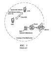
- As regards D2D communications, a known approach is shown in
Figure 1 . - As shown in
Figure 1 , both the user terminals, UE#1 and UE#2, are connected via a base station BS#1 connected via a local router to the internet. The connections to the base station are for control signalling whereas user traffic is exchanged directly via the D2D connection between the two user terminals. The control signalling indicates for example that an opportunistic direct connection may be set up under the control of the network ('operator governed'). - The reader is now referred to the appended independent claims. Some preferred features are laid out in the dependent claims.
- An example of the present invention is a method of data transmission between a first user terminal and a second user terminal in a cellular telecommunications network. The network comprises small cell base stations providing respective small cells. The method comprises: the network detecting a call set up request from the first user terminal in respect of the second terminal, the network determining that the first and second user terminals are in the same or neighbouring small cells, and
the network instructing at least one of the first and second terminals to set up a direct device -to-device (D2D) connection between the first and second user terminals. - Preferred embodiments have advantages over known approaches in which user data is sent via a small cell base station using LIPA or SIPTO or via the operator's IP core network.
- Preferred embodiments have an advantage that in consequence of the network tracking which cell user terminals are in, energy intensive and uneconomical discovery procedures such as broadcasting or probing are avoided.
- Preferred embodiments provide that less data is passed via the backhaul to operator's IP core network, and by using D2D links, data is passed through fewer nodes, so speed and reliability are improved. Using the direct device-to-device (D2D) connections enable the cellular network to offload traffic to D2D connections, and so increase spectral usage efficiency. Specifically, as cell base station load is reduced, both intracell interference and intercell interference may be reduced. This is because D2D connections involve lower signal powers and data not passing via the cellular network. In consequence, the spectral efficiency of neighbouring cells may also increased.
- Preferred embodiments may be considered as providing operator-governed opportunistic direct device-to-device communications between mobile user terminals, with the support of the small cell telecommunications network.
- Preferred embodiments allow automatic determination that user terminals are in the same or neighbouring cells so are suitable for direct D2D connection. In some embodiments, a request for D2D connection may be made by a user of a user terminal.
- The user data offload that occurs in preferred embodiments enable networks to support additional services, for example to user terminals having high data rate requirements. Due to the D2D connections, local network equipments, for example small cell base stations, may be offloaded of their data traffic to a significant extent. In some embodiments the associated control signalling goes into an operator's IP core network in the telecommunications network, but not the user data which is passed by direct D2D connection.
- In preferred embodiments, a direct D2D connection becoming weaker may cause further user data traffic between the two users to be shifted into the network for example over a LIPA connection. (A LIPA connection is via a shared base station, so the data does not pass via the operator's IP core network which is further in the telecommunications network.)
- In some preferred embodiments the small cell base stations are, for example, LTE HeNodeB and/or UMTS/3G Home NB.
- The present invention also relates to a corresponding telecommunications network node, and to a corresponding telecommunications network.
- Embodiments of the present invention will now be described by way of example and with reference to the drawings, in which:
-
Figure 1 is a diagram illustrating a network including a known network-controlled opportunistic D2D connection (PRIOR ART), -
Figure 2 is a diagram illustrating a network including a known conventional network-controlled connection in which the base station is a small cell base station (LTE HeNB) (PRIOR ART), -
Figure 3 is a diagram illustrating a network according to a first embodiment of the present invention, the network including a small cell base station of LTE HeNB type, within which there is a network-controlled opportunistic D2D connection, -
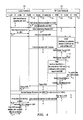
Figure 4 is a message sequence diagram illustrating example messaging for D2D connection setup between two user terminals in the network shown inFigure 3 , -
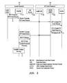
Figure 5 is a message sequence diagram illustrating example messaging in Network Address Translation in the network shown inFigure 2 , and -
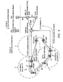
Figure 6 is a diagram illustrating a network according to a second embodiment of the present invention, the network including small cell base stations of LTE HeNB type each providing a cell and in which there is a network-controlled opportunistic D2D connection between two user terminals in different cells. - We first describe two known examples, then turn to describing example embodiments in detail.
- According to a first known approach, in a network involving small cell base stations of Long Term Evolution (LTE) Home evolved NodeB (HeNB) or Universal Mobile Telecommunications System (UMTS) Home NodeB (HNB) type, when the two user terminals are communicating with each other, data is conventionally transmitted via the small cell base station a local router and the operator's core network. However, it is known that the core network may be avoided, to some extent, in a second known approach shown in
Figure 2 . - As shown in
Figure 2 , in a network, opportunistic connections are supported in a small cell of LTE HeNodeB type, where LTE denotes Long Term Evolution and HeNodeB denotes a home base station. For simplicity,Figure 2 shows a single HeNodeB and two user terminals. A Long Term Evolution (LTE) Home evolved NodeB (HeNB) is sometimes denoted a 3G HeNB. - As shown in
Figure 2 , a Home Public Land Mobile Network (HPLMN) includes a Home Subscriber Server (HSS) and a Closed Subscriber Group list server (CSG). As shown inFigure 2 , a Visited Public Land Mobile Network (VPLAN) consists of a local network equipment and an Internet Protocol (IP) network. The local network equipment consists of the small cell base station (HeNodeB) and a local router. The small cell base station is connected via the local router to the IP core network. The IP core network includes a small cell gateway (HeNodeB-GW), a serving gateway (S-GW) and a Mobility Management Entity (MME), and Internet Service Provider (ISP) router. The local router is connected to the ISP router, and uses IP addresses, for access to the broader internet. - The small cell base station in this example is an LTE Home eNodeB, sometimes referred to as a HeNodeB. The small cell base station is for connection of suitable Third Generation Partnership Project (3GPP) user terminals over an LTE wireless interface to a mobile operator's IP core network using the broadband IP backhaul provided by the local router. In an alternative embodiment, the air interface may be a EUTRAN air interface.
- The small cell gateway, which is located at the premises of the network operator, enables the small cell base station to gain access to the network operator's IP core network. The small cell gateway is an aggregator that concentrates small call traffic received over an S1 interface providing an S1-MME interface to the MME and an S1-U interface towards the serving gateway.
- The Mobility Management Entity (MME) controls establishment of user plane tunnels and establishes user plane bearers between the small cell base station and the small cell gateway. The MME is connected via an S6a interface to the Home Subscriber Server (HSS) and is connected via an S11 interface to the serving gateway.
- The ISP router allows data packets to be routed directly to the internet without going via the operator's IP core network.
- As shown in
Figure 2 , the userterminal UE# 1 wishes to communicate with the second userterminal UE# 2, and both user terminals are in the same small cell. The two user terminals are connected to the cellular network via the small cell base station (HeNodeB). The communications between the two terminals basically go via the small cell base station the local router and the IP core network. - Local IP access (LIPA) is a known mechanism whereby an IP capable user terminal may communicate with that another IP capable device directly via a small cell base station, without going further within the mobile operator's IP core network. The IP capable user terminal is connected via the small cell base station to the IP capable device within in a residential IP network within a home or office. This may be considered effectively as an IP Traffic offload from the perspective of the operator's s IP core network.
- Another known mechanism is Selected IP Traffic Offload (SIPTO) which allows a small cell base station to provide access for a user terminal connected via the small cell base station to an IP network, for example via the local router and ISP router to the Internet, instead of via the operator's IP core network. LIPA and SIPTO links are both shown in
Figure 2 . - LIPA and SIPTO are known, for example, from Third Generation Partnership Project (3GPP)
Release 10 standards, for example TR23.829 "Local IP Access and Selected IP traffic Offload (LIPA-SIPTO)". - From considering the known system described with reference to
Figure 2 above, the inventor realised that using LIPA and SIPTO enabled some traffic to not need to go via the operator's IP core network (in other words' be "offloaded" from that IP core network). However in theFigure 2 approach, that traffic would pass via the local network namely the small cell base station and local router. - The inventor also realised that there is high energy consumption and signalling overheads on user terminals in the known systems during the procedures for discovery that two user terminals are near each other.
- The inventor also realised that when two mobile devices are relatively close together it is appropriate to have a direct device-to-device (D2D) link between the user terminals. The setup of this link is supported by the cellular network ('infrastructure supported') and is opportunistic in that such links are set up as and when appropriate. User data is transmitted via the D2D link.
- We now turn to describing example embodiments.
- As shown in
Figure 3 , in a network opportunistic D2D connections are supported in a small cell of LTE HeNodeB type, where LTE denotes Long Term Evolution and HeNodeB denotes a home base station. For simplicity,Figure 3 shows a single HeNodeB and two user terminals. - As shown in
Figure 3 , a Home Public Land Mobile Network (HPLMN) 2 includes a Home Subscriber Server (HSS) 4 and a Closed Subscriber Group list server (CSG) 6. As shown inFigure 3 , a Visited Public Land Mobile Network (VPLAN) 8 consists of alocal network equipment 10 and an Internet Protocol (IP)network 12. Thelocal network equipment 10 consists of the small cell base station (HeNodeB) 14 and alocal router 16. The smallcell base station 14 is connected via thelocal router 16 to theIP core network 12. TheIP core network 12 includes a small cell gateway (HeNB-GW) 18, a serving gateway (S-GW) 20, a Mobility Management Entity (MME) 22, and Internet Service Provider (ISP)router 24. Thelocal router 16 is connected to theISP router 24, and uses IP addresses, for access to the broader internet. - The small
cell base station 14 in this example is an LTE Home eNodeB, sometimes referred to as a HeNodeB or HeNB. The small cell base station is for connection of suitable Third Generation Partnership Project (3GPP) userterminals UE# 1,UE# 2 over an LTE wireless interface, namely thelocal network equipment 10, to the mobile operator'sIP core network 12 using thebroadband IP backhaul 26 provided by thelocal router 16. In an alternative embodiment (not shown), the wireless interface may be a EUTRAN air interface. - The
small cell gateway 18, which is located at the premises of the network operator, enables the smallcell base station 14 to gain access to the network operator'sIP core network 12. Thesmall cell gateway 18 is an aggregator that concentrates small call traffic received over an S1 interface providing an S1-MME interface to theMME 22 and an S1-U interface towards the servinggateway 20. - The Mobility Management Entity (MME) 22 controls establishment of user plane tunnels and establishes user plane bearers between the small cell base station and the small cell gateway. The
MME 22 is connected via an S6a interface to the Home Subscriber Server (HSS) 4 and is connected via an S11 interface to the servinggateway 20. - The
ISP router 24 allows data packets to be routed directly to the internet (not shown) without going via the operator'sIP core network 12. - As shown in
Figure 3 , the userterminal UE# 1 wishes to communicate with the second userterminal UE# 2, and both user terminals are in the same small cell provided by the smallcell base station 14. Accordingly an infrastructure supported, opportunistic direct D2D link is used as described in more detail as follows. - The user terminals are both attached to the infrastructure, namely the small
cell base station 14, for control signalling, for example indicating the suitability of an opportunistic D2D link. The control signalling passes via the smallcell base station 14 thelocal router 16 and theIP core network 12. - If the two user terminals are in the same small cell or in neighbouring small cells then a direct D2D link is likely to be worthwhile. A determination is made whether the two user terminals are in the same or neighbouring small cells. Specifically the
MME 22 knows which user terminals are in which small cells. In the example shown inFigure 3 , theMME 22 recognises thatUE# 2 is in the same small cell asUE# 1. - Having discovered that the
UE# 2 is in the same small cell (or a neighbouring small cell) asUE# 1, aD2D link 28 is set up and user traffic is exchanged directly between the two userterminals UE# 1,UE# 2 via theD2D link 28 as shown inFigure 3 . - In this example, if the D2D link becomes poor, in other words below a given quality threshold, data traffic is displaced onto the LIPA connection so as to pass via the small
cell base station 14, without going via the operator's IP core network. - Furthermore, in this example, other data traffic, for example between the terminals and other users elsewhere is passed via the
ISP router 24 to the internet (not shown) directly without going via the operator'sIP core network 12. - An example of how the D2D link is set up will now be described with reference to
Figure 4 . - As shown in
Figure 4 ,UE# 1 initiates (step a) a UE triggered service request with the smallcell base station 14. A standard service request procedure as specified in 3GPP Technical Specification 23.401 (version11.3.0) is then undertaken as shown in steps a to j. From the first uplink data provided (step f) the S-GW 20 identifies (step g) that the destination address ofUE# 2 is in the same cell asUE# 1 so communicates (steps i,j) this information to theMME 22. The MME additionally verifies (step k) that both of theUE# 1 andUE# 2 endpoints support direct D2D communication. - Following the above and some subsequent notification and paging steps (steps m to p) a service request procedure (step q) is undertaken for
UE# 2, essentially as done for UE#1 (and described with reference to steps a to j above), although this second service request procedure is network triggered. This service request procedure (step q) is also in line with 3GPP Technical Specification 23.401 (version11.3.0). - The S-
GW 20 then sends (step r) a stop paging message to theMME 22 which then sends (step s) a message to the small cell base station enabling the direct D2D connection betweenUE# 1 andUE# 2. The small cell base station then instructs (step t)UE# 1 in setting up the connection and instructs (step u)UE# 2 in setting up the connection. The direct D2D connection is then established (step v). - In this example the network automatically sets up D2D connections as above when appropriate, in other words when a call set up request is made form a user terminal to another user terminal that is determined as being sufficiently close.
- In an alternative but similar embodiment(not shown), one user selects the direct D2D service, for example a user controls his user
terminal UE# 1, when he sees the user ofUE# 2, nearby to initiate the network to determine that the two user terminals are nearby and if appropriate set up a D2D connection. This could be for example, between children in a school yard or work colleagues in an office. The network then determines whether a direct D2D connection toUE# 2 is appropriate upon a call set up request fromUE# 1 in respect ofUE# 2 being detected by the network. - Returning to the example shown in
Figure 3 (andFigure 4 ), Local IP access (LIPA) is a mechanism whereby an IP capable user terminal may communicate with that another IP capable device directly via a small cell base station, without going further within the mobile operator's IP core network. The IP capable user terminal is connected via the small cell base station to the IP capable device within in a residential IP network within a home or office. This may be considered effectively as an IP Traffic offload from the perspective of the operator's IP core network. Signalling still passes via the operator's IP core network. - Another mechanism is Selected IP Traffic Offload (SIPTO) which allows a small cell base station to provide access for a user terminal connected via the small cell base station to an IP network, for example via the local router and ISP router to the Internet, instead of via the operator's IP core network. LIPA and SIPTO links are both shown in
Figure 3 . - LIPA and SIPTO are known, for example, from Third Generation Partnership Project (3GPP)
Release 10 standards. - In the network shown in
Figure 3 , both LIPA and SIPTO are used. One approach used here, from the range of approaches defined for LIPA-SIPTO, is for Local IP access (LIPA) and Selected IP Traffic Offload (SIPTO) to occur at the HeNodeB by Network Address Translation. This is illustrated inFigure 5 . - For completeness, how this Network Address Translation is done is now described with reference to
Figure 5. Figure 5 includes a network element of a Gateway GPRS support node (GGSN) which is in the operator'sIP core network 12 between theMME 22 and theHPLMN 2 shown inFigure 3 . - Referring to
Figure 5 , each of the user terminals has a single Access Point Name (APN). When requesting a PDP Context, the user terminal sends (indicated by a inFigure 4 ) a 'create PDP Context request' message towards the GGSN which responds (indicated by b inFigure 5 ) with a 'create PDP Context response' message that gives details of the activated PDP context including an IP address allocated to the user terminal (or an indication of request failure with a reason for failure). The smallcell base station 14 reads this message and so obtains the IP address of the user terminal. The smallcell base station 14 then requests a local IP subnet address from a Dynamic Host Configuration Protocol (DHCP) server, namely theISP router 24 in this example, and maps this subnet address to the IP address allocated to the user terminal by the GGSN. This is indicated inFigure 5 by (c). - The small
cell base station 14 then inspects all data packets originating from or destined for the user terminals to see the source and destination IP addresses. Deep Packet Inspection (DPI) of the IP headers of data packets is used to do this, to determine which path is to be taken (via the operator'sIP core network 12 or via thelocal router 16. The smallcell base station 14 modifies the source or destination IP address, as appropriate, so as to enable proper routing of the data either via a GTP tunnel to the operator'sIP core network 12 or to thelocal router 16. - It may be noted that user terminals may support multiple Packet Data Network (PDN) connections so can use both LIPA and non-LIPA connections. Also for user terminals the usual path to a GGSN is unchanged so handovers are not affected.
- Another situation is where the user terminals that wish to communicate with each other are in neighbouring small cells.
- As shown in
Figure 6 , a network similar to that shown inFigure 3 is provided. InFigure 6 , three neighbouringsmall cells 3 are shown but just two of the base stations 14' and just two user terminals UE#1' , UE#2' are shown for simplicity. - A VPLMN 8' and HPLMN 2' are provided basically as described in respect of
Figure 3 above. The VPLMN contains local network equipments 10' each consisting of a small cell base station 14' and associated local router 16'. In this example, multiple small cell base stations in contiguous cells share a common operator IP core network 12'. In the example shown inFigure 6 , only one operator IP core network 12' applies. In some other similar embodiments, more operator IP core networks may be involved, each supporting one or more small cell base stations. - The two user terminals wish to communicate with each other.
- A determination is made whether the two user terminals are sufficiently close together for a direct D2D link to be worthwhile. More specifically, the determination is whether the two user terminals are in the same or neighbouring small cells. Specifically the MME 22' has information of which user terminals are in which small cells. In the example shown in
Figure 6 , the MME 22' recognises thatUE# 2 is in a neighbouring small cell toUE# 1, and both are connected by a respective small cell base station to the IP core network 12', the two small cell base stations 14' being neighbours. - Usually, traffic is passed from a user terminal via a small cell base station 14' and local IP router 16' to the IP core network 12' or to an ISP router 24' using SIPTO as described above. Traffic may also pass between the two ISP routers 24' shown in
Figure 5 . - However, on discovery that the two user terminals are connected to neighbouring small cell base stations 14' a D2D link 28'is set up between the two user terminals and user traffic is exchanged directly between the two user
terminals UE# 1,UE# 2 via the D2D link 28'. Then only the control signalling, for example indicating that a D2D link is suitable, is passed via the operator's IP core network 12'. - In consequence, the IP core network is offloaded as data traffic is passed via the D2D link. This approach may be considered an operator-governed opportunistic direct D2D communication between user terminals in neighbouring small cells.
- The present invention may be embodied in other specific forms without departing from its essential characteristics. For example the examples described above with reference to
Figure 3 to 6 relate to LTE small cell base stations (HeNodeB). For example, other embodiments (not shown), some similar, relate to UMTS small cell base stations, sometimes known as 3G Home NB. A Universal Mobile Telecommunications System (UMTS) Home NodeB (HNB) may be known as a 3G HNB. - The described embodiments are to be considered in all respects only as illustrative and not restrictive. The scope of the invention is, therefore, indicated by the appended claims rather than by the foregoing description. All changes that come within the meaning and range of equivalency of the claims are to be embraced within their scope.
- A person skilled in the art would readily recognize that steps of various above-described methods can be performed by programmed computers. Some embodiments relate to program storage devices, e.g., digital data storage media, which are machine or computer readable and encode machine-executable or computer-executable programs of instructions, wherein said instructions perform some or all of the steps of said above-described methods. The program storage devices may be, e.g., digital memories, magnetic storage media such as a magnetic disks and magnetic tapes, hard drives, or optically readable digital data storage media. Some embodiments involve computers programmed to perform said steps of the above-described methods.
Claims (16)
- A method of data transmission between a first user terminal and a second user terminal in a cellular telecommunications network comprising small cell base stations providing respective small cells, the method comprising:the network detecting a call set up request from the first user terminal in respect of the second user terminal;the network determining that the first and second user terminals are in the same or neighbouring small cells; andthe network instructing at least one of the first and second terminals to set up a direct device -to-device (D2D) connection between the first and second user terminals.
- A method according to claim 1, in which said determining that the first and second user terminals are in the same or neighbouring small cells is by inspecting a record of in which cells user terminals are located.
- A method according to claim 1 or claim 2, in which the user data is sent via the D2D connection, and control signalling is sent via at least one of the small cell base stations.
- A method according to claim 3, in which the two user terminals are in the same cell, and control signalling is sent via the small cell base station providing that cell using a Local IP Access, LIPA.
- A method according to claim 3 or claim 4, in which upon the signal quality of the D2D connection going below a given threshold, further user data is instead sent via the small cell base station providing that cell using a Local IP Access, LIPA.
- A method according to claim 3, in which the two user terminals are in neighbouring cells, and control signalling is sent via the two small cell base stations using Selected Internet Protocol Traffic offload, SIPTO.
- A method according to claim 3 or claim 6, in which upon the signal quality of the D2D connection going below a given threshold, further user data is instead sent via the two small cell base stations using Selected Internet Protocol Traffic offload, SIPTO.
- A method according to any preceding claim in which said determining by the network that the first and second user terminals are in the same or neighbouring small cells is triggered by a request for direct D2D connection from the first user terminal.
- A telecommunications network node configured to:detect a call set up request from a first user terminal to a second user terminal,identify that the first and second user terminals are in the same or neighbouring small cells, andsend an instruction towards at least one of the user terminals to set up a direct device -to-device (D2D) connection between the first and second user terminals.
- A telecommunications network node according to claim 9, in which the instruction is for user data to be sent via the D2D connection.
- A telecommunications network node according to claim 9 or claim 10, configured to maintain a record of in which cell each user terminal connected to the network is located, for use in identifying that the first and second user terminals are in the same or neighbouring small cells,
- A telecommunications network node according to any of claims 9 to 11, which is a Mobility Management Entity, MME.
- A cellular telecommunications network comprising small cell base stations providing respective small cells, the network being configured to detect a call set up request from the first user terminal in respect of the second terminal, to determine that the first and second user terminals are in the same or neighbouring small cells, and to instruct at least one of the first and second terminals to set up a direct device -to-device (D2D) connection between the first and second user terminals.
- A cellular telecommunications network according to claim 13, in which, in use, the user data is sent via the D2D connection, and control signalling is sent via at least one of the small cell base stations.
- A cellular telecommunications network according to claim 14, in which, in use, the two user terminals are in the same cell, and control signalling is sent via the small cell base station providing that cell using a Local IP Access, LIPA.
- A cellular telecommunications network according to claim 14, in which, in use, the two user terminals are in neighbouring cells, and control signalling is sent via the two small cell base stations and the Internet using Selected Internet Protocol Traffic offload, SIPTO.
Priority Applications (1)
| Application Number | Priority Date | Filing Date | Title |
|---|---|---|---|
| EP12290432.9A EP2744293B1 (en) | 2012-12-12 | 2012-12-12 | A telecommunications network, a node, and a method of data transmission |
Applications Claiming Priority (1)
| Application Number | Priority Date | Filing Date | Title |
|---|---|---|---|
| EP12290432.9A EP2744293B1 (en) | 2012-12-12 | 2012-12-12 | A telecommunications network, a node, and a method of data transmission |
Publications (2)
| Publication Number | Publication Date |
|---|---|
| EP2744293A1 true EP2744293A1 (en) | 2014-06-18 |
| EP2744293B1 EP2744293B1 (en) | 2016-03-02 |
Family
ID=47469801
Family Applications (1)
| Application Number | Title | Priority Date | Filing Date |
|---|---|---|---|
| EP12290432.9A Active EP2744293B1 (en) | 2012-12-12 | 2012-12-12 | A telecommunications network, a node, and a method of data transmission |
Country Status (1)
| Country | Link |
|---|---|
| EP (1) | EP2744293B1 (en) |
Cited By (3)
| Publication number | Priority date | Publication date | Assignee | Title |
|---|---|---|---|---|
| CN104394569A (en) * | 2014-11-14 | 2015-03-04 | 西安交通大学 | Angle and interference control based multicast routing establishment method in wireless D2D (Device to Device) network |
| KR20190007405A (en) * | 2018-12-28 | 2019-01-22 | 주식회사 온페이스 | D-to-D system using 5G small cell, and the method therefor |
| WO2023280088A1 (en) * | 2021-07-09 | 2023-01-12 | 展讯半导体(南京)有限公司 | Data routing method and apparatus |
Citations (7)
| Publication number | Priority date | Publication date | Assignee | Title |
|---|---|---|---|---|
| TR23829A (en) | 1988-06-25 | 1990-09-25 | Henkel Kgaa | ALL PROPERTIES TO REMOVE SHEET SILICATES WITH FLUIDABILITY |
| WO2001062026A1 (en) * | 2000-02-17 | 2001-08-23 | Nokia Corporation | Handling connections in a mobile network |
| US20060193292A1 (en) * | 2005-02-28 | 2006-08-31 | Microsoft Corporation | Measurement based mechanism to enable two wireless devices to directly communicate with each other to support traffic prioritization |
| US20100169498A1 (en) * | 2008-12-30 | 2010-07-01 | Qualcomm Incorporated | Centralized control of peer-to-peer communication |
| US20100220642A1 (en) * | 2009-02-27 | 2010-09-02 | Charles Abraham | Method and system for peer-to-peer cellular communications |
| US20100260101A1 (en) * | 2009-04-08 | 2010-10-14 | Qualcomm Incorporated | Route optimization for directly connected peers |
| US20110244899A1 (en) * | 2010-03-31 | 2011-10-06 | Qualcomm Incorporated | Methods and apparatus for determining a communications mode and/or using a determined communications mode |
-
2012
- 2012-12-12 EP EP12290432.9A patent/EP2744293B1/en active Active
Patent Citations (7)
| Publication number | Priority date | Publication date | Assignee | Title |
|---|---|---|---|---|
| TR23829A (en) | 1988-06-25 | 1990-09-25 | Henkel Kgaa | ALL PROPERTIES TO REMOVE SHEET SILICATES WITH FLUIDABILITY |
| WO2001062026A1 (en) * | 2000-02-17 | 2001-08-23 | Nokia Corporation | Handling connections in a mobile network |
| US20060193292A1 (en) * | 2005-02-28 | 2006-08-31 | Microsoft Corporation | Measurement based mechanism to enable two wireless devices to directly communicate with each other to support traffic prioritization |
| US20100169498A1 (en) * | 2008-12-30 | 2010-07-01 | Qualcomm Incorporated | Centralized control of peer-to-peer communication |
| US20100220642A1 (en) * | 2009-02-27 | 2010-09-02 | Charles Abraham | Method and system for peer-to-peer cellular communications |
| US20100260101A1 (en) * | 2009-04-08 | 2010-10-14 | Qualcomm Incorporated | Route optimization for directly connected peers |
| US20110244899A1 (en) * | 2010-03-31 | 2011-10-06 | Qualcomm Incorporated | Methods and apparatus for determining a communications mode and/or using a determined communications mode |
Non-Patent Citations (1)
| Title |
|---|
| ALCATEL-LUCENT ET AL: "Restructuration of TR 23.829", 3GPP DRAFT; S2-101719 WAS 1449_23829 RESTRUCTURING_R0, 3RD GENERATION PARTNERSHIP PROJECT (3GPP), MOBILE COMPETENCE CENTRE ; 650, ROUTE DES LUCIOLES ; F-06921 SOPHIA-ANTIPOLIS CEDEX ; FRANCE, vol. SA WG2, no. San Francisco, USA; 20100222, 25 February 2010 (2010-02-25), XP050434102 * |
Cited By (6)
| Publication number | Priority date | Publication date | Assignee | Title |
|---|---|---|---|---|
| CN104394569A (en) * | 2014-11-14 | 2015-03-04 | 西安交通大学 | Angle and interference control based multicast routing establishment method in wireless D2D (Device to Device) network |
| CN104394569B (en) * | 2014-11-14 | 2017-10-20 | 西安交通大学 | The method that QoS routing is set up based on angle and interference control in wireless D2D networks |
| KR20190007405A (en) * | 2018-12-28 | 2019-01-22 | 주식회사 온페이스 | D-to-D system using 5G small cell, and the method therefor |
| KR102011666B1 (en) | 2018-12-28 | 2019-08-19 | 주식회사 온페이스 | D-to-D system using 5G small cell, and the method therefor |
| WO2020138790A3 (en) * | 2018-12-28 | 2020-08-20 | 주식회사 온페이스 | D-to-d system using 5g small cell and method thereof |
| WO2023280088A1 (en) * | 2021-07-09 | 2023-01-12 | 展讯半导体(南京)有限公司 | Data routing method and apparatus |
Also Published As
| Publication number | Publication date |
|---|---|
| EP2744293B1 (en) | 2016-03-02 |
Similar Documents
| Publication | Publication Date | Title |
|---|---|---|
| US11134427B2 (en) | Terminal, base station, cell access method, and data transmission method for reconfiguring a wireless connection to communicate with a secondary cell | |
| TWI821728B (en) | Method and device for enabling non-3gpp offload in 3gpp | |
| JP6105758B2 (en) | Method and apparatus for establishing a cellular session in a wireless communication system | |
| US9241354B2 (en) | Method and apparatus for initiating X2 interface setup in wireless communication system | |
| CN110493887B (en) | Method and apparatus for information transmission | |
| US11129054B2 (en) | Methods, systems and devices for supporting local breakout in small cell architecture | |
| CN107113601B (en) | Method and apparatus for supporting independent local gateway services for dual connectivity in a wireless communication system | |
| WO2015005626A1 (en) | Method for controlling relay on basis of proximity service and device therefor | |
| US20120003980A1 (en) | Method and apparatus for supporting local breakout in wireless communication network including femtocells | |
| CN106576397B (en) | Method and apparatus for supporting local gateway service for dual connectivity in wireless communication system | |
| KR20120000859A (en) | Wireless communication system and method of performing handover in the system | |
| US20180139691A1 (en) | Communication method, communication system, base station for mobile communication, and communication device for wireless lan | |
| US9736717B2 (en) | Access method, base station, access point and user equipment | |
| WO2015105383A1 (en) | Method and apparatus for obtaining information for 3gpp lte-wlan interworking in wireless communication system | |
| KR20150035143A (en) | Method for providing mobile telecommunication service, and apparatus therefor | |
| WO2015108364A1 (en) | Method and apparatus for obtaining radio access network sharing information in wireless communication system | |
| EP2744293B1 (en) | A telecommunications network, a node, and a method of data transmission | |
| US10321491B2 (en) | Method and apparatus for supporting local gateway service for dual connectivity in wireless communication system | |
| US20180199241A1 (en) | Method and apparatus for enhancing coordination of lte-wlan in wireless communication system | |
| WO2014129714A1 (en) | Method and apparatus for transmitting cell load information in wireless communication system | |
| WO2015133754A1 (en) | Method and apparatus for managing qos in wireless communication system | |
| KR101587416B1 (en) | method for obtaining IP addrss of mobile telecommunication terminal in LTE femtocell | |
| KR20200078448A (en) | Method for providing mobile telecommunication service, and apparatus therefor |
Legal Events
| Date | Code | Title | Description |
|---|---|---|---|
| PUAI | Public reference made under article 153(3) epc to a published international application that has entered the european phase |
Free format text: ORIGINAL CODE: 0009012 |
|
| 17P | Request for examination filed |
Effective date: 20121212 |
|
| AK | Designated contracting states |
Kind code of ref document: A1 Designated state(s): AL AT BE BG CH CY CZ DE DK EE ES FI FR GB GR HR HU IE IS IT LI LT LU LV MC MK MT NL NO PL PT RO RS SE SI SK SM TR |
|
| AX | Request for extension of the european patent |
Extension state: BA ME |
|
| RAP1 | Party data changed (applicant data changed or rights of an application transferred) |
Owner name: ALCATEL LUCENT |
|
| R17P | Request for examination filed (corrected) |
Effective date: 20141218 |
|
| RBV | Designated contracting states (corrected) |
Designated state(s): AL AT BE BG CH CY CZ DE DK EE ES FI FR GB GR HR HU IE IS IT LI LT LU LV MC MK MT NL NO PL PT RO RS SE SI SK SM TR |
|
| GRAP | Despatch of communication of intention to grant a patent |
Free format text: ORIGINAL CODE: EPIDOSNIGR1 |
|
| INTG | Intention to grant announced |
Effective date: 20150714 |
|
| GRAS | Grant fee paid |
Free format text: ORIGINAL CODE: EPIDOSNIGR3 |
|
| GRAA | (expected) grant |
Free format text: ORIGINAL CODE: 0009210 |
|
| AK | Designated contracting states |
Kind code of ref document: B1 Designated state(s): AL AT BE BG CH CY CZ DE DK EE ES FI FR GB GR HR HU IE IS IT LI LT LU LV MC MK MT NL NO PL PT RO RS SE SI SK SM TR |
|
| REG | Reference to a national code |
Ref country code: GB Ref legal event code: FG4D |
|
| REG | Reference to a national code |
Ref country code: AT Ref legal event code: REF Ref document number: 778744 Country of ref document: AT Kind code of ref document: T Effective date: 20160315 Ref country code: CH Ref legal event code: EP |
|
| REG | Reference to a national code |
Ref country code: IE Ref legal event code: FG4D |
|
| REG | Reference to a national code |
Ref country code: DE Ref legal event code: R096 Ref document number: 602012015161 Country of ref document: DE |
|
| REG | Reference to a national code |
Ref country code: NL Ref legal event code: MP Effective date: 20160302 |
|
| REG | Reference to a national code |
Ref country code: LT Ref legal event code: MG4D |
|
| REG | Reference to a national code |
Ref country code: AT Ref legal event code: MK05 Ref document number: 778744 Country of ref document: AT Kind code of ref document: T Effective date: 20160302 |
|
| PG25 | Lapsed in a contracting state [announced via postgrant information from national office to epo] |
Ref country code: HR Free format text: LAPSE BECAUSE OF FAILURE TO SUBMIT A TRANSLATION OF THE DESCRIPTION OR TO PAY THE FEE WITHIN THE PRESCRIBED TIME-LIMIT Effective date: 20160302 Ref country code: GR Free format text: LAPSE BECAUSE OF FAILURE TO SUBMIT A TRANSLATION OF THE DESCRIPTION OR TO PAY THE FEE WITHIN THE PRESCRIBED TIME-LIMIT Effective date: 20160603 Ref country code: FI Free format text: LAPSE BECAUSE OF FAILURE TO SUBMIT A TRANSLATION OF THE DESCRIPTION OR TO PAY THE FEE WITHIN THE PRESCRIBED TIME-LIMIT Effective date: 20160302 Ref country code: ES Free format text: LAPSE BECAUSE OF FAILURE TO SUBMIT A TRANSLATION OF THE DESCRIPTION OR TO PAY THE FEE WITHIN THE PRESCRIBED TIME-LIMIT Effective date: 20160302 Ref country code: NO Free format text: LAPSE BECAUSE OF FAILURE TO SUBMIT A TRANSLATION OF THE DESCRIPTION OR TO PAY THE FEE WITHIN THE PRESCRIBED TIME-LIMIT Effective date: 20160602 |
|
| PG25 | Lapsed in a contracting state [announced via postgrant information from national office to epo] |
Ref country code: LT Free format text: LAPSE BECAUSE OF FAILURE TO SUBMIT A TRANSLATION OF THE DESCRIPTION OR TO PAY THE FEE WITHIN THE PRESCRIBED TIME-LIMIT Effective date: 20160302 Ref country code: RS Free format text: LAPSE BECAUSE OF FAILURE TO SUBMIT A TRANSLATION OF THE DESCRIPTION OR TO PAY THE FEE WITHIN THE PRESCRIBED TIME-LIMIT Effective date: 20160302 Ref country code: AT Free format text: LAPSE BECAUSE OF FAILURE TO SUBMIT A TRANSLATION OF THE DESCRIPTION OR TO PAY THE FEE WITHIN THE PRESCRIBED TIME-LIMIT Effective date: 20160302 Ref country code: SE Free format text: LAPSE BECAUSE OF FAILURE TO SUBMIT A TRANSLATION OF THE DESCRIPTION OR TO PAY THE FEE WITHIN THE PRESCRIBED TIME-LIMIT Effective date: 20160302 Ref country code: NL Free format text: LAPSE BECAUSE OF FAILURE TO SUBMIT A TRANSLATION OF THE DESCRIPTION OR TO PAY THE FEE WITHIN THE PRESCRIBED TIME-LIMIT Effective date: 20160302 Ref country code: PL Free format text: LAPSE BECAUSE OF FAILURE TO SUBMIT A TRANSLATION OF THE DESCRIPTION OR TO PAY THE FEE WITHIN THE PRESCRIBED TIME-LIMIT Effective date: 20160302 Ref country code: LV Free format text: LAPSE BECAUSE OF FAILURE TO SUBMIT A TRANSLATION OF THE DESCRIPTION OR TO PAY THE FEE WITHIN THE PRESCRIBED TIME-LIMIT Effective date: 20160302 |
|
| PG25 | Lapsed in a contracting state [announced via postgrant information from national office to epo] |
Ref country code: IS Free format text: LAPSE BECAUSE OF FAILURE TO SUBMIT A TRANSLATION OF THE DESCRIPTION OR TO PAY THE FEE WITHIN THE PRESCRIBED TIME-LIMIT Effective date: 20160702 Ref country code: EE Free format text: LAPSE BECAUSE OF FAILURE TO SUBMIT A TRANSLATION OF THE DESCRIPTION OR TO PAY THE FEE WITHIN THE PRESCRIBED TIME-LIMIT Effective date: 20160302 |
|
| PG25 | Lapsed in a contracting state [announced via postgrant information from national office to epo] |
Ref country code: PT Free format text: LAPSE BECAUSE OF FAILURE TO SUBMIT A TRANSLATION OF THE DESCRIPTION OR TO PAY THE FEE WITHIN THE PRESCRIBED TIME-LIMIT Effective date: 20160704 Ref country code: RO Free format text: LAPSE BECAUSE OF FAILURE TO SUBMIT A TRANSLATION OF THE DESCRIPTION OR TO PAY THE FEE WITHIN THE PRESCRIBED TIME-LIMIT Effective date: 20160302 Ref country code: SM Free format text: LAPSE BECAUSE OF FAILURE TO SUBMIT A TRANSLATION OF THE DESCRIPTION OR TO PAY THE FEE WITHIN THE PRESCRIBED TIME-LIMIT Effective date: 20160302 Ref country code: SK Free format text: LAPSE BECAUSE OF FAILURE TO SUBMIT A TRANSLATION OF THE DESCRIPTION OR TO PAY THE FEE WITHIN THE PRESCRIBED TIME-LIMIT Effective date: 20160302 Ref country code: CZ Free format text: LAPSE BECAUSE OF FAILURE TO SUBMIT A TRANSLATION OF THE DESCRIPTION OR TO PAY THE FEE WITHIN THE PRESCRIBED TIME-LIMIT Effective date: 20160302 |
|
| REG | Reference to a national code |
Ref country code: DE Ref legal event code: R097 Ref document number: 602012015161 Country of ref document: DE |
|
| REG | Reference to a national code |
Ref country code: FR Ref legal event code: PLFP Year of fee payment: 5 |
|
| PG25 | Lapsed in a contracting state [announced via postgrant information from national office to epo] |
Ref country code: IT Free format text: LAPSE BECAUSE OF FAILURE TO SUBMIT A TRANSLATION OF THE DESCRIPTION OR TO PAY THE FEE WITHIN THE PRESCRIBED TIME-LIMIT Effective date: 20160302 Ref country code: BE Free format text: LAPSE BECAUSE OF FAILURE TO SUBMIT A TRANSLATION OF THE DESCRIPTION OR TO PAY THE FEE WITHIN THE PRESCRIBED TIME-LIMIT Effective date: 20160302 |
|
| PLBE | No opposition filed within time limit |
Free format text: ORIGINAL CODE: 0009261 |
|
| STAA | Information on the status of an ep patent application or granted ep patent |
Free format text: STATUS: NO OPPOSITION FILED WITHIN TIME LIMIT |
|
| PG25 | Lapsed in a contracting state [announced via postgrant information from national office to epo] |
Ref country code: DK Free format text: LAPSE BECAUSE OF FAILURE TO SUBMIT A TRANSLATION OF THE DESCRIPTION OR TO PAY THE FEE WITHIN THE PRESCRIBED TIME-LIMIT Effective date: 20160302 |
|
| 26N | No opposition filed |
Effective date: 20161205 |
|
| PG25 | Lapsed in a contracting state [announced via postgrant information from national office to epo] |
Ref country code: SI Free format text: LAPSE BECAUSE OF FAILURE TO SUBMIT A TRANSLATION OF THE DESCRIPTION OR TO PAY THE FEE WITHIN THE PRESCRIBED TIME-LIMIT Effective date: 20160302 Ref country code: BG Free format text: LAPSE BECAUSE OF FAILURE TO SUBMIT A TRANSLATION OF THE DESCRIPTION OR TO PAY THE FEE WITHIN THE PRESCRIBED TIME-LIMIT Effective date: 20160602 |
|
| REG | Reference to a national code |
Ref country code: CH Ref legal event code: PL |
|
| PG25 | Lapsed in a contracting state [announced via postgrant information from national office to epo] |
Ref country code: MC Free format text: LAPSE BECAUSE OF FAILURE TO SUBMIT A TRANSLATION OF THE DESCRIPTION OR TO PAY THE FEE WITHIN THE PRESCRIBED TIME-LIMIT Effective date: 20160302 |
|
| REG | Reference to a national code |
Ref country code: IE Ref legal event code: MM4A |
|
| PG25 | Lapsed in a contracting state [announced via postgrant information from national office to epo] |
Ref country code: LU Free format text: LAPSE BECAUSE OF NON-PAYMENT OF DUE FEES Effective date: 20161212 Ref country code: LI Free format text: LAPSE BECAUSE OF NON-PAYMENT OF DUE FEES Effective date: 20161231 Ref country code: CH Free format text: LAPSE BECAUSE OF NON-PAYMENT OF DUE FEES Effective date: 20161231 |
|
| REG | Reference to a national code |
Ref country code: DE Ref legal event code: R079 Ref document number: 602012015161 Country of ref document: DE Free format text: PREVIOUS MAIN CLASS: H04W0076020000 Ipc: H04W0076100000 |
|
| PG25 | Lapsed in a contracting state [announced via postgrant information from national office to epo] |
Ref country code: IE Free format text: LAPSE BECAUSE OF NON-PAYMENT OF DUE FEES Effective date: 20161212 |
|
| REG | Reference to a national code |
Ref country code: FR Ref legal event code: PLFP Year of fee payment: 6 |
|
| PG25 | Lapsed in a contracting state [announced via postgrant information from national office to epo] |
Ref country code: HU Free format text: LAPSE BECAUSE OF FAILURE TO SUBMIT A TRANSLATION OF THE DESCRIPTION OR TO PAY THE FEE WITHIN THE PRESCRIBED TIME-LIMIT; INVALID AB INITIO Effective date: 20121212 |
|
| PG25 | Lapsed in a contracting state [announced via postgrant information from national office to epo] |
Ref country code: MK Free format text: LAPSE BECAUSE OF FAILURE TO SUBMIT A TRANSLATION OF THE DESCRIPTION OR TO PAY THE FEE WITHIN THE PRESCRIBED TIME-LIMIT Effective date: 20160302 Ref country code: CY Free format text: LAPSE BECAUSE OF FAILURE TO SUBMIT A TRANSLATION OF THE DESCRIPTION OR TO PAY THE FEE WITHIN THE PRESCRIBED TIME-LIMIT Effective date: 20160302 |
|
| PG25 | Lapsed in a contracting state [announced via postgrant information from national office to epo] |
Ref country code: MT Free format text: LAPSE BECAUSE OF NON-PAYMENT OF DUE FEES Effective date: 20161212 |
|
| PG25 | Lapsed in a contracting state [announced via postgrant information from national office to epo] |
Ref country code: AL Free format text: LAPSE BECAUSE OF FAILURE TO SUBMIT A TRANSLATION OF THE DESCRIPTION OR TO PAY THE FEE WITHIN THE PRESCRIBED TIME-LIMIT Effective date: 20160302 Ref country code: TR Free format text: LAPSE BECAUSE OF FAILURE TO SUBMIT A TRANSLATION OF THE DESCRIPTION OR TO PAY THE FEE WITHIN THE PRESCRIBED TIME-LIMIT Effective date: 20160302 |
|
| PGFP | Annual fee paid to national office [announced via postgrant information from national office to epo] |
Ref country code: DE Payment date: 20251104 Year of fee payment: 14 |
|
| PGFP | Annual fee paid to national office [announced via postgrant information from national office to epo] |
Ref country code: GB Payment date: 20251030 Year of fee payment: 14 |
|
| PGFP | Annual fee paid to national office [announced via postgrant information from national office to epo] |
Ref country code: FR Payment date: 20251110 Year of fee payment: 14 |