EP2744206A1 - Image projection device with microphone for proximity detection - Google Patents
Image projection device with microphone for proximity detection Download PDFInfo
- Publication number
- EP2744206A1 EP2744206A1 EP13190922.8A EP13190922A EP2744206A1 EP 2744206 A1 EP2744206 A1 EP 2744206A1 EP 13190922 A EP13190922 A EP 13190922A EP 2744206 A1 EP2744206 A1 EP 2744206A1
- Authority
- EP
- European Patent Office
- Prior art keywords
- image
- microphone
- displaying device
- image displaying
- area
- Prior art date
- Legal status (The legal status is an assumption and is not a legal conclusion. Google has not performed a legal analysis and makes no representation as to the accuracy of the status listed.)
- Withdrawn
Links
- 238000001514 detection method Methods 0.000 title description 9
- 230000001419 dependent effect Effects 0.000 claims 1
- 238000010586 diagram Methods 0.000 description 9
- 238000000034 method Methods 0.000 description 8
- 238000011156 evaluation Methods 0.000 description 3
- SKSZCWXNZIXXAY-UHFFFAOYSA-N isothiofulminic acid Chemical compound S[N+]#[C-] SKSZCWXNZIXXAY-UHFFFAOYSA-N 0.000 description 3
- 239000000463 material Substances 0.000 description 2
- 230000003287 optical effect Effects 0.000 description 2
- 230000009286 beneficial effect Effects 0.000 description 1
- 238000003384 imaging method Methods 0.000 description 1
- 230000001360 synchronised effect Effects 0.000 description 1
- 238000011144 upstream manufacturing Methods 0.000 description 1
Images




Classifications
-
- G—PHYSICS
- G03—PHOTOGRAPHY; CINEMATOGRAPHY; ANALOGOUS TECHNIQUES USING WAVES OTHER THAN OPTICAL WAVES; ELECTROGRAPHY; HOLOGRAPHY
- G03B—APPARATUS OR ARRANGEMENTS FOR TAKING PHOTOGRAPHS OR FOR PROJECTING OR VIEWING THEM; APPARATUS OR ARRANGEMENTS EMPLOYING ANALOGOUS TECHNIQUES USING WAVES OTHER THAN OPTICAL WAVES; ACCESSORIES THEREFOR
- G03B21/00—Projectors or projection-type viewers; Accessories therefor
- G03B21/14—Details
- G03B21/142—Adjusting of projection optics
-
- G—PHYSICS
- G03—PHOTOGRAPHY; CINEMATOGRAPHY; ANALOGOUS TECHNIQUES USING WAVES OTHER THAN OPTICAL WAVES; ELECTROGRAPHY; HOLOGRAPHY
- G03B—APPARATUS OR ARRANGEMENTS FOR TAKING PHOTOGRAPHS OR FOR PROJECTING OR VIEWING THEM; APPARATUS OR ARRANGEMENTS EMPLOYING ANALOGOUS TECHNIQUES USING WAVES OTHER THAN OPTICAL WAVES; ACCESSORIES THEREFOR
- G03B21/00—Projectors or projection-type viewers; Accessories therefor
- G03B21/14—Details
- G03B21/20—Lamp housings
- G03B21/2006—Lamp housings characterised by the light source
- G03B21/2033—LED or laser light sources
-
- G—PHYSICS
- G03—PHOTOGRAPHY; CINEMATOGRAPHY; ANALOGOUS TECHNIQUES USING WAVES OTHER THAN OPTICAL WAVES; ELECTROGRAPHY; HOLOGRAPHY
- G03B—APPARATUS OR ARRANGEMENTS FOR TAKING PHOTOGRAPHS OR FOR PROJECTING OR VIEWING THEM; APPARATUS OR ARRANGEMENTS EMPLOYING ANALOGOUS TECHNIQUES USING WAVES OTHER THAN OPTICAL WAVES; ACCESSORIES THEREFOR
- G03B21/00—Projectors or projection-type viewers; Accessories therefor
- G03B21/14—Details
- G03B21/20—Lamp housings
- G03B21/2053—Intensity control of illuminating light
-
- G—PHYSICS
- G03—PHOTOGRAPHY; CINEMATOGRAPHY; ANALOGOUS TECHNIQUES USING WAVES OTHER THAN OPTICAL WAVES; ELECTROGRAPHY; HOLOGRAPHY
- G03B—APPARATUS OR ARRANGEMENTS FOR TAKING PHOTOGRAPHS OR FOR PROJECTING OR VIEWING THEM; APPARATUS OR ARRANGEMENTS EMPLOYING ANALOGOUS TECHNIQUES USING WAVES OTHER THAN OPTICAL WAVES; ACCESSORIES THEREFOR
- G03B21/00—Projectors or projection-type viewers; Accessories therefor
- G03B21/14—Details
- G03B21/20—Lamp housings
- G03B21/2086—Security or safety means in lamp houses
-
- G—PHYSICS
- G03—PHOTOGRAPHY; CINEMATOGRAPHY; ANALOGOUS TECHNIQUES USING WAVES OTHER THAN OPTICAL WAVES; ELECTROGRAPHY; HOLOGRAPHY
- G03B—APPARATUS OR ARRANGEMENTS FOR TAKING PHOTOGRAPHS OR FOR PROJECTING OR VIEWING THEM; APPARATUS OR ARRANGEMENTS EMPLOYING ANALOGOUS TECHNIQUES USING WAVES OTHER THAN OPTICAL WAVES; ACCESSORIES THEREFOR
- G03B31/00—Associated working of cameras or projectors with sound-recording or sound-reproducing means
-
- H—ELECTRICITY
- H04—ELECTRIC COMMUNICATION TECHNIQUE
- H04N—PICTORIAL COMMUNICATION, e.g. TELEVISION
- H04N9/00—Details of colour television systems
- H04N9/12—Picture reproducers
- H04N9/31—Projection devices for colour picture display, e.g. using electronic spatial light modulators [ESLM]
- H04N9/3129—Projection devices for colour picture display, e.g. using electronic spatial light modulators [ESLM] scanning a light beam on the display screen
Definitions
- the present invention relates to an image displaying device for projecting and displaying an image through a light beam, such as a laser beam.
- image displaying devices such as, for example, laser projectors
- an image is projected and displayed by laser beams by scanning the laser beams in the vertical and horizontal directions through a scanning device, such as a scanning mirror.
- a scanning device such as a scanning mirror.
- Such image displaying devices are used in presentations, where videos or images are provided by the image displaying device to attendees. The videos or images are projected and displayed on a screen. Based on the video or image material presenter provides explanations to the attendees.
- Patent Citation 1 discloses a presentation system wherein, when an attendee inputs a specific vocalization through a microphone into a voice recognition processing portion to move or stop, or the like, a point image, the voice recognition processing portion generates a pointer controlling signal in accordance with that specific vocalization, an image processing portion calculates a point coordinate on the visible image depending on the pointer controlling signal, a point image is generated and combined with the projected image in accordance with the point coordinates, and the combined image is projected onto a screen by an LCD projector.
- Patent Citation 1 there is no disclosure of the concept of detection of voice in relation to the area illuminated by the projected beam.
- Patent Citation 2 discloses a projector system provided with a microphone device, a projector controlling device, and a projector: wherein the microphone device is provided with: a voice inputting portion for picking up a voice and a communicating portion, as a first outputting portion, for outputting voice data of a voice that has been picked up; the projector controlling device is provided with a first inputting portion for inputting voice data, a voice recognizing portion for converting the voice data into voice recognition data and recognizing keywords using this voice recognition data, a command generating portion for generating commands in accordance with recognized keywords, and a second outputting portion for outputting the generated commands to the projector; and the projector is provided with a communicating portion as a second inputting portion for inputting commands, a projector controlling portion for controlling the projector based on the inputting commands, and a projector function operating portion by which to operate the projector.
- the microphone device is provided with: a voice inputting portion for picking up a voice and a communicating portion, as a first outputting portion
- Patent Citation 3 discloses a presentation system wherein a digital camera performs imaging with the individual students in a classroom included in the photographic subjects, and uses optical following to detect an action wherein a student who is about to speak rises from his/her seat, or an action wherein a mouth is moving, to identify the location of a speaker in a captured image, to extract the speaker's face portion from the image data, and wherein a PC uses a projector to display educational material on a screen, wherein, when the extracted image data is transmitted from the digital camera, an image of the face of the speaker is displayed superimposed on the screen, based on the extracted image data.
- Patent Citation 3 there is no disclosure of the concept of detection of voice in relation to the area illuminated by the projected beam.
- an image displaying device projects an image using a beam of light, such as a laser beam
- a space is formed between the image displaying device emitting the light beam and a projection plane, such as a screen onto which the image is projected using the light beam.
- This space is an area illuminated by the light beam that arrives at the projection plane from the image displaying device.
- this type of image displaying device When this type of image displaying device is used, for example during a presentation, the attendees, the speaker, or other people may enter into this space, thus experiencing discomfort for being blinded by the light beam.
- the image displaying device may comprise: a microphone configured to detect sounds within an area illuminated by the light beam that projects the image; and a level controlling portion configured to limit a level of the light beam that projects the image, when a sound has been detected by the microphone.
- the level of the light beam may be limited by a predetermined sound, such as, for example, a noise from an object, a footstep noise, a voice, a word, a phrase, etc, caused by a person entering into the illuminated area, i.e. the area illuminated by the light beam.
- the level controlling portion may be configured to limit a level of the light beam by reducing the brightness or the intensity of the light beam, zeroing the brightness or intensity of the light beam, reducing the light emission output of the light source, stopping the light emission output of the light source, darkening the projected image through applying a filter, or the like. In this manner, the light beam will not bother an individual who enters into the illuminated area.
- the microphone may detect voices or any sort of sound indicating that a person has entered into the area illuminated by the light beam, so as to limit the level of the light beam.
- the image displaying device may further comprise: a recognizing portion configured to recognize a voice, or any sound indicating that a person has entered into the area illuminated by the light beam, from the sounds detected by the microphone; and an evaluating portion configured to evaluate whether the recognizing portion has recognized a voice, or any sound indicating that a person has entered into the area illuminated by the light beam.
- the level controlling portion may control the level of the light beam that projects the image in response to the evaluation, by the evaluating portion, that a voice, or any sound indicating that a person has entered into the area illuminated by the light beam, has been recognized.
- the level of the light beam may be controlled by detecting the entrance of a person into the area illuminated by the light through a sound, for example through a voice.
- the image displaying device may comprise an evaluating portion which may be configured to evaluate whether or not a voice that has been recognized by the recognizing portion matches a predetermined word, for example a word that has been set in advance.
- the image displaying device may comprise a level controlling portion which may be configured to limit the level of the light beam that projects the image in response to the evaluation, by the evaluating portion, that there is a match between the recognized voice and the predetermined word.
- the level of the light beam may be limited by a predetermined word expressed by an individual who has entered into the area illuminated by the light.
- the predetermined word may be a word used in an emergency, such as "Wah!,” "Bright!,” or the like.
- the image displaying device may comprise any type of microphones.
- the microphone configured to detect sounds within the illuminated area may be a directional microphone.
- the sonic collection area in which the microphone detects sounds may be substantially the same as the illuminated area illuminated by the light beam. In this manner, it is possible to improve the precision of limiting of the light beam level through sound within the illuminated area.
- a sonic collection area substantially identical to the illuminated area may be formed by a plurality of microphones, which may for example be arranged along the perimeter of the illuminated area and/or throughout the illuminated area. According to these embodiments, each microphone may have a relatively small sonic collection area.
- the image displaying device may comprise a microphone, for example a directional microphone, and the sonic collection area in which the microphone detects sounds may be substantially the same as an area in which a person may be present.
- an area in which a person may be present may be defined by a predetermined height range, for example a height range representative of person heights.
- the sonic collection area may be set to have a height falling within this predetermined height range. In this manner, it is possible to improve the precision of limiting of the light beam level through a sound within the illuminated area.
- the image displaying device may comprise an additional microphone configured to detect sounds in an additional sonic collection area, which may be for example outside the illuminated area.
- the additional microphone may be for example a directional microphone.
- the microphone configured to detect sounds outside the illuminated area and the microphone configured to detect sounds within the illuminated area are arranged on opposite sides of the image displaying device.
- the image displaying device comprises a laser projector projecting an image using a laser beam.
- the image displaying device comprises a projector projecting an image through another type of light beam.
- the laser projector may comprise, as scanning means, an MEMS (Micro Electro Mechanical System) scanning mirror.
- An MEMS scanning mirror is beneficial in reducing size, reducing power consumption, increasing the speed of processing, and so forth. Further embodiments are defined by the claims.
- One or more embodiments of the present invention can prevent or mitigate problems such as the feeling of discomfort caused by a bright light beam directed to an individual who enters into a space between an image displaying device and the projection plane.
- an image display device such as for example a laser projector. While embodiments of the present invention can be applied to a variety of image displaying devices, one example of a configuration of a laser projector that is provided with an MEMS mirror for reflecting a laser beam will be explained as one example.
- a laser projector 1 may comprise laser beam sources 2a through 2c, various types of optical elements 3 through 5, an MEMS scanning mirror 6, various types of driving and controlling units 7 through 12, and directional microphones 13 and 14.
- the laser projector 1 may combine light beams of individual red, blue, and green color components and projects them onto a projection plane A, such as a screen or a wall, to display, on the projection plane A, a color image in accordance with a video signal.
- the respective laser beam sources 2a through 2c may be driven mutually independently by driving currents that are supplied separately from a laser driver 11. As a result, laser beams of specific wavelengths may be emitted, such as a blue component (B) from the laser beam source 2a, a green component (G) from the laser beam source 2b, and a red component (R) from the laser beam source 2c.
- a blue component (B) from the laser beam source 2a such as a blue component (B) from the laser beam source 2a, a green component (G) from the laser beam source 2b, and a red component (R) from the laser beam source 2c.
- Dichroic mirrors 3 and 4 may pass only laser beams of specific wavelengths and reflect the laser beams otherwise, to combine the laser beams of the individual color components emitted from the individual laser beam sources 2a through 2c. Specifically, the laser beams of the blue component and the green component emitted from the laser beam sources 2a and 2b may be combined by the dichroic mirror 3 on the upstream side of the beam path and emitted to the dichroic mirror 4 on the downstream side of the beam path. In the dichroic mirror 4, this emitted combined beam may further combined with the laser beam of the red component laser beam emitted from the laser beam source 2c, to be emitted as the final color beam. The emitted color beam may pass through a lens 5 to be incident on a scanning mirror 6.
- the MEMS scanning mirror 6 may be dislocated to scan by a scanning mirror driver 7 that inputs a driving signal from a scanning mirror controlling portion 8, and the color beam incident thereon may be reflected in accordance with the deflection angle thereof, to be projected onto the projection plane A.
- This scanning mirror 6 may have two-dimensional degrees of freedom in regards to the horizontal direction X and the vertical direction Y of the projection plane A, and may form an image on the projection plane A through linear sequential scanning in response to these two-dimensional dislocations.
- This linear sequential scanning may be performed continuously within one frame through repeatedly advancing a laser spot p in one direction in a horizontal line on the projection plane A and returning the laser spot p in the opposite direction on the next horizontal line immediately thereunder.
- a scanning mirror driver 7 may drive the scanning mirror 6 in accordance with a specific scanning sequence through providing a driving current to the scanning mirror 6. Along with this, the scanning mirror driver 7 may detect the position (the deflection angle) in the scanning mirror 6. The position information detected may be sent, as a position detection signal, to a scanning mirror controlling portion 8.
- the scanning mirror controlling portion 8 may control the scanning mirror 6 so as to cause the laser beam incident on the scanning mirror 6 to scan a specific image region at a specific frequency. This control may be performed through the scanning mirror controlling portion 8 outputting a driving signal to the scanning mirror driver 7. Moreover, the scanning mirror controlling portion 8 may generate a horizontal synchronization signal HSNC and a vertical synchronization signal VSNC based on the position detection signal from the scanning mirror driver 7. The emission timings of the laser beams from the laser beam sources 2a through 2c may require synchronization with the phase control of the scanning mirror 6, and the horizontal and vertical synchronization signals HSNC and VSNC may be used in order to produce this synchronization.
- a video processing portion 9 may progressively write an input video signal (video data), supplied from an external device, such as a PC, to a frame buffer (not shown) with a timing determined by a synchronization signal supplied from the external device. Moreover, the video processing portion 9 may sequentially read out, with timing determined by the horizontal and vertical synchronization signals HSNC and VSNC supplied by the scanning mirror controlling portion 8, the video data stored in the frame buffer, and send it to a laser controlling portion 10.
- the laser controlling portion 10 may determine the driving currents for the respective pixels, to determine the waveform patterns that are to be applied thereto.
- the respective laser beam sources 2a through 2c may be controlled and driven individually, through the laser driver 11, based on the driving currents and waveform patterns established for the individual color components.
- the laser driver 11 in relation to the respective color components, may modulate the driving current using the waveform patterns outputted from the laser controlling portion 10, and output the modulated driving currents to the laser beam sources 2a through 2c.
- the laser beam sources 2a through 2c may emit laser beams of power levels in accordance with the gradations that are to be displayed, following the waveform patterns.
- the final color beam wherein the emitted beams of the individual color components are combined, may be directed toward the scanning mirror 6, wherein the position is controlled synchronized to the emissions of the laser beams, to be projected to specific pixel positions on the projection plane A.
- a directional microphone 13 may be provided facing substantially the same direction as a window 1a provided on the front face side of the laser projector 1, through which the projected beam is emitted. That is, the directional microphone 13 may be provided facing substantially the same direction as the projected laser beam that is emitted from the window 1a, facing toward the projection plane A.
- a further microphone 14, for example a directional microphone may be provided.
- the directional microphone 14 may be for example provided on the back face side of the laser projector 1.
- FIG. 3 and FIG. 4 An example of the relationship between an illuminated area 20 illuminated by the projected laser beam emitted from the window 1a of the laser projector 1 and sonic collection area 21 defined by the area in which the directional microphone 13 collects sounds is shown in FIG. 3 and FIG. 4 .
- the laser beam emitted from the window 1a in the space that ends up at the projection plane A may produce an illuminated area 20 wider toward the projection plane A side from the window 1a, and the directional microphone 13 may be arranged so that the sonic collection area 21 will be substantially the same as the illuminated area 20.
- the directional microphone 13 may detect sound produced within the illuminated area 20 wherein the laser beam exists but does not detect sound that is produced outside of the area 20.
- the sonic collection area 21 is substantially the same as the illuminated area 20, voices produced by people outside of the illuminated area 20 will not be detected by the directional microphone 13, making it possible to detect the target voice with the directional microphone 13 with good accuracy.
- the sonic collection area 21 need not be strictly identical to the illuminated area 20, and some degree of discrepancy can be tolerated.
- the sonic collection area 21 defined by the directional microphone 13 from the floor may be predetermined, for example as a function of the size of the area in which one or more persons may be present.
- the height H of the sonic collection area 21 may have about the same height of a person (for example, two meters).
- the height of the sonic collection area 21 may be limited to a predetermined value, for example to the height of a person, and the height of the illuminated area 20 may be higher than the height of the sonic collection area 21. In this manner, it is possible to detect the targeted sound with good accuracy, using the directional microphone 13, without detecting sound from sources located outside the area in which people may be present.
- the image display device may comprise a further microphone, for example a directional microphone 14.
- the directional microphone 14 may detect sounds in a sonic collection area 22.
- the sonic collection area 22 may face the opposite direction from the laser projector 1 with respect to the sonic collection area 21.
- the directional microphone 14 may be used to detect sounds, for example vocalizations, produced by individuals located behind the laser projector 1 (such as a speaker using the laser projector 1, an operator running the laser projector 1, or the like).
- the level controlling portion 12 may comprise a recognizing portion 12a for performing voice recognition based on the inputted voice signal, for example by inputting the voice signals detected by the directional microphone 13 and the directional microphone 14.
- the level controlling portion 12 may further comprise an evaluating portion 12b for evaluating whether or not a word recognized through voice recognition in the recognizing portion 12a matches a predetermined word, which has been for example set in advance.
- the evaluating portion 12b may be set in advance with words that are exclaimed by people in an emergency such as "Ah!,” “Whoa!,” “Stop!,” or the like.
- the level controlling portion 12 may output a command signal to the laser controlling portion 10 for limiting the light emission level of the laser light sources 2a through 2c in response to an evaluation by the evaluating portion 12b when a voice matching a word that has been set in advance is detected by the directional microphone 13 and/or the directional microphone 14.
- the laser controlling portion 10 may reduce the driving currents to limit the light emission levels of the laser beam sources 2a through 2c.
- the light emission levels of the laser beam sources 2a through 2c may be controlled by stopping the emission of light from the laser beam sources 2a through 2c, and the light emission levels from the laser beam sources 2a through 2c may be limited through reducing the intensity or brightness of the light emitted from the laser beam sources 2a through 2c to no more than a predetermined level, such as for example a level by which a person would not feel blinded.
- the light emission levels of the laser beam sources 2a through 2c may be limited in order to limit the level of the light beams that project the image, for example in the event of the detection of a voice by a directional microphone.
- the light emission levels from the laser beam sources 2a through 2c may be limited through, for example, the video processing portion 9 or the laser controlling portion 10, reducing the pixel values of the image that is projected.
- FIG. 5 illustrates an example of a sequence for the image displaying procedure for the laser projector 1 according to one or more embodiments.
- the video processing portion 9 may perform a procedure for inputting a video signal inputted from the outside, and perform video processing (Steps S1 and S2).
- Light may be emitted from the laser beam sources 2a through 2c and the scanning mirror 6 may be scanned (Step S3), so that the image is projected and displayed by the laser beams on the projection plane A.
- the level controlling portion 12 may control the laser controlling portion 10 to control the light emission levels of the laser beam sources 2a through 2c (Step S5). Given this, the control of the light emission in this way may be terminated through a restart instruction, inputted by an operator, or the like (Step S6), to return to the normal image displaying procedure.
- predetermined words such as for example "Whoa!,” “Ah!,” and “Stop!”
- the evaluating portion 12b as illustrated in FIG. 6
- one of the predetermined words, for example "Whoa!”, produced in an exclamation by a person P1 who has entered into the illuminated area 20 is detected by the directional microphone 13, then the light emission levels of the laser beam sources 2a through 2c may be controlled thereby.
- a speaker or an operator P2 who is behind the laser projector 1 exclaims a predetermined word, such as for example "Ah! or "Stop!”, because the person P1 has entered into the illuminated area 20, that word may be detected by the directional microphone 14, and the light emission levels of the laser beam sources 2a through 2c may be limited thereby.
- a level controlling portion may control the light emission levels (the light beam levels) in response to the detection, by a microphone, of any type of noise produced within the illuminated area 20 (that is, the sonic collection area 21), using a microphone that does not have any particular directionality. That is, depending on the requirements for, for example, precision of control, product design, and the like, according to one or more embodiments of the present invention, the image displaying device may not comprise the recognizing portion 12a and the evaluating portion 12b as described above.
- a level controlling portion may control the light emission levels in response to the recognition of a voice from a sound, detected by a microphone, produced within the illuminated area 20 (that is, the sonic collection area 21), using a microphone that does not have any particular directionality.
- the evaluating portion 12b may evaluate whether or not some type of voice has been recognized, and the light emission levels of the light source (the levels of the light beams) may be limited in response to the evaluating portion 12b determining that a voice has been recognized.
- a sonic collection area 21 essentially identical to the illuminated area 20 is formed from a single directional microphone 13 provided in the projector 1, according to one or more embodiments a variety of different forms may be used.
- a sonic collection area 21 that is substantially identical to the illuminated area 20 may be formed by respective directional microphones 13, 13a, and 13b, which may be for example arranged at three corners of the illuminated area 20, as illustrated in FIG. 7 , or through covering the illuminated area 20 by a higher number of directional microphones 13, each having a relatively small sonic collection area, as illustrated in FIG. 8 .
- the directional microphone 13 or 14 may detect vocalization such as "On! or "Turn On! from an attendee P3, and, in response thereto, turn on the projector 1 to project the image.
- a threshold value for the level at which the directional microphones 13 and 14 perform detection may be set so as to not detect faint sounds, thereby making it possible to prevent erroneous operation of the laser projector 1 through a voice of an attendee P4 who is speaking softly or is relatively far away.
- the direction of projection may be changed depending on predetermined sounds, for example vocalizations such as "Higher,” “Lower,” “Right,” or “Left,” from an attendee P5 or a presenter P6.
- the projected scope may be varied in response to predetermined sounds, for example vocalizations such as “Wider” or “Narrower.”
- the brightness may be modified in response to predetermined sounds, for example vocalizations such as "Brighter” or “Less Bright”.
- an external video signal corresponding to a subsequent slide may be displayed, instead of a mouse click, in response to a predetermined sound, for example a vocalization such as "Next,” or the like, by the presenter P6.
Landscapes
- Physics & Mathematics (AREA)
- General Physics & Mathematics (AREA)
- Engineering & Computer Science (AREA)
- Optics & Photonics (AREA)
- Multimedia (AREA)
- Signal Processing (AREA)
- Computer Security & Cryptography (AREA)
- Projection Apparatus (AREA)
- Control Of Indicators Other Than Cathode Ray Tubes (AREA)
- Controls And Circuits For Display Device (AREA)
Abstract
An image displaying device (1) for projecting and displaying an image through a light beam includes a microphone (13) configured to detect sounds within an illuminated area (20) illuminated by the light beam that projects the image, and a level controlling portion (12) configured to limit a level of the light beam that projects the image, when a sound has been detected by the microphone (13).
Description
- The present invention relates to an image displaying device for projecting and displaying an image through a light beam, such as a laser beam.
- In image displaying devices such as, for example, laser projectors, an image is projected and displayed by laser beams by scanning the laser beams in the vertical and horizontal directions through a scanning device, such as a scanning mirror. Such image displaying devices are used in presentations, where videos or images are provided by the image displaying device to attendees. The videos or images are projected and displayed on a screen. Based on the video or image material presenter provides explanations to the attendees.
-
Patent Citation 1 discloses a presentation system wherein, when an attendee inputs a specific vocalization through a microphone into a voice recognition processing portion to move or stop, or the like, a point image, the voice recognition processing portion generates a pointer controlling signal in accordance with that specific vocalization, an image processing portion calculates a point coordinate on the visible image depending on the pointer controlling signal, a point image is generated and combined with the projected image in accordance with the point coordinates, and the combined image is projected onto a screen by an LCD projector.
However, inPatent Citation 1 there is no disclosure of the concept of detection of voice in relation to the area illuminated by the projected beam. -
Patent Citation 2 discloses a projector system provided with a microphone device, a projector controlling device, and a projector: wherein the microphone device is provided with: a voice inputting portion for picking up a voice and a communicating portion, as a first outputting portion, for outputting voice data of a voice that has been picked up; the projector controlling device is provided with a first inputting portion for inputting voice data, a voice recognizing portion for converting the voice data into voice recognition data and recognizing keywords using this voice recognition data, a command generating portion for generating commands in accordance with recognized keywords, and a second outputting portion for outputting the generated commands to the projector; and the projector is provided with a communicating portion as a second inputting portion for inputting commands, a projector controlling portion for controlling the projector based on the inputting commands, and a projector function operating portion by which to operate the projector.
However, inPatent Citation 2 there is no disclosure of the concept of detection of voice in relation to the area illuminated by the projected beam. -
Patent Citation 3 discloses a presentation system wherein a digital camera performs imaging with the individual students in a classroom included in the photographic subjects, and uses optical following to detect an action wherein a student who is about to speak rises from his/her seat, or an action wherein a mouth is moving, to identify the location of a speaker in a captured image, to extract the speaker's face portion from the image data, and wherein a PC uses a projector to display educational material on a screen, wherein, when the extracted image data is transmitted from the digital camera, an image of the face of the speaker is displayed superimposed on the screen, based on the extracted image data.
However, in Patent Citation 3 there is no disclosure of the concept of detection of voice in relation to the area illuminated by the projected beam. -
- [Patent Citation 1] Japanese Unexamined Patent Application Publication
2003-44076 - [Patent Citation 2] Japanese Unexamined Patent Application Publication
2005-241971 - [Patent Citation 3] International Patent Application Publication
WO-2011-013605 - When an image displaying device projects an image using a beam of light, such as a laser beam, a space is formed between the image displaying device emitting the light beam and a projection plane, such as a screen onto which the image is projected using the light beam. This space is an area illuminated by the light beam that arrives at the projection plane from the image displaying device.
- When this type of image displaying device is used, for example during a presentation, the attendees, the speaker, or other people may enter into this space, thus experiencing discomfort for being blinded by the light beam.
- One or more embodiments of the present invention provide an image displaying device for projecting and displaying an image through a light beam. The image displaying device may comprise: a microphone configured to detect sounds within an area illuminated by the light beam that projects the image; and a level controlling portion configured to limit a level of the light beam that projects the image, when a sound has been detected by the microphone.
The level of the light beam may be limited by a predetermined sound, such as, for example, a noise from an object, a footstep noise, a voice, a word, a phrase, etc, caused by a person entering into the illuminated area, i.e. the area illuminated by the light beam. - According to one or more embodiments, a variety of different methods may be used to limit the level of the light beam. For example, the level controlling portion may be configured to limit a level of the light beam by reducing the brightness or the intensity of the light beam, zeroing the brightness or intensity of the light beam, reducing the light emission output of the light source, stopping the light emission output of the light source, darkening the projected image through applying a filter, or the like. In this manner, the light beam will not bother an individual who enters into the illuminated area.
According to one or more embodiments, the microphone may detect voices or any sort of sound indicating that a person has entered into the area illuminated by the light beam, so as to limit the level of the light beam. - The image displaying device according to one or more embodiments of the present invention may further comprise: a recognizing portion configured to recognize a voice, or any sound indicating that a person has entered into the area illuminated by the light beam, from the sounds detected by the microphone; and an evaluating portion configured to evaluate whether the recognizing portion has recognized a voice, or any sound indicating that a person has entered into the area illuminated by the light beam. The level controlling portion may control the level of the light beam that projects the image in response to the evaluation, by the evaluating portion, that a voice, or any sound indicating that a person has entered into the area illuminated by the light beam, has been recognized.
In one or more embodiments, the level of the light beam may be controlled by detecting the entrance of a person into the area illuminated by the light through a sound, for example through a voice. - Furthermore, the image displaying device according to one or more embodiments of the present invention may comprise an evaluating portion which may be configured to evaluate whether or not a voice that has been recognized by the recognizing portion matches a predetermined word, for example a word that has been set in advance. Further, the image displaying device according to one or more embodiments of the present invention may comprise a level controlling portion which may be configured to limit the level of the light beam that projects the image in response to the evaluation, by the evaluating portion, that there is a match between the recognized voice and the predetermined word.
As a result, the level of the light beam may be limited by a predetermined word expressed by an individual who has entered into the area illuminated by the light. For example, the predetermined word may be a word used in an emergency, such as "Wah!," "Bright!," or the like. - The image displaying device according to one or more embodiments of the present invention may comprise any type of microphones. For example, the microphone configured to detect sounds within the illuminated area may be a directional microphone. According to one or more embodiments, the sonic collection area in which the microphone detects sounds may be substantially the same as the illuminated area illuminated by the light beam. In this manner, it is possible to improve the precision of limiting of the light beam level through sound within the illuminated area.
According to one or more embodiments, a sonic collection area substantially identical to the illuminated area may be formed by a plurality of microphones, which may for example be arranged along the perimeter of the illuminated area and/or throughout the illuminated area. According to these embodiments, each microphone may have a relatively small sonic collection area. - According to one or more embodiments of the present invention, the image displaying device may comprise a microphone, for example a directional microphone, and the sonic collection area in which the microphone detects sounds may be substantially the same as an area in which a person may be present. For example, an area in which a person may be present may be defined by a predetermined height range, for example a height range representative of person heights. In such a case, the sonic collection area may be set to have a height falling within this predetermined height range. In this manner, it is possible to improve the precision of limiting of the light beam level through a sound within the illuminated area.
According to one or more embodiments, the image displaying device may comprise an additional microphone configured to detect sounds in an additional sonic collection area, which may be for example outside the illuminated area. The additional microphone may be for example a directional microphone.
According to one or more embodiments, the microphone configured to detect sounds outside the illuminated area and the microphone configured to detect sounds within the illuminated area are arranged on opposite sides of the image displaying device.[0015] According to one or more embodiments of the present invention, the image displaying device comprises a laser projector projecting an image using a laser beam. According to one or more embodiments, the image displaying device comprises a projector projecting an image through another type of light beam.
The laser projector may comprise, as scanning means, an MEMS (Micro Electro Mechanical System) scanning mirror. An MEMS scanning mirror is beneficial in reducing size, reducing power consumption, increasing the speed of processing, and so forth.
Further embodiments are defined by the claims.
One or more embodiments of the present invention can prevent or mitigate problems such as the feeling of discomfort caused by a bright light beam directed to an individual who enters into a space between an image displaying device and the projection plane. -
-
FIG. 1 is a structural drawing of an image displaying device according to one or more embodiments of the present invention. -
FIG. 2 is a perspective diagram showing an external view of an image displaying device according to one or more embodiments of the present invention. -
FIG. 3 is a conceptual diagram for explaining the illuminated area and sonic collection area of an image displaying device according to one or more embodiments of the present invention. -
FIG. 4 is a conceptual diagram for explaining the illuminated area and sonic collection area of an image displaying device according to one or more embodiments of the present invention. -
FIG. 5 is a diagram for explaining the level limiting procedure in an image displaying device according to one or more embodiments of the present invention. -
FIG. 6 is a conceptual diagram for explaining a situation wherein an image displaying device according to one or more embodiments of the present invention is used. -
FIG. 7 is a conceptual diagram for explaining an example configuration of a sonic collection area of an image displaying device according to one or more embodiments of the present invention. -
FIG. 8 is a conceptual diagram for explaining an example configuration of a sonic collection area of an image displaying device according to one or more embodiments of the present invention. -
FIG. 9 is a conceptual diagram for explaining an example of application of an image displaying device according to one or more embodiments of the present invention. -
FIG. 10 is a conceptual diagram for explaining an example of application of an image displaying device according to one or more embodiments of the present invention. - The present invention will be explained in detail based on one or more embodiments of an image display device, such as for example a laser projector.
While embodiments of the present invention can be applied to a variety of image displaying devices, one example of a configuration of a laser projector that is provided with an MEMS mirror for reflecting a laser beam will be explained as one example. - A laser projector 1according to one or more embodiments as illustrated in
FIG. 1 may compriselaser beam sources 2a through 2c, various types ofoptical elements 3 through 5, an MEMS scanning mirror 6, various types of driving and controlling units 7 through 12, anddirectional microphones
Thelaser projector 1 may combine light beams of individual red, blue, and green color components and projects them onto a projection plane A, such as a screen or a wall, to display, on the projection plane A, a color image in accordance with a video signal. - The respective
laser beam sources 2a through 2c may be driven mutually independently by driving currents that are supplied separately from alaser driver 11. As a result, laser beams of specific wavelengths may be emitted, such as a blue component (B) from thelaser beam source 2a, a green component (G) from thelaser beam source 2b, and a red component (R) from the laser beam source 2c. - Dichroic mirrors 3 and 4 may pass only laser beams of specific wavelengths and reflect the laser beams otherwise, to combine the laser beams of the individual color components emitted from the individual
laser beam sources 2a through 2c. Specifically, the laser beams of the blue component and the green component emitted from thelaser beam sources dichroic mirror 3 on the upstream side of the beam path and emitted to thedichroic mirror 4 on the downstream side of the beam path. In thedichroic mirror 4, this emitted combined beam may further combined with the laser beam of the red component laser beam emitted from the laser beam source 2c, to be emitted as the final color beam. The emitted color beam may pass through alens 5 to be incident on a scanning mirror 6. - The MEMS scanning mirror 6 may be dislocated to scan by a scanning mirror driver 7 that inputs a driving signal from a scanning mirror controlling portion 8, and the color beam incident thereon may be reflected in accordance with the deflection angle thereof, to be projected onto the projection plane A. This scanning mirror 6 may have two-dimensional degrees of freedom in regards to the horizontal direction X and the vertical direction Y of the projection plane A, and may form an image on the projection plane A through linear sequential scanning in response to these two-dimensional dislocations. This linear sequential scanning may be performed continuously within one frame through repeatedly advancing a laser spot p in one direction in a horizontal line on the projection plane A and returning the laser spot p in the opposite direction on the next horizontal line immediately thereunder.
- A scanning mirror driver 7 may drive the scanning mirror 6 in accordance with a specific scanning sequence through providing a driving current to the scanning mirror 6. Along with this, the scanning mirror driver 7 may detect the position (the deflection angle) in the scanning mirror 6. The position information detected may be sent, as a position detection signal, to a scanning mirror controlling portion 8.
- The scanning mirror controlling portion 8 may control the scanning mirror 6 so as to cause the laser beam incident on the scanning mirror 6 to scan a specific image region at a specific frequency. This control may be performed through the scanning mirror controlling portion 8 outputting a driving signal to the scanning mirror driver 7. Moreover, the scanning mirror controlling portion 8 may generate a horizontal synchronization signal HSNC and a vertical synchronization signal VSNC based on the position detection signal from the scanning mirror driver 7. The emission timings of the laser beams from the
laser beam sources 2a through 2c may require synchronization with the phase control of the scanning mirror 6, and the horizontal and vertical synchronization signals HSNC and VSNC may be used in order to produce this synchronization. - A video processing portion 9 may progressively write an input video signal (video data), supplied from an external device, such as a PC, to a frame buffer (not shown) with a timing determined by a synchronization signal supplied from the external device. Moreover, the video processing portion 9 may sequentially read out, with timing determined by the horizontal and vertical synchronization signals HSNC and VSNC supplied by the scanning mirror controlling portion 8, the video data stored in the frame buffer, and send it to a
laser controlling portion 10. - The
laser controlling portion 10, based on the video data sent sequentially from the video processing portion 9, may determine the driving currents for the respective pixels, to determine the waveform patterns that are to be applied thereto. The respectivelaser beam sources 2a through 2c may be controlled and driven individually, through thelaser driver 11, based on the driving currents and waveform patterns established for the individual color components. - The
laser driver 11, in relation to the respective color components, may modulate the driving current using the waveform patterns outputted from thelaser controlling portion 10, and output the modulated driving currents to thelaser beam sources 2a through 2c. As a result, thelaser beam sources 2a through 2c may emit laser beams of power levels in accordance with the gradations that are to be displayed, following the waveform patterns. The final color beam, wherein the emitted beams of the individual color components are combined, may be directed toward the scanning mirror 6, wherein the position is controlled synchronized to the emissions of the laser beams, to be projected to specific pixel positions on the projection plane A. - In one or more embodiments as illustrated in
FIG. 2 , adirectional microphone 13 may be provided facing substantially the same direction as awindow 1a provided on the front face side of thelaser projector 1, through which the projected beam is emitted. That is, thedirectional microphone 13 may be provided facing substantially the same direction as the projected laser beam that is emitted from thewindow 1a, facing toward the projection plane A.
In one or more embodiments, afurther microphone 14, for example a directional microphone, may be provided. Thedirectional microphone 14 may be for example provided on the back face side of thelaser projector 1. - An example of the relationship between an
illuminated area 20 illuminated by the projected laser beam emitted from thewindow 1a of thelaser projector 1 andsonic collection area 21 defined by the area in which thedirectional microphone 13 collects sounds is shown inFIG. 3 and FIG. 4 .
In one or more embodiments, the laser beam emitted from thewindow 1a in the space that ends up at the projection plane A may produce an illuminatedarea 20 wider toward the projection plane A side from thewindow 1a, and thedirectional microphone 13 may be arranged so that thesonic collection area 21 will be substantially the same as the illuminatedarea 20. - That is, the
directional microphone 13 may detect sound produced within the illuminatedarea 20 wherein the laser beam exists but does not detect sound that is produced outside of thearea 20. When thesonic collection area 21 is substantially the same as the illuminatedarea 20, voices produced by people outside of the illuminatedarea 20 will not be detected by thedirectional microphone 13, making it possible to detect the target voice with thedirectional microphone 13 with good accuracy.
In one or more embodiments of the present invention, thesonic collection area 21 need not be strictly identical to the illuminatedarea 20, and some degree of discrepancy can be tolerated. - Moreover, in one or more embodiments of the present invention, the
sonic collection area 21 defined by thedirectional microphone 13 from the floor may be predetermined, for example as a function of the size of the area in which one or more persons may be present. For example, the height H of thesonic collection area 21 may have about the same height of a person (for example, two meters). The height of thesonic collection area 21 may be limited to a predetermined value, for example to the height of a person, and the height of the illuminatedarea 20 may be higher than the height of thesonic collection area 21. In this manner, it is possible to detect the targeted sound with good accuracy, using thedirectional microphone 13, without detecting sound from sources located outside the area in which people may be present. - Moreover, in one or more embodiments of the present invention, the image display device, for example in the form of a laser projector, may comprise a further microphone, for example a
directional microphone 14. Thedirectional microphone 14 may detect sounds in asonic collection area 22. For example, thesonic collection area 22 may face the opposite direction from thelaser projector 1 with respect to thesonic collection area 21.
According to one or more embodiments of the present invention, thedirectional microphone 14 may be used to detect sounds, for example vocalizations, produced by individuals located behind the laser projector 1 (such as a speaker using thelaser projector 1, an operator running thelaser projector 1, or the like). - The
level controlling portion 12 may comprise a recognizingportion 12a for performing voice recognition based on the inputted voice signal, for example by inputting the voice signals detected by thedirectional microphone 13 and thedirectional microphone 14. Thelevel controlling portion 12 may further comprise an evaluatingportion 12b for evaluating whether or not a word recognized through voice recognition in the recognizingportion 12a matches a predetermined word, which has been for example set in advance. The evaluatingportion 12b may be set in advance with words that are exclaimed by people in an emergency such as "Ah!," "Whoa!," "Stop!," or the like. - Consequently, the
level controlling portion 12 may output a command signal to thelaser controlling portion 10 for limiting the light emission level of thelaser light sources 2a through 2c in response to an evaluation by the evaluatingportion 12b when a voice matching a word that has been set in advance is detected by thedirectional microphone 13 and/or thedirectional microphone 14.
When an interrupt command signal is inputted based on the aforementioned vocalization, thelaser controlling portion 10 may reduce the driving currents to limit the light emission levels of thelaser beam sources 2a through 2c. - According to one or more embodiments, the light emission levels of the
laser beam sources 2a through 2c may be controlled by stopping the emission of light from thelaser beam sources 2a through 2c, and the light emission levels from thelaser beam sources 2a through 2c may be limited through reducing the intensity or brightness of the light emitted from thelaser beam sources 2a through 2c to no more than a predetermined level, such as for example a level by which a person would not feel blinded.
The light emission levels of thelaser beam sources 2a through 2c may be limited in order to limit the level of the light beams that project the image, for example in the event of the detection of a voice by a directional microphone. According to one or more embodiments of the present invention the light emission levels from thelaser beam sources 2a through 2c may be limited through, for example, the video processing portion 9 or thelaser controlling portion 10, reducing the pixel values of the image that is projected. -
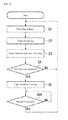
FIG. 5 illustrates an example of a sequence for the image displaying procedure for thelaser projector 1 according to one or more embodiments.
When the image displaying procedure is started in thelaser projector 1, then, as described above, the video processing portion 9 may perform a procedure for inputting a video signal inputted from the outside, and perform video processing (Steps S1 and S2). Light may be emitted from thelaser beam sources 2a through 2c and the scanning mirror 6 may be scanned (Step S3), so that the image is projected and displayed by the laser beams on the projection plane A. - If a voice that has been set in advance (an interrupt voice) from the
directional microphone 13 and/or thedirectional microphone 14 is detected when the image displaying procedure is being performed (Step S4), then thelevel controlling portion 12 may control thelaser controlling portion 10 to control the light emission levels of thelaser beam sources 2a through 2c (Step S5).
Given this, the control of the light emission in this way may be terminated through a restart instruction, inputted by an operator, or the like (Step S6), to return to the normal image displaying procedure. - If, for example, predetermined words, such as for example "Whoa!," "Ah!," and "Stop!", are set in the evaluating
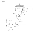
portion 12b, as illustrated inFIG. 6 , and one of the predetermined words, for example "Whoa!", produced in an exclamation by a person P1 who has entered into the illuminatedarea 20 is detected by thedirectional microphone 13, then the light emission levels of thelaser beam sources 2a through 2c may be controlled thereby.
Moreover, if a speaker or an operator P2 who is behind thelaser projector 1 exclaims a predetermined word, such as for example "Ah!" or "Stop!", because the person P1 has entered into the illuminatedarea 20, that word may be detected by thedirectional microphone 14, and the light emission levels of thelaser beam sources 2a through 2c may be limited thereby. - Although in the embodiments defined above vocalizations are detected by directional microphones and the light emission vocalizations of light sources are limited in response to recognition of predetermined words in those voices, according to one or more embodiments a level controlling portion may control the light emission levels (the light beam levels) in response to the detection, by a microphone, of any type of noise produced within the illuminated area 20 (that is, the sonic collection area 21), using a microphone that does not have any particular directionality. That is, depending on the requirements for, for example, precision of control, product design, and the like, according to one or more embodiments of the present invention, the image displaying device may not comprise the recognizing
portion 12a and the evaluatingportion 12b as described above. - Moreover, although in the embodiments defined above vocalizations are detected by directional microphones and the light emission vocalizations of light sources are limited in response to recognition of predetermined words in those voices, according to one or more embodiments a level controlling portion may control the light emission levels in response to the recognition of a voice from a sound, detected by a microphone, produced within the illuminated area 20 (that is, the sonic collection area 21), using a microphone that does not have any particular directionality. That is, according to one or more embodiments of the present invention, depending on the requirements for precision of control or product design, the evaluating
portion 12b may evaluate whether or not some type of voice has been recognized, and the light emission levels of the light source (the levels of the light beams) may be limited in response to the evaluatingportion 12b determining that a voice has been recognized. - Although in the embodiments defined above a
sonic collection area 21 essentially identical to the illuminatedarea 20 is formed from a singledirectional microphone 13 provided in theprojector 1, according to one or more embodiments a variety of different forms may be used. For example asonic collection area 21 that is substantially identical to the illuminatedarea 20 may be formed by respectivedirectional microphones area 20, as illustrated inFIG. 7 , or through covering the illuminatedarea 20 by a higher number ofdirectional microphones 13, each having a relatively small sonic collection area, as illustrated inFIG. 8 . - According to one or more embodiments, it is possible to modify the details of processing depending on words that have been recognized, to perform voice-recognition on the locations of a speaker or of a presenter and attendees in a presentation, to recognize the positions and the words that are vocalized. For instance, as illustrated in the example of
FIG. 9 , thedirectional microphone projector 1 to project the image. Moreover, in this case, a threshold value for the level at which thedirectional microphones laser projector 1 through a voice of an attendee P4 who is speaking softly or is relatively far away. - Moreover, as illustrated in the example of
FIG. 10 , the direction of projection may be changed depending on predetermined sounds, for example vocalizations such as "Higher," "Lower," "Right," or "Left," from an attendee P5 or a presenter P6. The projected scope may be varied in response to predetermined sounds, for example vocalizations such as "Wider" or "Narrower." Further, the brightness may be modified in response to predetermined sounds, for example vocalizations such as "Brighter" or "Less Bright". Additionally, an external video signal corresponding to a subsequent slide may be displayed, instead of a mouse click, in response to a predetermined sound, for example a vocalization such as "Next," or the like, by the presenter P6.
While the invention has been described with respect to a limited number of embodiments, those skilled in the art, having benefit of this disclosure, will appreciate that other embodiments can be devised which do not depart from the scope of the invention as defined by the claims. Furthermore, those of ordinary skill in the art would appreciate that certain components or "portions" of one or more embodiments of the present invention may be implemented by a circuit, processor, etc. using known methods. Accordingly, the scope of the invention should be limited only by the attached claims. -
- 1: Laser Projector
- 2a through 2c: Laser Beam Source Elements
- 10: Laser Controlling Portion
- 12: Level Controlling Portion
- 12a: Recognizing Portion
- 12b: Evaluating Portion
- 13, 14: Directional Microphones
- 20: Illuminated Area
- 21: Sonic Collection Area
- A: Projection Plane
Claims (10)
- An image displaying device (1) for projecting and displaying an image through a light beam, comprising:a microphone (13) configured to detect sounds within an illuminated area (20) illuminated by the light beam that projects the image; anda level controlling portion (12) configured to limit a level of the light beam that projects the image, when a sound has been detected by the microphone (13).
- The image displaying device (1) of claim 1, further comprising:a recognizing portion (12a) configured to recognize a predetermined sound from the sounds detected by the microphone (13); andan evaluating portion (12b) configured to evaluate whether the recognizing portion (12a) has recognized the predetermined sound, whereinthe level controlling portion (12) is configured to control the level of the light beam that projects the image in response to the evaluating portion (12b) having evaluated that the predetermined sound has been recognized.
- The image displaying device (1) of claim 2, wherein the predetermined sound is a noise from an object, a footstep noise, or a voice.
- The image displaying device (1) of claim 3, wherein
the evaluating portion (12b) is configured to evaluate whether or not a voice that has been recognized by the recognizing portion (12a) matches a predetermined word, and
the level controlling portion (12) is configured to limit the level of the light beam that projects the image in response to the evaluating portion (12b) having evaluated that there is a match between the recognized voice and the predetermined word. - The image displaying device (1) of any one of claims 1- 4, further comprising:a light source (2a-2c) configured to emit the light beam, whereinthe level controlling portion (12) is configured to control the level of the light beam that projects the image by limiting the light emission output of the light source (2a-2c).
- The image displaying device (1) of any one of claims 1-5, further comprising an additional microphone (14) configured to detect sounds outside the illuminated area (20).
- The image displaying device of any one of claims 1-6, wherein
each of the microphone (13) and of the additional microphone (14) is a directional microphone. - The image displaying device (1) of any one of claims 1-7, wherein a sonic collection area (21) in which the microphone (13) detects sounds is substantially identical to the illuminated area (20).
- The image displaying device (1) of any one of claims 1-8, wherein
a sonic collection area (21) in which the microphone (13) detects sounds is substantially the same as an area in which a person may be present. - The image displaying device (1) of claim 6 or claim 9 when dependent from claim 6, wherein a sonic collection area (22) in which the additional microphone (14) detects sounds is substantially the same as an area in which a person may be present.
Applications Claiming Priority (1)
| Application Number | Priority Date | Filing Date | Title |
|---|---|---|---|
| JP2012269915A JP2014115488A (en) | 2012-12-11 | 2012-12-11 | Image display device |
Publications (1)
| Publication Number | Publication Date |
|---|---|
| EP2744206A1 true EP2744206A1 (en) | 2014-06-18 |
Family
ID=49518729
Family Applications (1)
| Application Number | Title | Priority Date | Filing Date |
|---|---|---|---|
| EP13190922.8A Withdrawn EP2744206A1 (en) | 2012-12-11 | 2013-10-30 | Image projection device with microphone for proximity detection |
Country Status (3)
| Country | Link |
|---|---|
| US (1) | US20140160445A1 (en) |
| EP (1) | EP2744206A1 (en) |
| JP (1) | JP2014115488A (en) |
Cited By (2)
| Publication number | Priority date | Publication date | Assignee | Title |
|---|---|---|---|---|
| CN107300768A (en) * | 2016-03-31 | 2017-10-27 | 船井电机株式会社 | Projection arrangement |
| CN110168474A (en) * | 2017-02-24 | 2019-08-23 | 索尼移动通信株式会社 | Information processing equipment, information processing method and program |
Families Citing this family (3)
| Publication number | Priority date | Publication date | Assignee | Title |
|---|---|---|---|---|
| KR101774351B1 (en) * | 2013-06-26 | 2017-09-19 | 인텔 코포레이션 | A method and device for projecting an image with improved safety |
| JP6690152B2 (en) * | 2015-08-04 | 2020-04-28 | 富士ゼロックス株式会社 | Processor |
| US11610295B2 (en) * | 2019-12-09 | 2023-03-21 | Cnh Industrial America Llc | System and method for detecting the operating condition of components of an implement |
Citations (5)
| Publication number | Priority date | Publication date | Assignee | Title |
|---|---|---|---|---|
| JP2003044076A (en) | 2001-07-31 | 2003-02-14 | Fuji Photo Optical Co Ltd | Presentation system |
| JP2005241971A (en) | 2004-02-26 | 2005-09-08 | Seiko Epson Corp | Projector system, microphone device, projector control device, and projector |
| JP2005352172A (en) * | 2004-06-10 | 2005-12-22 | Sony Corp | Image projection apparatus and control method thereof |
| WO2011013605A1 (en) | 2009-07-27 | 2011-02-03 | 三洋電機株式会社 | Presentation system |
| US20110304833A1 (en) * | 2009-02-25 | 2011-12-15 | Kyocera Corporation | Mobile electronic device |
Family Cites Families (1)
| Publication number | Priority date | Publication date | Assignee | Title |
|---|---|---|---|---|
| US7972005B2 (en) * | 2007-04-02 | 2011-07-05 | Agere Systems Inc. | Computer projector method and apparatus having a safety feature for blacking out a portion of the image being projected onto a person |
-
2012
- 2012-12-11 JP JP2012269915A patent/JP2014115488A/en active Pending
-
2013
- 2013-10-04 US US14/046,176 patent/US20140160445A1/en not_active Abandoned
- 2013-10-30 EP EP13190922.8A patent/EP2744206A1/en not_active Withdrawn
Patent Citations (5)
| Publication number | Priority date | Publication date | Assignee | Title |
|---|---|---|---|---|
| JP2003044076A (en) | 2001-07-31 | 2003-02-14 | Fuji Photo Optical Co Ltd | Presentation system |
| JP2005241971A (en) | 2004-02-26 | 2005-09-08 | Seiko Epson Corp | Projector system, microphone device, projector control device, and projector |
| JP2005352172A (en) * | 2004-06-10 | 2005-12-22 | Sony Corp | Image projection apparatus and control method thereof |
| US20110304833A1 (en) * | 2009-02-25 | 2011-12-15 | Kyocera Corporation | Mobile electronic device |
| WO2011013605A1 (en) | 2009-07-27 | 2011-02-03 | 三洋電機株式会社 | Presentation system |
Cited By (4)
| Publication number | Priority date | Publication date | Assignee | Title |
|---|---|---|---|---|
| CN107300768A (en) * | 2016-03-31 | 2017-10-27 | 船井电机株式会社 | Projection arrangement |
| CN110168474A (en) * | 2017-02-24 | 2019-08-23 | 索尼移动通信株式会社 | Information processing equipment, information processing method and program |
| EP3588247A4 (en) * | 2017-02-24 | 2020-01-08 | Sony Mobile Communications Inc. | INFORMATION PROCESSING DEVICE, INFORMATION PROCESSING METHOD, AND PROGRAM |
| US10976648B2 (en) | 2017-02-24 | 2021-04-13 | Sony Mobile Communications Inc. | Information processing apparatus, information processing method, and program |
Also Published As
| Publication number | Publication date |
|---|---|
| US20140160445A1 (en) | 2014-06-12 |
| JP2014115488A (en) | 2014-06-26 |
Similar Documents
| Publication | Publication Date | Title |
|---|---|---|
| US20240353933A1 (en) | Display device and control device | |
| US9196067B1 (en) | Application specific tracking of projection surfaces | |
| US8274531B2 (en) | Display apparatus for projecting overlapping windows with light modulation valves | |
| US20140160445A1 (en) | Image displaying device | |
| US20100225743A1 (en) | Three-Dimensional (3D) Imaging Based on MotionParallax | |
| JP6231541B2 (en) | Image projection device | |
| US20120077172A1 (en) | Presentation system | |
| CN103765879A (en) | Method to extend laser depth map range | |
| US20160125221A1 (en) | Method for recognizing iris and electronic device thereof | |
| US20190349570A1 (en) | Scanning an object in three dimensions using color dashed line pattern | |
| WO2006041834A3 (en) | Interactive projection system and method | |
| US9282301B1 (en) | System for image projection | |
| WO2017073111A1 (en) | Light radiation device and light radiation method | |
| US9285906B2 (en) | Information processing apparatus, information display system and information display method | |
| CN104658462B (en) | Projector and projector control method | |
| JP2015079201A (en) | Video display system, video display method, and projection type video display device | |
| CN115112042A (en) | Detection device, detection method and space projection device | |
| US20160323553A1 (en) | Methods, systems, and computer readable media for improved illumination of spatial augmented reality objects | |
| KR102711579B1 (en) | projector control system | |
| JP2017123505A (en) | Content playback device, content playback method, and program | |
| WO2018078777A1 (en) | Aerial image display system, wavelength-selective image-forming device, image display device, aerial image display method | |
| JP2012181264A (en) | Projection device, projection method, and program | |
| KR20120129293A (en) | A method and a system for generating interactive contents based on augmented reality | |
| WO2022014441A1 (en) | Display device, display method, and program | |
| WO2023048630A1 (en) | A videoconferencing system and method with maintained eye contact |
Legal Events
| Date | Code | Title | Description |
|---|---|---|---|
| PUAI | Public reference made under article 153(3) epc to a published international application that has entered the european phase |
Free format text: ORIGINAL CODE: 0009012 |
|
| 17P | Request for examination filed |
Effective date: 20131030 |
|
| AK | Designated contracting states |
Kind code of ref document: A1 Designated state(s): AL AT BE BG CH CY CZ DE DK EE ES FI FR GB GR HR HU IE IS IT LI LT LU LV MC MK MT NL NO PL PT RO RS SE SI SK SM TR |
|
| AX | Request for extension of the european patent |
Extension state: BA ME |
|
| STAA | Information on the status of an ep patent application or granted ep patent |
Free format text: STATUS: THE APPLICATION IS DEEMED TO BE WITHDRAWN |
|
| 18D | Application deemed to be withdrawn |
Effective date: 20141219 |