EP2744041A1 - Système de protection parafoudre pour radôme et procédé de montage associé - Google Patents
Système de protection parafoudre pour radôme et procédé de montage associé Download PDFInfo
- Publication number
- EP2744041A1 EP2744041A1 EP13196687.1A EP13196687A EP2744041A1 EP 2744041 A1 EP2744041 A1 EP 2744041A1 EP 13196687 A EP13196687 A EP 13196687A EP 2744041 A1 EP2744041 A1 EP 2744041A1
- Authority
- EP
- European Patent Office
- Prior art keywords
- radome
- antenna
- wall
- lightning protection
- segment
- Prior art date
- Legal status (The legal status is an assumption and is not a legal conclusion. Google has not performed a legal analysis and makes no representation as to the accuracy of the status listed.)
- Granted
Links
Images




Classifications
-
- H—ELECTRICITY
- H01—ELECTRIC ELEMENTS
- H01Q—ANTENNAS, i.e. RADIO AERIALS
- H01Q1/00—Details of, or arrangements associated with, antennas
- H01Q1/002—Protection against seismic waves, thermal radiation or other disturbances, e.g. nuclear explosion; Arrangements for improving the power handling capability of an antenna
-
- B—PERFORMING OPERATIONS; TRANSPORTING
- B64—AIRCRAFT; AVIATION; COSMONAUTICS
- B64D—EQUIPMENT FOR FITTING IN OR TO AIRCRAFT; FLIGHT SUITS; PARACHUTES; ARRANGEMENT OR MOUNTING OF POWER PLANTS OR PROPULSION TRANSMISSIONS IN AIRCRAFT
- B64D45/00—Aircraft indicators or protectors not otherwise provided for
- B64D45/02—Lightning protectors; Static dischargers
-
- H—ELECTRICITY
- H01—ELECTRIC ELEMENTS
- H01Q—ANTENNAS, i.e. RADIO AERIALS
- H01Q1/00—Details of, or arrangements associated with, antennas
- H01Q1/27—Adaptation for use in or on movable bodies
- H01Q1/28—Adaptation for use in or on aircraft, missiles, satellites, or balloons
-
- H—ELECTRICITY
- H01—ELECTRIC ELEMENTS
- H01Q—ANTENNAS, i.e. RADIO AERIALS
- H01Q1/00—Details of, or arrangements associated with, antennas
- H01Q1/27—Adaptation for use in or on movable bodies
- H01Q1/28—Adaptation for use in or on aircraft, missiles, satellites, or balloons
- H01Q1/281—Nose antennas
-
- H—ELECTRICITY
- H01—ELECTRIC ELEMENTS
- H01Q—ANTENNAS, i.e. RADIO AERIALS
- H01Q1/00—Details of, or arrangements associated with, antennas
- H01Q1/42—Housings not intimately mechanically associated with radiating elements, e.g. radome
-
- H—ELECTRICITY
- H01—ELECTRIC ELEMENTS
- H01Q—ANTENNAS, i.e. RADIO AERIALS
- H01Q1/00—Details of, or arrangements associated with, antennas
- H01Q1/50—Structural association of antennas with earthing switches, lead-in devices or lightning protectors
-
- Y—GENERAL TAGGING OF NEW TECHNOLOGICAL DEVELOPMENTS; GENERAL TAGGING OF CROSS-SECTIONAL TECHNOLOGIES SPANNING OVER SEVERAL SECTIONS OF THE IPC; TECHNICAL SUBJECTS COVERED BY FORMER USPC CROSS-REFERENCE ART COLLECTIONS [XRACs] AND DIGESTS
- Y10—TECHNICAL SUBJECTS COVERED BY FORMER USPC
- Y10T—TECHNICAL SUBJECTS COVERED BY FORMER US CLASSIFICATION
- Y10T29/00—Metal working
- Y10T29/49—Method of mechanical manufacture
- Y10T29/49002—Electrical device making
- Y10T29/49016—Antenna or wave energy "plumbing" making
- Y10T29/49018—Antenna or wave energy "plumbing" making with other electrical component
Definitions
- the invention relates to a lightning protection system for a radome and a method of mounting a lightning protection system on a radome.
- the invention finds a particularly advantageous application for aircraft radomes.
- Lightning can cause significant damage to aircraft in flight.
- a first known surge protection system consists of metal strips positioned on the outer face of the radome.
- the figure 1 illustrates this device.
- the metal strips b are arranged radially on the outer face of the radome, starting from the periphery of the radome and targeting the tip P thereof.
- the metal strips are electrically connected to the mass of the aircraft. When lightning strikes the radome, the metal strips b guide the lightning to the mass of the aircraft.
- the figure 2 illustrates the connection between a metal stud 1 which is flush with the outer wall of the radome and a lightning protection strip b located on the inner face of the radome.
- the metal stud 1 is fixed in the wall of the radome R via a spacer EN and the metal strip b is screwed to the metal stud 1.
- the lightning F striking the metal stud 1 on the side of the outer wall 2 of the radome is then guided until to the band b located on the side of the inner wall 3 of the radome.
- the position of the metal strips continues to disturb the radiation that is emitted by the antenna. Indeed, because of the presence of the metal strips b arranged radially on the inner face of the radome, the total energy emitted in the distance is less than the total energy that would be emitted in the absence of bands. Similarly, the radiation pattern is also disturbed compared to the diagram that would be obtained in the absence of bands.
- the invention does not have the disadvantages mentioned above.
- the invention relates to a lightning protection system for antenna radome, the antenna being able to radiate towards an inner wall of the radome an electric field having a predetermined rectilinear polarization direction, the system comprising at least a lightning protection strip positioned on an inner wall of the radome, characterized in that the lightning protection strip defines, on the inner wall of the radome, a curve which is substantially perpendicular, in each of its points, to the rectilinear polarization direction predetermined vector of the electric field.
- the curve defined by the lightning protection band is substantially perpendicular to a set of segments, each segment of the set of segments corresponding, for a misalignment of the antenna, to a projection, on the inner wall of the radome, according to a direction perpendicular to a plane which contains the antenna, a line segment centered on a central radiating rectilinear element of the antenna and having a direction parallel to the predetermined polarization direction of the electric field vector capable of being radiated by said a central radiating rectilinear element, the determination of the set of segments being carried out for a plurality of misalignments of the antenna.
- the curve defined by the surge protection band is substantially perpendicular to at least one additional segment which is an extension, towards the periphery of the radome and to a point situated near a outline which delimits an illumination zone of the radome, of a projected segment which corresponds to an abutment of the antenna, the prolongation of said segment corresponding to an intersection between the inner wall of the radome and a plane which comprises the segment of right centered on said rectilinear element and said projected segment.
- the lightning protection strip is connected to an electrical mass located beyond the contour which delimits the illumination zone of the radome.
- the plurality of detents of the antenna embraces the entire radio window of the antenna.
- the invention also relates to a device comprising a radome and an antenna capable of radiating towards an inner wall of the radome an electric field having a predetermined rectilinear polarization direction, the radome being provided with a lightning protection system, characterized in that that the lightning protection system is a system according to the invention.
- the invention also relates to an aircraft comprising a device comprising a radome and an antenna capable of radiating towards an inner wall of the radome an electric field having a predetermined rectilinear polarization direction, characterized in that the device is a device according to the invention.
- the invention also relates to a method of mounting a lightning protection system on an inner wall of a radome, the antenna being able to radiating towards the inner wall of the radome an electric field having a predetermined rectilinear polarization direction, the method comprising mounting at least one lightning protection strip on the inner wall of the radome, characterized in that the mounting of the strip protection device is carried out in such a way that said band follows a substantially perpendicular curve, at each of its points, to the predetermined rectilinear polarization direction of the electric field vector.
- the figure 3 represents, by way of non-limiting example, a front view of the inner wall of a radome equipped with a lightning protection system according to the invention.
- the lightning protection system comprises six metal strips b 1 -b 6 distributed on the inner wall of the radome.
- Each lightning protection band defines a curve which is substantially perpendicular, at each of its points, to the rectilinear polarization direction of the electric field vector radiated by an antenna that faces the radome.
- the antenna that faces the radome (not shown in the figure) is a flat antenna that radiates an electromagnetic wave whose electric field is polarized at 45 ° straight.
- the direction of polarization of the vector of the electric field radiated by the antenna is symbolically represented by the segments S 1 , S 2 , ..., S j ,..., S N , the construction of which is detailed with reference to FIGS. Figures 7A-7B of the present description.
- Each lightning protection strip is connected to the outside of the radome by a set of metal studs 1 as described above with reference to FIG. figure 2 .
- the illumination zone of the internal wall of the radome is delimited by the closed curve E.
- each protective lightning arrester strip is connected to the mass of the aircraft.
- the most centered portion of the radome is devoid of lightning protection band (zone of the radome inside the circle C shown in FIG. figure 3 ).
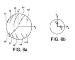
- FIGS. 4A-4B, 5A-5B and 6A-6B illustrate, symbolically, three lightning protection systems of the invention which correspond, respectively, to three different rectilinear polarizations of the radiated electromagnetic wave.
- the Figures 4A-4B illustrate, in a symbolic way, the case represented in detail by the figure 3 and which corresponds to a radiated wave polarized at 45 °.
- the Figure 4A illustrates the position of lightning protection strips on the inner wall of the radome and the Figure 4B illustrates the configuration of the corresponding electromagnetic field radiated by the antenna.
- the Figures 5A-5B illustrate, symbolically, the case of a vertically polarized radiated wave.
- the Figure 5A illustrates the position of lightning protection strips on the inner wall of the radome and the Figure 5B illustrates the configuration of the corresponding electromagnetic field radiated by the antenna.
- the Figures 6A-6B illustrate, symbolically, the case of a horizontally polarized radiated wave.
- the Figure 6A illustrates the position of lightning protection strips on the inner wall of the radome and the Figure 6B illustrates the configuration of the corresponding electromagnetic field radiated by the antenna.
- connection according to the invention of the orientation of the lightning protection strips with the direction of rectilinear polarization of the electric field of the wave radiated by the antenna has many advantages. Indeed, it results from this connection, a very clear decrease in the loss of transparency of the radome, for example a decrease of the order of 3%. It is then possible to achieve a gain in range and sensitivity in the detection of weather phenomena. It also results from this connection a very sharp decrease in the deformation of the beam emitted by the antenna resulting in a decrease, for example 3dB, of the rise in the level of the side lobes generated by the presence of the radome.
- the reliability of the meteorological detection is thus improved by avoiding, for example, that the possible reflections of the secondary lobes on a cloud not situated in the axis of the antenna are taken into account.
- the influence of ground echoes is reduced, which improves the quality of the received signal and decreases the probability of false alarm on the windshear detection system or PWS (Predictive WindShear) system.
- the axis deviation of the beam is decreased, thus favoring the accuracy of the mapping or target tracking systems.
- FIGS. 7A and 7B represent respectively, by way of non-limiting example, a front view and a cross-sectional view of the inner wall of a radome on which is represented a geometric figure adapted to assist in the positioning of the lightning protection strips according to the example represented in figure 3 .
- the electromagnetic wave radiated towards the radome is a wave whose electric field is polarized rectilinearly at 45 °.
- the figure 8 illustrates the front view of a radar antenna panel that radiates such a wave.
- the surface of the antenna defines a circle centered in an orthogonal reference (X, Y), the X and Y axes being respectively confused with a horizontal and with a vertical when the aircraft is on the ground.
- the antenna is able to move around each of the X and Y axes (rotation in azimuth around the Y axis and rotation in elevation around the Y axis).
- the antenna is provided with a set of slots F 1 , F 2 , ..., F N etc.
- a central slot F C passes through the center of the circle defined by the panel.
- the polarization of the radiated electric field is rectilinear.
- Each slot radiates an electromagnetic wave whose electric field has a direction perpendicular to the axis of the slot.
- a segment S i corresponds to a projection, on the inner wall of the radome and in a direction perpendicular to a plane which contains the surface of the antenna, of a line segment centered on the central rectilinear element F C and having a direction parallel to the direction of polarization of the vector electric field radiated by said central radiating rectilinear element.
- the length of the line segment centered on the central rectilinear element is chosen, for example, equal to 15 cm. Other values are however possible, for example 10cm or 20cm.
- the projection of the line segment centered on the central rectilinear element is performed for a plurality of misalignments of the antenna including the zero misalignment (projection in the axis of the antenna) and the misalignments which put the antenna in abutment.
- the plurality of detents of the antenna embraces the entire radio window of the antenna.
- the projected segments corresponding to the cases where the antenna is in abutment are extended towards the periphery of the radome.
- the extension of the projected segment then corresponds to the intersection between the inner wall of the radome and a plane that includes the straight line segment centered on the rectilinear element and the projected segment.
- the projected segment S k thus extends the projected segment S j .
- the mounting of a metal strip on the internal face of the radome is done by joining selected trace points. so that the curve drawn by these points is substantially perpendicular to the segments it intercepts.
- the distance separating two successive plot points is, for example, equal to 20 cm in curvilinear distance.
- a number of passage points between the exterior and interior of the radome are also drawn for the passage of the screws for fixing the metal strip.
- the metal strip can either be rigid (and thus have been previously put in good shape), or be flexible to better conform to the desired shape.
- the invention has been more particularly described for an embedded radome application in an aircraft. More generally, however, the invention applies to any type of radome associated with an antenna, embedded or not.
Landscapes
- Engineering & Computer Science (AREA)
- Aviation & Aerospace Engineering (AREA)
- Physics & Mathematics (AREA)
- Astronomy & Astrophysics (AREA)
- General Physics & Mathematics (AREA)
- Remote Sensing (AREA)
- Details Of Aerials (AREA)
Abstract
Description
- L'invention concerne un système de protection parafoudre pour radôme ainsi qu'un procédé de montage de système de protection parafoudre sur un radôme.
- L'invention trouve une application particulièrement avantageuse pour les radômes d'aéronef.
- La foudre peut produire d'importants dommages aux aéronefs en vol. Afin de protéger les aéronefs et de minimiser les dégâts pouvant être occasionnés par la foudre, il est connu de placer des bandes de protection parafoudre sur le radôme des aéronefs.
- Un premier système de protection parafoudre connu est constitué de bandes métalliques positionnées sur la face externe du radôme. La
figure 1 illustre ce dispositif. Afin de minimiser les problèmes d'aérodynamisme, les bandes métalliques b sont disposées de façon radiale sur la face externe du radôme, partant de la périphérie du radôme et visant la pointe P de celui-ci. Les bandes métalliques sont électriquement reliées à la masse de l'aéronef. Lorsque la foudre frappe le radôme, les bandes métalliques b guident la foudre jusqu'à la masse de l'aéronef. - Afin de supprimer le problème d'aérodynamisme, il est connu de l'art antérieur un système dans lequel les bandes métalliques sont positionnées à l'intérieur du radôme, l'attachement de la foudre sur le radôme s'opérant alors à l'aide de plots métalliques qui affleurent la paroi externe du radôme. Un tel système est décrit dans la demande de brevet d'invention déposée par la Demanderesse, en date du
11 Décembre 2007, sous le N°07 59733 figure 2 illustre la liaison entre un plot métallique 1 qui affleure la paroi externe du radôme et une bande de protection parafoudre b située sur la face interne du radôme. Le plot métallique 1 est fixé dans la paroi du radôme R via une entretoise EN et la bande métallique b est vissée au plot métallique 1. La foudre F qui frappe le plot métallique 1 du côté de la paroi externe 2 du radôme est alors guidée jusqu'à la bande b située du côté de la paroi interne 3 du radôme. - Si ce deuxième dispositif permet de résoudre le problème d'aérodynamisme, la position des bandes métalliques continue de perturber le rayonnement qui est émis par l'antenne. En effet, du fait de la présence des bandes métalliques b disposées radialement sur la face interne du radôme, l'énergie totale émise au loin est inférieure à l'énergie totale qui serait émise en l'absence de bandes. De même, le diagramme de rayonnement est également perturbé par rapport au diagramme qui serait obtenu en l'absence de bandes.
- L'invention ne présente pas les inconvénients mentionnés ci-dessus.
- En effet, l'invention concerne un système de protection parafoudre pour radôme d'antenne, l'antenne étant apte à rayonner en direction d'une paroi interne du radôme un champ électrique ayant une direction de polarisation rectiligne prédéterminée, le système comprenant au moins une bande de protection parafoudre positionnée sur une paroi interne du radôme, caractérisé en ce que la bande de protection parafoudre définit, sur la paroi interne du radôme, une courbe qui est sensiblement perpendiculaire, en chacun de ses points, à la direction de polarisation rectiligne prédéterminée du vecteur champ électrique.
- Dans le cadre de l'invention, l'expression « sensiblement perpendiculaire » doit s'entendre, par exemple, comme perpendiculaire à plus ou moins 25°.
- Selon une caractéristique supplémentaire de l'invention, la courbe définie par la bande de protection parafoudre est sensiblement perpendiculaire à un ensemble de segments, chaque segment de l'ensemble de segments correspondant, pour un dépointage de l'antenne , à une projection, sur la paroi interne du radôme, selon une direction perpendiculaire à un plan qui contient l'antenne, d'un segment de droite centré sur un élément rectiligne rayonnant central de l'antenne et ayant une direction parallèle à la direction de polarisation prédéterminée du vecteur champ électrique susceptible d'être rayonné par ledit élément rectiligne rayonnant central, la détermination de l'ensemble de segments étant effectuée pour une pluralité de dépointages de l'antenne.
- Selon une autre caractéristique supplémentaire de l'invention, la courbe définie par la bande de protection parafoudre est sensiblement perpendiculaire à au moins un segment supplémentaire qui est une prolongation, vers la périphérie du radôme et jusqu'à un point situé à proximité d'un contour qui délimite une zone d'éclairement du radôme, d'un segment projeté qui correspond à une mise en butée de l'antenne, la prolongation dudit segment correspondant à une intersection entre la paroi interne du radôme et un plan qui comprend le segment de droite centré sur ledit élément rectiligne et ledit segment projeté.
- Selon encore une autre caractéristique supplémentaire de l'invention, la bande de protection parafoudre est reliée à une masse électrique située au-delà du contour qui délimite la zone d'éclairement du radôme.
- Selon encore une autre caractéristique supplémentaire de l'invention, la pluralité de dépointages de l'antenne embrasse la totalité de la fenêtre radioélectrique de l'antenne.
- L'invention concerne également un dispositif comprenant un radôme et une antenne apte à rayonner en direction d'une paroi interne du radôme un champ électrique ayant une direction de polarisation rectiligne prédéterminée, le radôme étant muni d'un système de protection parafoudre, caractérisé en ce que le système de protection parafoudre est un système conforme à l'invention.
- L'invention concerne également un aéronef comprenant un dispositif comportant un radôme et une antenne apte à rayonner en direction d'une paroi interne du radôme un champ électrique ayant une direction de polarisation rectiligne prédéterminée, caractérisé en ce que le dispositif est un dispositif conforme à l'invention.
- L'invention concerne également un procédé de montage de système de protection parafoudre sur une paroi interne d'un radôme, l'antenne étant apte à rayonner en direction de la paroi interne du radôme un champ électrique ayant une direction de polarisation rectiligne prédéterminée, le procédé comprenant le montage d'au moins une bande de protection parafoudre sur la paroi interne du radôme, caractérisé en ce que le montage de la bande de protection parafoudre est effectué de telle sorte que ladite bande suive une courbe sensiblement perpendiculaire, en chacun de ses points, à la direction de polarisation rectiligne prédéterminée du vecteur champ électrique..
- Selon une caractéristique supplémentaire du procédé de l'invention :
- une détermination d'un ensemble de segments est effectuée, chaque segment de l'ensemble de segments étant déterminé, pour un dépointage de l'antenne, par une projection, sur la paroi interne du radôme, selon une direction perpendiculaire à un plan qui contient l'antenne, d'un segment de droite centré sur un élément rectiligne rayonnant central de l'antenne et ayant une direction parallèle à la direction de polarisation rectiligne prédéterminée du vecteur champ électrique susceptible d'être rayonné par ledit élément rectiligne rayonnant central , la détermination de l'ensemble de segments étant effectuée pour une pluralité de dépointages de l'antenne, et
- la bande de protection parafoudre est disposée sur la paroi interne du radôme de façon que les segments interceptés par ladite bande le soient sensiblement perpendiculairement.
- Selon une caractéristique supplémentaire du procédé de l'invention :
- la détermination de l'ensemble de segments comprend, en outre, pour les dépointages qui mettent l'antenne en butée, une prolongation du segment projeté vers la périphérie du radôme jusqu'à un point situé à proximité d'un contour qui délimite une zone d'éclairement du radôme, la prolongation du segment correspondant à une intersection entre la paroi interne du radôme et un plan qui comprend le segment de droite centré sur l'élément rectiligne et le segment projeté, et
- la bande de protection parafoudre est prolongée sur la paroi interne du radôme de façon qu'un segment projeté qui résulte de la prolongation soit intercepté sensiblement perpendiculairement par ladite bande.
- D'autres caractéristiques et avantages de l'invention apparaîtront à la lecture d'un mode de réalisation préférentiel fait en référence aux figures jointes, parmi lesquelles :
- La
figure 1 , déjà décrite, représente un premier système de protection parafoudre selon l'art antérieur; - La
figure 2 , déjà décrite, représente une vue de détail d'un deuxième système de protection parafoudre selon l'art antérieur ; - La
figures 3 représente, à titre d'exemple non limitatif, une vue de face de la paroi interne d'un radôme équipé d'un système de protection parafoudre selon l'invention; - Les
figures 4A-4B, 5A-5B et6A-6B illustrent, de façon symbolique, trois systèmes de protection parafoudre selon l'invention qui correspondent, respectivement, à trois polarisations rectilignes différentes de l'onde électromagnétique rayonnée ; - Les
figures 7A et7B représentent, à titre d'exemple non limitatif, des figures géométriques aptes à la mise en place du système de protection parafoudre représenté enfigure 3 ; - La
figure 8 représente un panneau d'antenne radar apte à la conception des figures géométriques représentées sur lesfigures 7A et7B . - Sur toutes les figures, les mêmes références désignent les mêmes éléments.
- La
figure 3 représente, à titre d'exemple non limitatif, une vue de face de la paroi interne d'un radôme équipé d'un système de protection parafoudre selon l'invention. - Le système de protection parafoudre selon l'invention comprend six bandes métalliques b1-b6 réparties sur la paroi interne du radôme. Chaque bande de protection parafoudre définit une courbe qui est sensiblement perpendiculaire, en chacun de ses points, à la direction de polarisation rectiligne du vecteur champ électrique rayonné par une antenne qui fait face au radôme. Selon l'exemple choisi, l'antenne qui fait face au radôme (non représentée sur la figure) est une antenne plate qui rayonne une onde électromagnétique dont le champ électrique est polarisé rectilignement à 45°. La direction de polarisation du vecteur champ électrique rayonné par l'antenne est représentée, de façon symbolique, par les segments S1, S2, ..., Sj, ..., SN dont la construction est détaillée en référence aux
figures 7A-7B de la présente description. - Chaque bande de protection parafoudre est reliée à l'extérieur du radôme par un ensemble de plots métalliques 1 tels que décrits précédemment en référence à la
figure 2 . La zone d'éclairement de la paroi interne du radôme est délimitée par la courbe fermée E. Au-delà de la courbe E, chaque bande de protection parafoudre est reliée à la masse de l'aéronef. De façon connue en soi également, la partie la plus centrée du radôme est dépourvue de bande de protection parafoudre (zone du radôme à l'intérieur du cercle C représenté sur lafigure 3 ). - Les
figures 4A-4B, 5A-5B et6A-6B illustrent, de façon symbolique, trois systèmes de protection parafoudre de l'invention qui correspondent, respectivement, à trois polarisations rectilignes différentes de l'onde électromagnétique rayonnée. - Les
figures 4A-4B illustrent, de façon symbolique, le cas représenté en détail par lafigure 3 et qui correspond à une onde rayonnée polarisée à 45°. Lafigure 4A illustre la position de bandes de protection parafoudre sur la paroi interne du radôme et lafigure 4B illustre la configuration du champ électromagnétique correspondant rayonnée par l'antenne. - Les
figures 5A-5B illustrent, de façon symbolique, le cas d'une onde rayonnée polarisée verticalement. Lafigure 5A illustre la position de bandes de protection parafoudre sur la paroi interne du radôme et lafigure 5B illustre la configuration du champ électromagnétique correspondant rayonnée par l'antenne. - Les
figures 6A-6B illustrent, de façon symbolique, le cas d'une onde rayonnée polarisée horizontalement. Lafigure 6A illustre la position de bandes de protection parafoudre sur la paroi interne du radôme et lafigure 6B illustre la configuration du champ électromagnétique correspondant rayonnée par l'antenne. - Sur toutes les figures, il apparaît un positionnement des bandes de protection parafoudre sensiblement perpendiculaire à la direction du vecteur champ électrique rayonné.
- La mise en relation, selon l'invention, de l'orientation des bandes de protection parafoudre avec la direction de polarisation rectiligne du champ électrique de l'onde rayonnée par l'antenne présente de nombreux avantages. En effet, il résulte de cette mise en relation, une très nette diminution de la perte en transparence du radôme, par exemple une diminution de l'ordre de 3%. Il est alors possible de réaliser un gain de portée et de sensibilité dans la détection des phénomènes météorologiques. Il résulte également de cette mise en relation une très nette diminution de la déformation du faisceau émis par l'antenne entraînant ainsi une baisse, par exemple de 3dB, des remontées du niveau des lobes secondaires générés par la présence du radôme. La fiabilité de la détection météorologique est ainsi améliorée en évitant, par exemple, que les éventuelles réflexions des lobes secondaires sur un nuage non situé dans l'axe de l'antenne soient prises en compte. De même, l'influence des échos de sol est diminuée, ce qui améliore la qualité du signal reçu et diminue les probabilités de fausse alerte sur le système de détection de cisaillement de vent ou système PWS (PWS pour « Predictive WindShear). Egalement, la déviation d'axe du faisceau est diminuée, favorisant ainsi la précision des systèmes de cartographie ou de suivi de cibles.
- Les
figures 7A et7B représentent respectivement, à titre d'exemple non limitatif, une vue de face et une vue en coupe transversale de la paroi interne d'un radôme sur laquelle est représentée une figure géométrique apte à aider au positionnement des bandes de protection parafoudre selon l'exemple représenté enfigure 3 . - L'onde électromagnétique rayonnée en direction du radôme est une onde dont le champ électrique est polarisé rectilignement à 45°. La
figure 8 illustre la vue de face d'un panneau d'antenne radar qui rayonne une telle onde. La surface de l'antenne définit un cercle centré dans un repère orthogonal (X, Y), les axes X et Y se confondant respectivement avec une horizontale et avec une verticale lorsque l'aéronef est au sol. L'antenne est apte à se mouvoir autour de chacun des axes X et Y (rotation en azimut autour de l'axe Y et rotation en élévation autour de l'axe Y). L'antenne est munie d'un ensemble de fentes F1, F2, ..., FN etc. orientées à 45° dans le repère (X, Y). Parmi ces fentes, une fente centrale FC passe par le centre du cercle défini par le panneau. La polarisation du champ électrique rayonné est rectiligne. Chaque fente rayonne une onde électromagnétique dont le champ électrique a une direction perpendiculaire à l'axe de la fente. - La figure géométrique de la
figure 7A représente une vue de face d'un ensemble de segments Si (i=1, 2, ..., N) répartis sur la paroi interne du radôme. Ces segments sont inscrits dans la courbe fermée E qui délimite la zone d'éclairement de la paroi interne du radôme pour tous les dépointages possibles de l'antenne. - Pour un dépointage d'antenne donné, un segment Si correspond à une projection, sur la paroi interne du radôme et selon une direction perpendiculaire à un plan qui contient la surface de l'antenne, d'un segment de droite centré sur l'élément rectiligne central FC et ayant une direction parallèle à la direction de polarisation du vecteur champ électrique rayonné par ledit élément rectiligne rayonnant central. Pour une antenne de diamètre égal à 70cm, la longueur du segment de droite centré sur l'élément rectiligne central est choisie, par exemple, égale à 15cm. D'autres valeurs sont toutefois possibles, par exemple 10cm ou 20cm. La projection du segment de droite centré sur l'élément rectiligne central est effectuée pour une pluralité de dépointages de l'antenne incluant le dépointage nul (projection dans l'axe de l'antenne) et les dépointages qui mettent l'antenne en butée. De façon préférentielle, la pluralité de dépointages de l'antenne embrasse la totalité de la fenêtre radioélectrique de l'antenne.
- Selon l'invention, les segments projetés qui correspondent aux cas où l'antenne est en butée sont prolongés vers la périphérie du radôme. La prolongation du segment projeté correspond alors à l'intersection entre la paroi interne du radôme et un plan qui comprend le segment de droite centré sur l'élément rectiligne et le segment projeté. En référence à la
figure 7A , le segment projeté Sk prolonge ainsi le segment projeté Sj. - Une fois établie la géométrie des segments Si, le montage d'une bande métallique sur la face interne du radôme s'effectue en joignant des points de tracé choisis de façon que la courbe dessinée par ces points soit sensiblement perpendiculaire aux segments qu'elle intercepte. La distance qui sépare deux points de tracé successifs est, par exemple, égale à 20cm en distance curviligne. Un certain nombre de points de passage entre extérieur et intérieur du radôme sont également tracés pour le passage des vis destinées à fixer la bande métallique. La bande métallique peut soit être rigide (et donc avoir été préalablement mise à la bonne forme), soit être souple pour mieux se conformer à la forme souhaitée.
- Dans la description qui précède, l'invention a été plus particulièrement décrite pour une application de radôme embarqué dans un aéronef. De façon plus générale cependant, l'invention s'applique à tout type de radôme associé à une antenne, embarqué ou non.
Claims (12)
- Système de protection parafoudre pour radôme d'antenne, l'antenne étant apte à rayonner en direction d'une paroi interne du radôme un champ électrique ayant une direction de polarisation rectiligne prédéterminée, le système comprenant au moins une bande de protection parafoudre positionnée sur une paroi interne du radôme, caractérisé en ce que la bande de protection parafoudre définit, sur la paroi interne du radôme, une courbe qui est sensiblement perpendiculaire, en chacun de ses points, à la direction de polarisation rectiligne prédéterminée du vecteur champ électrique.
- Système selon la revendication 1, dans lequel la courbe définie par la bande de protection parafoudre est sensiblement perpendiculaire à un ensemble de segments (S1, S2, ..., SN), chaque segment de l'ensemble de segments correspondant, pour un dépointage de l'antenne , à une projection, sur la paroi interne du radôme, selon une direction perpendiculaire à un plan qui contient l'antenne, d'un segment de droite centré sur un élément rectiligne rayonnant central (FC) de l'antenne et ayant une direction parallèle à la direction de polarisation prédéterminée du vecteur champ électrique susceptible d'être rayonné par ledit élément rectiligne rayonnant central, la détermination de l'ensemble de segments étant effectuée pour une pluralité de dépointages de l'antenne.
- Système selon la revendication 2, dans lequel la courbe définie par la bande de protection parafoudre est sensiblement perpendiculaire à au moins un segment supplémentaire qui est une prolongation, vers une périphérie du radôme et jusqu'à un point situé à proximité d'un contour (E) qui délimite une zone d'éclairement du radôme, d'un segment projeté qui correspond à une mise en butée de l'antenne, la prolongation dudit segment correspondant à une intersection entre la paroi interne du radôme et un plan qui comprend le segment de droite centré sur ledit élément rectiligne et ledit segment projeté.
- Système selon la revendication 3, dans lequel la bande de protection parafoudre (b1, b2, ..., b6) est reliée à une masse électrique située au-delà du contour (E) qui délimite la zone d'éclairement du radôme.
- Système selon l'une quelconque des revendications 2 à 4, dans lequel la pluralité de dépointages de l'antenne embrasse la totalité de la fenêtre radioélectrique de l'antenne.
- Dispositif comprenant un radôme (R) et une antenne (A) apte à rayonner en direction d'une paroi interne du radôme un champ électrique ayant une direction de polarisation rectiligne prédéterminée, le radôme étant muni d'un système de protection parafoudre, caractérisé en ce que le système de protection parafoudre est un système conforme à l'une quelconque des revendications 1 à 5.
- Aéronef comprenant un dispositif comportant un radôme (R) et une antenne (A) apte à rayonner en direction d'une paroi interne du radôme un champ électrique ayant une direction de polarisation rectiligne prédéterminée, caractérisé en ce que le dispositif est un dispositif selon la revendication 6.
- Procédé de montage de système de protection parafoudre sur une paroi interne d'un radôme d'antenne, l'antenne étant apte à rayonner en direction de la paroi interne du radôme un champ électrique ayant une direction de polarisation rectiligne prédéterminée, le procédé comprenant le montage d'au moins une bande de protection parafoudre sur la paroi interne du radôme, caractérisé en ce que le montage de la bande de protection parafoudre est effectué de sorte que la bande de protection parafoudre suive une courbe sensiblement perpendiculaire, en chacun de ses points, à la direction de polarisation rectiligne prédéterminée du vecteur champ électrique.
- Procédé de montage selon la revendication 8, dans lequel est effectuée une détermination d'un ensemble de segments (S1, S2, ..., SN), chaque segment de l'ensemble de segments étant déterminé, pour un dépointage de l'antenne, par une projection sur la paroi interne du radôme, selon une direction perpendiculaire à un plan qui contient l'antenne, d'un segment de droite centré sur un élément rectiligne rayonnant central (FC) de l'antenne et ayant une direction parallèle à la direction de polarisation rectiligne prédéterminée du vecteur champ électrique susceptible d'être rayonné par ledit élément rectiligne rayonnant central, la détermination de l'ensemble de segments étant effectuée pour une pluralité de dépointages de l'antenne, la bande de protection parafoudre étant disposée sur la paroi interne du radôme de façon que les segments interceptés par ladite bande le soient sensiblement perpendiculairement.
- Procédé de montage selon la revendication 9, dans lequel la détermination de l'ensemble de segments comprend, en outre, pour les dépointages qui mettent l'antenne en butée, une prolongation du segment projeté vers la périphérie du radôme jusqu'à un point situé à proximité d'un contour (E) qui délimite une zone d'éclairement du radôme, la prolongation du segment correspondant à une intersection entre la paroi interne du radôme et un plan qui comprend le segment de droite centré sur l'élément rectiligne et le segment projeté, la bande de protection parafoudre étant prolongée sur la paroi interne du radôme de façon qu'un segment projeté qui résulte de la prolongation soit intercepté sensiblement perpendiculairement par ladite bande (b1, b2, ..., b6).
- Procédé selon la revendication 10, dans lequel la bande de protection parafoudre (b1, b2, ..., b6) est reliée à une masse électrique située au-delà du contour (E) qui délimite la zone d'éclairement du radôme.
- Procédé selon l'une quelconque des revendications 9 à 11, dans lequel la pluralité de dépointages de l'antenne embrasse la totalité de la fenêtre radioélectrique de l'antenne.
Applications Claiming Priority (1)
| Application Number | Priority Date | Filing Date | Title |
|---|---|---|---|
| FR1262065A FR2999814B1 (fr) | 2012-12-14 | 2012-12-14 | Systeme de protection parafoudre pour radome et procede de montage associe |
Publications (2)
| Publication Number | Publication Date |
|---|---|
| EP2744041A1 true EP2744041A1 (fr) | 2014-06-18 |
| EP2744041B1 EP2744041B1 (fr) | 2023-11-22 |
Family
ID=48170597
Family Applications (1)
| Application Number | Title | Priority Date | Filing Date |
|---|---|---|---|
| EP13196687.1A Active EP2744041B1 (fr) | 2012-12-14 | 2013-12-11 | Système de protection parafoudre pour radôme et procédé de montage associé |
Country Status (5)
| Country | Link |
|---|---|
| US (1) | US9680198B2 (fr) |
| EP (1) | EP2744041B1 (fr) |
| CN (1) | CN103872453B (fr) |
| CA (1) | CA2836000A1 (fr) |
| FR (1) | FR2999814B1 (fr) |
Cited By (1)
| Publication number | Priority date | Publication date | Assignee | Title |
|---|---|---|---|---|
| EP3489149A1 (fr) * | 2017-11-28 | 2019-05-29 | Airbus Operations (S.A.S.) | Systeme de protection parafoudre pour radome d'aeronef |
Families Citing this family (3)
| Publication number | Priority date | Publication date | Assignee | Title |
|---|---|---|---|---|
| FR3054934B1 (fr) * | 2016-08-03 | 2019-07-05 | Airbus Operations | Systeme d'emission et/ou de reception d'ondes electromagnetiques embarque dans un aeronef |
| CN111987450B (zh) * | 2020-07-31 | 2021-05-28 | 中国航空工业集团公司济南特种结构研究所 | 一种防护功能天线结构 |
| US11539118B2 (en) * | 2021-01-27 | 2022-12-27 | Rockwell Collins, Inc. | Multi-polarization HF NVIS for vertical lift aircraft |
Citations (5)
| Publication number | Priority date | Publication date | Assignee | Title |
|---|---|---|---|---|
| US3576581A (en) * | 1968-08-15 | 1971-04-27 | Gen Dynamics Corp | Radomes |
| US4796153A (en) * | 1987-06-01 | 1989-01-03 | Lightning Diversion Systems | Lightning diversion strips for aircraft |
| FR2727784A1 (fr) * | 1994-12-01 | 1996-06-07 | Chelton Electrostatics Ltd | Parafoudre, notamment pour un aeronef, dont la resistivite possede un coefficient de temperature eleve |
| FR2924686A1 (fr) * | 2007-12-11 | 2009-06-12 | Airbus France Sas | Systeme parafoudre et aeronef comportant un tel systeme. |
| FR2970569A1 (fr) * | 2011-01-17 | 2012-07-20 | Eads Europ Aeronautic Defence | Procede de prediction d'un impact radioelectrique d'un radome sur les performances d'une antenne |
Family Cites Families (7)
| Publication number | Priority date | Publication date | Assignee | Title |
|---|---|---|---|---|
| GB9311422D0 (en) * | 1993-06-03 | 1993-07-21 | Smith Tech Dev H R | Lightning strike protection |
| GB2295594B (en) | 1994-12-01 | 1999-03-10 | Chelton Electrostatics Ltd | A lightning diverter |
| US8608110B2 (en) * | 2004-11-23 | 2013-12-17 | Biosphere Aerospace, Llc | Cargo aircraft system |
| CN101103491B (zh) * | 2005-11-14 | 2012-01-11 | 安立股份有限公司 | 线性极化天线及采用其的雷达设备 |
| FR2913504B1 (fr) * | 2007-03-07 | 2009-04-17 | Airbus France Sas | Dispositif et procede de detection des impacts de foudre sur une structure en materiau electriquement isolant. |
| US8130167B2 (en) * | 2009-04-10 | 2012-03-06 | Coi Ceramics, Inc. | Radomes, aircraft and spacecraft including such radomes, and methods of forming radomes |
| CN202094300U (zh) * | 2010-12-31 | 2011-12-28 | 重庆威萨特科技发展有限公司 | 雷达天线罩 |
-
2012
- 2012-12-14 FR FR1262065A patent/FR2999814B1/fr not_active Expired - Fee Related
-
2013
- 2013-11-29 CA CA2836000A patent/CA2836000A1/fr not_active Abandoned
- 2013-12-11 EP EP13196687.1A patent/EP2744041B1/fr active Active
- 2013-12-13 CN CN201310684619.4A patent/CN103872453B/zh not_active Expired - Fee Related
- 2013-12-13 US US14/105,568 patent/US9680198B2/en not_active Expired - Fee Related
Patent Citations (5)
| Publication number | Priority date | Publication date | Assignee | Title |
|---|---|---|---|---|
| US3576581A (en) * | 1968-08-15 | 1971-04-27 | Gen Dynamics Corp | Radomes |
| US4796153A (en) * | 1987-06-01 | 1989-01-03 | Lightning Diversion Systems | Lightning diversion strips for aircraft |
| FR2727784A1 (fr) * | 1994-12-01 | 1996-06-07 | Chelton Electrostatics Ltd | Parafoudre, notamment pour un aeronef, dont la resistivite possede un coefficient de temperature eleve |
| FR2924686A1 (fr) * | 2007-12-11 | 2009-06-12 | Airbus France Sas | Systeme parafoudre et aeronef comportant un tel systeme. |
| FR2970569A1 (fr) * | 2011-01-17 | 2012-07-20 | Eads Europ Aeronautic Defence | Procede de prediction d'un impact radioelectrique d'un radome sur les performances d'une antenne |
Cited By (2)
| Publication number | Priority date | Publication date | Assignee | Title |
|---|---|---|---|---|
| EP3489149A1 (fr) * | 2017-11-28 | 2019-05-29 | Airbus Operations (S.A.S.) | Systeme de protection parafoudre pour radome d'aeronef |
| FR3074150A1 (fr) * | 2017-11-28 | 2019-05-31 | Airbus Operations | Systeme de protection parafoudre pour radome d'aeronef |
Also Published As
| Publication number | Publication date |
|---|---|
| CN103872453A (zh) | 2014-06-18 |
| CN103872453B (zh) | 2018-05-18 |
| EP2744041B1 (fr) | 2023-11-22 |
| FR2999814A1 (fr) | 2014-06-20 |
| US9680198B2 (en) | 2017-06-13 |
| US20140168018A1 (en) | 2014-06-19 |
| CA2836000A1 (fr) | 2014-06-14 |
| FR2999814B1 (fr) | 2018-04-13 |
Similar Documents
| Publication | Publication Date | Title |
|---|---|---|
| EP2942598B1 (fr) | Autodirecteur radiofréquence et infrarouge | |
| EP3771920A1 (fr) | Ensemble antenne radar avec détection de panoramique | |
| EP2744041B1 (fr) | Système de protection parafoudre pour radôme et procédé de montage associé | |
| US10705203B2 (en) | Multi-elevational antenna systems and methods of use | |
| EP1263080B1 (fr) | Antenne à fente pour avion | |
| EP3012912B1 (fr) | Système de direction de rayonnement électromagnétique d'antenne | |
| CN110596648A (zh) | 一种车载毫米波雷达 | |
| FR3004586A1 (fr) | Radar meteorologique embarque a antenne rotative | |
| EP2435847B1 (fr) | Procede et systeme pour la determination de la direction d'arrivee d'une onde electromagnetique de polarisation quelconque | |
| AU2014278248B2 (en) | Multi-elevational antenna systems and methods of use | |
| EP2993130B1 (fr) | Feu lumineux et procédé de fabrication d'un tel feu | |
| US9231296B2 (en) | Multi-elevational antenna systems and methods of use | |
| FR2687013A1 (fr) | Aerien pour radar. | |
| FR3093961A1 (fr) | Pièce de carrosserie de véhicule comprenant au moins une antenne directive | |
| EP0236160B1 (fr) | Antenne radar à faible encombrement | |
| EP3580580A2 (fr) | Dispositif et procede d'etalonnage pour mesures radar | |
| WO2019122763A1 (fr) | Systeme de detection interferometrique de foudre | |
| US20230204778A1 (en) | Lidar systems and methods | |
| EP2683028B1 (fr) | Ensemble d'antenne | |
| Rosado-Sanz et al. | Design of a broadband patch antenna for a DVB-T based passive radar antenna array | |
| FR2490409A1 (fr) | Dispositif d'antenne comportant une protection contre les parasites et giravion muni d'un tel dispositif | |
| EP0778632A1 (fr) | Radioaltimètre protégé contre diverses détections |
Legal Events
| Date | Code | Title | Description |
|---|---|---|---|
| PUAI | Public reference made under article 153(3) epc to a published international application that has entered the european phase |
Free format text: ORIGINAL CODE: 0009012 |
|
| 17P | Request for examination filed |
Effective date: 20131211 |
|
| AK | Designated contracting states |
Kind code of ref document: A1 Designated state(s): AL AT BE BG CH CY CZ DE DK EE ES FI FR GB GR HR HU IE IS IT LI LT LU LV MC MK MT NL NO PL PT RO RS SE SI SK SM TR |
|
| AX | Request for extension of the european patent |
Extension state: BA ME |
|
| R17P | Request for examination filed (corrected) |
Effective date: 20141215 |
|
| RBV | Designated contracting states (corrected) |
Designated state(s): AL AT BE BG CH CY CZ DE DK EE ES FI FR GB GR HR HU IE IS IT LI LT LU LV MC MK MT NL NO PL PT RO RS SE SI SK SM TR |
|
| STAA | Information on the status of an ep patent application or granted ep patent |
Free format text: STATUS: EXAMINATION IS IN PROGRESS |
|
| 17Q | First examination report despatched |
Effective date: 20190708 |
|
| GRAP | Despatch of communication of intention to grant a patent |
Free format text: ORIGINAL CODE: EPIDOSNIGR1 |
|
| STAA | Information on the status of an ep patent application or granted ep patent |
Free format text: STATUS: GRANT OF PATENT IS INTENDED |
|
| INTG | Intention to grant announced |
Effective date: 20230412 |
|
| GRAJ | Information related to disapproval of communication of intention to grant by the applicant or resumption of examination proceedings by the epo deleted |
Free format text: ORIGINAL CODE: EPIDOSDIGR1 |
|
| STAA | Information on the status of an ep patent application or granted ep patent |
Free format text: STATUS: EXAMINATION IS IN PROGRESS |
|
| GRAP | Despatch of communication of intention to grant a patent |
Free format text: ORIGINAL CODE: EPIDOSNIGR1 |
|
| STAA | Information on the status of an ep patent application or granted ep patent |
Free format text: STATUS: GRANT OF PATENT IS INTENDED |
|
| INTC | Intention to grant announced (deleted) | ||
| INTG | Intention to grant announced |
Effective date: 20230620 |
|
| GRAS | Grant fee paid |
Free format text: ORIGINAL CODE: EPIDOSNIGR3 |
|
| GRAA | (expected) grant |
Free format text: ORIGINAL CODE: 0009210 |
|
| STAA | Information on the status of an ep patent application or granted ep patent |
Free format text: STATUS: THE PATENT HAS BEEN GRANTED |
|
| AK | Designated contracting states |
Kind code of ref document: B1 Designated state(s): AL AT BE BG CH CY CZ DE DK EE ES FI FR GB GR HR HU IE IS IT LI LT LU LV MC MK MT NL NO PL PT RO RS SE SI SK SM TR |
|
| REG | Reference to a national code |
Ref country code: GB Ref legal event code: FG4D Free format text: NOT ENGLISH |
|
| REG | Reference to a national code |
Ref country code: CH Ref legal event code: EP Ref country code: DE Ref legal event code: R096 Ref document number: 602013084961 Country of ref document: DE |
|
| REG | Reference to a national code |
Ref country code: IE Ref legal event code: FG4D Free format text: LANGUAGE OF EP DOCUMENT: FRENCH |
|
| PGFP | Annual fee paid to national office [announced via postgrant information from national office to epo] |
Ref country code: GB Payment date: 20231220 Year of fee payment: 11 |
|
| PGFP | Annual fee paid to national office [announced via postgrant information from national office to epo] |
Ref country code: DE Payment date: 20231214 Year of fee payment: 11 |
|
| REG | Reference to a national code |
Ref country code: LT Ref legal event code: MG9D |
|
| REG | Reference to a national code |
Ref country code: NL Ref legal event code: MP Effective date: 20231122 |
|
| PG25 | Lapsed in a contracting state [announced via postgrant information from national office to epo] |
Ref country code: GR Free format text: LAPSE BECAUSE OF FAILURE TO SUBMIT A TRANSLATION OF THE DESCRIPTION OR TO PAY THE FEE WITHIN THE PRESCRIBED TIME-LIMIT Effective date: 20240223 |
|
| PG25 | Lapsed in a contracting state [announced via postgrant information from national office to epo] |
Ref country code: IS Free format text: LAPSE BECAUSE OF FAILURE TO SUBMIT A TRANSLATION OF THE DESCRIPTION OR TO PAY THE FEE WITHIN THE PRESCRIBED TIME-LIMIT Effective date: 20240322 |
|
| PG25 | Lapsed in a contracting state [announced via postgrant information from national office to epo] |
Ref country code: LT Free format text: LAPSE BECAUSE OF FAILURE TO SUBMIT A TRANSLATION OF THE DESCRIPTION OR TO PAY THE FEE WITHIN THE PRESCRIBED TIME-LIMIT Effective date: 20231122 |
|
| REG | Reference to a national code |
Ref country code: AT Ref legal event code: MK05 Ref document number: 1634709 Country of ref document: AT Kind code of ref document: T Effective date: 20231122 |
|
| PG25 | Lapsed in a contracting state [announced via postgrant information from national office to epo] |
Ref country code: NL Free format text: LAPSE BECAUSE OF FAILURE TO SUBMIT A TRANSLATION OF THE DESCRIPTION OR TO PAY THE FEE WITHIN THE PRESCRIBED TIME-LIMIT Effective date: 20231122 |
|
| PG25 | Lapsed in a contracting state [announced via postgrant information from national office to epo] |
Ref country code: AT Free format text: LAPSE BECAUSE OF FAILURE TO SUBMIT A TRANSLATION OF THE DESCRIPTION OR TO PAY THE FEE WITHIN THE PRESCRIBED TIME-LIMIT Effective date: 20231122 |
|
| PG25 | Lapsed in a contracting state [announced via postgrant information from national office to epo] |
Ref country code: ES Free format text: LAPSE BECAUSE OF FAILURE TO SUBMIT A TRANSLATION OF THE DESCRIPTION OR TO PAY THE FEE WITHIN THE PRESCRIBED TIME-LIMIT Effective date: 20231122 |
|
| PG25 | Lapsed in a contracting state [announced via postgrant information from national office to epo] |
Ref country code: NL Free format text: LAPSE BECAUSE OF FAILURE TO SUBMIT A TRANSLATION OF THE DESCRIPTION OR TO PAY THE FEE WITHIN THE PRESCRIBED TIME-LIMIT Effective date: 20231122 Ref country code: LT Free format text: LAPSE BECAUSE OF FAILURE TO SUBMIT A TRANSLATION OF THE DESCRIPTION OR TO PAY THE FEE WITHIN THE PRESCRIBED TIME-LIMIT Effective date: 20231122 Ref country code: IS Free format text: LAPSE BECAUSE OF FAILURE TO SUBMIT A TRANSLATION OF THE DESCRIPTION OR TO PAY THE FEE WITHIN THE PRESCRIBED TIME-LIMIT Effective date: 20240322 Ref country code: GR Free format text: LAPSE BECAUSE OF FAILURE TO SUBMIT A TRANSLATION OF THE DESCRIPTION OR TO PAY THE FEE WITHIN THE PRESCRIBED TIME-LIMIT Effective date: 20240223 Ref country code: ES Free format text: LAPSE BECAUSE OF FAILURE TO SUBMIT A TRANSLATION OF THE DESCRIPTION OR TO PAY THE FEE WITHIN THE PRESCRIBED TIME-LIMIT Effective date: 20231122 Ref country code: BG Free format text: LAPSE BECAUSE OF FAILURE TO SUBMIT A TRANSLATION OF THE DESCRIPTION OR TO PAY THE FEE WITHIN THE PRESCRIBED TIME-LIMIT Effective date: 20240222 Ref country code: AT Free format text: LAPSE BECAUSE OF FAILURE TO SUBMIT A TRANSLATION OF THE DESCRIPTION OR TO PAY THE FEE WITHIN THE PRESCRIBED TIME-LIMIT Effective date: 20231122 Ref country code: PT Free format text: LAPSE BECAUSE OF FAILURE TO SUBMIT A TRANSLATION OF THE DESCRIPTION OR TO PAY THE FEE WITHIN THE PRESCRIBED TIME-LIMIT Effective date: 20240322 |
|
| PG25 | Lapsed in a contracting state [announced via postgrant information from national office to epo] |
Ref country code: SE Free format text: LAPSE BECAUSE OF FAILURE TO SUBMIT A TRANSLATION OF THE DESCRIPTION OR TO PAY THE FEE WITHIN THE PRESCRIBED TIME-LIMIT Effective date: 20231122 Ref country code: RS Free format text: LAPSE BECAUSE OF FAILURE TO SUBMIT A TRANSLATION OF THE DESCRIPTION OR TO PAY THE FEE WITHIN THE PRESCRIBED TIME-LIMIT Effective date: 20231122 Ref country code: PL Free format text: LAPSE BECAUSE OF FAILURE TO SUBMIT A TRANSLATION OF THE DESCRIPTION OR TO PAY THE FEE WITHIN THE PRESCRIBED TIME-LIMIT Effective date: 20231122 Ref country code: NO Free format text: LAPSE BECAUSE OF FAILURE TO SUBMIT A TRANSLATION OF THE DESCRIPTION OR TO PAY THE FEE WITHIN THE PRESCRIBED TIME-LIMIT Effective date: 20240222 Ref country code: LV Free format text: LAPSE BECAUSE OF FAILURE TO SUBMIT A TRANSLATION OF THE DESCRIPTION OR TO PAY THE FEE WITHIN THE PRESCRIBED TIME-LIMIT Effective date: 20231122 Ref country code: HR Free format text: LAPSE BECAUSE OF FAILURE TO SUBMIT A TRANSLATION OF THE DESCRIPTION OR TO PAY THE FEE WITHIN THE PRESCRIBED TIME-LIMIT Effective date: 20231122 |
|
| PGFP | Annual fee paid to national office [announced via postgrant information from national office to epo] |
Ref country code: FR Payment date: 20240122 Year of fee payment: 11 |
|
| PG25 | Lapsed in a contracting state [announced via postgrant information from national office to epo] |
Ref country code: DK Free format text: LAPSE BECAUSE OF FAILURE TO SUBMIT A TRANSLATION OF THE DESCRIPTION OR TO PAY THE FEE WITHIN THE PRESCRIBED TIME-LIMIT Effective date: 20231122 |
|
| PG25 | Lapsed in a contracting state [announced via postgrant information from national office to epo] |
Ref country code: CZ Free format text: LAPSE BECAUSE OF FAILURE TO SUBMIT A TRANSLATION OF THE DESCRIPTION OR TO PAY THE FEE WITHIN THE PRESCRIBED TIME-LIMIT Effective date: 20231122 |
|
| PG25 | Lapsed in a contracting state [announced via postgrant information from national office to epo] |
Ref country code: SK Free format text: LAPSE BECAUSE OF FAILURE TO SUBMIT A TRANSLATION OF THE DESCRIPTION OR TO PAY THE FEE WITHIN THE PRESCRIBED TIME-LIMIT Effective date: 20231122 |
|
| PG25 | Lapsed in a contracting state [announced via postgrant information from national office to epo] |
Ref country code: SM Free format text: LAPSE BECAUSE OF FAILURE TO SUBMIT A TRANSLATION OF THE DESCRIPTION OR TO PAY THE FEE WITHIN THE PRESCRIBED TIME-LIMIT Effective date: 20231122 Ref country code: SK Free format text: LAPSE BECAUSE OF FAILURE TO SUBMIT A TRANSLATION OF THE DESCRIPTION OR TO PAY THE FEE WITHIN THE PRESCRIBED TIME-LIMIT Effective date: 20231122 Ref country code: RO Free format text: LAPSE BECAUSE OF FAILURE TO SUBMIT A TRANSLATION OF THE DESCRIPTION OR TO PAY THE FEE WITHIN THE PRESCRIBED TIME-LIMIT Effective date: 20231122 Ref country code: IT Free format text: LAPSE BECAUSE OF FAILURE TO SUBMIT A TRANSLATION OF THE DESCRIPTION OR TO PAY THE FEE WITHIN THE PRESCRIBED TIME-LIMIT Effective date: 20231122 Ref country code: EE Free format text: LAPSE BECAUSE OF FAILURE TO SUBMIT A TRANSLATION OF THE DESCRIPTION OR TO PAY THE FEE WITHIN THE PRESCRIBED TIME-LIMIT Effective date: 20231122 Ref country code: DK Free format text: LAPSE BECAUSE OF FAILURE TO SUBMIT A TRANSLATION OF THE DESCRIPTION OR TO PAY THE FEE WITHIN THE PRESCRIBED TIME-LIMIT Effective date: 20231122 Ref country code: CZ Free format text: LAPSE BECAUSE OF FAILURE TO SUBMIT A TRANSLATION OF THE DESCRIPTION OR TO PAY THE FEE WITHIN THE PRESCRIBED TIME-LIMIT Effective date: 20231122 |
|
| REG | Reference to a national code |
Ref country code: CH Ref legal event code: PL |
|
| PG25 | Lapsed in a contracting state [announced via postgrant information from national office to epo] |
Ref country code: LU Free format text: LAPSE BECAUSE OF NON-PAYMENT OF DUE FEES Effective date: 20231211 |
|
| REG | Reference to a national code |
Ref country code: DE Ref legal event code: R097 Ref document number: 602013084961 Country of ref document: DE |
|
| PG25 | Lapsed in a contracting state [announced via postgrant information from national office to epo] |
Ref country code: MC Free format text: LAPSE BECAUSE OF FAILURE TO SUBMIT A TRANSLATION OF THE DESCRIPTION OR TO PAY THE FEE WITHIN THE PRESCRIBED TIME-LIMIT Effective date: 20231122 |
|
| REG | Reference to a national code |
Ref country code: BE Ref legal event code: MM Effective date: 20231231 |
|
| PG25 | Lapsed in a contracting state [announced via postgrant information from national office to epo] |
Ref country code: MC Free format text: LAPSE BECAUSE OF FAILURE TO SUBMIT A TRANSLATION OF THE DESCRIPTION OR TO PAY THE FEE WITHIN THE PRESCRIBED TIME-LIMIT Effective date: 20231122 Ref country code: LU Free format text: LAPSE BECAUSE OF NON-PAYMENT OF DUE FEES Effective date: 20231211 |
|
| PLBE | No opposition filed within time limit |
Free format text: ORIGINAL CODE: 0009261 |
|
| STAA | Information on the status of an ep patent application or granted ep patent |
Free format text: STATUS: NO OPPOSITION FILED WITHIN TIME LIMIT |
|
| REG | Reference to a national code |
Ref country code: IE Ref legal event code: MM4A |
|
| PG25 | Lapsed in a contracting state [announced via postgrant information from national office to epo] |
Ref country code: IE Free format text: LAPSE BECAUSE OF NON-PAYMENT OF DUE FEES Effective date: 20231211 |
|
| PG25 | Lapsed in a contracting state [announced via postgrant information from national office to epo] |
Ref country code: BE Free format text: LAPSE BECAUSE OF NON-PAYMENT OF DUE FEES Effective date: 20231231 |
|
| PG25 | Lapsed in a contracting state [announced via postgrant information from national office to epo] |
Ref country code: CH Free format text: LAPSE BECAUSE OF NON-PAYMENT OF DUE FEES Effective date: 20231231 |
|
| PG25 | Lapsed in a contracting state [announced via postgrant information from national office to epo] |
Ref country code: SI Free format text: LAPSE BECAUSE OF FAILURE TO SUBMIT A TRANSLATION OF THE DESCRIPTION OR TO PAY THE FEE WITHIN THE PRESCRIBED TIME-LIMIT Effective date: 20231122 |
|
| 26N | No opposition filed |
Effective date: 20240823 |
|
| PG25 | Lapsed in a contracting state [announced via postgrant information from national office to epo] |
Ref country code: SI Free format text: LAPSE BECAUSE OF FAILURE TO SUBMIT A TRANSLATION OF THE DESCRIPTION OR TO PAY THE FEE WITHIN THE PRESCRIBED TIME-LIMIT Effective date: 20231122 Ref country code: IE Free format text: LAPSE BECAUSE OF NON-PAYMENT OF DUE FEES Effective date: 20231211 Ref country code: CH Free format text: LAPSE BECAUSE OF NON-PAYMENT OF DUE FEES Effective date: 20231231 Ref country code: BE Free format text: LAPSE BECAUSE OF NON-PAYMENT OF DUE FEES Effective date: 20231231 |
|
| REG | Reference to a national code |
Ref country code: DE Ref legal event code: R119 Ref document number: 602013084961 Country of ref document: DE |
|
| PG25 | Lapsed in a contracting state [announced via postgrant information from national office to epo] |
Ref country code: FI Free format text: LAPSE BECAUSE OF FAILURE TO SUBMIT A TRANSLATION OF THE DESCRIPTION OR TO PAY THE FEE WITHIN THE PRESCRIBED TIME-LIMIT Effective date: 20231122 |
|
| PG25 | Lapsed in a contracting state [announced via postgrant information from national office to epo] |
Ref country code: CY Free format text: LAPSE BECAUSE OF FAILURE TO SUBMIT A TRANSLATION OF THE DESCRIPTION OR TO PAY THE FEE WITHIN THE PRESCRIBED TIME-LIMIT; INVALID AB INITIO Effective date: 20131211 |
|
| PG25 | Lapsed in a contracting state [announced via postgrant information from national office to epo] |
Ref country code: HU Free format text: LAPSE BECAUSE OF FAILURE TO SUBMIT A TRANSLATION OF THE DESCRIPTION OR TO PAY THE FEE WITHIN THE PRESCRIBED TIME-LIMIT; INVALID AB INITIO Effective date: 20131211 |
|
| GBPC | Gb: european patent ceased through non-payment of renewal fee |
Effective date: 20241211 |
|
| PG25 | Lapsed in a contracting state [announced via postgrant information from national office to epo] |
Ref country code: DE Free format text: LAPSE BECAUSE OF NON-PAYMENT OF DUE FEES Effective date: 20250701 |
|
| PG25 | Lapsed in a contracting state [announced via postgrant information from national office to epo] |
Ref country code: GB Free format text: LAPSE BECAUSE OF NON-PAYMENT OF DUE FEES Effective date: 20241211 |
|
| PG25 | Lapsed in a contracting state [announced via postgrant information from national office to epo] |
Ref country code: FR Free format text: LAPSE BECAUSE OF NON-PAYMENT OF DUE FEES Effective date: 20241231 |
|
| PG25 | Lapsed in a contracting state [announced via postgrant information from national office to epo] |
Ref country code: TR Free format text: LAPSE BECAUSE OF FAILURE TO SUBMIT A TRANSLATION OF THE DESCRIPTION OR TO PAY THE FEE WITHIN THE PRESCRIBED TIME-LIMIT Effective date: 20231122 |