EP2744020A1 - Complex oxide of alkali metal and tetravalent metal - Google Patents
Complex oxide of alkali metal and tetravalent metal Download PDFInfo
- Publication number
- EP2744020A1 EP2744020A1 EP12197509.8A EP12197509A EP2744020A1 EP 2744020 A1 EP2744020 A1 EP 2744020A1 EP 12197509 A EP12197509 A EP 12197509A EP 2744020 A1 EP2744020 A1 EP 2744020A1
- Authority
- EP
- European Patent Office
- Prior art keywords
- mixture
- precursor
- complex oxide
- temperature
- heating
- Prior art date
- Legal status (The legal status is an assumption and is not a legal conclusion. Google has not performed a legal analysis and makes no representation as to the accuracy of the status listed.)
- Withdrawn
Links
- 229910052751 metal Inorganic materials 0.000 title claims abstract description 8
- 239000002184 metal Substances 0.000 title claims abstract description 8
- 229910052783 alkali metal Inorganic materials 0.000 title 1
- 150000001340 alkali metals Chemical class 0.000 title 1
- 239000000203 mixture Substances 0.000 claims abstract description 36
- 239000002243 precursor Substances 0.000 claims abstract description 29
- 238000010438 heat treatment Methods 0.000 claims abstract description 18
- 239000007772 electrode material Substances 0.000 claims abstract description 15
- 229910052744 lithium Inorganic materials 0.000 claims abstract description 12
- 239000011734 sodium Substances 0.000 claims abstract description 12
- 229910052708 sodium Inorganic materials 0.000 claims abstract description 7
- 229910010158 Li2MO3 Inorganic materials 0.000 claims abstract description 5
- 229910052718 tin Inorganic materials 0.000 claims abstract description 5
- 229910052741 iridium Inorganic materials 0.000 claims abstract description 4
- 238000002156 mixing Methods 0.000 claims abstract description 4
- 229910052697 platinum Inorganic materials 0.000 claims abstract description 4
- 229910052707 ruthenium Inorganic materials 0.000 claims abstract description 4
- 229910052719 titanium Inorganic materials 0.000 claims abstract description 4
- 238000000034 method Methods 0.000 claims description 24
- 239000000843 powder Substances 0.000 claims description 12
- WOCIAKWEIIZHES-UHFFFAOYSA-N ruthenium(iv) oxide Chemical compound O=[Ru]=O WOCIAKWEIIZHES-UHFFFAOYSA-N 0.000 claims description 12
- 238000001816 cooling Methods 0.000 claims description 9
- CDBYLPFSWZWCQE-UHFFFAOYSA-L Sodium Carbonate Chemical group [Na+].[Na+].[O-]C([O-])=O CDBYLPFSWZWCQE-UHFFFAOYSA-L 0.000 claims description 8
- XGZVUEUWXADBQD-UHFFFAOYSA-L lithium carbonate Chemical group [Li+].[Li+].[O-]C([O-])=O XGZVUEUWXADBQD-UHFFFAOYSA-L 0.000 claims description 8
- BASFCYQUMIYNBI-UHFFFAOYSA-N platinum Substances [Pt] BASFCYQUMIYNBI-UHFFFAOYSA-N 0.000 claims description 7
- 238000000227 grinding Methods 0.000 claims description 6
- 229910052808 lithium carbonate Inorganic materials 0.000 claims description 6
- -1 LiCOOCH3 Inorganic materials 0.000 claims description 4
- GWEVSGVZZGPLCZ-UHFFFAOYSA-N Titan oxide Chemical group O=[Ti]=O GWEVSGVZZGPLCZ-UHFFFAOYSA-N 0.000 claims description 4
- IIPYXGDZVMZOAP-UHFFFAOYSA-N lithium nitrate Chemical compound [Li+].[O-][N+]([O-])=O IIPYXGDZVMZOAP-UHFFFAOYSA-N 0.000 claims description 4
- 229910000029 sodium carbonate Inorganic materials 0.000 claims description 4
- VWDWKYIASSYTQR-UHFFFAOYSA-N sodium nitrate Chemical compound [Na+].[O-][N+]([O-])=O VWDWKYIASSYTQR-UHFFFAOYSA-N 0.000 claims description 4
- XOLBLPGZBRYERU-UHFFFAOYSA-N tin dioxide Chemical compound O=[Sn]=O XOLBLPGZBRYERU-UHFFFAOYSA-N 0.000 claims description 4
- DGAQECJNVWCQMB-PUAWFVPOSA-M Ilexoside XXIX Chemical compound C[C@@H]1CC[C@@]2(CC[C@@]3(C(=CC[C@H]4[C@]3(CC[C@@H]5[C@@]4(CC[C@@H](C5(C)C)OS(=O)(=O)[O-])C)C)[C@@H]2[C@]1(C)O)C)C(=O)O[C@H]6[C@@H]([C@H]([C@@H]([C@H](O6)CO)O)O)O.[Na+] DGAQECJNVWCQMB-PUAWFVPOSA-M 0.000 claims description 3
- YKIOKAURTKXMSB-UHFFFAOYSA-N adams's catalyst Chemical compound O=[Pt]=O YKIOKAURTKXMSB-UHFFFAOYSA-N 0.000 claims description 2
- GKOZUEZYRPOHIO-UHFFFAOYSA-N iridium atom Chemical compound [Ir] GKOZUEZYRPOHIO-UHFFFAOYSA-N 0.000 claims description 2
- HTXDPTMKBJXEOW-UHFFFAOYSA-N iridium(IV) oxide Inorganic materials O=[Ir]=O HTXDPTMKBJXEOW-UHFFFAOYSA-N 0.000 claims description 2
- DQTJHJVUOOYAMD-UHFFFAOYSA-N oxotitanium(2+) dinitrate Chemical compound [O-][N+](=O)O[Ti](=O)O[N+]([O-])=O DQTJHJVUOOYAMD-UHFFFAOYSA-N 0.000 claims description 2
- 229910001416 lithium ion Inorganic materials 0.000 abstract description 12
- HBBGRARXTFLTSG-UHFFFAOYSA-N Lithium ion Chemical compound [Li+] HBBGRARXTFLTSG-UHFFFAOYSA-N 0.000 abstract description 6
- FKNQFGJONOIPTF-UHFFFAOYSA-N Sodium cation Chemical compound [Na+] FKNQFGJONOIPTF-UHFFFAOYSA-N 0.000 abstract description 4
- 229910001415 sodium ion Inorganic materials 0.000 abstract description 4
- 238000003836 solid-state method Methods 0.000 abstract description 4
- 239000011572 manganese Substances 0.000 description 18
- 229910002983 Li2MnO3 Inorganic materials 0.000 description 13
- 150000001875 compounds Chemical class 0.000 description 10
- 239000002131 composite material Substances 0.000 description 9
- 230000001351 cycling effect Effects 0.000 description 9
- 229910009098 Li2RuO3 Inorganic materials 0.000 description 6
- WHXSMMKQMYFTQS-UHFFFAOYSA-N Lithium Chemical compound [Li] WHXSMMKQMYFTQS-UHFFFAOYSA-N 0.000 description 5
- FAPWRFPIFSIZLT-UHFFFAOYSA-M Sodium chloride Chemical compound [Na+].[Cl-] FAPWRFPIFSIZLT-UHFFFAOYSA-M 0.000 description 5
- 239000006182 cathode active material Substances 0.000 description 5
- 239000010406 cathode material Substances 0.000 description 5
- 230000000052 comparative effect Effects 0.000 description 5
- 230000002441 reversible effect Effects 0.000 description 5
- 239000006104 solid solution Substances 0.000 description 5
- 229910013191 LiMO2 Inorganic materials 0.000 description 4
- 230000015572 biosynthetic process Effects 0.000 description 4
- 239000003792 electrolyte Substances 0.000 description 4
- 230000003647 oxidation Effects 0.000 description 4
- 238000007254 oxidation reaction Methods 0.000 description 4
- 239000011780 sodium chloride Substances 0.000 description 4
- 235000002639 sodium chloride Nutrition 0.000 description 4
- 229910007626 Li2SnO3 Inorganic materials 0.000 description 3
- 238000002441 X-ray diffraction Methods 0.000 description 3
- 238000000498 ball milling Methods 0.000 description 3
- 239000003795 chemical substances by application Substances 0.000 description 3
- 238000010586 diagram Methods 0.000 description 3
- 238000000713 high-energy ball milling Methods 0.000 description 3
- 229910052748 manganese Inorganic materials 0.000 description 3
- 229910052759 nickel Inorganic materials 0.000 description 3
- 238000003786 synthesis reaction Methods 0.000 description 3
- XKRFYHLGVUSROY-UHFFFAOYSA-N Argon Chemical compound [Ar] XKRFYHLGVUSROY-UHFFFAOYSA-N 0.000 description 2
- 229910032387 LiCoO2 Inorganic materials 0.000 description 2
- 229910052493 LiFePO4 Inorganic materials 0.000 description 2
- XOJVVFBFDXDTEG-UHFFFAOYSA-N Norphytane Natural products CC(C)CCCC(C)CCCC(C)CCCC(C)C XOJVVFBFDXDTEG-UHFFFAOYSA-N 0.000 description 2
- 239000011230 binding agent Substances 0.000 description 2
- 238000012512 characterization method Methods 0.000 description 2
- 238000006243 chemical reaction Methods 0.000 description 2
- 229910052804 chromium Inorganic materials 0.000 description 2
- 238000002848 electrochemical method Methods 0.000 description 2
- 238000003780 insertion Methods 0.000 description 2
- 230000037431 insertion Effects 0.000 description 2
- 239000000463 material Substances 0.000 description 2
- 239000004570 mortar (masonry) Substances 0.000 description 2
- RUOJZAUFBMNUDX-UHFFFAOYSA-N propylene carbonate Chemical compound CC1COC(=O)O1 RUOJZAUFBMNUDX-UHFFFAOYSA-N 0.000 description 2
- 239000011369 resultant mixture Substances 0.000 description 2
- 239000000243 solution Substances 0.000 description 2
- 229910001220 stainless steel Inorganic materials 0.000 description 2
- 239000010935 stainless steel Substances 0.000 description 2
- OKTJSMMVPCPJKN-UHFFFAOYSA-N Carbon Chemical compound [C] OKTJSMMVPCPJKN-UHFFFAOYSA-N 0.000 description 1
- 239000006245 Carbon black Super-P Substances 0.000 description 1
- KMTRUDSVKNLOMY-UHFFFAOYSA-N Ethylene carbonate Chemical compound O=C1OCCO1 KMTRUDSVKNLOMY-UHFFFAOYSA-N 0.000 description 1
- 229910001290 LiPF6 Inorganic materials 0.000 description 1
- 229910002097 Lithium manganese(III,IV) oxide Inorganic materials 0.000 description 1
- PWHULOQIROXLJO-UHFFFAOYSA-N Manganese Chemical compound [Mn] PWHULOQIROXLJO-UHFFFAOYSA-N 0.000 description 1
- 239000002253 acid Substances 0.000 description 1
- 239000011149 active material Substances 0.000 description 1
- 239000000654 additive Substances 0.000 description 1
- 230000000996 additive effect Effects 0.000 description 1
- 229910052786 argon Inorganic materials 0.000 description 1
- QVGXLLKOCUKJST-UHFFFAOYSA-N atomic oxygen Chemical compound [O] QVGXLLKOCUKJST-UHFFFAOYSA-N 0.000 description 1
- 244000309464 bull Species 0.000 description 1
- 229910052799 carbon Inorganic materials 0.000 description 1
- 230000001627 detrimental effect Effects 0.000 description 1
- IEJIGPNLZYLLBP-UHFFFAOYSA-N dimethyl carbonate Chemical compound COC(=O)OC IEJIGPNLZYLLBP-UHFFFAOYSA-N 0.000 description 1
- 238000007599 discharging Methods 0.000 description 1
- 238000000840 electrochemical analysis Methods 0.000 description 1
- 238000004146 energy storage Methods 0.000 description 1
- 238000005516 engineering process Methods 0.000 description 1
- 238000000605 extraction Methods 0.000 description 1
- 230000002349 favourable effect Effects 0.000 description 1
- 238000011065 in-situ storage Methods 0.000 description 1
- 230000002687 intercalation Effects 0.000 description 1
- 238000009830 intercalation Methods 0.000 description 1
- 238000002386 leaching Methods 0.000 description 1
- 239000011656 manganese carbonate Substances 0.000 description 1
- 229910000016 manganese(II) carbonate Inorganic materials 0.000 description 1
- 229910000473 manganese(VI) oxide Inorganic materials 0.000 description 1
- 229910044991 metal oxide Inorganic materials 0.000 description 1
- 150000004706 metal oxides Chemical class 0.000 description 1
- 239000001301 oxygen Substances 0.000 description 1
- 229910052760 oxygen Inorganic materials 0.000 description 1
- 230000010287 polarization Effects 0.000 description 1
- 229920005596 polymer binder Polymers 0.000 description 1
- 239000002491 polymer binding agent Substances 0.000 description 1
- 238000002360 preparation method Methods 0.000 description 1
- 238000003825 pressing Methods 0.000 description 1
- 238000010791 quenching Methods 0.000 description 1
- 230000000171 quenching effect Effects 0.000 description 1
- 239000000376 reactant Substances 0.000 description 1
- 238000001953 recrystallisation Methods 0.000 description 1
- 238000005185 salting out Methods 0.000 description 1
- BAZAXWOYCMUHIX-UHFFFAOYSA-M sodium perchlorate Chemical compound [Na+].[O-]Cl(=O)(=O)=O BAZAXWOYCMUHIX-UHFFFAOYSA-M 0.000 description 1
- 229910001488 sodium perchlorate Inorganic materials 0.000 description 1
- 159000000000 sodium salts Chemical class 0.000 description 1
- 239000007787 solid Substances 0.000 description 1
- 229910052596 spinel Inorganic materials 0.000 description 1
- 239000011029 spinel Substances 0.000 description 1
Images



Classifications
-
- H—ELECTRICITY
- H01—ELECTRIC ELEMENTS
- H01M—PROCESSES OR MEANS, e.g. BATTERIES, FOR THE DIRECT CONVERSION OF CHEMICAL ENERGY INTO ELECTRICAL ENERGY
- H01M4/00—Electrodes
- H01M4/02—Electrodes composed of, or comprising, active material
- H01M4/36—Selection of substances as active materials, active masses, active liquids
- H01M4/48—Selection of substances as active materials, active masses, active liquids of inorganic oxides or hydroxides
- H01M4/485—Selection of substances as active materials, active masses, active liquids of inorganic oxides or hydroxides of mixed oxides or hydroxides for inserting or intercalating light metals, e.g. LiTi2O4 or LiTi2OxFy
-
- C—CHEMISTRY; METALLURGY
- C01—INORGANIC CHEMISTRY
- C01G—COMPOUNDS CONTAINING METALS NOT COVERED BY SUBCLASSES C01D OR C01F
- C01G55/00—Compounds of ruthenium, rhodium, palladium, osmium, iridium, or platinum
- C01G55/002—Compounds containing ruthenium, rhodium, palladium, osmium, iridium or platinum, with or without oxygen or hydrogen, and containing two or more other elements
-
- C—CHEMISTRY; METALLURGY
- C01—INORGANIC CHEMISTRY
- C01P—INDEXING SCHEME RELATING TO STRUCTURAL AND PHYSICAL ASPECTS OF SOLID INORGANIC COMPOUNDS
- C01P2002/00—Crystal-structural characteristics
- C01P2002/70—Crystal-structural characteristics defined by measured X-ray, neutron or electron diffraction data
- C01P2002/72—Crystal-structural characteristics defined by measured X-ray, neutron or electron diffraction data by d-values or two theta-values, e.g. as X-ray diagram
-
- C—CHEMISTRY; METALLURGY
- C01—INORGANIC CHEMISTRY
- C01P—INDEXING SCHEME RELATING TO STRUCTURAL AND PHYSICAL ASPECTS OF SOLID INORGANIC COMPOUNDS
- C01P2006/00—Physical properties of inorganic compounds
- C01P2006/40—Electric properties
-
- H—ELECTRICITY
- H01—ELECTRIC ELEMENTS
- H01M—PROCESSES OR MEANS, e.g. BATTERIES, FOR THE DIRECT CONVERSION OF CHEMICAL ENERGY INTO ELECTRICAL ENERGY
- H01M10/00—Secondary cells; Manufacture thereof
- H01M10/05—Accumulators with non-aqueous electrolyte
- H01M10/052—Li-accumulators
- H01M10/0525—Rocking-chair batteries, i.e. batteries with lithium insertion or intercalation in both electrodes; Lithium-ion batteries
-
- H—ELECTRICITY
- H01—ELECTRIC ELEMENTS
- H01M—PROCESSES OR MEANS, e.g. BATTERIES, FOR THE DIRECT CONVERSION OF CHEMICAL ENERGY INTO ELECTRICAL ENERGY
- H01M4/00—Electrodes
- H01M4/02—Electrodes composed of, or comprising, active material
- H01M4/13—Electrodes for accumulators with non-aqueous electrolyte, e.g. for lithium-accumulators; Processes of manufacture thereof
- H01M4/131—Electrodes based on mixed oxides or hydroxides, or on mixtures of oxides or hydroxides, e.g. LiCoOx
-
- Y—GENERAL TAGGING OF NEW TECHNOLOGICAL DEVELOPMENTS; GENERAL TAGGING OF CROSS-SECTIONAL TECHNOLOGIES SPANNING OVER SEVERAL SECTIONS OF THE IPC; TECHNICAL SUBJECTS COVERED BY FORMER USPC CROSS-REFERENCE ART COLLECTIONS [XRACs] AND DIGESTS
- Y02—TECHNOLOGIES OR APPLICATIONS FOR MITIGATION OR ADAPTATION AGAINST CLIMATE CHANGE
- Y02E—REDUCTION OF GREENHOUSE GAS [GHG] EMISSIONS, RELATED TO ENERGY GENERATION, TRANSMISSION OR DISTRIBUTION
- Y02E60/00—Enabling technologies; Technologies with a potential or indirect contribution to GHG emissions mitigation
- Y02E60/10—Energy storage using batteries
Definitions
- the present invention related to an electrode material having a crystalline structure similar to that of Li 2 MnO 3 .
- Lithium Ion Batteries have been recognized as attractive energy storage systems not only for portable electronics but also for powering electric vehicles Performance of lithium ion batteries are governed mainly by the active material used as positive electrode.
- LiCoO 2 , LiMn 2 O 4 , LiFePO 4 hitherto have been identified as suitable candidates for large scale applications. Still, the achievable specific capacity is lower than 200 mAhg -1 and a big improvement in the capacity values is needed immediately especially for the automobile applications.
- Manganese containing layered compounds have received much attention recently as they have been regarded as high voltage, high capacity cathode materials.
- Li 2 MnO 3 has a rock salt type layered structure which can be depicted as Li[Li 1 ⁇ 3 Mn]O 2 in the notion of LiMO 2 layered compounds.
- the interslab octahedral sites are occupied by Li only, whereas within layers the octahedral sites are occupied by Li and Mn in 1:2 ratio [ Strobel, P.; Lambertandron, B.; J. Solid State Chem. 1988, 75, 90-98 ].
- the ideal capacity of Li 2 MnO 3 alone can be as high as 460 mAh.g -1 which is much higher than that for LiCoO 2 (270 mAh.g -1 ) and LiFePO 4 (170 mAh.g -1 ).
- Li 2 MnO 3 is electrochemically inert as all the Mn in Li 2 MnO 3 are in +4 oxidation state and so cannot be oxidized further.
- Li 2 MnO 3 can be made electrochemically active by acid leaching (to form Li 2-x MnO 3-x/2 ) [ Rossouw, M.H.; Thackeray, M.M.; Mater. Res. Bull., 1991, 26, 463-473 ] or by low temperature preparations. However, during electrochemical cycling of the compounds obtained via said methods, the layer structure transforms to spinel phase.
- Mn is therefore a problematic redox center as it can be reduced to Mn +3 , which besides being a Jahn Teller is partially soluble in Li-based electrolyte, hence our decision to study the Li 2 Ru 1-y Sn y O 3 series as Sn(IV) is both not soluble and not easily reduced to Sn (II) (e.g, Sn(III) does not exist).
- the present invention provides an improved cathode material for a lithium ion battery, said material having a high reversible capacity and a long cycling life.
- One aspect of the invention is an active electrode material consisting of a complex oxide (I) having the crystallographic structure of Li 2 MO 3 and formula A 2 M 1- yM' y O 3 where A is Li, Na or a mixture thereof, each of M and M' is a tetravalent metal selected from Ru, Ir, Pt, Sn and Ti, M is different from M', and 0 ⁇ y ⁇ 1.
- I complex oxide
- the complex oxide is of formula A 2 Ru 1-y Sn y O 3 where 0.1 ⁇ y ⁇ 0.8.
- Another aspect of the invention is a composite electrode material containing said complex oxide A 2 M 1-y M' y O 3 as the active electrode material, optionally an electronic conducting agent and optionally a binder.
- the complex oxide is of formula A 2 Ru 1-y Sn y O 3 where 0.1 ⁇ y ⁇ 0.8
- a further aspect of the invention is a method to prepare the active electrode material.
- An electrode active material of the invention is a complex oxide having the crystallographic structure of Li 2 MO 3 and formula A 2 M 1-y M' y O 3 where A is Li, Na or a mixture thereof, each of M and M' is a tetravalent metal selected from Ru, Ir, Pt, Sn and Ti, M is different from M', and 0 ⁇ y ⁇ 1.
- the complex oxide is of formula Li 2 Ru 1-y Sn y O 3 having the crystallographic structure of Li 2 MnO 3 , 0.1 ⁇ y ⁇ 0.8.
- a compound of the invention can be prepared by a solid state method.
- the method comprises the steps of:
- the Li precursor may be selected from Li 2 CO 3 , LiCOOCH 3 , and LiNO 3 .
- the Sn precursor may be selected from SnC 2 O 4 , SnO 2 , SnCOOCH 3 , and Sn(COOCH 3 ) 2 .
- the Na precursor may be selected from Na 2 CO 3 , NaCOOCH 3 , and NaNO 3 .
- the Ru precursor may be selected from Ru metal powder, and RuO 2 .
- the Pt precursor may be selected from platinum black and platinum (IV) oxide.
- the Ir precursor may be selected from metallic Iridium powder and IrO 2 .
- the Ti precursor may be selected from TiO 2 , Ti powder and titanyl nitrate.
- the amounts of the precursors in the precursor mixture preferably correspond to the stoichiometric proportions.
- the lithium precursor or the sodium precursor may be used with a 10% excess in order to compensate for volatilization at high temperatures.
- treatment comprises the following steps:
- the precursors are mixed by conventional mixing methods such as ball milling, or precipitation / recrystallization so as to have homogeneous precursors.
- the heating is carried out at a rate of 2°C to 5°C/min (for example 2°C/min).
- the method may comprise a cooling step after each heating step, cooling being carried out at a rate of 2°C to 5°C/min (for example 2°C/min) to bring the mixture at the ambient temperature (about 20°C)
- the method may comprise a grinding step after each cooling step. Grinding may be carried out by ball milling.
- the complex oxide (I) is Na 2 M 1-y M' y O 3 , it is preferably transferred in an inert atmosphere to avoid reaction with moisture.
- the inert atmosphere may be Ar.
- a complex oxide (I) in which A is Li is useful as the cathode active material in a lithium ion battery.
- a complex oxide (I) in which A is Na is useful as the cathode active material in a sodium ion battery
- an electrode containing the complex oxide of the invention as the cathode active material is made of a composite electrode material on a current collector.
- the current collector may be a metal sheet, for instance Al or stainless steel.
- the composite electrode material contains the complex oxide of the invention, an electronic conducting agent, and optionally a polymer binder. The weight proportions are preferably: Complex oxide 85 to 72 % Electronic conducting agent 10 to 20 % Binder 5 to 8 %
- the amount of the starting products corresponds to the stoichiometry, except for Li 2 CO 3 where a 10% excess is used to compensate for volatilization at high temperatures.
- the starting products in powder form were mixed using mortar and pestle for 20 minutes and then ball milled for 40 minutes.
- Heat treatment of the resultant mixture was carried out according to the following steps:
- Li 2 Ru 0.5 Mn 0.5 O 3 was prepared according to the method of example 1, using the following starting products:
- Li 2 Ru 1-y Sn y O 3 samples 3, 5 and 7 according to the invention and the comparative samples 1 and 9 of Example 1 were characterized by XR diffraction.
- Figure 1 represents the XRD diagram for the various samples of Example 1.
- the intensity I is in arbitrary unit, and 2 ⁇ CuK ⁇ is the diffraction angle.
- Figure 1 shows that there is a gradual shift of the peaks to lower angles when the amount of Sn grows. This confirms for each value of y, the sample is a complete solid solution.
- the positive electrode is made of a composite electrode material on an Al collector.
- the composite electrode material was obtained by ball milling a mixture of 85 wt.% complex oxide and 15 wt.% Super-P Li Carbon (Timcal Belgium) as the conducting additive.
- the negative electrode was prepared by pressing a lithium metal film onto a thin stainless steel disc.
- the electrolyte used was 1M LiPF 6 solution in a mixture of ethylene carbonate, propylene carbonate and dimethyl carbonate in 1:1:3 ratio by weight.
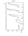
- Figure 2 represents the voltage profile obtained by using a positive electrode prepared from samples 1, 3, 5, 7 and 9 of formula Li 2 Ru 1-y Sn y O 3 which changes to Li x Ru 1- ySn y O 3 , x remaining lower than 2 after start of cycling.
- Figure 2 shows a stair-case curve during the first charge process which changes to a S-type curve during the first discharge and on subsequent charge/discharges, with therefore the amount of Li uptake and release depending upon the value of y.
- Li 2 RuO 3 (comparative sample 1) can practically uptake and release one Li per formula unit at an average voltage of 3.7 V with minimum polarisation owing to its metallic nature.
- the first charge displays a two steps (3.4 and 3.6 V) removal process which is also found on the second discharge and maintained on subsequent cycles. Replacing progressively Ru by Sn drastically changes the electrochemical properties of the pristine Li 2 RuO 3 phase.
- the charge curve shows a first plateau located near 3.6 V followed by a second plateau at 4.3 V whose amplitude varies with y.
- the following discharge profile as well as the subsequent charge/discharge profiles are totally different as they show a S-type profile.
- the cells using Ru-Sn based electrodes are cycling delivering an output voltage of 3.7 V as compared to 3.5 V for pure Li 2 RuO 3 hence leading to greater energy densities for the Ru-Sn compounds.
- Figure 3 shows a stair-case curve during the first charge process which changes to a S-type curve during the first discharge and on subsequent charge/discharges.
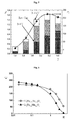
- Figure 4 represents the variation of discharge capacity D (mAh/g) of the cell, as a function of the number N of cycles, when using Li 2 Ru 0.75 Sn 0.25 O 3 , Li 2 Ru 0.5 Sn 0.5 O 3 and Li 2 Ru 0.5 Mn 0.5 O 3 as the cathode material, respectively. It shows that Li 2 Ru 0.75 Sn 0.25 O 3 and Li 2 Ru 0.5 Sn 0.5 O 3 provides a stable capacity over more than 60 cycles, whereas the capacity provided by Li 2 Ru 0.5 Mn 0.5 O 3 is not stable.
- Figure 5 represents a histogram showing the cycling characteristics of various samples of example 1. On figure 5 :
- Figure 6 represents the change of capacity C (mAh/g), when the charging/discharging rate R changes.
- the complex oxide Li 2 Ru 0.75 Sn 0.25 O 3 of the invention has a greater rate capability than the prior art complex oxide Li 2 Ru 0.5 Mn 0.5 O 3 .
- Li 2 Ru 0.75 Sn 0.25 O 3 has a great rate capability as nearly 200 mAh/g (90% of the initial capacity) can be tapped at a rate of 1C.
- Figure 7 represents the in situ XRD diagram for the sample Li 2 Ru 0.5 Sn 0.5 O 3 used as a cathode material in a Swagelok-typeTM cell similar to that used in Example 4, vs. Li + / Li 0 .
- the left hand vertical scale is the intensity I, in arbitrary units.
- the right hand vertical scale is the time T, in hours.
- 2 ⁇ CuK ⁇ is the diffraction angle.
- V is the voltage vs Li + /Li, in volts.
- the broad lines are the XRD patterns corresponding to the points represented 'a', 'b', 'c' and 'd'. These points and the XRD patterns show the change in the cycling behavior and XRD pattern. Region 'a' to 'b' corresponds to a typical solid solution insertion behavior with Ru 4+ / Ru 5+ redox process. From 'b' to 'c', the plateau region corresponds to oxygen evolution and Li extraction. Points 'c' to 'd' is the discharge curve.
- Figure 7 shows that oxidation process that occurs during a charge/discharge cycle at a rate of C/20 is highly reversible while preserving the crystallographic structure: the XRD of the pristine and fully discharged sample superimposed, with the only difference being a broadening of the peaks most likely associated to the creation of vacancies during the first oxidation which remains into the lattice on subsequent cycling.
- Figure 8 shows the voltage profile upon 1 st charge of the cell (left section) and the voltage profile upon 1 st discharge of the cell having the sodium salt electrolyte, and the subsequent charge (right section).
- a Na 2 Ru 0.5 Sn 0.5 O 3 sample was prepared by a solid state method, using the following starting products:
- the amount of the starting products corresponds to the stoichiometry, except for Na 2 CO 3 where a 10% excess is used to compensate for volatilization at high temperatures.
- the starting products in powder form were mixed using mortar and pestle for 20 minutes and then ball milled for 40 minutes.
- Heat treatment of the resultant mixture was carried out according to the following steps:
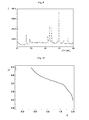
- Figure 9 represent the XRD diagram.
- the intensity I is in arbitrary unit, and 2 ⁇ CuK ⁇ is the diffraction angle.
- the ray marked ⁇ corresponds to a hydrated phase.
- a cell was assembled as in Example 4, using Na 2 Ru 0.5 Sn 0.5 O 3 as the cathode active material.
- the cell was cycled galvanostatically between 2 V and 4.6 V versus lithium at a charge rate of C/5 using a VMP3Z (Biologic) multi-channel potentiostat/galvanostat.
- the voltage profile for the first charge is represented on figure 10 . It shows removal of about 1.5 Na + .
Landscapes
- Chemical & Material Sciences (AREA)
- Inorganic Chemistry (AREA)
- Organic Chemistry (AREA)
- Chemical Kinetics & Catalysis (AREA)
- Electrochemistry (AREA)
- General Chemical & Material Sciences (AREA)
- Inorganic Compounds Of Heavy Metals (AREA)
- Secondary Cells (AREA)
- Battery Electrode And Active Subsutance (AREA)
Abstract
The present invention is related to a complex oxide.
The complex oxide has the crystallographic structure of Li2MO3 and formula A2M1-yM'yO3 where A is Li, Na or a mixture thereof, each of M and M' is a tetravalent metal selected from Ru, Ir, Pt, Sn and Ti, M is different from M', and 0<y<1
The complex oxide can be prepared by a solid state method, comprising mixing precursors of A, M and M' and applying a heat treatment.
The complex oxide is useful as the active electrode material of a lithium ion or a sodium ion battery.
Description
- The present invention related to an electrode material having a crystalline structure similar to that of Li2MnO3.
- Lithium Ion Batteries have been recognized as attractive energy storage systems not only for portable electronics but also for powering electric vehicles Performance of lithium ion batteries are governed mainly by the active material used as positive electrode. LiCoO2, LiMn2O4, LiFePO4 hitherto have been identified as suitable candidates for large scale applications. Still, the achievable specific capacity is lower than 200 mAhg-1 and a big improvement in the capacity values is needed immediately especially for the automobile applications. Manganese containing layered compounds have received much attention recently as they have been regarded as high voltage, high capacity cathode materials. Li2MnO3 has a rock salt type layered structure which can be depicted as Li[Li⅓Mn]O2 in the notion of LiMO2 layered compounds. In the rock salt type layered structure, the interslab octahedral sites are occupied by Li only, whereas within layers the octahedral sites are occupied by Li and Mn in 1:2 ratio [Strobel, P.; Lambertandron, B.; J. Solid State Chem. 1988, 75, 90-98]. The ideal capacity of Li2MnO3 alone can be as high as 460 mAh.g-1 which is much higher than that for LiCoO2 (270 mAh.g-1) and LiFePO4 (170 mAh.g-1). However Li2MnO3 is electrochemically inert as all the Mn in Li2MnO3 are in +4 oxidation state and so cannot be oxidized further. Similarly insertion of Li+ into Li2MnO3 is not possible because all the octahedral sites of the rocksalt structure are fully occupied and also no energetically favorable interstitial sites are available. It has been shown that Li2MnO3 can be made electrochemically active by acid leaching (to form Li2-xMnO3-x/2) [Rossouw, M.H.; Thackeray, M.M.; Mater. Res. Bull., 1991, 26, 463-473] or by low temperature preparations. However, during electrochemical cycling of the compounds obtained via said methods, the layer structure transforms to spinel phase. Further attempts to improve the electrochemical property of Li2MnO3 resulted in new series of composite cathode materials such as (1-y)Li2MnO3 - yLiMO2 (M = Co, Ni, Cr, etc) [Johnson, C.S. et al., Chem. Mater., 2008, 20, 6095], which exhibited higher capacity and excellent stability. Such composite materials showed specific capacity greater than 200 mAh.g-1. However, cathodes containing said compounds have complex structure and can be either described as [(1-x)LiMO2.xLi2MnO3, M=Ni,Co)] made of rocksalt Li2MnO3 and layered LiMO2 domains or as single phase layered oxides Li[Li0.2Ni0.15Mn0.48Co0.17]O2 having excess of Li within the metal oxide layers. Domain sizes of Li2MnO3 and so on were claimed to play different roles on the electrochemical performances of such materials. This is being created a large amount of animosity regarding patent issues on that topic.
- To attack this issue to depart both from the LiMO2 structure as well as from the nature of the 3d elements (Ni, Co and Mn) used, hence the study of the Li2Ru1-yMyO3 system. Such an approach find its origin in noting the richness of the rocksalt Li2MO3 as many representatives which can be either insulating (Mn,Sn) or metallic (Ru) so that solid solution should form, hence addressing the composite issue. Members of the Li2Ru1-yMnyO3 solid solution have in the past been studied for their magnetic properties and just recently for their electrochemical properties by Mori et al. [J. Power Sources, 2011, 196, 6934]. Mn is therefore a problematic redox center as it can be reduced to Mn+3, which besides being a Jahn Teller is partially soluble in Li-based electrolyte, hence our decision to study the Li2Ru1-ySnyO3 series as Sn(IV) is both not soluble and not easily reduced to Sn (II) (e.g, Sn(III) does not exist).
- Li2MnO3-Li2RuO3 solid solution compositions have high capacities but limited cycling performance owing to intrinsic issue linked to the partial reduction of Mn+4 causing formation of soluble Mn+3 which is detrimental to the long cycle life of an electrode. This phenomenon was previously experienced for the (1-y)Li2MnO3 - yLiMO2 (M = Co, Ni, Cr, etc) composites. The lithium ion battery technology still required an improved electrode material.
- The present invention provides an improved cathode material for a lithium ion battery, said material having a high reversible capacity and a long cycling life.
- One aspect of the invention is an active electrode material consisting of a complex oxide (I) having the crystallographic structure of Li2MO3 and formula A2M1-yM'yO3 where A is Li, Na or a mixture thereof, each of M and M' is a tetravalent metal selected from Ru, Ir, Pt, Sn and Ti, M is different from M', and 0<y<1.
- In an embodiment, the complex oxide is of formula A2Ru1-ySnyO3 where 0.1<y<0.8.
- Another aspect of the invention is a composite electrode material containing said complex oxide A2M1-yM'yO3 as the active electrode material, optionally an electronic conducting agent and optionally a binder. In an embodiment, the complex oxide is of formula A2Ru1-ySnyO3 where 0.1<y<0.8
- A further aspect of the invention is a method to prepare the active electrode material.
- An electrode active material of the invention is a complex oxide having the crystallographic structure of Li2MO3 and formula A2M1-yM'yO3 where A is Li, Na or a mixture thereof, each of M and M' is a tetravalent metal selected from Ru, Ir, Pt, Sn and Ti, M is different from M', and 0<y<1.
- In an embodiment, the complex oxide is of formula Li2Ru1-ySnyO3 having the crystallographic structure of Li2MnO3, 0.1<y<0.8.
- A compound of the invention can be prepared by a solid state method. The method comprises the steps of:
- ● Providing precursor powders
- ● Mixing precursor powders
- ● Heat treating the mixture of precursor powders.
- The Li precursor may be selected from Li2CO3, LiCOOCH3, and LiNO3. The Sn precursor may be selected from SnC2O4, SnO2, SnCOOCH3, and Sn(COOCH3)2. The Na precursor may be selected from Na2CO3, NaCOOCH3, and NaNO3. The Ru precursor may be selected from Ru metal powder, and RuO2. The Pt precursor may be selected from platinum black and platinum (IV) oxide. The Ir precursor may be selected from metallic Iridium powder and IrO2. The Ti precursor may be selected from TiO2, Ti powder and titanyl nitrate.
- The amounts of the precursors in the precursor mixture preferably correspond to the stoichiometric proportions. The lithium precursor or the sodium precursor may be used with a 10% excess in order to compensate for volatilization at high temperatures.
- In an embodiment, treatment comprises the following steps:
- heating the mixture to a temperature of 700°C to 800°C and maintaining the mixture at said temperature for a period of time from 6 to 12 hours (for example 6 hours at 800°C) ;
- heating the mixture to a temperature of 850°C to 900°C and maintaining the mixture at said temperature for a period of time from 12 to 16 hours (for example 12 hours at 900°C) ;
- heating the mixture to a temperature of 1050°C to 1100°C and maintaining the mixture at said temperature for a period of time from 6 to 12 hours (for example 12 hours at 1100°C).
- The precursors are mixed by conventional mixing methods such as ball milling, or precipitation / recrystallization so as to have homogeneous precursors.
- The heating is carried out at a rate of 2°C to 5°C/min (for example 2°C/min).
- The method may comprise a cooling step after each heating step, cooling being carried out at a rate of 2°C to 5°C/min (for example 2°C/min) to bring the mixture at the ambient temperature (about 20°C)
- The method may comprise a grinding step after each cooling step. Grinding may be carried out by ball milling.
- If the complex oxide (I) is Na2M1-yM'yO3, it is preferably transferred in an inert atmosphere to avoid reaction with moisture. The inert atmosphere may be Ar.
- A complex oxide (I) in which A is Li is useful as the cathode active material in a lithium ion battery. A complex oxide (I) in which A is Na is useful as the cathode active material in a sodium ion battery
- In one aspect, an electrode containing the complex oxide of the invention as the cathode active material is made of a composite electrode material on a current collector. The current collector may be a metal sheet, for instance Al or stainless steel. The composite electrode material contains the complex oxide of the invention, an electronic conducting agent, and optionally a polymer binder. The weight proportions are preferably:
Complex oxide 85 to 72 % Electronic conducting agent 10 to 20 % Binder 5 to 8 % - The invention is further explained by the following examples that illustrate the invention.
- Synthesis was carried out by a solid state method. The starting products used are:
- Li2CO3 (Sigma-Aldrich, purity 99.0 %),
- RuO2 (Sigma-Aldrich, purity 99.9%)
- SnC2O4 (Sigma-Aldrich, purity 98 %)
- The amount of the starting products corresponds to the stoichiometry, except for Li2CO3 where a 10% excess is used to compensate for volatilization at high temperatures.
- The starting products in powder form were mixed using mortar and pestle for 20 minutes and then ball milled for 40 minutes. Heat treatment of the resultant mixture was carried out according to the following steps:
- heating the mixture at a rate of 2°C/min up to 800°C and maintaining it at 800°C for 6 h;
- cooling the mixture to ambient temperature at a rate of 2°C/min;
- grinding the cooled mixture using high energy ball milling for 40 min;
- heating the mixture at a rate of 2°C/min up to 900°C and maintaining it at 900°C for 12 h;
- cooling the mixture to ambient temperature at a rate of 2°C/min;
- grinding the cooled mixture using high energy ball milling for 40 min;
- heating the mixture at a rate of 2°C/min up to 1100°C and maintaining it at 1100°C for 12 h;
- cooling the mixture to ambient temperature at a rate of 2°C/min;
- grinding the cooled mixture using high energy ball milling for 40 min.
- Nine samples were prepared according to this method, using different proportions of reactants to obtain final products with different y values.
- The following table summarizes the amounts of starting products for the 9 samples. The amounts are selected to produce about 3 g of Li2Ru1ySnyO3. Samples 2 to 7 are samples according to the invention.
Samples 1 and 9 are comparative samples.N° y Li2CO3 (g) RuO2 (g) SnC2O4 (g) 1 0 Li2RuO3 1.4964 2.4499 0 2 0.2 Li2Ru0.8Sn0.2O3 1.4647 1.9184 0.7451 3 0.25 Li2Ru0.75Sn0.0.25O3 1.4570 1.7890 0.9264 4 0.4 Li2Ru0.6Sn0.4O3 1.4343 1.4089 1.4592 5 0.5 Li2Ru0.5Sn0.5O3 1.4196 1.1620 1.8053 6 0.6 Li2Ru0.4Sn0.6O3 1.4051 0.9202 2.1443 7 0.75 Li2Ru0.25Sn0.75O3 1.3840 0.5665 2.6402 8 0.8 Li2Ru0.2Sn0.8O3 1.3771 0.4509 2.8022 9 1 Li2SnO3 1.3502 0 3.4342 - For comparison, Li2Ru0.5Mn0.5O3 was prepared according to the method of example 1, using the following starting products:
- 1.7431 g Li2CO3 (Sigma-Aldrich, purity 99.0 %),
- 1.4269 g RuO2 (Sigma-Aldrich, purity 99.9%)
- 1.2326 g MnCO3 (Sigma-Aldrich, purity 99.9% ).
- The Li2Ru1-ySnyO3 samples 3, 5 and 7 according to the invention and the
comparative samples 1 and 9 of Example 1 were characterized by XR diffraction. -
Figure 1 represents the XRD diagram for the various samples of Example 1. The intensity I is in arbitrary unit, and 2Θ CuKα is the diffraction angle.Figure 1 shows that there is a gradual shift of the peaks to lower angles when the amount of Sn grows. This confirms for each value of y, the sample is a complete solid solution. - Electrochemical tests were conducted using Swagelok-type™ cells assembled in an argon-filled glove box.
- The positive electrode is made of a composite electrode material on an Al collector. The composite electrode material was obtained by ball milling a mixture of 85 wt.% complex oxide and 15 wt.% Super-P Li Carbon (Timcal Belgium) as the conducting additive.
- The negative electrode was prepared by pressing a lithium metal film onto a thin stainless steel disc.
- The electrolyte used was 1M LiPF6 solution in a mixture of ethylene carbonate, propylene carbonate and dimethyl carbonate in 1:1:3 ratio by weight.
- Cells were made using various complex oxides and each cell was cycled galvanostatically between 2 V and 4.6 V versus lithium at a charge rate of C/5 using a VMP3Z (Biologic) multi-channel potentiostat/galvanostat.
- Each sample of table 1 was tested according to the above method. The voltage profiles were the same for each sample (each value of y).
-
Figure 2 represents the voltage profile obtained by using a positive electrode prepared fromsamples Figure 2 shows a stair-case curve during the first charge process which changes to a S-type curve during the first discharge and on subsequent charge/discharges, with therefore the amount of Li uptake and release depending upon the value of y. -
Figure 2 shows that Li2SnO3 (comparative sample 9) shows a very limited electrochemical capacity (x=0.2) with a 1 V polarization between charge and discharge due to a poor kinetic of the Li uptake-removal process most likely associated to its insulating nature. In contrast, Li2RuO3 (comparative sample 1) can practically uptake and release one Li per formula unit at an average voltage of 3.7 V with minimum polarisation owing to its metallic nature. The first charge displays a two steps (3.4 and 3.6 V) removal process which is also found on the second discharge and maintained on subsequent cycles. Replacing progressively Ru by Sn drastically changes the electrochemical properties of the pristine Li2RuO3 phase. For all the intermediate members, the charge curve shows a first plateau located near 3.6 V followed by a second plateau at 4.3 V whose amplitude varies with y. Unexpectedly, the following discharge profile as well as the subsequent charge/discharge profiles are totally different as they show a S-type profile. Afterwards the cells using Ru-Sn based electrodes are cycling delivering an output voltage of 3.7 V as compared to 3.5 V for pure Li2RuO3 hence leading to greater energy densities for the Ru-Sn compounds. -
Figure 3 represents the voltage profile obtained by using a positive electrode prepared from sample Li2Ru0.75Sn0.25O2 (y=0.25) the formula of which changes to LixRu0.75Sn0.25O2, x remaining lower than 2 after start of cycling.Figure 3 shows a stair-case curve during the first charge process which changes to a S-type curve during the first discharge and on subsequent charge/discharges. -
Figure 4 represents the variation of discharge capacity D (mAh/g) of the cell, as a function of the number N of cycles, when using Li2Ru0.75Sn0.25O3, Li2Ru0.5Sn0.5O3 and Li2Ru0.5Mn0.5O3 as the cathode material, respectively. It shows that Li2Ru0.75Sn0.25O3 and Li2Ru0.5Sn0.5O3 provides a stable capacity over more than 60 cycles, whereas the capacity provided by Li2Ru0.5Mn0.5O3 is not stable. -
Figure 5 represents a histogram showing the cycling characteristics of various samples of example 1. Onfigure 5 : - on the left hand vertical scale, N represents
- ● the number of lithium release at the end of the first charge of each cell at 4.6V (top or the upper section of each column), N 4.6V
- ● the overall amount of reversible Li (top of the middle section of each column), Rev. Cap., and
- ● the number of lithium release when charging the cells at a voltage of 4V (top of the lower section of each column) N 4V.
- on the right hand side scale, C represents the capacity in mAh/g. The capacity is shown by the dot at the top of each column
- on the horizontal scale, y identifies the compound Li2Ru1-ySnyO2 used as the starting product.
-
Figure 5 shows that the best performances are obtained for y=0.25 with the removal of 1.6 Li+ upon oxidation and the reversible uptake/removal of 1.3 Li+ leading to this compound a capacity of 230 mAh/g; Li2RuO3 has no reversible capacity; and Li2SnO3 has no conductivity. -
Figure 6 represents the change of capacity C (mAh/g), when the charging/discharging rate R changes. The complex oxide Li2Ru0.75Sn0.25O3 of the invention has a greater rate capability than the prior art complex oxide Li2Ru0.5Mn0.5O3. Li2Ru0.75Sn0.25O3 has a great rate capability as nearly 200 mAh/g (90% of the initial capacity) can be tapped at a rate of 1C. - On
figure 6 : - the curve defined by

- the curve defined by -o-o-o-o- corresponds to the compound Li2Ru0.75Sn0.25O3.
-
Figure 7 represents the in situ XRD diagram for the sample Li2Ru0.5Sn0.5O3 used as a cathode material in a Swagelok-type™ cell similar to that used in Example 4, vs. Li+/ Li0. The left hand vertical scale is the intensity I, in arbitrary units. The right hand vertical scale is the time T, in hours. On the left hand section of the horizontal scale, 2Θ CuKα is the diffraction angle. On the right hand section of the horizontal scale, V is the voltage vs Li+/Li, in volts. - The broad lines are the XRD patterns corresponding to the points represented 'a', 'b', 'c' and 'd'. These points and the XRD patterns show the change in the cycling behavior and XRD pattern. Region 'a' to 'b' corresponds to a typical solid solution insertion behavior with Ru4+/ Ru5+ redox process. From 'b' to 'c', the plateau region corresponds to oxygen evolution and Li extraction. Points 'c' to 'd' is the discharge curve.
-
Figure 7 shows that oxidation process that occurs during a charge/discharge cycle at a rate of C/20 is highly reversible while preserving the crystallographic structure: the XRD of the pristine and fully discharged sample superimposed, with the only difference being a broadening of the peaks most likely associated to the creation of vacancies during the first oxidation which remains into the lattice on subsequent cycling. - An electrochemical cell similar to those of Example 4, where the cathode active material is Li2Ru0.5Sn0.5O3 was charged to a voltage of 4.6 V vs Li+/Li0. The complex oxide changed to LixRu0.5Sn0.5O3, x<2. Then, the electrolyte was changed to a 1M NaClO4 solution in propylene carbonate and the negative electrode was changed to metallic sodium. The modified cell was then discharged, causing intercalation of Na+ into the complex oxide structure, thus forming a (LiNa)xRu0.5Sn0.5O3, x≤2.
-
Figure 8 shows the voltage profile upon 1st charge of the cell (left section) and the voltage profile upon 1st discharge of the cell having the sodium salt electrolyte, and the subsequent charge (right section). - A Na2Ru0.5Sn0.5O3 sample was prepared by a solid state method, using the following starting products:
- 1.7157 g Na2CO3 (Sigma-Aldrich, purity 99.0 %),
- 0.9791 g RuO2 (Sigma-Aldrich, purity 99.9%)
- 1.5211 g SnC2O4 (Sigma-Aldrich, purity 99.9% ).
- The amount of the starting products corresponds to the stoichiometry, except for Na2CO3 where a 10% excess is used to compensate for volatilization at high temperatures.
- The starting products in powder form were mixed using mortar and pestle for 20 minutes and then ball milled for 40 minutes. Heat treatment of the resultant mixture was carried out according to the following steps:
- heating the mixture at a rate of 2°C/min up to 800°C and maintaining it at 800°C for 6 h,
- Quenching the mixture to room temperature and transferring to Ar atmosphere to avoid reaction with moisture.
-
Figure 9 represent the XRD diagram. The intensity I is in arbitrary unit, and 2Θ CuKα is the diffraction angle. The ray marked ● corresponds to a hydrated phase. - A cell was assembled as in Example 4, using Na2Ru0.5Sn0.5O3 as the cathode active material. The cell was cycled galvanostatically between 2 V and 4.6 V versus lithium at a charge rate of C/5 using a VMP3Z (Biologic) multi-channel potentiostat/galvanostat. The voltage profile for the first charge is represented on
figure 10 . It shows removal of about 1.5 Na+.
Claims (10)
- An electrode active material comprising a complex oxide (I) having the crystallographic structure of Li2MO3 and formula A2M1-yM'yO3 where A is Li, Na or a mixture thereof, each of M and M' is a tetravalent metal selected from Ru, Ir, Pt, Sn and Ti, and M is different from M', 0<y<1.
- An electrode active material according to claim 1, where the complex oxide (I) is of formula A2Ru1-ySnyO3 and 0<y<1.
- An electrode material according to claim 1, characterized in that the complex oxide (I) is of formula Li2Ru1-ySnyO3, 0.1<y<0.8.
- A method for preparing a complex oxide according to claim 1, characterized in that said comprises the steps of :● Providing precursor powders● Mixing precursor powders● Heat treating the mixture of precursor powders.
- The method according to claim 3, characterized in that:- the Li precursor is selected from Li2CO3, LiCOOCH3, and LiNO3;- the Sn precursor is selected from SnC2O4, SnO2, SnCOOCH3, and Sn(COOCH3)2;- the sodium precursor is selected from Na2CO3, NaCOOCH3, and NaNO3;- the Ru precursor is selected from Ru metal powder, and RuO2;- the Pt precursor is selected from platinum black and platinum (IV) oxide;- the Ir precursor is selected from metallic Iridium powder and IrO2;- the Ti precursor is selected from TiO2, Ti powder and titanyl nitrate.
- The method according to claim 4, characterized in that the amounts of the precursors in the precursor mixture correspond to the stoichiometric proportions.
- The method according to claim 4, characterized in that the heat treatment comprises the following steps:- heating the mixture to a temperature of 700°C to 800°C and maintaining the mixture at said temperature for a period of time from 6 to 12 hours;- heating the mixture to a temperature of 850°C to 900°C and maintaining the mixture at said temperature for a period of time from 12 to 16 hours;- heating the mixture to a temperature of 1050°C to 1100°C and maintaining the mixture at said temperature for a period of time from 6 to 12 hours.
- The method according to claim 4, characterized in that heating is carried out at a rate of 2°C to 5°C/min.
- The method according to claim 7, characterized in that said method further comprises a cooling step after each heating step, cooling being carried out at a rate of 2°C to 5°C/min to bring the mixture at the ambient temperature.
- The method according to claim 7 to 10, characterized in that said method further comprises a grinding step after each cooling step.
Priority Applications (1)
| Application Number | Priority Date | Filing Date | Title |
|---|---|---|---|
| EP12197509.8A EP2744020A1 (en) | 2012-12-17 | 2012-12-17 | Complex oxide of alkali metal and tetravalent metal |
Applications Claiming Priority (1)
| Application Number | Priority Date | Filing Date | Title |
|---|---|---|---|
| EP12197509.8A EP2744020A1 (en) | 2012-12-17 | 2012-12-17 | Complex oxide of alkali metal and tetravalent metal |
Publications (1)
| Publication Number | Publication Date |
|---|---|
| EP2744020A1 true EP2744020A1 (en) | 2014-06-18 |
Family
ID=47428516
Family Applications (1)
| Application Number | Title | Priority Date | Filing Date |
|---|---|---|---|
| EP12197509.8A Withdrawn EP2744020A1 (en) | 2012-12-17 | 2012-12-17 | Complex oxide of alkali metal and tetravalent metal |
Country Status (1)
| Country | Link |
|---|---|
| EP (1) | EP2744020A1 (en) |
Cited By (2)
| Publication number | Priority date | Publication date | Assignee | Title |
|---|---|---|---|---|
| US9923198B2 (en) | 2014-12-30 | 2018-03-20 | Samsung Electronics Co., Ltd. | Cathode active material, cathode and lithium battery including the same, and method of preparing the cathode active material |
| CN113578308A (en) * | 2021-05-31 | 2021-11-02 | 重庆第二师范学院 | Photocatalyst Li2Sn0.7O3Preparation method and application thereof |
Citations (3)
| Publication number | Priority date | Publication date | Assignee | Title |
|---|---|---|---|---|
| US20060199078A1 (en) * | 2005-03-02 | 2006-09-07 | Matsushita Electric Industrial Co., Ltd. | Negative electrode for non-aqueous secondary battery |
| EP1708296A1 (en) * | 2005-03-31 | 2006-10-04 | Matsushita Electric Industrial Co., Ltd. | Negative electrode for non-aqueous secondary battery |
| JP2011181222A (en) * | 2010-02-26 | 2011-09-15 | Hitachi Ltd | Lithium ion battery |
-
2012
- 2012-12-17 EP EP12197509.8A patent/EP2744020A1/en not_active Withdrawn
Patent Citations (3)
| Publication number | Priority date | Publication date | Assignee | Title |
|---|---|---|---|---|
| US20060199078A1 (en) * | 2005-03-02 | 2006-09-07 | Matsushita Electric Industrial Co., Ltd. | Negative electrode for non-aqueous secondary battery |
| EP1708296A1 (en) * | 2005-03-31 | 2006-10-04 | Matsushita Electric Industrial Co., Ltd. | Negative electrode for non-aqueous secondary battery |
| JP2011181222A (en) * | 2010-02-26 | 2011-09-15 | Hitachi Ltd | Lithium ion battery |
Non-Patent Citations (4)
| Title |
|---|
| JOHNSON, C.S. ET AL., CHEM. MATER., vol. 20, 2008, pages 6095 |
| MORI ET AL., J. POWER SOURCES, vol. 196, 2011, pages 6934 |
| ROSSOUW, M.H.; THACKERAY, M.M., MATER. RES. BULL., vol. 26, 1991, pages 463 - 473 |
| STROBEL, P.; LAMBERTANDRON, B., J. SOLID STATE CHEM., vol. 75, 1988, pages 90 - 98 |
Cited By (2)
| Publication number | Priority date | Publication date | Assignee | Title |
|---|---|---|---|---|
| US9923198B2 (en) | 2014-12-30 | 2018-03-20 | Samsung Electronics Co., Ltd. | Cathode active material, cathode and lithium battery including the same, and method of preparing the cathode active material |
| CN113578308A (en) * | 2021-05-31 | 2021-11-02 | 重庆第二师范学院 | Photocatalyst Li2Sn0.7O3Preparation method and application thereof |
Similar Documents
| Publication | Publication Date | Title |
|---|---|---|
| US6677082B2 (en) | Lithium metal oxide electrodes for lithium cells and batteries | |
| US6680143B2 (en) | Lithium metal oxide electrodes for lithium cells and batteries | |
| US7358009B2 (en) | Layered electrodes for lithium cells and batteries | |
| Fey et al. | Preparation and electrochemical properties of high-voltage cathode materials, LiMyNi0. 5− yMn1. 5O4 (M= Fe, Cu, Al, Mg; y= 0.0–0.4) | |
| US7468223B2 (en) | Lithium metal oxide electrodes for lithium cells and batteries | |
| US9960417B2 (en) | Molybdenum oxides and uses thereof | |
| US7901658B2 (en) | Chemically stable solid lithium ion conductor | |
| KR101925105B1 (en) | Positive active material, method of preparing the same, and rechargeable lithium battery including the same | |
| KR20200141457A (en) | Doped layered oxide material containing O3/P2 mixed phase sodium | |
| EP2975678A1 (en) | Composite positive electrode active material, positive electrode including the same, and lithium battery including the positive electrode | |
| US8951668B2 (en) | Iron oxyfluoride electrodes for electrochemical energy storage | |
| JP2008511960A (en) | Manganese oxide composite electrode for lithium battery | |
| KR20250053071A (en) | Sodium layered oxide, uses thereof and methods of preparation thereof | |
| Zeng et al. | Effect of cationic and anionic substitutions on the electrochemical properties of LiNi0. 5Mn1. 5O4 spinel cathode materials | |
| Das et al. | Structural and electrochemical properties of nanocrystalline LixMn2O4 thin film cathodes (x= 1.0–1.4) | |
| EP3480874B1 (en) | Positive electrode material for secondary batteries, method for producing same, and lithium ion secondary battery | |
| US12334551B2 (en) | LMO cathode composition | |
| EP2630685B1 (en) | Process for the preparation of high voltage nano composite cathode (4.9v) for lithium ion batteries | |
| EP2744020A1 (en) | Complex oxide of alkali metal and tetravalent metal | |
| US20220367867A1 (en) | Lmo cathode compositions | |
| EP4614607A1 (en) | Method for manufacturing positive electrode active material for lithium-ion secondary battery | |
| US11884552B2 (en) | Fluorinated cation-disordered rocksalt materials and methods of making thereof | |
| Periasamy et al. | Electrochemical performance behavior of combustion-synthesized LiNi0. 5Mn0. 5O2 lithium-intercalation cathodes | |
| US20180351163A1 (en) | Stabilized lithium cobalt oxide spinel electrodes for lithium batteries | |
| KR20180025028A (en) | Manufacturing method of nickel rich cathod active material and nickel rich cathod active material made by the same |
Legal Events
| Date | Code | Title | Description |
|---|---|---|---|
| PUAI | Public reference made under article 153(3) epc to a published international application that has entered the european phase |
Free format text: ORIGINAL CODE: 0009012 |
|
| 17P | Request for examination filed |
Effective date: 20121217 |
|
| AK | Designated contracting states |
Kind code of ref document: A1 Designated state(s): AL AT BE BG CH CY CZ DE DK EE ES FI FR GB GR HR HU IE IS IT LI LT LU LV MC MK MT NL NO PL PT RO RS SE SI SK SM TR |
|
| AX | Request for extension of the european patent |
Extension state: BA ME |
|
| STAA | Information on the status of an ep patent application or granted ep patent |
Free format text: STATUS: THE APPLICATION IS DEEMED TO BE WITHDRAWN |
|
| 18D | Application deemed to be withdrawn |
Effective date: 20141219 |