EP2744017A2 - Secondary battery pack - Google Patents
Secondary battery pack Download PDFInfo
- Publication number
- EP2744017A2 EP2744017A2 EP12821536.5A EP12821536A EP2744017A2 EP 2744017 A2 EP2744017 A2 EP 2744017A2 EP 12821536 A EP12821536 A EP 12821536A EP 2744017 A2 EP2744017 A2 EP 2744017A2
- Authority
- EP
- European Patent Office
- Prior art keywords
- board
- battery cell
- pcm
- connection part
- pcm case
- Prior art date
- Legal status (The legal status is an assumption and is not a legal conclusion. Google has not performed a legal analysis and makes no representation as to the accuracy of the status listed.)
- Granted
Links
Images


Classifications
-
- H—ELECTRICITY
- H02—GENERATION; CONVERSION OR DISTRIBUTION OF ELECTRIC POWER
- H02H—EMERGENCY PROTECTIVE CIRCUIT ARRANGEMENTS
- H02H7/00—Emergency protective circuit arrangements specially adapted for specific types of electric machines or apparatus or for sectionalised protection of cable or line systems, and effecting automatic switching in the event of an undesired change from normal working conditions
- H02H7/18—Emergency protective circuit arrangements specially adapted for specific types of electric machines or apparatus or for sectionalised protection of cable or line systems, and effecting automatic switching in the event of an undesired change from normal working conditions for batteries; for accumulators
-
- H—ELECTRICITY
- H01—ELECTRIC ELEMENTS
- H01M—PROCESSES OR MEANS, e.g. BATTERIES, FOR THE DIRECT CONVERSION OF CHEMICAL ENERGY INTO ELECTRICAL ENERGY
- H01M50/00—Constructional details or processes of manufacture of the non-active parts of electrochemical cells other than fuel cells, e.g. hybrid cells
- H01M50/50—Current conducting connections for cells or batteries
- H01M50/572—Means for preventing undesired use or discharge
-
- H—ELECTRICITY
- H01—ELECTRIC ELEMENTS
- H01M—PROCESSES OR MEANS, e.g. BATTERIES, FOR THE DIRECT CONVERSION OF CHEMICAL ENERGY INTO ELECTRICAL ENERGY
- H01M10/00—Secondary cells; Manufacture thereof
- H01M10/04—Construction or manufacture in general
-
- H—ELECTRICITY
- H01—ELECTRIC ELEMENTS
- H01M—PROCESSES OR MEANS, e.g. BATTERIES, FOR THE DIRECT CONVERSION OF CHEMICAL ENERGY INTO ELECTRICAL ENERGY
- H01M10/00—Secondary cells; Manufacture thereof
- H01M10/04—Construction or manufacture in general
- H01M10/0436—Small-sized flat cells or batteries for portable equipment
-
- H—ELECTRICITY
- H01—ELECTRIC ELEMENTS
- H01M—PROCESSES OR MEANS, e.g. BATTERIES, FOR THE DIRECT CONVERSION OF CHEMICAL ENERGY INTO ELECTRICAL ENERGY
- H01M10/00—Secondary cells; Manufacture thereof
- H01M10/42—Methods or arrangements for servicing or maintenance of secondary cells or secondary half-cells
- H01M10/425—Structural combination with electronic components, e.g. electronic circuits integrated to the outside of the casing
-
- H—ELECTRICITY
- H01—ELECTRIC ELEMENTS
- H01M—PROCESSES OR MEANS, e.g. BATTERIES, FOR THE DIRECT CONVERSION OF CHEMICAL ENERGY INTO ELECTRICAL ENERGY
- H01M50/00—Constructional details or processes of manufacture of the non-active parts of electrochemical cells other than fuel cells, e.g. hybrid cells
- H01M50/10—Primary casings; Jackets or wrappings
- H01M50/116—Primary casings; Jackets or wrappings characterised by the material
- H01M50/117—Inorganic material
- H01M50/119—Metals
-
- H—ELECTRICITY
- H01—ELECTRIC ELEMENTS
- H01M—PROCESSES OR MEANS, e.g. BATTERIES, FOR THE DIRECT CONVERSION OF CHEMICAL ENERGY INTO ELECTRICAL ENERGY
- H01M50/00—Constructional details or processes of manufacture of the non-active parts of electrochemical cells other than fuel cells, e.g. hybrid cells
- H01M50/10—Primary casings; Jackets or wrappings
- H01M50/116—Primary casings; Jackets or wrappings characterised by the material
- H01M50/121—Organic material
-
- H—ELECTRICITY
- H01—ELECTRIC ELEMENTS
- H01M—PROCESSES OR MEANS, e.g. BATTERIES, FOR THE DIRECT CONVERSION OF CHEMICAL ENERGY INTO ELECTRICAL ENERGY
- H01M50/00—Constructional details or processes of manufacture of the non-active parts of electrochemical cells other than fuel cells, e.g. hybrid cells
- H01M50/10—Primary casings; Jackets or wrappings
- H01M50/116—Primary casings; Jackets or wrappings characterised by the material
- H01M50/124—Primary casings; Jackets or wrappings characterised by the material having a layered structure
-
- H—ELECTRICITY
- H01—ELECTRIC ELEMENTS
- H01M—PROCESSES OR MEANS, e.g. BATTERIES, FOR THE DIRECT CONVERSION OF CHEMICAL ENERGY INTO ELECTRICAL ENERGY
- H01M50/00—Constructional details or processes of manufacture of the non-active parts of electrochemical cells other than fuel cells, e.g. hybrid cells
- H01M50/10—Primary casings; Jackets or wrappings
- H01M50/147—Lids or covers
-
- H—ELECTRICITY
- H01—ELECTRIC ELEMENTS
- H01M—PROCESSES OR MEANS, e.g. BATTERIES, FOR THE DIRECT CONVERSION OF CHEMICAL ENERGY INTO ELECTRICAL ENERGY
- H01M50/00—Constructional details or processes of manufacture of the non-active parts of electrochemical cells other than fuel cells, e.g. hybrid cells
- H01M50/10—Primary casings; Jackets or wrappings
- H01M50/183—Sealing members
- H01M50/186—Sealing members characterised by the disposition of the sealing members
-
- H—ELECTRICITY
- H01—ELECTRIC ELEMENTS
- H01M—PROCESSES OR MEANS, e.g. BATTERIES, FOR THE DIRECT CONVERSION OF CHEMICAL ENERGY INTO ELECTRICAL ENERGY
- H01M50/00—Constructional details or processes of manufacture of the non-active parts of electrochemical cells other than fuel cells, e.g. hybrid cells
- H01M50/50—Current conducting connections for cells or batteries
- H01M50/528—Fixed electrical connections, i.e. not intended for disconnection
-
- H—ELECTRICITY
- H01—ELECTRIC ELEMENTS
- H01M—PROCESSES OR MEANS, e.g. BATTERIES, FOR THE DIRECT CONVERSION OF CHEMICAL ENERGY INTO ELECTRICAL ENERGY
- H01M50/00—Constructional details or processes of manufacture of the non-active parts of electrochemical cells other than fuel cells, e.g. hybrid cells
- H01M50/50—Current conducting connections for cells or batteries
- H01M50/543—Terminals
- H01M50/547—Terminals characterised by the disposition of the terminals on the cells
- H01M50/55—Terminals characterised by the disposition of the terminals on the cells on the same side of the cell
-
- H—ELECTRICITY
- H01—ELECTRIC ELEMENTS
- H01M—PROCESSES OR MEANS, e.g. BATTERIES, FOR THE DIRECT CONVERSION OF CHEMICAL ENERGY INTO ELECTRICAL ENERGY
- H01M50/00—Constructional details or processes of manufacture of the non-active parts of electrochemical cells other than fuel cells, e.g. hybrid cells
- H01M50/50—Current conducting connections for cells or batteries
- H01M50/543—Terminals
- H01M50/552—Terminals characterised by their shape
- H01M50/553—Terminals adapted for prismatic, pouch or rectangular cells
- H01M50/557—Plate-shaped terminals
-
- H—ELECTRICITY
- H01—ELECTRIC ELEMENTS
- H01M—PROCESSES OR MEANS, e.g. BATTERIES, FOR THE DIRECT CONVERSION OF CHEMICAL ENERGY INTO ELECTRICAL ENERGY
- H01M2220/00—Batteries for particular applications
- H01M2220/30—Batteries in portable systems, e.g. mobile phone, laptop
-
- Y—GENERAL TAGGING OF NEW TECHNOLOGICAL DEVELOPMENTS; GENERAL TAGGING OF CROSS-SECTIONAL TECHNOLOGIES SPANNING OVER SEVERAL SECTIONS OF THE IPC; TECHNICAL SUBJECTS COVERED BY FORMER USPC CROSS-REFERENCE ART COLLECTIONS [XRACs] AND DIGESTS
- Y02—TECHNOLOGIES OR APPLICATIONS FOR MITIGATION OR ADAPTATION AGAINST CLIMATE CHANGE
- Y02E—REDUCTION OF GREENHOUSE GAS [GHG] EMISSIONS, RELATED TO ENERGY GENERATION, TRANSMISSION OR DISTRIBUTION
- Y02E60/00—Enabling technologies; Technologies with a potential or indirect contribution to GHG emissions mitigation
- Y02E60/10—Energy storage using batteries
-
- Y—GENERAL TAGGING OF NEW TECHNOLOGICAL DEVELOPMENTS; GENERAL TAGGING OF CROSS-SECTIONAL TECHNOLOGIES SPANNING OVER SEVERAL SECTIONS OF THE IPC; TECHNICAL SUBJECTS COVERED BY FORMER USPC CROSS-REFERENCE ART COLLECTIONS [XRACs] AND DIGESTS
- Y02—TECHNOLOGIES OR APPLICATIONS FOR MITIGATION OR ADAPTATION AGAINST CLIMATE CHANGE
- Y02P—CLIMATE CHANGE MITIGATION TECHNOLOGIES IN THE PRODUCTION OR PROCESSING OF GOODS
- Y02P70/00—Climate change mitigation technologies in the production process for final industrial or consumer products
- Y02P70/50—Manufacturing or production processes characterised by the final manufactured product
-
- Y—GENERAL TAGGING OF NEW TECHNOLOGICAL DEVELOPMENTS; GENERAL TAGGING OF CROSS-SECTIONAL TECHNOLOGIES SPANNING OVER SEVERAL SECTIONS OF THE IPC; TECHNICAL SUBJECTS COVERED BY FORMER USPC CROSS-REFERENCE ART COLLECTIONS [XRACs] AND DIGESTS
- Y10—TECHNICAL SUBJECTS COVERED BY FORMER USPC
- Y10T—TECHNICAL SUBJECTS COVERED BY FORMER US CLASSIFICATION
- Y10T29/00—Metal working
- Y10T29/49—Method of mechanical manufacture
- Y10T29/49002—Electrical device making
- Y10T29/49108—Electric battery cell making
- Y10T29/4911—Electric battery cell making including sealing
Definitions
- the present invention relates to a secondary battery pack.
- the secondary batteries may be configured to have a detachable type structure in which the secondary batteries can be easily inserted into and removed from external devices or to have an embedded type structure in which the secondary batteries are embedded in the devices.
- secondary batteries used in the conventional mobile devices are configured to have a detachable type structure in which it is possible for a user to insert or remove a battery into or from each device.
- secondary batteries used in devices such as some mobile phones, tablet PCs, and smart pads, may be configured to have an embedded type structure.
- Lithium secondary batteries are widely used as such secondary batteries.
- Each of the secondary batteries includes an anode terminal and a cathode terminal electrically connected to a device, in which the secondary battery is mounted, and a safety element to effectively control an abnormal state, such as overcharge or overcurrent, of the secondary battery.
- the safety element may include a positive temperature coefficient (PTC) element, a protection circuit module (PCM), a fuse, and a thermal cutoff (TCO) element.
- PTC positive temperature coefficient
- PCM protection circuit module
- TCO thermal cutoff
- a safety element such as a PCM
- a battery cell including an anode terminal and a cathode terminal
- a conductive nickel plates by welding or soldering.
- the nickel plates are connected to the electrode terminals of the battery cell by welding or soldering
- a protection circuit board PCB
- a protective tape is attached to the other side of the double-sided tape
- electrode tabs of the PCB and the nickel plates are connected to each other by welding in a state in which the PCB is in tight contact with the battery cell.
- the PCM is connected to the battery cell to manufacture a battery pack.
- the PCM prefferably maintained in electrical connection with the electrode terminals of the battery cell and, at the same time, to be electrically isolated from other parts of the battery cell.
- insulative tapes are attached to various members, including the PCM.
- a sealed portion of a battery case is partially bent, and an insulative tape is attached thereon or a barcode is printed thereon. That is, the process is very complicated.
- a secondary battery pack includes a battery cell having an anode terminal and a cathode terminal formed at one face having a sealed surplus portion and a protection circuit module (PCM) electrically connected to the battery cell via the anode terminal and the cathode terminal.
- PCM protection circuit module
- the PCM may include a board having a protection circuit formed thereon, the board being provided with an anode terminal connection part and a cathode terminal connection part connected to the anode terminal and the cathode terminal, respectively, and a PCM case configured to receive the board through an open face thereof so that the PCM case surrounds the board.
- the board may be coupled to the anode terminal and the cathode terminal of the battery cell via the anode terminal connection part and the cathode terminal connection part, the board may be disposed in the PCM case in a state in which the board is parallel to the battery cell, and the PCM case, in which the board is disposed, may be mounted to the sealed surplus portion of the battery cell.
- the PCM may further include an electrically insulative lid to close the open face of the PCM case.
- the PCM case and the lid may be coupled to each other through an assembly type fastening structure.
- the PCM case may be provided with at least one fastening groove for coupling with the lid, and the lid may be provided with at least one fastening protrusion corresponding to the at least one fastening groove of the PCM case.
- the battery cell may be a plate-shaped battery cell, and the anode terminal and the cathode terminal may be plate-shaped conductive members.
- the board may further include an external input and output terminal.
- the external input and output terminal may be formed at the board at which the anode terminal connection part and the cathode terminal connection part are formed via an interconnection part.
- the external input and output terminal may be formed on the board at which the anode terminal connection part and the cathode terminal connection part are formed.
- the external input and output terminal may be formed at the other face of the board at which the anode terminal connection part and the cathode terminal connection part are formed.
- the PCM case may further include an opening, through which the external input and output terminal is drawn, formed at a face adjacent to the open face thereof.
- An example of the opening may be a slit type opening.
- the secondary battery pack may further include an insulative tape additionally attached to an electrode terminal exposure region of the sealed surplus portion.
- the insulative tape may be, for example, a double-sided tape.
- the secondary battery pack may further include an insulative tape additionally attached to at least one of outer faces of the PCM case.
- the battery cell may be configured to have a structure in which an electrode assembly, including cathodes, anodes, and separators respectively disposed between the cathodes and the anodes, is disposed in a battery case made of a laminate sheet including a metal layer and a resin layer in a sealed state.
- the board may be disposed in the PCM case in a state in which the board is parallel to the battery cell in an extension direction identical to an extension direction of the sealed surplus portion.
- the secondary battery pack may further include a nickel plate additionally mounted to one face of the cathode terminal, to which the cathode terminal connection part of the board is coupled, by ultrasonic welding.
- the secondary battery pack may further include a label to cover the battery cell.
- the label may be configured to have a structure to cover sealed outer circumferences of the battery cell.
- a protection circuit module includes a protection circuit board having an anode terminal connection part and a cathode terminal connection part connected to an anode terminal and a cathode terminal of a battery cell, respectively, and a PCM case configured to receive the protection circuit board through an open face thereof
- the protection circuit board may be coupled to the anode terminal and the cathode terminal of the battery cell via the anode terminal connection part and the cathode terminal connection part, the board may be disposed in the PCM case in a state in which the board is parallel to the battery cell, and the PCM case, in which the board is disposed, may be mounted to the sealed surplus portion of the battery cell.
- an electrically insulative lid may be mounted to the PCM case to close the open face of the PCM case.
- the PCM case and the lid may be coupled to each other through an assembly type fastening structure.
- the PCM case may be provided with at least one fastening groove for coupling with the lid, and the lid may be provided with at least one fastening protrusion corresponding to the at least one fastening groove of the PCM case.
- the PCM case may be provided with at least one fastening protrusion (for example, hook), and the lid may be provided with at least one fastening groove corresponding to the at least one fastening protrusion of the PCM case, or fastening protrusions and fastening grooves may be alternately formed at the PCM case and the lid. That is, the fastening structure to couple the PCM case and the lid is not particularly restricted so long as the PCM case and the lid can be coupled to each other.
- the PCM case may be configured to have a hollow box structure opened at one face thereof.
- the protection circuit board may further include an external input and output terminal coupled to the board at which the anode terminal connection part and the cathode terminal connection part are formed via an interconnection part.
- the PCM case may further include an opening, through which the interconnection part extends, formed at a face adjacent to the open face thereof. Also, the PCM case may include a slit type opening.
- a method of manufacturing a secondary battery pack includes a step of forming a battery cell configured to have a structure in which an electrode assembly, including cathodes, anodes, and separators respectively disposed between the cathodes and the anodes, is disposed in a battery case in a sealed state, one of sealed outer circumferences of the battery cell having a surplus portion, a step of receiving a board into a case opened at one face thereof in an extension direction identical to an extension direction of the sealed surplus portion in a state in which the board is parallel to the battery cell, a step of mounting the case to the sealed surplus portion of the battery cell, and a step of mounting an electrically insulative lid to the PCM case to close the open face of the PCM case.
- a secondary battery pack includes a battery cell having an anode terminal and a cathode terminal formed at one face having a sealed surplus portion and a protection circuit module (PCM) electrically connected to the battery cell via the anode terminal and the cathode terminal.
- PCM protection circuit module
- the PCM may include a board having a protection circuit formed thereon, the board being provided with an anode terminal connection part and a cathode terminal connection part connected to the anode terminal and the cathode terminal, respectively, and a PCM case configured to receive the board through an open face thereof so that the PCM case surrounds the board.
- the board may be coupled to the anode terminal and the cathode terminal of the battery cell via the anode terminal connection part and the cathode terminal connection part, the board may be disposed in the PCM case in a state in which the board is perpendicular to the battery cell, and the PCM case, in which the board is disposed, may be mounted to the sealed surplus portion of the battery cell, and the PCM may further include an electrically insulative lid to close the open face of the PCM case.
- the secondary battery pack according to the present invention is configured to have a structure in which the PCM, in which the PCB is disposed in the PCM case, is mounted to the sealed surplus portion of the battery cell. Consequently, it is possible to effectively protect the PCM and to greatly reduce the number of parts constituting the secondary battery pack, thereby greatly improving manufacturing efficiency, as compared with the conventional internal type secondary battery pack.
- the secondary battery pack according to the present invention is configured to have a structure in which the PCB is mounted in the PCM case in an insertion fashion. Consequently, it is possible to greatly reduce the number of parts constituting the secondary battery pack, thereby greatly improving manufacturing efficiency, thereby easily manufacturing the secondary battery pack, relatively reducing a defect rate, and configuring the secondary battery pack so that the secondary battery pack has no wrinkles formed at the outer face thereof, i.e. a neat and clean external appearance, as compared with the conventional internal type secondary battery pack in which the PCM is insulated using a tape.
- the secondary battery pack according to the present invention is configured to have a structure in which the PCB is mounted to the sealed surplus portion of the battery cell in a direction facing the upper end of the main body of the battery cell in a state in which the PCB is erected perpendicularly to the battery cell. Consequently, it is possible to reduce the length of the sealed surplus portion and to increase the capacity of the secondary battery pack per unit volume, as compared with the structure in which the PCB is mounted to the sealed surplus portion in parallel.
- a secondary battery pack includes a battery cell having four sealed outer circumferences and a safety element mounted to a sealed outer circumference having a surplus portion, which is one of the outer circumferences.
- a safety element may include a first safety element and a second safety element.
- the first safety element may be a protection circuit
- the second safety element may be a positive temperature coefficient (PTC) element, a fuse, or a thermal cutoff (TCO) element.
- the second safety element may be mounted in a protection circuit module (PCM) in the form of a part.
- PCM protection circuit module
- the safety element according to the embodiment of the present invention may be a PCM.
- the PCM may include a protection circuit board and a case, in which the protection circuit board is disposed.
- the PCM may also include an electrically insulative lid to close an open face of the case.
- a PCM will be described as being adopted as the safety element, and the PCM will be described as including a protection circuit board (PCB) in this specification, to which, however, the safety element according to the embodiment of the present invention is not limited.
- PCB protection circuit board
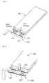
- FIG. 1 typically shows an exploded perspective view of a secondary battery pack according to an embodiment of the present invention.
- a secondary battery pack 700 may include an anode terminal 120, a cathode terminal 110, a battery cell 100, a PCM 500, and a label 400.
- a battery cell 100 according to an embodiment of the present invention is a pouch-shaped battery cell configured so that an electrode assembly of a cathode/separator/anode structure is disposed in a battery case made of a laminate sheet including a metal layer and a resin layer in a sealed state, to which, however, the battery cell according to the embodiment of the present invention is not limited.
- the battery cell 100 includes a sealed surplus portion 130 formed at one face thereof and an anode terminal 120 and a cathode terminal 110 exposed to the sealed surplus portion 130.
- the term 'face' used in this specification indicates an arbitrary face of a tetrahedron with four faces, and is understood as including a side, a section, or an end.
- a sealed portion having a surplus space formed at one of the sealed outer circumferences formed when an electrode assembly is disposed in a battery case made of a laminate sheet in a sealed state is referred to as a sealed surplus portion 130.
- the sealed surplus portion may be replaced by terms, such as a thermal welded surplus portion and a sealed terrace, as long as the specified terms have the same meaning as the sealed surplus portion.
- An electrically insulative lid 600 is configured to have a structure to close an open face of a PCM case 300.
- the electrically insulative lid 600 is provided with hooks 610 corresponding to fastening grooves 320 of the PCM case 300, and the PCM case 300 is provided with fastening grooves 320 corresponding to the hooks 610 of the electrically insulative lid 600. Consequently, the PCM case 300 and the electrically insulative lid 600 may be coupled to each other through an assembly type fastening structure.
- An anode terminal 120 and a cathode terminal 110 are plate-shaped conductive members.
- the anode terminal 120 and the cathode terminal 110 are electrically connected to a PCB 200 of a PCM 500, which will hereinafter be described.
- a PCM 500 may include a PCB 200 having a protection circuit, an electrically insulative PCM case 300, in which the PCB 200 is disposed, and an external input and output terminal 210.
- the PCB 200 is a board including a protection circuit.
- the PCB may be referred to as a protection circuit board or simply a board.
- the PCB 200 may further include an anode terminal connection part 220 connected to the anode terminal 120 of the battery cell 100 and a cathode terminal connection part 230 connected to the cathode terminal 110 of the battery cell 100 on the board in addition to the protection circuit to control overcharge, overdischarge, and overcurrent of the battery.
- the PCB 200 may further include an external input and output terminal 210 connected to the board via an interconnection part 211 connected to one end of the board, as shown in FIG. 1 .
- An external input and output terminal 210 is not particularly restricted so long as the external input and output terminal can be electrically connected to the PCB 200 to supply current from an external device, such as a charger, to the battery cell 100 or to supply current from the battery cell 100 to an external device, such as a mobile phone, an MP3 player, etc.
- the external input and output terminal 210 may be configured to have a plate structure having a connector 212 mounted to one end thereof
- the external input and output terminal may be formed on the board on which the anode terminal connection part and the cathode terminal connection part are formed without being connected to the PCB 200 via the interconnection part.
- a secondary battery pack with the above-stated construction is shown in FIG. 11 .
- openings are formed at a region of a PCM case 420 (see FIG. 11 ), in which the PCB is disposed, corresponding to an external input and output terminal 430 (see FIG. 11 ).
- the external input and output terminal may be electrically connected to an external device through the openings.
- An anode terminal connection part 220 may include a part coupled to the PCB 200 and an extension part that can be bent when the anode terminal connection part 220 is connected to the anode terminal 120 of the battery cell 100.
- a cathode terminal connection part 230 may include a part coupled to the PCB 200 and an extension part that can be bent when the cathode terminal connection part 230 is connected to the cathode terminal 110 of the battery cell 100.
- the external input and output terminal 210 is configured to have a plate structure having a connector 212 mounted to one end thereof, to which, however, the external input and output terminal 210 is not limited. Also, as shown in FIG. 1 , the external input and output terminal 210 is configured to face in a direction opposite to a direction in which the anode terminal connection part 220 and the cathode terminal connection part 230 face, which, however, is only an example. According to another embodiment of the present invention, the external input and output terminal 210 may be configured to face in the same direction as a direction in which the anode terminal connection part 220 and the cathode terminal connection part 230 face. Also, the external input and output terminal may be located at the cathode terminal connection part side.
- a PCM case 300 is configured to have a hollow box structure opened at one face thereof so that the PCB 200 can be mounted in the PCM case 300 through the open face. Consequently, dimensional stability of the PCM case 300 is high, and it is possible to greatly reduce mounting time and process.
- the mounting time means time required for an assembly process of placing the PCB 200 in the PCM case 300 and assembling the PCB 200 with the PCM case 300. Reduction of the mounting time means reduction of time required for the assembly process, and therefore, it is possible to greatly simplify the process.
- the PCM case 300 may have a size sufficient to receive and surround the PCB 200 mounted on the sealed surplus portion 130 of the battery cell 100.
- an opening, through which the external input and output terminal 210 is exposed may be formed at a face of the PCM case 300 adjacent to the open face.
- a slit type opening 310 may be formed at the PCM case.
- a secondary battery pack according to another embodiment of the present invention may be configured so that a safety element is further mounted between at least one of the electrode terminals, i.e. the anode terminal and/or the cathode terminal, of the battery cell and the PCB.
- the safety element may be disposed between, for example, the anode terminal of the battery and the PCB.
- the safety element is mounted in the PCM case together with the PCB so that the structural stability of the safety element is secured.
- the safety element is a member which interrupts current when the temperature of the battery cell is increased to secure safety.
- the safety element may be a PTC element, the resistance of which increases as the temperature of the battery cell is increased, or a fuse, which is broken when the temperature of the battery cell is increased.
- the safety element is not limited to the PTC element and the fuse.
- FIGS. 2 to 10 are various perspective views of a secondary battery pack illustrating a method of manufacturing the secondary battery pack.
- a surplus portion i.e. a sealed surplus portion 130
- the sealed surplus portion 130 has a size sufficient to receive a PCM 500, in which a PCB 200 is coupled with a PCM case 300, and the size of the PCM case 300 may be greater or less than that of the sealed surplus portion 130.
- the size of the PCM case 300 may be properly adjusted based on the capacity and shape of the battery cell.
- a nickel plate 140 may be coupled to a portion of the cathode terminal 110, for example, by ultrasonic welding.
- the nickel plate 140 is mounted to the cathode terminal 110, it is possible to prevent deterioration of weldability between the cathode terminal, made of aluminum, of the battery cell and a PCB cathode terminal connection part made of nickel due to different properties.
- an additional safety element such as a PTC element, may be selectively mounted between the anode terminal 120 and an anode terminal connection part 220 to secure stability.
- the anode terminal connection part 220 and a cathode terminal connection part 230 formed at the PCB 200 are welded to the anode terminal 120 and the cathode terminal 110 of the battery cell 100, respectively, for example, by spot welding.
- the cathode terminal connection part 230 is welded to the nickel plate 140.
- the anode terminal connection part 220 and the cathode terminal connection part 230 each include a part coupled to the PCB 200 and a bendable extension part as described above, the anode terminal connection part 220 and the cathode terminal connection part 230 of the PCB 200 may be coupled to the anode terminal 120 and the cathode terminal 110 of the battery cell 100, respectively, by welding so that the PCB 200 is opposite to one face of the battery cell 100 at which the sealed surplus portion 130 is formed, as can be seen from FIG. 3 .
- an adhesive tape 160 serving as an insulation tape, may be attached to an electrode terminal exposure region of the sealed surplus portion 130 of the main body of the battery cell 100.
- the insulation tape is further attached to the electrode terminal exposure region of the sealed surplus portion 130 as described above, it is possible to more effectively improve insulativity of the electrode terminal exposure region.
- the insulation tape is a double-sided tape
- the double-side tape provides coupling force between the PCM case and the sealed surplus portion when the PCM case is mounted to the PCB, thereby further improving structural stability.
- the PCB 200 connected to the battery cell 100 via the anode terminal connection part and the cathode terminal connection part, may be disposed in the PCM case in a state in which the PCB 200 is parallel to the battery cell 100, and may be mounted to the sealed surplus portion of the battery cell 100.
- the state in which the PCB 200 is parallel to the battery cell 100 may be, for example, a state in which the anode terminal connection part 220 and the cathode terminal connection part 230, connected to the anode terminal and the cathode terminal of the battery cell, are disposed so as to face upward as shown in FIG. 4 . In this case, as shown in FIG.
- the PCB 200 may be spaced apart from the end of the battery cell at which the sealed surplus portion is formed by the connection length between the anode terminal and the anode terminal connection part and between the cathode terminal and the cathode terminal connection part in the longitudinal direction so that the PCB 200 is parallel to the sealed surplus portion.
- the face of the PCB 200 at which the anode terminal connection part 220 and the cathode terminal connection part 230 are located faces upward with the result that two widest ones of the four faces constituting the external appearance of the PCB 200 face upward and downward.
- the two widest ones of the four faces constituting the external appearance of the PCB 200 face upward and downward, the two widest faces of the PCB 200 and two widest faces of the battery cell 100 are disposed so as to face in the same directions. Consequently, that the PCB 200 is disposed in parallel to the battery cell 100 may be understood as including the above-mentioned positional relationship.
- the board may be disposed in the PCM case in a state in which the board is parallel to the battery cell in an extension direction identical to an extension direction of the sealed surplus portion.
- the PCM case 300 is opened at one face thereof so that the PCM case 300 receives the PCB 200 through the open face.
- an opening e.g. a slit type opening 310, may be formed at one face of the PCM case 300 corresponding to the interconnection part 211 of the PCB 200 so that the external input and output terminal 210 is exposed outside. Since the interconnection part 211 of the PCB 200 extends through the slit type opening 310, the external input and output terminal 210 connected to the interconnection part 211 is exposed outside.
- the PCM case may be mounted to the battery cell in a state in which the opening faces upward as shown in FIG. 1 or in an arrow direction as shown in FIG. 5 . Also, the PCM case may be mounted to the battery cell in a state in which the board is perpendicular to the battery cell as well as in a state in which the board is parallel to the battery cell, as previously described.
- the anode terminal 120 and the cathode terminal 110 are bent toward one face of the battery cell at which the sealed surplus portion 130 is formed so that the PCM case 300 is mounted to the sealed surplus portion 130 of the battery cell 100.
- the PCB 200 When the PCB 200 is mounted to the sealed surplus portion 130 formed at one face of the battery cell 100 as described above, the PCB 200 is mounted perpendicularly to the sealed surplus portion 130. In a case in which it is difficult for the sealed surplus portion 130 to have a sufficient size, therefore, the size of the PCB 200 may be reduced.
- the PCM case 300 in which the board is disposed, is opened at one face thereof.
- the open face of the PCM case 300 may be closed by the electrically insulative lid 600.
- the electrically insulative lid 600 is provided with the hooks 610 corresponding to the fastening grooves 320 of the PCM case 300, and the PCM case 300 is provided with the fastening grooves 320 corresponding to the hooks 610 of the electrically insulative lid 600. Consequently, the PCM case 300 and the electrically insulative lid 600 may be coupled to each other through an assembly type fastening structure.
- the position and shape of the fastening grooves and fastening protrusions are not particularly restricted so long as the PCM case and the lid are coupled to each other by the fastening grooves and the fastening protrusions.
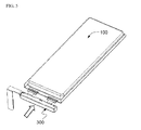
- FIG. 9 is a view showing a state in which a label 400 covers the PCM case 300 and the battery cell 100 in a state in which the PCB 200 mounted to sealed surplus portion 130 of the battery cell 100 is disposed in the PCM case 300.
- the label 400 according to the present invention may be configured to cover the outer faces of the PCM case 300 and the sealed outer circumferences of the battery cell 100 (see arrow directions in FIG. 9 ) so that the external input and output terminal can be exposed outside.
- the label 500 may be attached to cover the outer faces of the PCM 500 and the sealed outer circumferences of the battery cell 100 excluding the external input and output terminal 210 exposed outside.
- the label 400 is attached to the battery cell, it is possible to stably fix the sealed outer circumferences of the battery cell to the main body of the battery cell while maintaining the overall insulation state, thereby more stably securing the electrical connection state between the electrode terminals of the battery cell and the PCB.
- FIG. 11 is a perspective view of a secondary battery pack according to another embodiment of the present invention configured so that an external input and output terminal is mounted to a PCB.
- a secondary battery pack 800 is configured to have a structure in which an external input and output terminal 430 is formed at one face of the PCB (not shown) so that the external input and output terminal 430 is exposed outside through a PCM case 420.
- the secondary battery pack according to the present invention is configured so that the PCM 500, in which the protection circuit board electrically connected to the cathode terminal and the anode terminal of the battery cell is disposed in the case, is mounted to the sealed surplus portion formed at one face of the battery cell. Consequently, it is possible to effectively protect the PCM and to greatly reduce the number of parts constituting the secondary battery pack, thereby greatly improving manufacturing efficiency, as compared with the conventional secondary battery pack.
- the secondary battery pack according to the present invention is configured so that the protection circuit board is disposed in the electrically insulative case. Consequently, it is possible to protect and insulate the PCM including the protection circuit board. Also, it is possible to easily prevent the electrode terminals from being exposed outside without insulation of the electrode terminals through the use of additional members.
- the secondary battery pack according to the present invention is configured so that the protection circuit board is mounted in the case. Consequently, it is possible to easily manufacture the secondary battery pack, to relatively reduce a defect rate, and to configure the secondary battery pack so that the secondary battery pack has no wrinkles formed at the outer face thereof, i.e. a neat and clean external appearance, as compared with the conventional secondary battery pack in which the PCM is insulated using a tape.
- the secondary battery pack according to the present invention is configured so that the protection circuit board is mounted to the sealed surplus portion formed at one face of the battery cell. Consequently, it is possible to reduce the length of the sealed surplus portion and to increase the capacity of the battery pack per unit volume, as compared with the conventional secondary battery pack.
- connection members and the PCM are coupled, and an insulative tape is attached at each step, to the PCM assembly is mounted to the battery cell, as previously described. That is, the PCM assembly is mounted to the battery cell using a plurality of parts with the result that a plurality of processes is required, and structural stability as well as mechanical strength is low.
- the protection circuit module according to the present invention is configured to have a structure in which the protection circuit board is mounted in the case, and therefore, it is possible to improve structural stability of the battery pack, to greatly simplify the process of manufacturing the battery pack, to secure excellent insulativity, and to maximize the capacity of the battery cell in the battery pack having the same standard as the conventional battery pack.
- the protection circuit board is electrically connected to the electrode terminals, the electrode terminals are bent, and then the protection circuit board is mounted in the case with the result that no exposed region is formed during the bending process, and therefore, an additional insulative member is not required.
Landscapes
- Chemical & Material Sciences (AREA)
- Chemical Kinetics & Catalysis (AREA)
- Electrochemistry (AREA)
- General Chemical & Material Sciences (AREA)
- Engineering & Computer Science (AREA)
- Manufacturing & Machinery (AREA)
- Microelectronics & Electronic Packaging (AREA)
- Inorganic Chemistry (AREA)
- Battery Mounting, Suspending (AREA)
- Connection Of Batteries Or Terminals (AREA)
- Sealing Battery Cases Or Jackets (AREA)
Abstract
Description
- The present invention relates to a secondary battery pack.
- As mobile devices have been increasingly developed, and the demand for such mobile devices has increased, the demand for secondary batteries has also sharply increased. Among such secondary batteries is a lithium secondary battery exhibiting high energy density and operating voltage and excellent preservation and service-life characteristics, which has been widely used as an energy source for various electronic products as well as various kinds of mobile devices.
- Depending upon kinds of devices in which secondary batteries are used, the secondary batteries may be configured to have a detachable type structure in which the secondary batteries can be easily inserted into and removed from external devices or to have an embedded type structure in which the secondary batteries are embedded in the devices. For example, secondary batteries used in the conventional mobile devices are configured to have a detachable type structure in which it is possible for a user to insert or remove a battery into or from each device. On the other hand, secondary batteries used in devices, such as some mobile phones, tablet PCs, and smart pads, may be configured to have an embedded type structure.
- Lithium secondary batteries are widely used as such secondary batteries. Each of the secondary batteries includes an anode terminal and a cathode terminal electrically connected to a device, in which the secondary battery is mounted, and a safety element to effectively control an abnormal state, such as overcharge or overcurrent, of the secondary battery. Examples of the safety element may include a positive temperature coefficient (PTC) element, a protection circuit module (PCM), a fuse, and a thermal cutoff (TCO) element.
- Generally, a safety element, such as a PCM, is connected to a battery cell, including an anode terminal and a cathode terminal, via a conductive nickel plates by welding or soldering. For example, the nickel plates are connected to the electrode terminals of the battery cell by welding or soldering, a protection circuit board (PCB) is attached to one side of a double-sided tape, a protective tape is attached to the other side of the double-sided tape, and electrode tabs of the PCB and the nickel plates are connected to each other by welding in a state in which the PCB is in tight contact with the battery cell. In this way, the PCM is connected to the battery cell to manufacture a battery pack.
- It is required for the PCM to be maintained in electrical connection with the electrode terminals of the battery cell and, at the same time, to be electrically isolated from other parts of the battery cell. To this end, insulative tapes are attached to various members, including the PCM. In addition, a sealed portion of a battery case is partially bent, and an insulative tape is attached thereon or a barcode is printed thereon. That is, the process is very complicated.
- Since a plurality of insulative tapes or parts is required to achieve safe connection between the safety element and the battery cell as described above, a battery pack assembly process is complicated, and manufacturing cost is increased. Also, when external impact is applied to a battery pack, the PCM may be damaged or dimensional stability may be greatly lowered due to the use of the insulative tapes, which exhibit low mechanical strength.
- It is an object of the present invention to provide a secondary battery pack that is capable of covering a protection circuit board of a secondary battery cell using an electrically insulative case, thereby protecting the protection circuit board from external impact, insulating the protection circuit board, and preventing electrode terminals of the secondary battery cell from being exposed outside.
- It is another object of the present invention to provide a secondary battery pack that is capable of reducing the number of parts necessary to constitute the battery pack, thereby simplify an assembly process and exhibiting excellent structural stability.
- It is another object of the present invention to provide a secondary battery pack configured to have a structure in which a protection circuit module including a protection circuit board and a case, in which the protection circuit board is disposed, is mounted to an outer circumference of a battery cell, thereby providing maximum capacity in the same standard.
- It is a further object of the present invention to provide a protection circuit module that is capable of a protection circuit module that is capable of protecting a safety element from external impact, exhibiting dimensional stability, and preventing wrinkles from being formed at an outer face of a battery pack.
- A secondary battery pack according to an embodiment of the present invention includes a battery cell having an anode terminal and a cathode terminal formed at one face having a sealed surplus portion and a protection circuit module (PCM) electrically connected to the battery cell via the anode terminal and the cathode terminal.
- In this embodiment, the PCM may include a board having a protection circuit formed thereon, the board being provided with an anode terminal connection part and a cathode terminal connection part connected to the anode terminal and the cathode terminal, respectively, and a PCM case configured to receive the board through an open face thereof so that the PCM case surrounds the board.
- In this embodiment, the board may be coupled to the anode terminal and the cathode terminal of the battery cell via the anode terminal connection part and the cathode terminal connection part, the board may be disposed in the PCM case in a state in which the board is parallel to the battery cell, and the PCM case, in which the board is disposed, may be mounted to the sealed surplus portion of the battery cell.
- In this embodiment, the PCM may further include an electrically insulative lid to close the open face of the PCM case.
- In this embodiment, the PCM case and the lid may be coupled to each other through an assembly type fastening structure. The PCM case may be provided with at least one fastening groove for coupling with the lid, and the lid may be provided with at least one fastening protrusion corresponding to the at least one fastening groove of the PCM case.
- In this embodiment, the battery cell may be a plate-shaped battery cell, and the anode terminal and the cathode terminal may be plate-shaped conductive members.
- In this embodiment, the board may further include an external input and output terminal. The external input and output terminal may be formed at the board at which the anode terminal connection part and the cathode terminal connection part are formed via an interconnection part.
- Also, the external input and output terminal may be formed on the board at which the anode terminal connection part and the cathode terminal connection part are formed.
- In this embodiment, the external input and output terminal may be formed at the other face of the board at which the anode terminal connection part and the cathode terminal connection part are formed.
- In this embodiment, the PCM case may further include an opening, through which the external input and output terminal is drawn, formed at a face adjacent to the open face thereof. An example of the opening may be a slit type opening.
- In this embodiment, the secondary battery pack may further include an insulative tape additionally attached to an electrode terminal exposure region of the sealed surplus portion. The insulative tape may be, for example, a double-sided tape.
- In this embodiment, the secondary battery pack may further include an insulative tape additionally attached to at least one of outer faces of the PCM case.
- In this embodiment, the battery cell may be configured to have a structure in which an electrode assembly, including cathodes, anodes, and separators respectively disposed between the cathodes and the anodes, is disposed in a battery case made of a laminate sheet including a metal layer and a resin layer in a sealed state.
- In this embodiment, the board may be disposed in the PCM case in a state in which the board is parallel to the battery cell in an extension direction identical to an extension direction of the sealed surplus portion.
- In this embodiment, the secondary battery pack may further include a nickel plate additionally mounted to one face of the cathode terminal, to which the cathode terminal connection part of the board is coupled, by ultrasonic welding.
- In this embodiment, the secondary battery pack may further include a label to cover the battery cell. The label may be configured to have a structure to cover sealed outer circumferences of the battery cell.
- A protection circuit module according to another embodiment of the present invention includes a protection circuit board having an anode terminal connection part and a cathode terminal connection part connected to an anode terminal and a cathode terminal of a battery cell, respectively, and a PCM case configured to receive the protection circuit board through an open face thereof
- In the protection circuit module according to this embodiment, the protection circuit board may be coupled to the anode terminal and the cathode terminal of the battery cell via the anode terminal connection part and the cathode terminal connection part, the board may be disposed in the PCM case in a state in which the board is parallel to the battery cell, and the PCM case, in which the board is disposed, may be mounted to the sealed surplus portion of the battery cell.
- In the protection circuit module according to this embodiment, an electrically insulative lid may be mounted to the PCM case to close the open face of the PCM case.
- In the protection circuit module according to this embodiment, the PCM case and the lid may be coupled to each other through an assembly type fastening structure. The PCM case may be provided with at least one fastening groove for coupling with the lid, and the lid may be provided with at least one fastening protrusion corresponding to the at least one fastening groove of the PCM case. Alternatively, a person having ordinary skill in the art to which the present invention pertains will appreciate that the PCM case may be provided with at least one fastening protrusion (for example, hook), and the lid may be provided with at least one fastening groove corresponding to the at least one fastening protrusion of the PCM case, or fastening protrusions and fastening grooves may be alternately formed at the PCM case and the lid. That is, the fastening structure to couple the PCM case and the lid is not particularly restricted so long as the PCM case and the lid can be coupled to each other.
- In the protection circuit module according to this embodiment, the PCM case may be configured to have a hollow box structure opened at one face thereof.
- In the protection circuit module according to this embodiment, the protection circuit board may further include an external input and output terminal coupled to the board at which the anode terminal connection part and the cathode terminal connection part are formed via an interconnection part. The PCM case may further include an opening, through which the interconnection part extends, formed at a face adjacent to the open face thereof. Also, the PCM case may include a slit type opening.
- A method of manufacturing a secondary battery pack according to another embodiment of the present invention includes a step of forming a battery cell configured to have a structure in which an electrode assembly, including cathodes, anodes, and separators respectively disposed between the cathodes and the anodes, is disposed in a battery case in a sealed state, one of sealed outer circumferences of the battery cell having a surplus portion, a step of receiving a board into a case opened at one face thereof in an extension direction identical to an extension direction of the sealed surplus portion in a state in which the board is parallel to the battery cell, a step of mounting the case to the sealed surplus portion of the battery cell, and a step of mounting an electrically insulative lid to the PCM case to close the open face of the PCM case.
- A secondary battery pack according to a further embodiment of the present invention includes a battery cell having an anode terminal and a cathode terminal formed at one face having a sealed surplus portion and a protection circuit module (PCM) electrically connected to the battery cell via the anode terminal and the cathode terminal.
- In this embodiment, the PCM may include a board having a protection circuit formed thereon, the board being provided with an anode terminal connection part and a cathode terminal connection part connected to the anode terminal and the cathode terminal, respectively, and a PCM case configured to receive the board through an open face thereof so that the PCM case surrounds the board.
- In this embodiment, the board may be coupled to the anode terminal and the cathode terminal of the battery cell via the anode terminal connection part and the cathode terminal connection part, the board may be disposed in the PCM case in a state in which the board is perpendicular to the battery cell, and the PCM case, in which the board is disposed, may be mounted to the sealed surplus portion of the battery cell, and the PCM may further include an electrically insulative lid to close the open face of the PCM case.
- The secondary battery pack according to the present invention is configured to have a structure in which the PCM, in which the PCB is disposed in the PCM case, is mounted to the sealed surplus portion of the battery cell. Consequently, it is possible to effectively protect the PCM and to greatly reduce the number of parts constituting the secondary battery pack, thereby greatly improving manufacturing efficiency, as compared with the conventional internal type secondary battery pack.
- Also, the secondary battery pack according to the present invention is configured to have a structure in which the PCB is mounted in the PCM case in an insertion fashion. Consequently, it is possible to greatly reduce the number of parts constituting the secondary battery pack, thereby greatly improving manufacturing efficiency, thereby easily manufacturing the secondary battery pack, relatively reducing a defect rate, and configuring the secondary battery pack so that the secondary battery pack has no wrinkles formed at the outer face thereof, i.e. a neat and clean external appearance, as compared with the conventional internal type secondary battery pack in which the PCM is insulated using a tape.
- In addition, the secondary battery pack according to the present invention is configured to have a structure in which the PCB is mounted to the sealed surplus portion of the battery cell in a direction facing the upper end of the main body of the battery cell in a state in which the PCB is erected perpendicularly to the battery cell. Consequently, it is possible to reduce the length of the sealed surplus portion and to increase the capacity of the secondary battery pack per unit volume, as compared with the structure in which the PCB is mounted to the sealed surplus portion in parallel.
- The above and other objects, features and other advantages of the present invention will be more clearly understood from the following detailed description taken in conjunction with the accompanying drawings, in which:
-
FIG. 1 is an exploded perspective view of a secondary battery pack according to an embodiment of the present invention; -
FIGS. 2 to 9 are perspective views showing a method of manufacturing the secondary battery pack ofFIG. 1 ; -
FIG. 10 is an enlarged perspective view showing "A" region ofFIG. 8 ; and -
FIG. 11 is a perspective view of a secondary battery pack according to another embodiment of the present invention. - Now, exemplary embodiments of the present invention will be described in detail with reference to the accompanying drawings. It should be noted, however, that the embodiments will be described only for a better understanding of the present invention, and therefore, the scope of the present invention is not limited by the illustrated embodiments.
- A secondary battery pack according to an embodiment of the present invention includes a battery cell having four sealed outer circumferences and a safety element mounted to a sealed outer circumference having a surplus portion, which is one of the outer circumferences. A safety element according to an embodiment of the present invention may include a first safety element and a second safety element. The first safety element may be a protection circuit, and the second safety element may be a positive temperature coefficient (PTC) element, a fuse, or a thermal cutoff (TCO) element. Also, the second safety element may be mounted in a protection circuit module (PCM) in the form of a part.
- The safety element according to the embodiment of the present invention may be a PCM. The PCM may include a protection circuit board and a case, in which the protection circuit board is disposed. In addition, the PCM may also include an electrically insulative lid to close an open face of the case. For the convenience of description, a PCM will be described as being adopted as the safety element, and the PCM will be described as including a protection circuit board (PCB) in this specification, to which, however, the safety element according to the embodiment of the present invention is not limited.
- Hereinafter, a secondary battery pack according to an embodiment of the present invention will be described with reference to
FIG. 1. FIG. 1 typically shows an exploded perspective view of a secondary battery pack according to an embodiment of the present invention. - Referring to
FIG. 1 , asecondary battery pack 700 may include ananode terminal 120, acathode terminal 110, abattery cell 100, aPCM 500, and alabel 400. - A
battery cell 100 according to an embodiment of the present invention is a pouch-shaped battery cell configured so that an electrode assembly of a cathode/separator/anode structure is disposed in a battery case made of a laminate sheet including a metal layer and a resin layer in a sealed state, to which, however, the battery cell according to the embodiment of the present invention is not limited. - Referring to
FIG. 1 , thebattery cell 100 includes a sealedsurplus portion 130 formed at one face thereof and ananode terminal 120 and acathode terminal 110 exposed to the sealedsurplus portion 130. The term 'face' used in this specification indicates an arbitrary face of a tetrahedron with four faces, and is understood as including a side, a section, or an end. Also, in this specification, a sealed portion having a surplus space formed at one of the sealed outer circumferences formed when an electrode assembly is disposed in a battery case made of a laminate sheet in a sealed state is referred to as a sealedsurplus portion 130. However, a person having ordinary skill in the art to which the present invention pertains will appreciate that the sealed surplus portion may be replaced by terms, such as a thermal welded surplus portion and a sealed terrace, as long as the specified terms have the same meaning as the sealed surplus portion. - An electrically
insulative lid 600 according to an embodiment of the present invention is configured to have a structure to close an open face of aPCM case 300. As show inFIG. 1 , the electricallyinsulative lid 600 is provided withhooks 610 corresponding tofastening grooves 320 of thePCM case 300, and thePCM case 300 is provided withfastening grooves 320 corresponding to thehooks 610 of theelectrically insulative lid 600. Consequently, thePCM case 300 and theelectrically insulative lid 600 may be coupled to each other through an assembly type fastening structure. - An
anode terminal 120 and acathode terminal 110 according to an embodiment of the present invention are plate-shaped conductive members. Theanode terminal 120 and thecathode terminal 110 are electrically connected to aPCB 200 of aPCM 500, which will hereinafter be described. - A
PCM 500 according to an embodiment of the present invention may include aPCB 200 having a protection circuit, an electricallyinsulative PCM case 300, in which thePCB 200 is disposed, and an external input andoutput terminal 210. - Referring to
FIG. 1 , thePCB 200 is a board including a protection circuit. The PCB may be referred to as a protection circuit board or simply a board. ThePCB 200 may further include an anodeterminal connection part 220 connected to theanode terminal 120 of thebattery cell 100 and a cathodeterminal connection part 230 connected to thecathode terminal 110 of thebattery cell 100 on the board in addition to the protection circuit to control overcharge, overdischarge, and overcurrent of the battery. In addition to the protection circuit and the twoconnection parts PCB 200 may further include an external input andoutput terminal 210 connected to the board via aninterconnection part 211 connected to one end of the board, as shown inFIG. 1 . - An external input and
output terminal 210 according to an embodiment of the present invention is not particularly restricted so long as the external input and output terminal can be electrically connected to thePCB 200 to supply current from an external device, such as a charger, to thebattery cell 100 or to supply current from thebattery cell 100 to an external device, such as a mobile phone, an MP3 player, etc. For example, the external input andoutput terminal 210 may be configured to have a plate structure having aconnector 212 mounted to one end thereof - Also, unlike the embodiment shown in
FIG. 1 , the external input and output terminal may be formed on the board on which the anode terminal connection part and the cathode terminal connection part are formed without being connected to thePCB 200 via the interconnection part. A secondary battery pack with the above-stated construction is shown inFIG. 11 . In a case in which an external input and output terminal is formed on a PCB, openings are formed at a region of a PCM case 420 (seeFIG. 11 ), in which the PCB is disposed, corresponding to an external input and output terminal 430 (seeFIG. 11 ). The external input and output terminal may be electrically connected to an external device through the openings. - An anode
terminal connection part 220 according to an embodiment of the present invention may include a part coupled to thePCB 200 and an extension part that can be bent when the anodeterminal connection part 220 is connected to theanode terminal 120 of thebattery cell 100. In the same manner, a cathodeterminal connection part 230 according to an embodiment of the present invention may include a part coupled to thePCB 200 and an extension part that can be bent when the cathodeterminal connection part 230 is connected to thecathode terminal 110 of thebattery cell 100. - As shown in
FIG. 1 , the external input andoutput terminal 210 according to the embodiment of the present invention is configured to have a plate structure having aconnector 212 mounted to one end thereof, to which, however, the external input andoutput terminal 210 is not limited. Also, as shown inFIG. 1 , the external input andoutput terminal 210 is configured to face in a direction opposite to a direction in which the anodeterminal connection part 220 and the cathodeterminal connection part 230 face, which, however, is only an example. According to another embodiment of the present invention, the external input andoutput terminal 210 may be configured to face in the same direction as a direction in which the anodeterminal connection part 220 and the cathodeterminal connection part 230 face. Also, the external input and output terminal may be located at the cathode terminal connection part side. - A
PCM case 300 according to an embodiment of the present invention is configured to have a hollow box structure opened at one face thereof so that thePCB 200 can be mounted in thePCM case 300 through the open face. Consequently, dimensional stability of thePCM case 300 is high, and it is possible to greatly reduce mounting time and process. Here, the mounting time means time required for an assembly process of placing thePCB 200 in thePCM case 300 and assembling thePCB 200 with thePCM case 300. Reduction of the mounting time means reduction of time required for the assembly process, and therefore, it is possible to greatly simplify the process. - The
PCM case 300 may have a size sufficient to receive and surround thePCB 200 mounted on the sealedsurplus portion 130 of thebattery cell 100. In addition, in a case in which thePCB 200 includes the external input andoutput terminal 210 connected thereto via theinterconnection part 211, as shown inFIG. 1 , an opening, through which the external input andoutput terminal 210 is exposed, may be formed at a face of thePCM case 300 adjacent to the open face. For example, a slit type opening 310 may be formed at the PCM case. - A secondary battery pack according to another embodiment of the present invention may be configured so that a safety element is further mounted between at least one of the electrode terminals, i.e. the anode terminal and/or the cathode terminal, of the battery cell and the PCB. In this case, the safety element may be disposed between, for example, the anode terminal of the battery and the PCB. The safety element is mounted in the PCM case together with the PCB so that the structural stability of the safety element is secured.
- Consequently, it is possible to directly connect the cathode terminal of the battery cell to the cathode terminal connection part of the PCB and to connect one side of the safety element to the safety element connection part disposed on the same face of the PCB in a state in which the anode terminal is connected to the other side of the safety element without shape deformation or further use of additional members, and therefore, it is possible to stably mount the safety element, the structural strength is low, to the PCB, thereby reducing a defect rate in a manufacturing process and improving manufacturing efficiency.
- The safety element is a member which interrupts current when the temperature of the battery cell is increased to secure safety. For example, the safety element may be a PTC element, the resistance of which increases as the temperature of the battery cell is increased, or a fuse, which is broken when the temperature of the battery cell is increased. However, the safety element is not limited to the PTC element and the fuse.
- Hereinafter, a method of manufacturing the secondary battery pack shown in
FIG. 1 will be described with reference toFIGS. 2 to 10. FIGS. 2 to 10 are various perspective views of a secondary battery pack illustrating a method of manufacturing the secondary battery pack. - Referring first to
FIG. 2 , a surplus portion, i.e. a sealedsurplus portion 130, is formed at one of sealed faces of abattery cell 100, and ananode terminal 120 and acathode terminal 110 of thebattery cell 100 are disposed on the sealedsurplus portion 130. The sealedsurplus portion 130 has a size sufficient to receive aPCM 500, in which aPCB 200 is coupled with aPCM case 300, and the size of thePCM case 300 may be greater or less than that of the sealedsurplus portion 130. A person having ordinary skill in the art to which the present invention pertains will appreciate that the size of thePCM case 300 may be properly adjusted based on the capacity and shape of the battery cell. - Subsequently, as shown in
FIG. 2 , anickel plate 140 may be coupled to a portion of thecathode terminal 110, for example, by ultrasonic welding. In a case in which thenickel plate 140 is mounted to thecathode terminal 110, it is possible to prevent deterioration of weldability between the cathode terminal, made of aluminum, of the battery cell and a PCB cathode terminal connection part made of nickel due to different properties. - Also, in another embedment of the present invention, as previously described, an additional safety element, such as a PTC element, may be selectively mounted between the
anode terminal 120 and an anodeterminal connection part 220 to secure stability. - Subsequently, as shown in
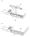
FIG. 3 , the anodeterminal connection part 220 and a cathodeterminal connection part 230 formed at thePCB 200 are welded to theanode terminal 120 and thecathode terminal 110 of thebattery cell 100, respectively, for example, by spot welding. In a case in which thenickel plate 140 is welded to thecathode terminal 110 as shown inFIG. 2 , the cathodeterminal connection part 230 is welded to thenickel plate 140. - Since the anode
terminal connection part 220 and the cathodeterminal connection part 230 each include a part coupled to thePCB 200 and a bendable extension part as described above, the anodeterminal connection part 220 and the cathodeterminal connection part 230 of thePCB 200 may be coupled to theanode terminal 120 and thecathode terminal 110 of thebattery cell 100, respectively, by welding so that thePCB 200 is opposite to one face of thebattery cell 100 at which the sealedsurplus portion 130 is formed, as can be seen fromFIG. 3 . - Referring to
FIG. 4 together withFIG. 1 , after the anodeterminal connection part 220 and the cathodeterminal connection part 230 are bent, anadhesive tape 160, serving as an insulation tape, may be attached to an electrode terminal exposure region of the sealedsurplus portion 130 of the main body of thebattery cell 100. In a case in which the insulation tape is further attached to the electrode terminal exposure region of the sealedsurplus portion 130 as described above, it is possible to more effectively improve insulativity of the electrode terminal exposure region. Also, in a case in which the insulation tape is a double-sided tape, the double-side tape provides coupling force between the PCM case and the sealed surplus portion when the PCM case is mounted to the PCB, thereby further improving structural stability. - In the embodiment of the present invention, the
PCB 200, connected to thebattery cell 100 via the anode terminal connection part and the cathode terminal connection part, may be disposed in the PCM case in a state in which thePCB 200 is parallel to thebattery cell 100, and may be mounted to the sealed surplus portion of thebattery cell 100. Here, the state in which thePCB 200 is parallel to thebattery cell 100 may be, for example, a state in which the anodeterminal connection part 220 and the cathodeterminal connection part 230, connected to the anode terminal and the cathode terminal of the battery cell, are disposed so as to face upward as shown inFIG. 4 . In this case, as shown inFIG. 4 , thePCB 200 may be spaced apart from the end of the battery cell at which the sealed surplus portion is formed by the connection length between the anode terminal and the anode terminal connection part and between the cathode terminal and the cathode terminal connection part in the longitudinal direction so that thePCB 200 is parallel to the sealed surplus portion. - In other words, in a case in which the
PCB 200 is disposed in parallel to the battery cell, as shown inFIG. 4 , the face of thePCB 200 at which the anodeterminal connection part 220 and the cathodeterminal connection part 230 are located, faces upward with the result that two widest ones of the four faces constituting the external appearance of thePCB 200 face upward and downward. Also, since the two widest ones of the four faces constituting the external appearance of thePCB 200 face upward and downward, the two widest faces of thePCB 200 and two widest faces of thebattery cell 100 are disposed so as to face in the same directions. Consequently, that thePCB 200 is disposed in parallel to thebattery cell 100 may be understood as including the above-mentioned positional relationship. - Referring to
FIG. 5 , the board may be disposed in the PCM case in a state in which the board is parallel to the battery cell in an extension direction identical to an extension direction of the sealed surplus portion. As previously described in connection withFIG. 1 , thePCM case 300 is opened at one face thereof so that thePCM case 300 receives thePCB 200 through the open face. Also, in a case in which the external input andoutput terminal 210 is connected to the connection parts of thePCB 200 via the interconnection part as shown inFIG. 1 , an opening, e.g. a slit type opening 310, may be formed at one face of thePCM case 300 corresponding to theinterconnection part 211 of thePCB 200 so that the external input andoutput terminal 210 is exposed outside. Since theinterconnection part 211 of thePCB 200 extends through the slit type opening 310, the external input andoutput terminal 210 connected to theinterconnection part 211 is exposed outside. - The PCM case may be mounted to the battery cell in a state in which the opening faces upward as shown in
FIG. 1 or in an arrow direction as shown inFIG. 5 . Also, the PCM case may be mounted to the battery cell in a state in which the board is perpendicular to the battery cell as well as in a state in which the board is parallel to the battery cell, as previously described. - Referring to
FIG. 6 together withFIGS. 1 and8 , theanode terminal 120 and thecathode terminal 110 are bent toward one face of the battery cell at which the sealedsurplus portion 130 is formed so that thePCM case 300 is mounted to the sealedsurplus portion 130 of thebattery cell 100. - When the
PCB 200 is mounted to the sealedsurplus portion 130 formed at one face of thebattery cell 100 as described above, thePCB 200 is mounted perpendicularly to the sealedsurplus portion 130. In a case in which it is difficult for the sealedsurplus portion 130 to have a sufficient size, therefore, the size of thePCB 200 may be reduced. - Referring to
FIGS. 7 and 8 together withFIG. 10 , thePCM case 300, in which the board is disposed, is opened at one face thereof. As previously described in connection withFIG. 1 , the open face of thePCM case 300 may be closed by theelectrically insulative lid 600. Also, as shown inFIG. 7 , the electricallyinsulative lid 600 is provided with thehooks 610 corresponding to thefastening grooves 320 of thePCM case 300, and thePCM case 300 is provided with thefastening grooves 320 corresponding to thehooks 610 of theelectrically insulative lid 600. Consequently, thePCM case 300 and theelectrically insulative lid 600 may be coupled to each other through an assembly type fastening structure. - Also, the position and shape of the fastening grooves and fastening protrusions (for example, hooks) are not particularly restricted so long as the PCM case and the lid are coupled to each other by the fastening grooves and the fastening protrusions.
-
FIG. 9 is a view showing a state in which alabel 400 covers thePCM case 300 and thebattery cell 100 in a state in which thePCB 200 mounted to sealedsurplus portion 130 of thebattery cell 100 is disposed in thePCM case 300. Thelabel 400 according to the present invention may be configured to cover the outer faces of thePCM case 300 and the sealed outer circumferences of the battery cell 100 (see arrow directions inFIG. 9 ) so that the external input and output terminal can be exposed outside. For example, as shown inFIG. 9 , thelabel 500 may be attached to cover the outer faces of thePCM 500 and the sealed outer circumferences of thebattery cell 100 excluding the external input andoutput terminal 210 exposed outside. - In a case in which the
label 400 is attached to the battery cell, it is possible to stably fix the sealed outer circumferences of the battery cell to the main body of the battery cell while maintaining the overall insulation state, thereby more stably securing the electrical connection state between the electrode terminals of the battery cell and the PCB. -
FIG. 11 is a perspective view of a secondary battery pack according to another embodiment of the present invention configured so that an external input and output terminal is mounted to a PCB. Referring toFIG. 11 , as previously described, asecondary battery pack 800 is configured to have a structure in which an external input andoutput terminal 430 is formed at one face of the PCB (not shown) so that the external input andoutput terminal 430 is exposed outside through aPCM case 420. - As is apparent from the above description, the secondary battery pack according to the present invention is configured so that the
PCM 500, in which the protection circuit board electrically connected to the cathode terminal and the anode terminal of the battery cell is disposed in the case, is mounted to the sealed surplus portion formed at one face of the battery cell. Consequently, it is possible to effectively protect the PCM and to greatly reduce the number of parts constituting the secondary battery pack, thereby greatly improving manufacturing efficiency, as compared with the conventional secondary battery pack. - Also, the secondary battery pack according to the present invention is configured so that the protection circuit board is disposed in the electrically insulative case. Consequently, it is possible to protect and insulate the PCM including the protection circuit board. Also, it is possible to easily prevent the electrode terminals from being exposed outside without insulation of the electrode terminals through the use of additional members.
- Furthermore, the secondary battery pack according to the present invention is configured so that the protection circuit board is mounted in the case. Consequently, it is possible to easily manufacture the secondary battery pack, to relatively reduce a defect rate, and to configure the secondary battery pack so that the secondary battery pack has no wrinkles formed at the outer face thereof, i.e. a neat and clean external appearance, as compared with the conventional secondary battery pack in which the PCM is insulated using a tape.
- In addition, the secondary battery pack according to the present invention is configured so that the protection circuit board is mounted to the sealed surplus portion formed at one face of the battery cell. Consequently, it is possible to reduce the length of the sealed surplus portion and to increase the capacity of the battery pack per unit volume, as compared with the conventional secondary battery pack.
- Meanwhile, in a general process of assembling the secondary battery pack, the connection members and the PCM are coupled, and an insulative tape is attached at each step, to the PCM assembly is mounted to the battery cell, as previously described. That is, the PCM assembly is mounted to the battery cell using a plurality of parts with the result that a plurality of processes is required, and structural stability as well as mechanical strength is low.
- On the other hand, the protection circuit module according to the present invention is configured to have a structure in which the protection circuit board is mounted in the case, and therefore, it is possible to improve structural stability of the battery pack, to greatly simplify the process of manufacturing the battery pack, to secure excellent insulativity, and to maximize the capacity of the battery cell in the battery pack having the same standard as the conventional battery pack.
- Also, in the manufacturing method according to the present invention, it is possible to protect and insulate the PCM using the case without an additional member, such as a label or an insulative tape. Also, the protection circuit board is electrically connected to the electrode terminals, the electrode terminals are bent, and then the protection circuit board is mounted in the case with the result that no exposed region is formed during the bending process, and therefore, an additional insulative member is not required.
- Although the exemplary embodiments of the present invention have been disclosed for illustrative purposes, those skilled in the art will appreciate that vario us modifications, additions and substitutions are possible, without departing from the scope and spirit of the invention as disclosed in the accompanying claims.
Claims (27)
- A secondary battery pack comprising:a battery cell having an anode terminal and a cathode terminal formed at one face having a sealed surplus portion; anda protection circuit module (PCM) electrically connected to the battery cell via the anode terminal and the cathode terminal, whereinthe PCM comprises:a board having a protection circuit formed thereon, the board being provided with an anode terminal connection part and a cathode terminal connection part connected to the anode terminal and the cathode terminal, respectively; anda PCM case configured to receive the board through an open face thereof so that the PCM case surrounds the board,the board is coupled to the anode terminal and the cathode terminal of the battery cell via the anode terminal connection part and the cathode terminal connection part, the board is disposed in the PCM case in a state in which the board is parallel to the battery cell, and the PCM case, in which the board is disposed, is mounted to the sealed surplus portion of the battery cell, andthe PCM further comprises an electrically insulative lid to close the open face of the PCM case.
- The secondary battery pack according to claim 1, wherein the PCM case and the lid are coupled to each other through an assembly type fastening structure.
- The secondary battery pack according to claim 2, wherein the PCM case is provided with at least one fastening groove for coupling with the lid, and the lid is provided with at least one fastening protrusion corresponding to the at least one fastening groove of the PCM case.
- The secondary battery pack according to claim 1, wherein the battery cell is a plate-shaped battery cell, and the anode terminal and the cathode terminal are plate-shaped conductive members.
- The secondary battery pack according to claim 1, wherein the board further comprises an external input and output terminal.
- The secondary battery pack according to claim 5, wherein the external input and output terminal is formed at the board at which the anode terminal connection part and the cathode terminal connection part are formed via an interconnection part.
- The secondary battery pack according to claim 5, wherein the external input and output terminal is formed on the board at which the anode terminal connection part and the cathode terminal connection part are formed.
- The secondary battery pack according to claim 5, wherein the external input and output terminal is formed at the other face of the board at which the anode terminal connection part and the cathode terminal connection part are formed.
- The secondary battery pack according to claim 6, wherein the PCM case further comprises an opening, through which the external input and output terminal is drawn, formed at a face adjacent to the open face thereof.
- The secondary battery pack according to claim 9, wherein the opening is a slit type opening.
- The secondary battery pack according to claim 1, further comprising an insulative tape additionally attached to an electrode terminal exposure region of the sealed surplus portion.
- The secondary battery pack according to claim 11, wherein the insulative tape is a double-sided tape.
- The secondary battery pack according to claim 1, further comprising an insulative tape additionally attached to at least one of outer faces of the PCM case.
- The secondary battery pack according to claim 1, wherein the battery cell is configured to have a structure in which an electrode assembly, comprising cathodes, anodes, and separators respectively disposed between the cathodes and the anodes, is disposed in a battery case made of a laminate sheet comprising a metal layer and a resin layer in a sealed state.
- The secondary battery pack according to claim 1, wherein the board is disposed in the PCM case in a state in which the board is parallel to the battery cell in an extension direction identical to an extension direction of the sealed surplus portion.
- The secondary battery pack according to claim 1, further comprising a nickel plate additionally mounted to one face of the cathode terminal, to which the cathode terminal connection part of the board is coupled, by ultrasonic welding.
- The secondary battery pack according to claim 1, further comprising a label to cover the battery cell.
- The secondary battery pack according to claim 17, wherein the label is configured to have a structure to cover sealed outer circumferences of the battery cell.
- A protection circuit module comprising:a protection circuit board having an anode terminal connection part and a cathode terminal connection part connected to an anode terminal and a cathode terminal of a battery cell, respectively; anda PCM case configured to receive the protection circuit board through an open face thereof, whereinthe protection circuit board is coupled to the anode terminal and the cathode terminal of the battery cell via the anode terminal connection part and the cathode terminal connection part, the board is disposed in the PCM case in a state in which the board is parallel to the battery cell, and the PCM case, in which the board is disposed, is mounted to the sealed surplus portion of the battery cell, andan electrically insulative lid is mounted to the PCM case to close the open face of the PCM case.
- The protection circuit module according to claim 19, wherein the PCM case and the lid are coupled to each other through an assembly type fastening structure.
- The protection circuit module according to claim 19, wherein the PCM case is provided with at least one fastening groove for coupling with the lid, and the lid is provided with at least one fastening protrusion corresponding to the at least one fastening groove of the PCM case.
- The protection circuit module according to claim 19, wherein the PCM case is configured to have a hollow box structure opened at one face thereof
- The protection circuit module according to claim 19, wherein the protection circuit board further comprises an external input and output terminal coupled to the board at which the anode terminal connection part and the cathode terminal connection part are formed via an interconnection part.
- The protection circuit module according to claim 23, wherein the PCM case further comprises an opening, through which the interconnection part extends, formed at a face adjacent to the open face thereof.
- The protection circuit module according to claim 24, wherein the PCM case comprises a slit type opening.
- A method of manufacturing a secondary battery pack comprising:a step of forming a battery cell configured to have a structure in which an electrode assembly, comprising cathodes, anodes, and separators respectively disposed between the cathodes and the anodes, is disposed in a battery case in a sealed state, one of sealed outer circumferences of the battery cell having a surplus portion;a step of receiving a board into a PCM case opened at one face thereof in an extension direction identical to an extension direction of the sealed surplus portion in a state in which the board is parallel to the battery cell;a step of mounting the PCM case to the sealed surplus portion of the battery cell; anda step of mounting an electrically insulative lid to the PCM case to close the open face of the PCM case.
- A secondary battery pack comprising:a battery cell having an anode terminal and a cathode terminal formed at one face having a sealed surplus portion; anda protection circuit module (PCM) electrically connected to the battery cell via the anode terminal and the cathode terminal, whereinthe PCM comprises:a board having a protection circuit formed thereon, the board being provided with an anode terminal connection part and a cathode terminal connection part connected to the anode terminal and the cathode terminal, respectively; anda PCM case configured to receive the board through an open face thereof so that the PCM case surrounds the board,the board is coupled to the anode terminal and the cathode terminal of the battery cell via the anode terminal connection part and the cathode terminal connection part, the board is disposed in the PCM case in a state in which the board is perpendicular to the battery cell, and the PCM case, in which the board is disposed, is mounted to the sealed surplus portion of the battery cell, andthe PCM further comprises an electrically insulative lid to close the open face of the PCM case.
Applications Claiming Priority (3)
| Application Number | Priority Date | Filing Date | Title |
|---|---|---|---|
| KR20110078989 | 2011-08-09 | ||
| KR1020120014792A KR20130018477A (en) | 2011-08-09 | 2012-02-14 | Secondary battery pack of novel structure |
| PCT/KR2012/006128 WO2013022211A2 (en) | 2011-08-09 | 2012-08-01 | Secondary battery pack |
Publications (3)
| Publication Number | Publication Date |
|---|---|
| EP2744017A2 true EP2744017A2 (en) | 2014-06-18 |
| EP2744017A4 EP2744017A4 (en) | 2015-03-18 |
| EP2744017B1 EP2744017B1 (en) | 2017-06-21 |
Family
ID=47897234
Family Applications (1)
| Application Number | Title | Priority Date | Filing Date |
|---|---|---|---|
| EP12821536.5A Active EP2744017B1 (en) | 2011-08-09 | 2012-08-01 | Secondary battery pack |
Country Status (8)
| Country | Link |
|---|---|
| US (1) | US9793704B2 (en) |
| EP (1) | EP2744017B1 (en) |
| JP (1) | JP5947381B2 (en) |
| KR (3) | KR20130018477A (en) |
| CN (2) | CN103718342B (en) |
| BR (1) | BR112014003053B8 (en) |
| TW (1) | TWI482328B (en) |
| WO (1) | WO2013022211A2 (en) |
Cited By (5)
| Publication number | Priority date | Publication date | Assignee | Title |
|---|---|---|---|---|
| EP2731174A4 (en) * | 2011-08-12 | 2015-01-21 | Lg Chemical Ltd | SECONDARY BATTERY PACK |
| EP3035415A4 (en) * | 2013-09-27 | 2016-06-22 | Lg Chemical Ltd | RECHARGEABLE BATTERY COMPRISING A PROTECTION CIRCUIT MODULE |
| EP3038191A4 (en) * | 2013-09-30 | 2016-08-31 | Lg Chemical Ltd | BATTERY PACK COMPRISING A PROTECTIVE CIRCUIT MODULE HOUSING |
| EP3113251A4 (en) * | 2014-04-29 | 2017-02-08 | LG Chem, Ltd. | Battery pack including protection circuit module fixing part |
| EP3618143A4 (en) * | 2018-01-09 | 2020-07-29 | Lg Chem, Ltd. | BATTERY PACK WITH DETACHABLE PAPER COVER |
Families Citing this family (18)
| Publication number | Priority date | Publication date | Assignee | Title |
|---|---|---|---|---|
| KR20130018478A (en) | 2011-08-09 | 2013-02-25 | 주식회사 엘지화학 | Secondary battery pack of novel structure |
| KR101619925B1 (en) * | 2013-09-27 | 2016-05-12 | 주식회사 엘지화학 | Battery Pack Having PCM Fixing Tape |
| KR101619926B1 (en) * | 2013-09-27 | 2016-05-12 | 주식회사 엘지화학 | Battery Pack Having PCM Case |
| KR101699855B1 (en) * | 2013-09-30 | 2017-01-25 | 주식회사 엘지화학 | Battery Pack Having Electric Insulating Member |
| KR101684358B1 (en) | 2013-09-30 | 2016-12-20 | 주식회사 엘지화학 | Battery Pack Having Electric Insulating Pack Case |
| KR20150037040A (en) * | 2013-09-30 | 2015-04-08 | 주식회사 엘지화학 | Secondary Battery Pack Having Battery Cells Mounted in Cartridge Frame |
| KR102152364B1 (en) * | 2013-12-05 | 2020-09-04 | 삼성에스디아이 주식회사 | Battery pack |
| KR102222111B1 (en) * | 2014-08-01 | 2021-03-03 | 삼성에스디아이 주식회사 | Secondary battery |
| KR101678528B1 (en) * | 2014-08-07 | 2016-11-22 | 삼성에스디아이 주식회사 | Battery pack |
| KR20160020284A (en) * | 2014-08-13 | 2016-02-23 | 삼성에스디아이 주식회사 | Battery pack |
| KR102324344B1 (en) * | 2015-01-27 | 2021-11-10 | 삼성에스디아이 주식회사 | Battery Pack |
| KR102168675B1 (en) * | 2017-09-28 | 2020-10-21 | 주식회사 엘지화학 | Pouch Type Secondary Battery Pack Having Protection Circuit Module |
| CN115133238A (en) * | 2018-01-23 | 2022-09-30 | 东莞新能德科技有限公司 | Battery and preparation method thereof |
| CN208142237U (en) | 2018-01-25 | 2018-11-23 | 宁德新能源科技有限公司 | A kind of battery |
| JP7145624B2 (en) * | 2018-03-07 | 2022-10-03 | マクセル株式会社 | laminated battery |
| KR102519555B1 (en) * | 2018-06-12 | 2023-04-07 | 삼성에스디아이 주식회사 | Battery Pack |
| CN111403803B (en) * | 2020-04-30 | 2022-06-03 | 东莞新能德科技有限公司 | Battery and electronic device with same |
| CN114976507B (en) * | 2022-06-30 | 2024-12-31 | 东莞新能安科技有限公司 | Battery packs and electrical equipment |
Family Cites Families (28)
| Publication number | Priority date | Publication date | Assignee | Title |
|---|---|---|---|---|
| KR100890715B1 (en) * | 2000-11-01 | 2009-03-27 | 소니 가부시끼 가이샤 | Battery, Method for Manufacturing Battery, Method for Manufacturing Weld and Pedestal |
| JP2003019569A (en) * | 2001-07-04 | 2003-01-21 | At Battery:Kk | Resistance welding method, battery pack manufactured using the same |
| JP3762737B2 (en) | 2002-10-30 | 2006-04-05 | 三洋電機株式会社 | Battery pack |
| JP3922281B2 (en) * | 2003-11-14 | 2007-05-30 | ソニー株式会社 | Battery pack and battery pack manufacturing method |
| KR100682731B1 (en) | 2004-02-13 | 2007-02-15 | 주식회사 엘지화학 | Improved battery pack |
| KR100601519B1 (en) * | 2004-06-22 | 2006-07-19 | 삼성에스디아이 주식회사 | Pouch-type Lithium Polymer Battery and Manufacturing Method Thereof |
| JP2006066090A (en) * | 2004-08-24 | 2006-03-09 | Sony Corp | Battery pack and manufacturing method thereof |
| JP5044934B2 (en) * | 2005-01-21 | 2012-10-10 | ソニー株式会社 | Battery pack |
| JP5011678B2 (en) * | 2005-08-12 | 2012-08-29 | ソニー株式会社 | Secondary battery |
| KR100932224B1 (en) * | 2005-09-02 | 2009-12-16 | 주식회사 엘지화학 | Secondary battery with no welding connection |
| JP2008041621A (en) * | 2006-08-10 | 2008-02-21 | Nec Tokin Corp | Method for manufacturing battery pack |
| JP2008159555A (en) * | 2006-12-20 | 2008-07-10 | Alfact Co Ltd | Connection tab for battery |
| JP5254332B2 (en) * | 2007-07-19 | 2013-08-07 | エルジー・ケム・リミテッド | Large capacity battery pack |
| KR101011802B1 (en) * | 2007-12-14 | 2011-02-07 | 주식회사 엘지화학 | Secondary Battery Packs and PCCs with Excellent Manufacturing Process |
| KR101012728B1 (en) | 2007-12-14 | 2011-02-09 | 주식회사 엘지화학 | Secondary battery pack including new structured PCM assembly and insulating mounting member |
| JP4980286B2 (en) * | 2008-04-01 | 2012-07-18 | ソニー株式会社 | Battery pack and battery case |
| KR101134393B1 (en) * | 2009-01-09 | 2012-04-12 | 주식회사 엘지화학 | Battery Pack of Novel Structure |
| JP2011070906A (en) * | 2009-09-25 | 2011-04-07 | Sony Corp | Battery pack and holder |
| KR101075278B1 (en) * | 2009-10-09 | 2011-10-19 | 삼성에스디아이 주식회사 | Secondary battery |
| KR101182135B1 (en) * | 2009-12-11 | 2012-09-12 | 주식회사 엘지화학 | Secondary Battery Pack of Embedded Type with Structure of Excellent Stability |
| US20140336355A1 (en) * | 2011-07-13 | 2014-11-13 | Instraction Gmbh | Ion-exchanger material with high salt-tolerance |
| KR20130016034A (en) * | 2011-08-04 | 2013-02-14 | 주식회사 엘지화학 | Secondary battery pack with improved safety |
| KR20130016035A (en) * | 2011-08-04 | 2013-02-14 | 주식회사 엘지화학 | Secondary battery pack of novel structure |
| KR20130018478A (en) | 2011-08-09 | 2013-02-25 | 주식회사 엘지화학 | Secondary battery pack of novel structure |
| KR20130018098A (en) * | 2011-08-12 | 2013-02-20 | 주식회사 엘지화학 | Secondary battery pack of novel structure |
| KR20130018097A (en) * | 2011-08-12 | 2013-02-20 | 주식회사 엘지화학 | Secondary battery pack of novel structure |
| KR20130065291A (en) * | 2011-12-09 | 2013-06-19 | 삼성에스디아이 주식회사 | Battery pack |
| US9385402B2 (en) * | 2012-02-22 | 2016-07-05 | Lg Chem, Ltd. | Secondary battery pack of embedded type with novel structure |
-
2012
- 2012-02-14 KR KR1020120014792A patent/KR20130018477A/en active Pending
- 2012-08-01 JP JP2014524918A patent/JP5947381B2/en active Active
- 2012-08-01 BR BR112014003053A patent/BR112014003053B8/en active IP Right Grant
- 2012-08-01 EP EP12821536.5A patent/EP2744017B1/en active Active
- 2012-08-01 CN CN201280038444.3A patent/CN103718342B/en active Active
- 2012-08-01 KR KR1020120084338A patent/KR101259944B1/en active Active
- 2012-08-01 WO PCT/KR2012/006128 patent/WO2013022211A2/en not_active Ceased
- 2012-08-07 TW TW101128455A patent/TWI482328B/en active
- 2012-08-09 CN CN2012203935290U patent/CN203218397U/en not_active Expired - Lifetime
-
2013
- 2013-02-18 KR KR1020130016679A patent/KR101293591B1/en active Active
-
2014
- 2014-01-29 US US14/167,576 patent/US9793704B2/en active Active
Cited By (9)
| Publication number | Priority date | Publication date | Assignee | Title |
|---|---|---|---|---|
| EP2731174A4 (en) * | 2011-08-12 | 2015-01-21 | Lg Chemical Ltd | SECONDARY BATTERY PACK |
| US9083028B2 (en) | 2011-08-12 | 2015-07-14 | Lg Chem, Ltd. | Secondary battery pack of novel structure |
| EP3035415A4 (en) * | 2013-09-27 | 2016-06-22 | Lg Chemical Ltd | RECHARGEABLE BATTERY COMPRISING A PROTECTION CIRCUIT MODULE |
| US10388938B2 (en) | 2013-09-27 | 2019-08-20 | Lg Chem, Ltd. | Secondary battery pack having PCM |
| EP3038191A4 (en) * | 2013-09-30 | 2016-08-31 | Lg Chemical Ltd | BATTERY PACK COMPRISING A PROTECTIVE CIRCUIT MODULE HOUSING |
| US9929442B2 (en) | 2013-09-30 | 2018-03-27 | Lg Chem, Ltd. | Battery pack having PCM case |
| EP3113251A4 (en) * | 2014-04-29 | 2017-02-08 | LG Chem, Ltd. | Battery pack including protection circuit module fixing part |
| EP3618143A4 (en) * | 2018-01-09 | 2020-07-29 | Lg Chem, Ltd. | BATTERY PACK WITH DETACHABLE PAPER COVER |
| US11024929B2 (en) | 2018-01-09 | 2021-06-01 | Lg Chem, Ltd. | Battery pack including release cover |
Also Published As
| Publication number | Publication date |
|---|---|
| TWI482328B (en) | 2015-04-21 |
| WO2013022211A2 (en) | 2013-02-14 |
| KR20130030285A (en) | 2013-03-26 |
| KR20130018576A (en) | 2013-02-25 |
| EP2744017A4 (en) | 2015-03-18 |
| KR101293591B1 (en) | 2013-08-13 |
| CN103718342B (en) | 2016-11-23 |
| US9793704B2 (en) | 2017-10-17 |
| US20140147707A1 (en) | 2014-05-29 |
| CN103718342A (en) | 2014-04-09 |
| TW201336142A (en) | 2013-09-01 |
| JP5947381B2 (en) | 2016-07-06 |
| BR112014003053A2 (en) | 2017-02-21 |
| JP2014522089A (en) | 2014-08-28 |
| KR20130018477A (en) | 2013-02-25 |
| KR101259944B1 (en) | 2013-05-02 |
| BR112014003053B8 (en) | 2023-01-17 |
| WO2013022211A3 (en) | 2013-04-04 |
| EP2744017B1 (en) | 2017-06-21 |
| CN203218397U (en) | 2013-09-25 |
| BR112014003053B1 (en) | 2021-06-08 |
Similar Documents
| Publication | Publication Date | Title |
|---|---|---|
| EP2744017B1 (en) | Secondary battery pack | |
| EP2725639B1 (en) | Secondary battery pack | |
| EP2731174B1 (en) | Secondary battery pack | |
| EP2731175B1 (en) | Secondary battery pack | |
| EP2731172B1 (en) | Secondary battery pack | |
| EP2733775B1 (en) | Secondary battery pack | |
| EP2728649B1 (en) | Secondary battery pack |
Legal Events
| Date | Code | Title | Description |
|---|---|---|---|
| PUAI | Public reference made under article 153(3) epc to a published international application that has entered the european phase |
Free format text: ORIGINAL CODE: 0009012 |
|
| 17P | Request for examination filed |
Effective date: 20140131 |
|
| AK | Designated contracting states |
Kind code of ref document: A2 Designated state(s): AL AT BE BG CH CY CZ DE DK EE ES FI FR GB GR HR HU IE IS IT LI LT LU LV MC MK MT NL NO PL PT RO RS SE SI SK SM TR |
|
| DAX | Request for extension of the european patent (deleted) | ||
| A4 | Supplementary search report drawn up and despatched |
Effective date: 20150218 |
|
| RIC1 | Information provided on ipc code assigned before grant |
Ipc: H01M 2/34 20060101AFI20150212BHEP Ipc: H01M 2/30 20060101ALI20150212BHEP Ipc: H01M 2/26 20060101ALI20150212BHEP |
|
| REG | Reference to a national code |
Ref country code: DE Ref legal event code: R079 Ref document number: 602012033789 Country of ref document: DE Free format text: PREVIOUS MAIN CLASS: H01M0002340000 Ipc: H01M0002020000 |
|
| GRAP | Despatch of communication of intention to grant a patent |
Free format text: ORIGINAL CODE: EPIDOSNIGR1 |
|
| STAA | Information on the status of an ep patent application or granted ep patent |
Free format text: STATUS: GRANT OF PATENT IS INTENDED |
|
| RIC1 | Information provided on ipc code assigned before grant |
Ipc: H01M 2/20 20060101ALN20170116BHEP Ipc: H01M 2/02 20060101AFI20170116BHEP Ipc: H01M 2/10 20060101ALN20170116BHEP Ipc: H01M 10/04 20060101ALN20170116BHEP Ipc: H01M 2/22 20060101ALN20170116BHEP Ipc: H01M 10/42 20060101ALI20170116BHEP Ipc: H01M 2/04 20060101ALN20170116BHEP Ipc: H01M 2/08 20060101ALN20170116BHEP |
|
| INTG | Intention to grant announced |
Effective date: 20170221 |
|
| GRAS | Grant fee paid |
Free format text: ORIGINAL CODE: EPIDOSNIGR3 |
|
| GRAA | (expected) grant |
Free format text: ORIGINAL CODE: 0009210 |
|
| STAA | Information on the status of an ep patent application or granted ep patent |
Free format text: STATUS: THE PATENT HAS BEEN GRANTED |
|
| AK | Designated contracting states |
Kind code of ref document: B1 Designated state(s): AL AT BE BG CH CY CZ DE DK EE ES FI FR GB GR HR HU IE IS IT LI LT LU LV MC MK MT NL NO PL PT RO RS SE SI SK SM TR |
|
| REG | Reference to a national code |
Ref country code: GB Ref legal event code: FG4D |
|
| REG | Reference to a national code |
Ref country code: CH Ref legal event code: EP |
|
| REG | Reference to a national code |
Ref country code: IE Ref legal event code: FG4D |
|
| REG | Reference to a national code |
Ref country code: AT Ref legal event code: REF Ref document number: 903658 Country of ref document: AT Kind code of ref document: T Effective date: 20170715 |
|
| REG | Reference to a national code |
Ref country code: DE Ref legal event code: R096 Ref document number: 602012033789 Country of ref document: DE |
|
| REG | Reference to a national code |
Ref country code: FR Ref legal event code: PLFP Year of fee payment: 6 |
|
| REG | Reference to a national code |
Ref country code: NL Ref legal event code: MP Effective date: 20170621 |
|
| PG25 | Lapsed in a contracting state [announced via postgrant information from national office to epo] |
Ref country code: GR Free format text: LAPSE BECAUSE OF FAILURE TO SUBMIT A TRANSLATION OF THE DESCRIPTION OR TO PAY THE FEE WITHIN THE PRESCRIBED TIME-LIMIT Effective date: 20170922 Ref country code: HR Free format text: LAPSE BECAUSE OF FAILURE TO SUBMIT A TRANSLATION OF THE DESCRIPTION OR TO PAY THE FEE WITHIN THE PRESCRIBED TIME-LIMIT Effective date: 20170621 Ref country code: LT Free format text: LAPSE BECAUSE OF FAILURE TO SUBMIT A TRANSLATION OF THE DESCRIPTION OR TO PAY THE FEE WITHIN THE PRESCRIBED TIME-LIMIT Effective date: 20170621 Ref country code: FI Free format text: LAPSE BECAUSE OF FAILURE TO SUBMIT A TRANSLATION OF THE DESCRIPTION OR TO PAY THE FEE WITHIN THE PRESCRIBED TIME-LIMIT Effective date: 20170621 Ref country code: NO Free format text: LAPSE BECAUSE OF FAILURE TO SUBMIT A TRANSLATION OF THE DESCRIPTION OR TO PAY THE FEE WITHIN THE PRESCRIBED TIME-LIMIT Effective date: 20170921 |
|
| REG | Reference to a national code |
Ref country code: LT Ref legal event code: MG4D |
|
| REG | Reference to a national code |
Ref country code: AT Ref legal event code: MK05 Ref document number: 903658 Country of ref document: AT Kind code of ref document: T Effective date: 20170621 |
|
| PG25 | Lapsed in a contracting state [announced via postgrant information from national office to epo] |
Ref country code: NL Free format text: LAPSE BECAUSE OF FAILURE TO SUBMIT A TRANSLATION OF THE DESCRIPTION OR TO PAY THE FEE WITHIN THE PRESCRIBED TIME-LIMIT Effective date: 20170621 Ref country code: LV Free format text: LAPSE BECAUSE OF FAILURE TO SUBMIT A TRANSLATION OF THE DESCRIPTION OR TO PAY THE FEE WITHIN THE PRESCRIBED TIME-LIMIT Effective date: 20170621 Ref country code: SE Free format text: LAPSE BECAUSE OF FAILURE TO SUBMIT A TRANSLATION OF THE DESCRIPTION OR TO PAY THE FEE WITHIN THE PRESCRIBED TIME-LIMIT Effective date: 20170621 Ref country code: RS Free format text: LAPSE BECAUSE OF FAILURE TO SUBMIT A TRANSLATION OF THE DESCRIPTION OR TO PAY THE FEE WITHIN THE PRESCRIBED TIME-LIMIT Effective date: 20170621 Ref country code: BG Free format text: LAPSE BECAUSE OF FAILURE TO SUBMIT A TRANSLATION OF THE DESCRIPTION OR TO PAY THE FEE WITHIN THE PRESCRIBED TIME-LIMIT Effective date: 20170921 |
|
| PG25 | Lapsed in a contracting state [announced via postgrant information from national office to epo] |
Ref country code: SK Free format text: LAPSE BECAUSE OF FAILURE TO SUBMIT A TRANSLATION OF THE DESCRIPTION OR TO PAY THE FEE WITHIN THE PRESCRIBED TIME-LIMIT Effective date: 20170621 Ref country code: AT Free format text: LAPSE BECAUSE OF FAILURE TO SUBMIT A TRANSLATION OF THE DESCRIPTION OR TO PAY THE FEE WITHIN THE PRESCRIBED TIME-LIMIT Effective date: 20170621 Ref country code: CZ Free format text: LAPSE BECAUSE OF FAILURE TO SUBMIT A TRANSLATION OF THE DESCRIPTION OR TO PAY THE FEE WITHIN THE PRESCRIBED TIME-LIMIT Effective date: 20170621 Ref country code: EE Free format text: LAPSE BECAUSE OF FAILURE TO SUBMIT A TRANSLATION OF THE DESCRIPTION OR TO PAY THE FEE WITHIN THE PRESCRIBED TIME-LIMIT Effective date: 20170621 Ref country code: RO Free format text: LAPSE BECAUSE OF FAILURE TO SUBMIT A TRANSLATION OF THE DESCRIPTION OR TO PAY THE FEE WITHIN THE PRESCRIBED TIME-LIMIT Effective date: 20170621 |
|
| PG25 | Lapsed in a contracting state [announced via postgrant information from national office to epo] |
Ref country code: ES Free format text: LAPSE BECAUSE OF FAILURE TO SUBMIT A TRANSLATION OF THE DESCRIPTION OR TO PAY THE FEE WITHIN THE PRESCRIBED TIME-LIMIT Effective date: 20170621 Ref country code: PL Free format text: LAPSE BECAUSE OF FAILURE TO SUBMIT A TRANSLATION OF THE DESCRIPTION OR TO PAY THE FEE WITHIN THE PRESCRIBED TIME-LIMIT Effective date: 20170621 Ref country code: SM Free format text: LAPSE BECAUSE OF FAILURE TO SUBMIT A TRANSLATION OF THE DESCRIPTION OR TO PAY THE FEE WITHIN THE PRESCRIBED TIME-LIMIT Effective date: 20170621 Ref country code: IT Free format text: LAPSE BECAUSE OF FAILURE TO SUBMIT A TRANSLATION OF THE DESCRIPTION OR TO PAY THE FEE WITHIN THE PRESCRIBED TIME-LIMIT Effective date: 20170621 Ref country code: IS Free format text: LAPSE BECAUSE OF FAILURE TO SUBMIT A TRANSLATION OF THE DESCRIPTION OR TO PAY THE FEE WITHIN THE PRESCRIBED TIME-LIMIT Effective date: 20171021 |
|
| REG | Reference to a national code |
Ref country code: DE Ref legal event code: R097 Ref document number: 602012033789 Country of ref document: DE |
|
| REG | Reference to a national code |
Ref country code: CH Ref legal event code: PL |
|
| PG25 | Lapsed in a contracting state [announced via postgrant information from national office to epo] |
Ref country code: MC Free format text: LAPSE BECAUSE OF FAILURE TO SUBMIT A TRANSLATION OF THE DESCRIPTION OR TO PAY THE FEE WITHIN THE PRESCRIBED TIME-LIMIT Effective date: 20170621 |
|
| PLBE | No opposition filed within time limit |
Free format text: ORIGINAL CODE: 0009261 |
|
| STAA | Information on the status of an ep patent application or granted ep patent |
Free format text: STATUS: NO OPPOSITION FILED WITHIN TIME LIMIT |
|
| PG25 | Lapsed in a contracting state [announced via postgrant information from national office to epo] |
Ref country code: DK Free format text: LAPSE BECAUSE OF FAILURE TO SUBMIT A TRANSLATION OF THE DESCRIPTION OR TO PAY THE FEE WITHIN THE PRESCRIBED TIME-LIMIT Effective date: 20170621 Ref country code: CH Free format text: LAPSE BECAUSE OF NON-PAYMENT OF DUE FEES Effective date: 20170831 Ref country code: LI Free format text: LAPSE BECAUSE OF NON-PAYMENT OF DUE FEES Effective date: 20170831 |
|
| 26N | No opposition filed |
Effective date: 20180322 |
|
| REG | Reference to a national code |
Ref country code: IE Ref legal event code: MM4A |
|
| REG | Reference to a national code |
Ref country code: BE Ref legal event code: MM Effective date: 20170831 |
|
| PG25 | Lapsed in a contracting state [announced via postgrant information from national office to epo] |
Ref country code: LU Free format text: LAPSE BECAUSE OF NON-PAYMENT OF DUE FEES Effective date: 20170801 |
|
| REG | Reference to a national code |
Ref country code: FR Ref legal event code: PLFP Year of fee payment: 7 |
|
| PG25 | Lapsed in a contracting state [announced via postgrant information from national office to epo] |
Ref country code: IE Free format text: LAPSE BECAUSE OF NON-PAYMENT OF DUE FEES Effective date: 20170801 |
|
| PG25 | Lapsed in a contracting state [announced via postgrant information from national office to epo] |
Ref country code: SI Free format text: LAPSE BECAUSE OF FAILURE TO SUBMIT A TRANSLATION OF THE DESCRIPTION OR TO PAY THE FEE WITHIN THE PRESCRIBED TIME-LIMIT Effective date: 20170621 Ref country code: BE Free format text: LAPSE BECAUSE OF NON-PAYMENT OF DUE FEES Effective date: 20170831 |
|
| PG25 | Lapsed in a contracting state [announced via postgrant information from national office to epo] |
Ref country code: MT Free format text: LAPSE BECAUSE OF NON-PAYMENT OF DUE FEES Effective date: 20170801 |
|
| PG25 | Lapsed in a contracting state [announced via postgrant information from national office to epo] |
Ref country code: HU Free format text: LAPSE BECAUSE OF FAILURE TO SUBMIT A TRANSLATION OF THE DESCRIPTION OR TO PAY THE FEE WITHIN THE PRESCRIBED TIME-LIMIT; INVALID AB INITIO Effective date: 20120801 |
|
| PG25 | Lapsed in a contracting state [announced via postgrant information from national office to epo] |
Ref country code: CY Free format text: LAPSE BECAUSE OF NON-PAYMENT OF DUE FEES Effective date: 20170621 |
|
| PG25 | Lapsed in a contracting state [announced via postgrant information from national office to epo] |
Ref country code: MK Free format text: LAPSE BECAUSE OF FAILURE TO SUBMIT A TRANSLATION OF THE DESCRIPTION OR TO PAY THE FEE WITHIN THE PRESCRIBED TIME-LIMIT Effective date: 20170621 |
|
| PG25 | Lapsed in a contracting state [announced via postgrant information from national office to epo] |
Ref country code: TR Free format text: LAPSE BECAUSE OF FAILURE TO SUBMIT A TRANSLATION OF THE DESCRIPTION OR TO PAY THE FEE WITHIN THE PRESCRIBED TIME-LIMIT Effective date: 20170621 |
|
| PG25 | Lapsed in a contracting state [announced via postgrant information from national office to epo] |
Ref country code: PT Free format text: LAPSE BECAUSE OF FAILURE TO SUBMIT A TRANSLATION OF THE DESCRIPTION OR TO PAY THE FEE WITHIN THE PRESCRIBED TIME-LIMIT Effective date: 20170621 |
|
| PG25 | Lapsed in a contracting state [announced via postgrant information from national office to epo] |
Ref country code: AL Free format text: LAPSE BECAUSE OF FAILURE TO SUBMIT A TRANSLATION OF THE DESCRIPTION OR TO PAY THE FEE WITHIN THE PRESCRIBED TIME-LIMIT Effective date: 20170621 |
|
| REG | Reference to a national code |
Ref country code: DE Ref legal event code: R079 Ref document number: 602012033789 Country of ref document: DE Free format text: PREVIOUS MAIN CLASS: H01M0002020000 Ipc: H01M0050100000 |
|
| REG | Reference to a national code |
Ref country code: DE Ref legal event code: R081 Ref document number: 602012033789 Country of ref document: DE Owner name: LG ENERGY SOLUTION LTD., KR Free format text: FORMER OWNER: LG CHEM, LTD., SEOUL, KR Ref country code: DE Ref legal event code: R081 Ref document number: 602012033789 Country of ref document: DE Owner name: LG ENERGY SOLUTION, LTD., KR Free format text: FORMER OWNER: LG CHEM, LTD., SEOUL, KR |
|
| P01 | Opt-out of the competence of the unified patent court (upc) registered |
Effective date: 20230512 |
|
| REG | Reference to a national code |
Ref country code: GB Ref legal event code: 732E Free format text: REGISTERED BETWEEN 20230824 AND 20230831 |
|
| REG | Reference to a national code |
Ref country code: DE Ref legal event code: R081 Ref document number: 602012033789 Country of ref document: DE Owner name: LG ENERGY SOLUTION, LTD., KR Free format text: FORMER OWNER: LG ENERGY SOLUTION LTD., SEOUL, KR |
|
| PGFP | Annual fee paid to national office [announced via postgrant information from national office to epo] |
Ref country code: DE Payment date: 20250721 Year of fee payment: 14 |
|
| PGFP | Annual fee paid to national office [announced via postgrant information from national office to epo] |
Ref country code: GB Payment date: 20250722 Year of fee payment: 14 |
|
| PGFP | Annual fee paid to national office [announced via postgrant information from national office to epo] |
Ref country code: FR Payment date: 20250725 Year of fee payment: 14 |