EP2743458A2 - Apparatus and method for installing and removing a turbine transition piece - Google Patents
Apparatus and method for installing and removing a turbine transition piece Download PDFInfo
- Publication number
- EP2743458A2 EP2743458A2 EP13196194.8A EP13196194A EP2743458A2 EP 2743458 A2 EP2743458 A2 EP 2743458A2 EP 13196194 A EP13196194 A EP 13196194A EP 2743458 A2 EP2743458 A2 EP 2743458A2
- Authority
- EP
- European Patent Office
- Prior art keywords
- guide system
- gas turbine
- control arm
- opening
- coupled
- Prior art date
- Legal status (The legal status is an assumption and is not a legal conclusion. Google has not performed a legal analysis and makes no representation as to the accuracy of the status listed.)
- Granted
Links
Images



Classifications
-
- B—PERFORMING OPERATIONS; TRANSPORTING
- B23—MACHINE TOOLS; METAL-WORKING NOT OTHERWISE PROVIDED FOR
- B23P—METAL-WORKING NOT OTHERWISE PROVIDED FOR; COMBINED OPERATIONS; UNIVERSAL MACHINE TOOLS
- B23P19/00—Machines for simply fitting together or separating metal parts or objects, or metal and non-metal parts, whether or not involving some deformation; Tools or devices therefor so far as not provided for in other classes
- B23P19/04—Machines for simply fitting together or separating metal parts or objects, or metal and non-metal parts, whether or not involving some deformation; Tools or devices therefor so far as not provided for in other classes for assembling or disassembling parts
- B23P19/042—Machines for simply fitting together or separating metal parts or objects, or metal and non-metal parts, whether or not involving some deformation; Tools or devices therefor so far as not provided for in other classes for assembling or disassembling parts specially adapted for combustion engines
-
- F—MECHANICAL ENGINEERING; LIGHTING; HEATING; WEAPONS; BLASTING
- F01—MACHINES OR ENGINES IN GENERAL; ENGINE PLANTS IN GENERAL; STEAM ENGINES
- F01D—NON-POSITIVE DISPLACEMENT MACHINES OR ENGINES, e.g. STEAM TURBINES
- F01D9/00—Stators
- F01D9/02—Nozzles; Nozzle boxes; Stator blades; Guide conduits, e.g. individual nozzles
- F01D9/023—Transition ducts between combustor cans and first stage of the turbine in gas-turbine engines; their cooling or sealings
-
- B—PERFORMING OPERATIONS; TRANSPORTING
- B23—MACHINE TOOLS; METAL-WORKING NOT OTHERWISE PROVIDED FOR
- B23P—METAL-WORKING NOT OTHERWISE PROVIDED FOR; COMBINED OPERATIONS; UNIVERSAL MACHINE TOOLS
- B23P11/00—Connecting or disconnecting metal parts or objects by metal-working techniques not otherwise provided for
-
- F—MECHANICAL ENGINEERING; LIGHTING; HEATING; WEAPONS; BLASTING
- F01—MACHINES OR ENGINES IN GENERAL; ENGINE PLANTS IN GENERAL; STEAM ENGINES
- F01D—NON-POSITIVE DISPLACEMENT MACHINES OR ENGINES, e.g. STEAM TURBINES
- F01D25/00—Component parts, details, or accessories, not provided for in, or of interest apart from, other groups
- F01D25/28—Supporting or mounting arrangements, e.g. for turbine casing
- F01D25/285—Temporary support structures, e.g. for testing, assembling, installing, repairing; Assembly methods using such structures
-
- F—MECHANICAL ENGINEERING; LIGHTING; HEATING; WEAPONS; BLASTING
- F23—COMBUSTION APPARATUS; COMBUSTION PROCESSES
- F23R—GENERATING COMBUSTION PRODUCTS OF HIGH PRESSURE OR HIGH VELOCITY, e.g. GAS-TURBINE COMBUSTION CHAMBERS
- F23R3/00—Continuous combustion chambers using liquid or gaseous fuel
- F23R3/42—Continuous combustion chambers using liquid or gaseous fuel characterised by the arrangement or form of the flame tubes or combustion chambers
- F23R3/60—Support structures; Attaching or mounting means
-
- F—MECHANICAL ENGINEERING; LIGHTING; HEATING; WEAPONS; BLASTING
- F05—INDEXING SCHEMES RELATING TO ENGINES OR PUMPS IN VARIOUS SUBCLASSES OF CLASSES F01-F04
- F05D—INDEXING SCHEME FOR ASPECTS RELATING TO NON-POSITIVE-DISPLACEMENT MACHINES OR ENGINES, GAS-TURBINES OR JET-PROPULSION PLANTS
- F05D2230/00—Manufacture
- F05D2230/60—Assembly methods
- F05D2230/64—Assembly methods using positioning or alignment devices for aligning or centring, e.g. pins
-
- F—MECHANICAL ENGINEERING; LIGHTING; HEATING; WEAPONS; BLASTING
- F23—COMBUSTION APPARATUS; COMBUSTION PROCESSES
- F23R—GENERATING COMBUSTION PRODUCTS OF HIGH PRESSURE OR HIGH VELOCITY, e.g. GAS-TURBINE COMBUSTION CHAMBERS
- F23R2900/00—Special features of, or arrangements for continuous combustion chambers; Combustion processes therefor
- F23R2900/00017—Assembling combustion chamber liners or subparts
-
- F—MECHANICAL ENGINEERING; LIGHTING; HEATING; WEAPONS; BLASTING
- F23—COMBUSTION APPARATUS; COMBUSTION PROCESSES
- F23R—GENERATING COMBUSTION PRODUCTS OF HIGH PRESSURE OR HIGH VELOCITY, e.g. GAS-TURBINE COMBUSTION CHAMBERS
- F23R2900/00—Special features of, or arrangements for continuous combustion chambers; Combustion processes therefor
- F23R2900/00019—Repairing or maintaining combustion chamber liners or subparts
-
- Y—GENERAL TAGGING OF NEW TECHNOLOGICAL DEVELOPMENTS; GENERAL TAGGING OF CROSS-SECTIONAL TECHNOLOGIES SPANNING OVER SEVERAL SECTIONS OF THE IPC; TECHNICAL SUBJECTS COVERED BY FORMER USPC CROSS-REFERENCE ART COLLECTIONS [XRACs] AND DIGESTS
- Y10—TECHNICAL SUBJECTS COVERED BY FORMER USPC
- Y10T—TECHNICAL SUBJECTS COVERED BY FORMER US CLASSIFICATION
- Y10T29/00—Metal working
- Y10T29/49—Method of mechanical manufacture
- Y10T29/49229—Prime mover or fluid pump making
- Y10T29/49236—Fluid pump or compressor making
-
- Y—GENERAL TAGGING OF NEW TECHNOLOGICAL DEVELOPMENTS; GENERAL TAGGING OF CROSS-SECTIONAL TECHNOLOGIES SPANNING OVER SEVERAL SECTIONS OF THE IPC; TECHNICAL SUBJECTS COVERED BY FORMER USPC CROSS-REFERENCE ART COLLECTIONS [XRACs] AND DIGESTS
- Y10—TECHNICAL SUBJECTS COVERED BY FORMER USPC
- Y10T—TECHNICAL SUBJECTS COVERED BY FORMER US CLASSIFICATION
- Y10T29/00—Metal working
- Y10T29/53—Means to assemble or disassemble
- Y10T29/53961—Means to assemble or disassemble with work-holder for assembly
- Y10T29/53974—Means to assemble or disassemble with work-holder for assembly having means to permit support movement while work is thereon
Definitions
- the subject matter disclosed herein relates to power systems. More particularly, the subject matter relates to turbine systems and associated installation/removal apparatuses (or, tools).
- a duct known as a transition piece (or simply, transition), also referred to as a "TP" extends between the combustor section and turbine section.
- the transition piece (TP) serves many purposes, one of which is to direct the hot gases produced in the combustor section to the turbine section.
- Various embodiments include an apparatus for installing or removing a transition piece (TP) in a gas turbine, and associated methods.
- the apparatus can include: a control arm assembly sized to rest within an opening in the gas turbine; a guide system coupled to the control arm assembly, the guide system for transporting the TP within the opening in the gas turbine; and a counter balance coupled to the guide system, the counter balance for countering weight of the TP during the installing or the removing of the TP in the gas turbine.
- a first aspect of the invention includes an apparatus for installing or removing a transition piece (TP) in a gas turbine.
- the apparatus can include: a control arm assembly sized to rest within an opening in the gas turbine; a guide system coupled to the control arm assembly, the guide system for transporting the TP within the opening in the gas turbine; and a counter balance coupled to the guide system, the counter balance for countering weight of the TP during the installing or the removing of the TP in the gas turbine.
- a second aspect of the invention includes an apparatus for installing or removing a transition piece (TP) in a gas turbine.
- the apparatus includes: a control arm assembly sized to rest within an opening in the gas turbine; a guide system coupled to the control arm assembly, the guide system including a first end with a mount for coupling to the TP, and a second end opposing the first end, the guide system for transporting the TP within the opening in the gas turbine; and a counter balance coupled to the second end of the guide system, the counter balance for countering weight of the TP during the installing or the removing of the TP in the gas turbine.
- a third aspect of the invention includes a method including: coupling a transition piece (TP) apparatus with a transition piece (TP), the TP apparatus including: a control arm assembly sized to rest within an opening in the gas turbine; a guide system coupled to the control arm assembly, the guide system for transporting the TP within the opening in the gas turbine; and a counter balance coupled to the guide system; and installing or removing the transition piece from the gas turbine, wherein the counter balance counters weight of the TP during the installing or the removing of the TP in the gas turbine.
- TP transition piece
- TP apparatus including: a control arm assembly sized to rest within an opening in the gas turbine; a guide system coupled to the control arm assembly, the guide system for transporting the TP within the opening in the gas turbine; and a counter balance coupled to the guide system; and installing or removing the transition piece from the gas turbine, wherein the counter balance counters weight of the TP during the installing or the removing of the TP in the gas turbine.
- the subject matter disclosed herein relates to power systems. More particularly, the subject matter relates to turbine systems (e.g., gas turbines) and associated installation/removal apparatuses.
- turbine systems e.g., gas turbines
- the inlet end of the TP and the combustor section should be aligned with precision.
- conventional installation and alignment methods can be cumbersome, time consuming, labor intensive, unsafe, and require manual mathematical calculations.
- the significant weight of the TP (approximately 200 pounds) can make installation very difficult.
- a human operator must reach into the gas turbine engine and place the TP in its desired location using a rail-based system. The operator can have difficulty properly installing the TP due to its weight and the distance it must travel before it can be coupled to the gas turbine engine.
- various embodiments of the invention include an installation apparatus (or, tool) for a gas turbine TP which includes a counter-balance and a control arm.
- the counter-balance and control arm can be used as rigging (or fulcrum) points when inserting and/or removing the TP from the engine.
- the installation tool can include a mating surface (e.g., a round plate) which is designed (sized) to contact a cylindrical forward surface of the TP.
- This mating surface can act as a bearing surface between the TP and the installation tool.
- the mating surface e.g., plate
- the mating surface can be connected to the installation tool's guide system, and together, these elements can be used to transport the TP within an opening in a gas turbine engine.
- the tool can further include a counter balance (e.g., a head counter weight assembly), which is connected with the mating surface via a rod or tube (e.g., a steel rod or tube). As will be described herein, that counter balance can be used as a secondary rigging point for the tool.
- This rod/tube of the guide system can be centered about the tool and serve as a positioning guide for one of the rigging points.
- the rod/tube of the guide system can also function as a control arm slide.
- a coupling mechanism e.g., a plate
- the counter balance can help to counter the weight of the TP during installation and/or removal.
- Varying the position of the adjustment member can actuate movement of a secondary rigging point (also referred to as a slideable weight-shifting mechanism) which can vary the center of gravity (CG) of the tool-TP coupling. That is, movement of the weight-shifting mechanism relative to the rod/tube of the guide system modifies the center of gravity of the joined tool and TP based on where the point lies along the length of the tool.
- a secondary rigging point also referred to as a slideable weight-shifting mechanism
- the guide system includes a plurality of connecting members (e.g., rods) that can run the length of the guide system, from the counter balance to the mounting surface, to connect to the mounting features of the TP.
- the guide system including these connecting members (rods), allows the tool and the TP to remain in contact throughout the installation/removal process.
- the weight-shifting mechanism (or, secondary rigging point) can be adjusted by turning an adjustment knob on an upper end of the rod (outside of the opening in the turbomachine).
- the counter balance can act as a forward end counter weight, and serve as a mounting point for several other features of the tool. That is, the counter balance assembly can act as a forward attachment point during the lifting and installation, or removal.
- the counter balance assembly includes at least one swivel eye bolt attachment point.
- the counter balance assembly serves as a mounting point for an acme screw adjustment wheel which is actuatable by an operator (e.g., by turning the wheel) to vary the CG by changing the position of the weight-shifting mechanism.
- additional features attached to the assembly include an operator's manipulation wheel.
- This can be a stationary wheel that includes a ring and spokes. The spokes attach the ring to the counter balance assembly and afford the operator mechanical advantage to manipulate the fixture.
- the control arm slide can be utilized in combination with the control (and support) arm.
- the control/support arm can be designed to bolt to a compressor discharge (CDC) casing of the gas turbomachine (turbine) at a plurality of locations so the orientation of the control/support arm can be varied depending on the desired angle of entry
- control/support arm is positioned directly below the center point in the vertical direction of the parts as they are installed or removed.
- This control/support arm can align with the control arm support guide to support the load as the TP is installed or removed.
- the control/support arm can include an acme screw that can be used to vary the position of the control arm during the installation or removal processes.
- the tool can include an operator's wheel attached to the acme screw in order to actuate movement of the control arm along the length of the control assembly.
- the position of the control arm can be varied so that the support point coincides with the secondary rigging point (also referred to as the weight-shifting mechanism) of the TP installation tool.
- This support arm can be utilized at the half way point of the installation or removal.
- Various particular embodiments of the invention include an apparatus for installing or removing a transition piece (TP) in a gas turbine.
- the apparatus can include: a control arm assembly sized to rest within an opening in the gas turbine; a guide system coupled to the control arm assembly, the guide system for transporting the TP within the opening in the gas turbine; and a counter balance coupled to the guide system, the counter balance for countering weight of the TP during the installing or the removing of the TP in the gas turbine.
- an apparatus for installing or removing a transition piece (TP) in a gas turbine can include: a control arm assembly sized to rest within an opening in the gas turbine; a guide system coupled to the control arm assembly, the guide system for transporting the TP within the opening in the gas turbine; and a counter balance coupled to the guide system, the counter balance for countering weight of the TP during the installing or the removing of the TP in the gas turbine.
- the apparatus includes: a control arm assembly sized to rest within an opening in the gas turbine; a guide system coupled to the control arm assembly, the guide system including a first end with a mount for coupling to the TP, and a second end opposing the first end, the guide system for transporting the TP within the opening in the gas turbine; and a counter balance coupled to the second end of the guide system, the counter balance for countering weight of the TP during the installing or the removing of the TP in the gas turbine.
- Various additional embodiments of the invention include a method, e.g., a method of installing and/or removing a TP from a gas turbine.
- the method can include: coupling a transition piece (TP) apparatus with a transition piece (TP), the TP apparatus including: a control arm assembly sized to rest within an opening in the gas turbine; a guide system coupled to the control arm assembly, the guide system for transporting the TP within the opening in the gas turbine; and a counter balance coupled to the guide system; and installing or removing the transition piece from the gas turbine, wherein the counter balance counters weight of the TP during the installing or the removing of the TP in the gas turbine.
- TP transition piece
- TP apparatus including: a control arm assembly sized to rest within an opening in the gas turbine; a guide system coupled to the control arm assembly, the guide system for transporting the TP within the opening in the gas turbine; and a counter balance coupled to the guide system; and installing or removing the transition piece from the gas turbine, wherein the counter balance
- FIG. 1 a schematic cut-away view of a portion of a gas turbine 2 along with an apparatus 4 for installing or removing a transition piece (TP) 6 is shown according to various embodiments of the invention.
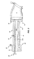
- FIG. 2 shows a schematic three-dimensional side view of a guide system, counterbalance, and transition piece, coupled according to various embodiments of the invention.
- FIG. 3 shows a three-dimensional perspective view of a control arm assembly according to various embodiments of the invention.
- FIG. 1 shows certain features to be more clearly understood in view of FIG. 2 and/or FIG. 3 .
- the gas turbine 2 includes a compressor discharge chamber (CDC) 8, which includes an opening 10 (referred to herein as an "opening", “gas turbine opening” or “opening in the gas turbine”).
- the compressor discharge chamber 8 can be joined with a combustion chamber (not shown) of the gas turbine system 2 by the transition piece (TP) 6. That is, the TP 6 acts as a transition component between the CDC 8 and the downstream combustion chamber.
- the depiction in FIG. 1 shows a snapshot of the apparatus 4 during the installation or removal of the TP 6 from the opening 10 in the gas turbine 2 (particularly, the CDC 8).
- the apparatus 4 can include a control arm assembly 12 ( FIGS. 1 and 3 ) that is sized to rest within the opening 10 in the gas turbine 2.
- the apparatus 4 can further include a guide system 14 ( FIGS. 1 and 2 ) coupled to the control arm assembly 12.
- the guide system 14 is for transporting the TP 6 within the opening 10 in the gas turbine 2.
- the apparatus 4 can include a counter balance 16 coupled to the guide system 14, where the counter balance 16 can counter weight (e.g., a portion of the weight) of the TP 6 during installation and/or removal of the TP 6 from the gas turbine 2.
- the control arm assembly 12 can include a mount 18 for engaging a lip 20 proximate the opening 10 (where the lip 20 can rest at the entry to the opening 10, e.g., partially defining that opening 10).
- the mount 18 is sized to extend within the opening 10, e.g., along an axis (A) of the opening 10.
- the mount 18 includes a first section 22 extending along the axis (A), and a second section 24 which is substantially perpendicular to the first section 22.
- These sections 22, 24 can be formed as a singular unit (e.g., via casting), or may be formed of separate components and later joined (e.g., via welding, brazing or other conventional coupling methods).
- the first section 22 can be longer than the second section 24 in various embodiments. As shown, the second section 24 can rest against the lip 20, and can remain substantially outside of the opening 10 in some cases.
- the control arm assembly 12 can also include a control arm 26, which can be coupled (e.g., mechanically coupled) to the first section 22.
- the control arm 26 can extend substantially perpendicularly from the second section 22, and can be configured to couple to the guide system 14 (e.g., allowing the guide system 14 to rest on the control arm 26).
- the control arm 26 can include a substantially rounded, curved, bowed, or otherwise recessed surface 28 ( FIG. 3 ) for receiving a portion of the guide system 14. It is understood that in various embodiments, the control arm 26 is not fixedly coupled to the guide system 14.
- control arm 26 can be formed of a material with a relatively low coefficient of friction, to allow the control arm 26 to move along the corresponding portion of the guide system 14 to which it is coupled.
- control arm 26 (and the overall control arm assembly 12) can support a portion of the weight of the guide system 14, and consequently, a portion of the weight of the TP 6 (when the TP 6 is coupled to the guide system 14.
- the control arm assembly 12 can include an adjustment member 30 that is configured to be accessible from a location 32 external to the opening 10 in the gas turbine 2. That is, the adjustment member 30 can be accessible from outside of the opening 10 during installation or removal of the TP 6, which allows an operator (e.g., a human operator) to transport the TP 6 within the opening 10 using the apparatus 4 without necessarily needing to reach into the opening 10.
- the adjustment member 30 can include a crank, wheel, ratchet, etc. which can be coupled to a rail system 32 ( FIG. 3 ) for transporting the control arm 26 along the mount 18 e.g., the first section 24 (and in practice, along the axis (A) of the opening 10).
- the rail system 32 can include a mechanical rail system (e.g., a gear-based rail system), a hydraulic rail system (e.g., using a hydraulic pump and cylinders), or any other suitable transport system coupled to the adjustment member 30.
- the guide system 14 when working as the apparatus 4, can rest on the control arm 26 during installation and/or removal of the TP 6 from the opening 10.
- the guide system 14 can have a first end 36 coupled to the TP 6, and a second end 38 opposite the first end 36, the second end 38 coupled to the counter balance 16.
- the first end 36 can include a first mating surface (e.g., a plate) 40 for coupling with the TP 6, where the first mating surface 40 can include one or more conventional mating devices, e.g., clamps, screws, magnetic or suction-based components, etc.
- the first mating surface 40 can include one or more male or female mating members for coupling with portions of the TP 6, e.g., without the need to reach into to opening 10 and perform the coupling.
- the guide system 14 can also include at least one connecting member 42 (several shown) connecting the first end 36 and the second end 38.
- a connecting member 42 can include one or more connecting rods 42A that connect through the first mating surface 40 to the TP 6.
- the connecting rod(s) 42A are used as a slide through the center of the apparatus 4 in such a way as to center the apparatus 4 to the TP 6.
- Rod(s) 42A act as structural members in the guide system 14. Further, the rod(s) 42A attach the counter balance 16 to the first mating surface (plate) 40.
- the connecting member 42 e.g., a steel rod
- the connecting member 42 e.g., rod 42A
- the connecting member 42 can couple with (rest on) the control arm 26, as described herein.
- the second end 38 of the guide system 14 can include a second mating surface 44 (e.g., a plate) for coupling with the counter balance 16.
- the second mating surface 44 can be coupled with the counter balance 16 via one or more fasteners, screws, pins, bolts, etc.
- the counter balance 16 can include a dense metal or other composite which gives it a substantial weight relative to the remainder of the apparatus 4.
- the apparatus 4 can include an additional adjustment member 46 coupled to the counter balance 16 (and the guide system 14) for modifying a position of the weight-shifting mechanism (also called the secondary rigging point) 49 along the guide system 14, e.g., along the rod 42A.
- the additional adjustment member 46 can include one or more of a wheel, crank, ratchet, movable pin, etc. that is connected to the weight-shifting mechanism 49.
- one of the connecting members 42 can include an externally threaded (or notched) rod or other mechanism which can couple to the weight-shifting mechanism 49, e.g., via complimentary threads or notches).
- Rotation of the additional adjustment member 46 can actuate movement of the weight-shifting mechanism 49 to move along the axis A (along the rod 42A). Movement of the weight-shifting mechanism 49 can actuate a change in the center of gravity (CG) of the apparatus. That is, in some cases, the additional adjustment member 46 can be used shift the center of gravity of the apparatus 4, either during installation into the opening 10 or removal from the opening 10, to aid an operator in installation and/or removal of the TP 6.
- CG center of gravity
- the apparatus 4 can also include at least one lifting point 48 (e.g., a hook, flange, etc.) which can be used to engage a lifting device (e.g., a complementary hook, crane, rod, etc., not shown) and aid in lifting the apparatus 4 at least partially into or out of the opening 10.
- a lifting device e.g., a complementary hook, crane, rod, etc., not shown
- the lifting points 48 can be utilized to aid in maneuvering the apparatus 4 (along with the TP 6).
- FIG. 4 shows a process flow diagram illustrating a method according to various embodiments of the invention. These processes can apply to some of the apparatuses and components shown and described with reference to FIGS. 1-3 , however, these processes are not intended to be limited to those particular components shown and described with reference to those Figures. As shown, the method can include:
Landscapes
- Engineering & Computer Science (AREA)
- Mechanical Engineering (AREA)
- General Engineering & Computer Science (AREA)
- Chemical & Material Sciences (AREA)
- Combustion & Propulsion (AREA)
- Structures Of Non-Positive Displacement Pumps (AREA)
- Control Of Turbines (AREA)
- Load-Engaging Elements For Cranes (AREA)
Abstract
Description
- The subject matter disclosed herein relates to power systems. More particularly, the subject matter relates to turbine systems and associated installation/removal apparatuses (or, tools).
- Conventional turbines, such as gas turbines, generally include three sections: a compressor section, a combustor section and a turbine section. In some gas turbine engine designs, a duct, known as a transition piece (or simply, transition), also referred to as a "TP" extends between the combustor section and turbine section. The transition piece (TP) serves many purposes, one of which is to direct the hot gases produced in the combustor section to the turbine section.
- In order to ensure proper operation of the gas turbine engine, the inlet end of the TP and the combustor section should be aligned with precision. However, conventional installation and alignment methods can be cumbersome, time consuming, labor intensive, unsafe, and require manual mathematical calculations. Consequently, rework operations have been common when such conventional methods are employed.
- Various embodiments include an apparatus for installing or removing a transition piece (TP) in a gas turbine, and associated methods. In some cases, the apparatus can include: a control arm assembly sized to rest within an opening in the gas turbine; a guide system coupled to the control arm assembly, the guide system for transporting the TP within the opening in the gas turbine; and a counter balance coupled to the guide system, the counter balance for countering weight of the TP during the installing or the removing of the TP in the gas turbine.
- A first aspect of the invention includes an apparatus for installing or removing a transition piece (TP) in a gas turbine. The apparatus can include: a control arm assembly sized to rest within an opening in the gas turbine; a guide system coupled to the control arm assembly, the guide system for transporting the TP within the opening in the gas turbine; and a counter balance coupled to the guide system, the counter balance for countering weight of the TP during the installing or the removing of the TP in the gas turbine.
- A second aspect of the invention includes an apparatus for installing or removing a transition piece (TP) in a gas turbine. In some cases, the apparatus includes: a control arm assembly sized to rest within an opening in the gas turbine; a guide system coupled to the control arm assembly, the guide system including a first end with a mount for coupling to the TP, and a second end opposing the first end, the guide system for transporting the TP within the opening in the gas turbine; and a counter balance coupled to the second end of the guide system, the counter balance for countering weight of the TP during the installing or the removing of the TP in the gas turbine.
- A third aspect of the invention includes a method including: coupling a transition piece (TP) apparatus with a transition piece (TP), the TP apparatus including: a control arm assembly sized to rest within an opening in the gas turbine; a guide system coupled to the control arm assembly, the guide system for transporting the TP within the opening in the gas turbine; and a counter balance coupled to the guide system; and installing or removing the transition piece from the gas turbine, wherein the counter balance counters weight of the TP during the installing or the removing of the TP in the gas turbine.
- These and other features of this invention will be more readily understood from the following detailed description of the various aspects of the invention taken in conjunction with the accompanying drawings that depict various embodiments of the invention, in which:
-
FIG. 1 shows a schematic cut-away view of a gas turbine along with an apparatus, according to various embodiments of the invention. -
FIG. 2 shows a schematic three-dimensional side view of a guide system section of the apparatus ofFIG. 1 according to various embodiments of the invention. -
FIG. 3 shows a schematic perspective view of an adjustment apparatus of the apparatus ofFIG. 1 according to various embodiments of the invention. -
FIG. 4 shows a flow diagram depicting an illustrative method according to various embodiments of the invention. - It is noted that the drawings of the invention are not necessarily to scale. The drawings are intended to depict only typical aspects of the invention, and therefore should not be considered as limiting the scope of the invention. In the drawings, like numbering represents like elements between the drawings.
- As noted, the subject matter disclosed herein relates to power systems. More particularly, the subject matter relates to turbine systems (e.g., gas turbines) and associated installation/removal apparatuses.
- As described herein, in order to ensure proper operation of the gas turbine engine, the inlet end of the TP and the combustor section should be aligned with precision. However, conventional installation and alignment methods can be cumbersome, time consuming, labor intensive, unsafe, and require manual mathematical calculations. In particular, the significant weight of the TP (approximately 200 pounds) can make installation very difficult. Traditionally, a human operator must reach into the gas turbine engine and place the TP in its desired location using a rail-based system. The operator can have difficulty properly installing the TP due to its weight and the distance it must travel before it can be coupled to the gas turbine engine.
- In contrast to conventional approaches, various embodiments of the invention include an installation apparatus (or, tool) for a gas turbine TP which includes a counter-balance and a control arm. The counter-balance and control arm can be used as rigging (or fulcrum) points when inserting and/or removing the TP from the engine.
- In some cases, the installation tool can include a mating surface (e.g., a round plate) which is designed (sized) to contact a cylindrical forward surface of the TP. This mating surface can act as a bearing surface between the TP and the installation tool. The mating surface (e.g., plate) can be connected to the installation tool's guide system, and together, these elements can be used to transport the TP within an opening in a gas turbine engine. The tool can further include a counter balance (e.g., a head counter weight assembly), which is connected with the mating surface via a rod or tube (e.g., a steel rod or tube). As will be described herein, that counter balance can be used as a secondary rigging point for the tool.
- This rod/tube of the guide system can be centered about the tool and serve as a positioning guide for one of the rigging points. The rod/tube of the guide system can also function as a control arm slide. On a second end of the rod/tube of the guide system, a coupling mechanism (e.g., a plate) can be used to couple the guide system with the counter balance. Once the guide system is coupled to the TP and mounted on the opening of the turbomachine (for either installation or removal of the TP, the counter balance can help to counter the weight of the TP during installation and/or removal.
- Varying the position of the adjustment member (e.g., the acme screw) can actuate movement of a secondary rigging point (also referred to as a slideable weight-shifting mechanism) which can vary the center of gravity (CG) of the tool-TP coupling. That is, movement of the weight-shifting mechanism relative to the rod/tube of the guide system modifies the center of gravity of the joined tool and TP based on where the point lies along the length of the tool.
- In various embodiments, the guide system includes a plurality of connecting members (e.g., rods) that can run the length of the guide system, from the counter balance to the mounting surface, to connect to the mounting features of the TP. The guide system, including these connecting members (rods), allows the tool and the TP to remain in contact throughout the installation/removal process.
- In some embodiments, the weight-shifting mechanism (or, secondary rigging point) can be adjusted by turning an adjustment knob on an upper end of the rod (outside of the opening in the turbomachine). The counter balance can act as a forward end counter weight, and serve as a mounting point for several other features of the tool. That is, the counter balance assembly can act as a forward attachment point during the lifting and installation, or removal. In various embodiments, the counter balance assembly includes at least one swivel eye bolt attachment point. In some cases, the counter balance assembly serves as a mounting point for an acme screw adjustment wheel which is actuatable by an operator (e.g., by turning the wheel) to vary the CG by changing the position of the weight-shifting mechanism.
- In other embodiments, additional features attached to the assembly include an operator's manipulation wheel. This can be a stationary wheel that includes a ring and spokes. The spokes attach the ring to the counter balance assembly and afford the operator mechanical advantage to manipulate the fixture. The control arm slide can be utilized in combination with the control (and support) arm. The control/support arm can be designed to bolt to a compressor discharge (CDC) casing of the gas turbomachine (turbine) at a plurality of locations so the orientation of the control/support arm can be varied depending on the desired angle of entry
- In many cases, the control/support arm is positioned directly below the center point in the vertical direction of the parts as they are installed or removed. This control/support arm can align with the control arm support guide to support the load as the TP is installed or removed. The control/support arm can include an acme screw that can be used to vary the position of the control arm during the installation or removal processes.
- In various embodiments, the tool can include an operator's wheel attached to the acme screw in order to actuate movement of the control arm along the length of the control assembly. The position of the control arm can be varied so that the support point coincides with the secondary rigging point (also referred to as the weight-shifting mechanism) of the TP installation tool. This support arm can be utilized at the half way point of the installation or removal.
- Various particular embodiments of the invention include an apparatus for installing or removing a transition piece (TP) in a gas turbine. The apparatus can include: a control arm assembly sized to rest within an opening in the gas turbine; a guide system coupled to the control arm assembly, the guide system for transporting the TP within the opening in the gas turbine; and a counter balance coupled to the guide system, the counter balance for countering weight of the TP during the installing or the removing of the TP in the gas turbine.
- In various particular embodiments, an apparatus for installing or removing a transition piece (TP) in a gas turbine is disclosed. The apparatus can include: a control arm assembly sized to rest within an opening in the gas turbine; a guide system coupled to the control arm assembly, the guide system for transporting the TP within the opening in the gas turbine; and a counter balance coupled to the guide system, the counter balance for countering weight of the TP during the installing or the removing of the TP in the gas turbine.
- Various other particular embodiments of the invention include an apparatus for installing or removing a transition piece (TP) in a gas turbine. In some cases, the apparatus includes: a control arm assembly sized to rest within an opening in the gas turbine; a guide system coupled to the control arm assembly, the guide system including a first end with a mount for coupling to the TP, and a second end opposing the first end, the guide system for transporting the TP within the opening in the gas turbine; and a counter balance coupled to the second end of the guide system, the counter balance for countering weight of the TP during the installing or the removing of the TP in the gas turbine.
- Various additional embodiments of the invention include a method, e.g., a method of installing and/or removing a TP from a gas turbine. In some cases, the method can include: coupling a transition piece (TP) apparatus with a transition piece (TP), the TP apparatus including: a control arm assembly sized to rest within an opening in the gas turbine; a guide system coupled to the control arm assembly, the guide system for transporting the TP within the opening in the gas turbine; and a counter balance coupled to the guide system; and installing or removing the transition piece from the gas turbine, wherein the counter balance counters weight of the TP during the installing or the removing of the TP in the gas turbine.
- Turning to
FIG. 1 , a schematic cut-away view of a portion of a gas turbine 2 along with an apparatus 4 for installing or removing a transition piece (TP) 6 is shown according to various embodiments of the invention.FIG. 2 shows a schematic three-dimensional side view of a guide system, counterbalance, and transition piece, coupled according to various embodiments of the invention.FIG. 3 shows a three-dimensional perspective view of a control arm assembly according to various embodiments of the invention. In describing various embodiments of the invention, reference is made primarily toFIG. 1 , however certain features will be more clearly understood in view ofFIG. 2 and/orFIG. 3 . - Returning to
FIG. 1 , as is known in the art, the gas turbine 2 includes a compressor discharge chamber (CDC) 8, which includes an opening 10 (referred to herein as an "opening", "gas turbine opening" or "opening in the gas turbine"). As is further known in the art, thecompressor discharge chamber 8 can be joined with a combustion chamber (not shown) of the gas turbine system 2 by the transition piece (TP) 6. That is, theTP 6 acts as a transition component between theCDC 8 and the downstream combustion chamber. The depiction inFIG. 1 shows a snapshot of the apparatus 4 during the installation or removal of theTP 6 from theopening 10 in the gas turbine 2 (particularly, the CDC 8). - As shown, the apparatus 4 can include a control arm assembly 12 (
FIGS. 1 and3 ) that is sized to rest within theopening 10 in the gas turbine 2. The apparatus 4 can further include a guide system 14 (FIGS. 1 and2 ) coupled to thecontrol arm assembly 12. Theguide system 14 is for transporting theTP 6 within theopening 10 in the gas turbine 2. Also shown, the apparatus 4 can include acounter balance 16 coupled to theguide system 14, where thecounter balance 16 can counter weight (e.g., a portion of the weight) of theTP 6 during installation and/or removal of theTP 6 from the gas turbine 2. - In more particular detail, the control arm assembly 12 (also shown in
FIG. 3 ) can include amount 18 for engaging alip 20 proximate the opening 10 (where thelip 20 can rest at the entry to theopening 10, e.g., partially defining that opening 10). In some cases, themount 18 is sized to extend within theopening 10, e.g., along an axis (A) of theopening 10. In various embodiments, themount 18 includes afirst section 22 extending along the axis (A), and asecond section 24 which is substantially perpendicular to thefirst section 22. Thesesections first section 22 can be longer than thesecond section 24 in various embodiments. As shown, thesecond section 24 can rest against thelip 20, and can remain substantially outside of theopening 10 in some cases. - The
control arm assembly 12 can also include acontrol arm 26, which can be coupled (e.g., mechanically coupled) to thefirst section 22. Thecontrol arm 26 can extend substantially perpendicularly from thesecond section 22, and can be configured to couple to the guide system 14 (e.g., allowing theguide system 14 to rest on the control arm 26). Thecontrol arm 26 can include a substantially rounded, curved, bowed, or otherwise recessed surface 28 (FIG. 3 ) for receiving a portion of theguide system 14. It is understood that in various embodiments, thecontrol arm 26 is not fixedly coupled to theguide system 14. Further, thesurface 28 of thecontrol arm 26 can be formed of a material with a relatively low coefficient of friction, to allow thecontrol arm 26 to move along the corresponding portion of theguide system 14 to which it is coupled. As described herein, the control arm 26 (and the overall control arm assembly 12) can support a portion of the weight of theguide system 14, and consequently, a portion of the weight of the TP 6 (when theTP 6 is coupled to theguide system 14. - Also shown in
FIGS. 1 and3 , thecontrol arm assembly 12 can include anadjustment member 30 that is configured to be accessible from alocation 32 external to theopening 10 in the gas turbine 2. That is, theadjustment member 30 can be accessible from outside of theopening 10 during installation or removal of theTP 6, which allows an operator (e.g., a human operator) to transport theTP 6 within theopening 10 using the apparatus 4 without necessarily needing to reach into theopening 10. Shown more particularly inFIG. 3 , theadjustment member 30 can include a crank, wheel, ratchet, etc. which can be coupled to a rail system 32 (FIG. 3 ) for transporting thecontrol arm 26 along themount 18 e.g., the first section 24 (and in practice, along the axis (A) of the opening 10). Therail system 32 can include a mechanical rail system (e.g., a gear-based rail system), a hydraulic rail system (e.g., using a hydraulic pump and cylinders), or any other suitable transport system coupled to theadjustment member 30. - Returning to
FIG. 1 (and with reference toFIG. 2 ), when working as the apparatus 4, theguide system 14 can rest on thecontrol arm 26 during installation and/or removal of theTP 6 from theopening 10. As shown, theguide system 14 can have afirst end 36 coupled to theTP 6, and asecond end 38 opposite thefirst end 36, thesecond end 38 coupled to thecounter balance 16. Thefirst end 36 can include a first mating surface (e.g., a plate) 40 for coupling with theTP 6, where thefirst mating surface 40 can include one or more conventional mating devices, e.g., clamps, screws, magnetic or suction-based components, etc. In some cases, thefirst mating surface 40 can include one or more male or female mating members for coupling with portions of theTP 6, e.g., without the need to reach into to opening 10 and perform the coupling. - The
guide system 14 can also include at least one connecting member 42 (several shown) connecting thefirst end 36 and thesecond end 38. In some embodiments, a connectingmember 42 can include one or moreconnecting rods 42A that connect through thefirst mating surface 40 to theTP 6. The connecting rod(s) 42A are used as a slide through the center of the apparatus 4 in such a way as to center the apparatus 4 to theTP 6. Rod(s) 42A act as structural members in theguide system 14. Further, the rod(s) 42A attach thecounter balance 16 to the first mating surface (plate) 40. The connecting member 42 (e.g., a steel rod) can span from thefirst end 36 to thesecond end 38 of theguide system 14. In various embodiments, the connecting member 42 (e.g.,rod 42A) can couple with (rest on) thecontrol arm 26, as described herein. - The
second end 38 of theguide system 14 can include a second mating surface 44 (e.g., a plate) for coupling with thecounter balance 16. Thesecond mating surface 44 can be coupled with thecounter balance 16 via one or more fasteners, screws, pins, bolts, etc. In some cases, thecounter balance 16 can include a dense metal or other composite which gives it a substantial weight relative to the remainder of the apparatus 4. - Returning to
FIG. 1 , in some cases, the apparatus 4 can include anadditional adjustment member 46 coupled to the counter balance 16 (and the guide system 14) for modifying a position of the weight-shifting mechanism (also called the secondary rigging point) 49 along theguide system 14, e.g., along therod 42A. Theadditional adjustment member 46 can include one or more of a wheel, crank, ratchet, movable pin, etc. that is connected to the weight-shiftingmechanism 49. In some cases, (shown inFIG. 2 ), one of the connectingmembers 42 can include an externally threaded (or notched) rod or other mechanism which can couple to the weight-shiftingmechanism 49, e.g., via complimentary threads or notches). Rotation of theadditional adjustment member 46 can actuate movement of the weight-shiftingmechanism 49 to move along the axis A (along therod 42A). Movement of the weight-shiftingmechanism 49 can actuate a change in the center of gravity (CG) of the apparatus. That is, in some cases, theadditional adjustment member 46 can be used shift the center of gravity of the apparatus 4, either during installation into theopening 10 or removal from theopening 10, to aid an operator in installation and/or removal of theTP 6. - The apparatus 4 can also include at least one lifting point 48 (e.g., a hook, flange, etc.) which can be used to engage a lifting device (e.g., a complementary hook, crane, rod, etc., not shown) and aid in lifting the apparatus 4 at least partially into or out of the
opening 10. Because the apparatus 4 includes a substantial amount of weight (particularly in the counter balance 16), and theTP 6 can weigh approximately 200 pounds (lbs), there may be times during installation and/or removal of theTP 6 using the apparatus 4 where additional lifting is beneficial. In these circumstances, the lifting points 48 can be utilized to aid in maneuvering the apparatus 4 (along with the TP 6). -
FIG. 4 shows a process flow diagram illustrating a method according to various embodiments of the invention. These processes can apply to some of the apparatuses and components shown and described with reference toFIGS. 1-3 , however, these processes are not intended to be limited to those particular components shown and described with reference to those Figures. As shown, the method can include: - Process P1: coupling a transition piece (TP) apparatus with a transition piece TP. In some cases, the apparatus can include: a control arm assembly sized to rest within an opening in the gas turbine; a guide system coupled to the control arm assembly, the guide system for transporting the TP within the opening in the gas turbine; and a counter balance coupled to the guide system; and
- Process P2: installing or removing the transition piece from the gas turbine, wherein the counter balance counters weight of the TP during the installing or the removing of the TP in the gas turbine. In some cases, process P2 can include one or both of the following sub-processes:
- Process P2A: adjusting a center of gravity of the coupled TP apparatus and TP during the installing or the removing; and/or
- Process P2B: engaging the control arm with a lip portion of the opening in the gas turbine during the installing or the removing.
- The terminology used herein is for the purpose of describing particular embodiments only and is not intended to be limiting of the disclosure. As used herein, the singular forms "a", "an" and "the" are intended to include the plural forms as well, unless the context clearly indicates otherwise. It will be further understood that the terms "comprises" and/or "comprising," when used in this specification, specify the presence of stated features, integers, steps, operations, elements, and/or components, but do not preclude the presence or addition of one or more other features, integers, steps, operations, elements, components, and/or groups thereof. It is further understood that the terms "front" and "back" are not intended to be limiting and are intended to be interchangeable where appropriate.
- This written description uses examples to disclose the invention, including the best mode, and also to enable any person skilled in the art to practice the invention, including making and using any devices or systems and performing any incorporated methods. The patentable scope of the invention is defined by the claims, and may include other examples that occur to those skilled in the art. Such other examples are intended to be within the scope of the claims if they have structural elements that do not differ from the literal language of the claims, or if they include equivalent structural elements with insubstantial differences from the literal languages of the claims.
- Various aspects and embodiments of the present invention are defined by the following numbered clauses:
- 1. An apparatus for installing or removing a transition piece (TP) in a gas turbine, the apparatus comprising:
- a control arm assembly sized to rest within an opening in the gas turbine;
- a guide system coupled to the control arm assembly, the guide system for transporting the TP within the opening in the gas turbine; and
- a counter balance coupled to the guide system, the counter balance for countering weight of the TP during the installing or the removing of the TP in the gas turbine.
- 2. The apparatus of clause 1, further comprising a first adjustment member coupled to the counter balance and the guide system for adjusting a center of gravity of the apparatus along a primary axis of the guide system..
- 3. The apparatus of any preceding clause, wherein the guide system is coupled to the counter balance at a first end of the guide system, and wherein the guide system is configured to couple to the TP at an opposite end of the guide system.
- 4. The apparatus of any preceding clause, wherein the control arm assembly includes an adjustment member configured to be accessible from a location external to the opening in the gas turbine.
- 5. The apparatus of any preceding clause, wherein the control arm assembly includes a mount for engaging a lip proximate the opening in the gas turbine.
- 6. The apparatus of any preceding clause, wherein the mount is sized to extend within the opening along an axis of the opening.
- 7. The apparatus of any preceding clause, wherein the control arm assembly further includes a control arm coupled to the guide system, the control arm for supporting a portion of a weight of the guide system and a portion of the weight of the TP.
- 8. The apparatus of any preceding clause, further comprising a second adjustment member coupled to the control arm assembly for modifying a position of the control arm along the mount.
- 9. An apparatus for installing or removing a transition piece (TP) in a gas turbine, the apparatus comprising:
- a control arm assembly sized to rest within an opening in the gas turbine;
- a guide system coupled to the control arm assembly, the guide system including a first end with a mount for coupling to the TP, and a second end opposing the first end, the guide system for transporting the TP within the opening in the gas turbine; and
- a counter balance coupled to the second end of the guide system, the counter balance for countering weight of the TP during the installing or the removing of the TP in the gas turbine.
- 10. The apparatus of any preceding clause, further comprising a first adjustment member coupled to the counter balance and the guide system for varying a center of gravity of the apparatus along a primary axis of the guide system from a position outside of the opening in the gas turbine.
- 11. The apparatus of any preceding clause, wherein the control arm assembly includes an adjustment member configured to be accessible from a location external to the opening in the gas turbine.
- 12. The apparatus of any preceding clause, wherein the control arm assembly includes a mount for engaging a lip proximate the opening in the gas turbine.
- 13. The apparatus of any preceding clause, wherein the mount is sized to extend within the opening along an axis of the opening.
- 14. The apparatus of any preceding clause, wherein the control arm assembly further includes a control arm coupled to the guide system, the control arm for supporting a portion of a weight of the guide system and a portion of the weight of the TP.
- 15. The apparatus of any preceding clause, further comprising a second adjustment member coupled to the control arm assembly for modifying a position of the control arm along the mount.
- 16. The apparatus of any preceding clause, further comprising at least one lifting point for receiving a lifting member during the installing or the removing of the TP in the gas turbine.
- 17. A method comprising:
- coupling a transition piece (TP) apparatus with a transition piece (TP), the TP apparatus including:
- a control arm assembly sized to rest within an opening in the gas turbine;
- a guide system coupled to the control arm assembly, the guide system for transporting the TP within the opening in the gas turbine; and
- a counter balance coupled to the guide system; and
- installing or removing the TP from the gas turbine, wherein the counter balance counters weight of the TP during the installing or the removing of the TP in the gas turbine.
- coupling a transition piece (TP) apparatus with a transition piece (TP), the TP apparatus including:
- 18. The method of any preceding clause, wherein the installing or removing further includes adjusting a center of gravity of the coupled TP apparatus and TP during the installing or the removing.
- 19. The method of any preceding clause, further comprising engaging a lip proximate the opening in the gas turbine with the control arm during the installing or the removing.
Claims (14)
- An apparatus (4) for installing or removing a transition piece (TP) (6) in a gas turbine (2), the apparatus comprising:a control arm assembly (12) sized to rest within an opening (10) in the gas turbine (2);a guide system (14) coupled to the control arm assembly (12), the guide system (14) for transporting the TP (6) within the opening (10) in the gas turbine (2); anda counter balance (16) coupled to the guide system (40), the counter balance (16) for countering weight of the TP (6) during the installing or the removing of the TP (6) in the gas turbine (2).
- The apparatus of claim 1, further comprising a first adjustment member (30) coupled to the counter balance (16) and the guide system (14) for adjusting a center of gravity of the apparatus along a primary axis of the guide system (14).
- The apparatus of claim 2, wherein the guide system (14) is coupled to the counter balance (16) at a first end of the guide system, and wherein the guide system is configured to couple to the TP (6) at an opposite end of the guide system (14).
- The apparatus of claim 1, wherein:the guide system (14) includes a first end (36) with a mount for coupling to the TP (6), and a second end (38) opposing the first end (36); andthe counter balance (16) is coupled to the second end (38) of the guide system (14).
- The apparatus of claim 4, further comprising a first adjustment member (30) coupled to the counter balance (16) and the guide system (14) for varying a center of gravity of the apparatus along a primary axis of the guide system (14) from a position outside of the opening (10) in the gas turbine (2).
- The apparatus of claim 4 or claim 5, further comprising at least one lifting point (48) for receiving a lifting member during the installing or the removing of the TP (6) in the gas turbine (2).
- The apparatus of any preceding claim, wherein the control arm assembly (12) includes an adjustment member configured to be accessible from a location external to the opening (10) in the gas turbine (2).
- The apparatus of any preceding claim, wherein the control arm assembly (12) includes a mount (18) for engaging a lip (20) proximate the opening (10) in the gas turbine (2).
- The apparatus of claim 8, wherein the mount (18) is sized to extend within the opening (10) along an axis of the opening.
- The apparatus of claim 9, wherein the control arm assembly (12) further includes a control arm (26) coupled to the guide system (14), the control arm (26) for supporting a portion of a weight of the guide system (14) and a portion of the weight of the TP (6).
- The apparatus of claim 10, further comprising a second adjustment member (46) coupled to the control arm assembly (12) for modifying a position of the control arm (26) along the mount (18).
- A method comprising:coupling (P1) a transition piece (TP) apparatus with a transition piece (TP), the TP apparatus including:a control arm assembly sized to rest within an opening in the gas turbine;a guide system coupled to the control arm assembly, the guide system for transporting the TP within the opening in the gas turbine; anda counter balance coupled to the guide system; andinstalling or removing (P2) the TP from the gas turbine, wherein the counter balance counters weight of the TP during the installing or the removing of the TP in the gas turbine.
- The method of claim 12, wherein the installing or removing (P2) further includes adjusting a center of gravity of the coupled TP apparatus and TP during the installing or the removing.
- The method of claim 12 or claim 13, further comprising engaging (P2B) a lip proximate the opening in the gas turbine with the control arm during the installing or the removing.
Applications Claiming Priority (1)
| Application Number | Priority Date | Filing Date | Title |
|---|---|---|---|
| US13/714,856 US9144866B2 (en) | 2012-12-14 | 2012-12-14 | Turbine transition piece (TP) apparatus and method |
Publications (3)
| Publication Number | Publication Date |
|---|---|
| EP2743458A2 true EP2743458A2 (en) | 2014-06-18 |
| EP2743458A3 EP2743458A3 (en) | 2017-06-21 |
| EP2743458B1 EP2743458B1 (en) | 2019-02-27 |
Family
ID=49759072
Family Applications (1)
| Application Number | Title | Priority Date | Filing Date |
|---|---|---|---|
| EP13196194.8A Active EP2743458B1 (en) | 2012-12-14 | 2013-12-09 | Apparatus and method for installing and removing a turbine transition piece |
Country Status (2)
| Country | Link |
|---|---|
| US (1) | US9144866B2 (en) |
| EP (1) | EP2743458B1 (en) |
Cited By (2)
| Publication number | Priority date | Publication date | Assignee | Title |
|---|---|---|---|---|
| US20140360193A1 (en) * | 2013-03-18 | 2014-12-11 | General Electric Company | Support frame and method for assembly of a combustion module of a gas turbine |
| EP3088691A1 (en) * | 2015-04-27 | 2016-11-02 | General Electric Technology GmbH | Gas turbine disassembly method |
Families Citing this family (4)
| Publication number | Priority date | Publication date | Assignee | Title |
|---|---|---|---|---|
| CN105082047B (en) * | 2015-08-29 | 2017-04-12 | 深圳市强瑞电子有限公司 | Screen TP detaching mechanism |
| CN105397465B (en) * | 2015-12-08 | 2017-05-31 | 四川成发航空科技股份有限公司 | For the device of engine turbine assembling |
| WO2017116244A1 (en) * | 2015-12-31 | 2017-07-06 | General Electric Company | Combustor assembly lift systems and methods for using the same to install and remove combustor assemblies |
| EP3354985B1 (en) * | 2017-01-27 | 2020-11-25 | General Electric Company | Combustion can maintenance apparatus and method |
Family Cites Families (6)
| Publication number | Priority date | Publication date | Assignee | Title |
|---|---|---|---|---|
| JP2877296B2 (en) | 1995-09-11 | 1999-03-31 | 三菱重工業株式会社 | Gas turbine combustor installation and removal equipment |
| GB2306155B (en) | 1995-10-11 | 1997-11-19 | Toshiba Kk | Apparatus and method for disassembling and assembling gas turbine combuster |
| US5921075A (en) * | 1995-10-19 | 1999-07-13 | Mitsubishi Jukogyo Kabushiki Kaisha | Burner replacing system |
| EP2236939A1 (en) * | 2009-03-27 | 2010-10-06 | Siemens Aktiengesellschaft | Device for assembling and disassembling a component of a gas turbine |
| JP5495687B2 (en) * | 2009-09-16 | 2014-05-21 | 三菱重工業株式会社 | Combustor tail tube detachable jig and combustor tail tube assembly method |
| KR101219884B1 (en) * | 2011-03-14 | 2013-01-09 | 한전케이피에스 주식회사 | Transition piece holding device |
-
2012
- 2012-12-14 US US13/714,856 patent/US9144866B2/en active Active
-
2013
- 2013-12-09 EP EP13196194.8A patent/EP2743458B1/en active Active
Non-Patent Citations (1)
| Title |
|---|
| None |
Cited By (4)
| Publication number | Priority date | Publication date | Assignee | Title |
|---|---|---|---|---|
| US20140360193A1 (en) * | 2013-03-18 | 2014-12-11 | General Electric Company | Support frame and method for assembly of a combustion module of a gas turbine |
| US9631812B2 (en) * | 2013-03-18 | 2017-04-25 | General Electric Company | Support frame and method for assembly of a combustion module of a gas turbine |
| EP3088691A1 (en) * | 2015-04-27 | 2016-11-02 | General Electric Technology GmbH | Gas turbine disassembly method |
| US10428737B2 (en) | 2015-04-27 | 2019-10-01 | Ansaldo Energia Switzerland AG | Gas turbine disassembly method |
Also Published As
| Publication number | Publication date |
|---|---|
| EP2743458A3 (en) | 2017-06-21 |
| EP2743458B1 (en) | 2019-02-27 |
| US9144866B2 (en) | 2015-09-29 |
| US20140165397A1 (en) | 2014-06-19 |
Similar Documents
| Publication | Publication Date | Title |
|---|---|---|
| EP2743458A2 (en) | Apparatus and method for installing and removing a turbine transition piece | |
| EP3106756B1 (en) | Combustion flow sleeve lifting tool | |
| JP7034665B2 (en) | Installing or removing turbine blades at the base of the turbine blades | |
| EP2565379A2 (en) | System and method for modifying a rotor | |
| US20110247193A1 (en) | Apparatus And Method For Installing Combustion Liners | |
| CN102826441B (en) | System and method for adjusting shroud block in casing | |
| US8984730B2 (en) | System and method for rotating a turbine shell | |
| EP3225779A1 (en) | Removal tool | |
| US9896973B2 (en) | Assembly tool for exhaust turbochargers | |
| US20150337685A1 (en) | Method and device for mounting and removing a turbine component | |
| US11022147B2 (en) | Inlet guide vane removal tools and methods | |
| US10519810B2 (en) | Manipulation of turbomachine combustors | |
| US8910374B2 (en) | Service apparatus for turbomachine | |
| CN107795380B (en) | Method and apparatus for mounting and handling a combustor mounted in a turbine casing | |
| US10533751B2 (en) | Combustion can maintenance apparatus and method | |
| EP2743457A2 (en) | Turbine transition piece alignment apparatus and method | |
| CN224144535U (en) | Special tool for dismounting and mounting manhole door of steam drum | |
| CN218235812U (en) | Automatic change aluminum product cutting precision axle for transmission | |
| US20180080574A1 (en) | Manufacture of actuators and control valve assemblies | |
| HK1234804A1 (en) | Disassembly method for gas turbines and calibration device |
Legal Events
| Date | Code | Title | Description |
|---|---|---|---|
| PUAI | Public reference made under article 153(3) epc to a published international application that has entered the european phase |
Free format text: ORIGINAL CODE: 0009012 |
|
| 17P | Request for examination filed |
Effective date: 20131209 |
|
| AK | Designated contracting states |
Kind code of ref document: A2 Designated state(s): AL AT BE BG CH CY CZ DE DK EE ES FI FR GB GR HR HU IE IS IT LI LT LU LV MC MK MT NL NO PL PT RO RS SE SI SK SM TR |
|
| AX | Request for extension of the european patent |
Extension state: BA ME |
|
| PUAL | Search report despatched |
Free format text: ORIGINAL CODE: 0009013 |
|
| AK | Designated contracting states |
Kind code of ref document: A3 Designated state(s): AL AT BE BG CH CY CZ DE DK EE ES FI FR GB GR HR HU IE IS IT LI LT LU LV MC MK MT NL NO PL PT RO RS SE SI SK SM TR |
|
| AX | Request for extension of the european patent |
Extension state: BA ME |
|
| RIC1 | Information provided on ipc code assigned before grant |
Ipc: F01D 9/02 20060101AFI20170518BHEP Ipc: F01D 25/28 20060101ALI20170518BHEP Ipc: F23R 3/60 20060101ALI20170518BHEP |
|
| STAA | Information on the status of an ep patent application or granted ep patent |
Free format text: STATUS: REQUEST FOR EXAMINATION WAS MADE |
|
| STAA | Information on the status of an ep patent application or granted ep patent |
Free format text: STATUS: EXAMINATION IS IN PROGRESS |
|
| R17P | Request for examination filed (corrected) |
Effective date: 20171221 |
|
| RBV | Designated contracting states (corrected) |
Designated state(s): AL AT BE BG CH CY CZ DE DK EE ES FI FR GB GR HR HU IE IS IT LI LT LU LV MC MK MT NL NO PL PT RO RS SE SI SK SM TR |
|
| 17Q | First examination report despatched |
Effective date: 20180206 |
|
| GRAP | Despatch of communication of intention to grant a patent |
Free format text: ORIGINAL CODE: EPIDOSNIGR1 |
|
| STAA | Information on the status of an ep patent application or granted ep patent |
Free format text: STATUS: GRANT OF PATENT IS INTENDED |
|
| INTG | Intention to grant announced |
Effective date: 20180927 |
|
| GRAS | Grant fee paid |
Free format text: ORIGINAL CODE: EPIDOSNIGR3 |
|
| GRAA | (expected) grant |
Free format text: ORIGINAL CODE: 0009210 |
|
| STAA | Information on the status of an ep patent application or granted ep patent |
Free format text: STATUS: THE PATENT HAS BEEN GRANTED |
|
| AK | Designated contracting states |
Kind code of ref document: B1 Designated state(s): AL AT BE BG CH CY CZ DE DK EE ES FI FR GB GR HR HU IE IS IT LI LT LU LV MC MK MT NL NO PL PT RO RS SE SI SK SM TR |
|
| REG | Reference to a national code |
Ref country code: GB Ref legal event code: FG4D |
|
| REG | Reference to a national code |
Ref country code: CH Ref legal event code: EP |
|
| REG | Reference to a national code |
Ref country code: DE Ref legal event code: R096 Ref document number: 602013051346 Country of ref document: DE |
|
| REG | Reference to a national code |
Ref country code: AT Ref legal event code: REF Ref document number: 1101638 Country of ref document: AT Kind code of ref document: T Effective date: 20190315 |
|
| REG | Reference to a national code |
Ref country code: IE Ref legal event code: FG4D |
|
| REG | Reference to a national code |
Ref country code: NL Ref legal event code: MP Effective date: 20190227 |
|
| REG | Reference to a national code |
Ref country code: LT Ref legal event code: MG4D |
|
| PG25 | Lapsed in a contracting state [announced via postgrant information from national office to epo] |
Ref country code: NL Free format text: LAPSE BECAUSE OF FAILURE TO SUBMIT A TRANSLATION OF THE DESCRIPTION OR TO PAY THE FEE WITHIN THE PRESCRIBED TIME-LIMIT Effective date: 20190227 Ref country code: LT Free format text: LAPSE BECAUSE OF FAILURE TO SUBMIT A TRANSLATION OF THE DESCRIPTION OR TO PAY THE FEE WITHIN THE PRESCRIBED TIME-LIMIT Effective date: 20190227 Ref country code: FI Free format text: LAPSE BECAUSE OF FAILURE TO SUBMIT A TRANSLATION OF THE DESCRIPTION OR TO PAY THE FEE WITHIN THE PRESCRIBED TIME-LIMIT Effective date: 20190227 Ref country code: PT Free format text: LAPSE BECAUSE OF FAILURE TO SUBMIT A TRANSLATION OF THE DESCRIPTION OR TO PAY THE FEE WITHIN THE PRESCRIBED TIME-LIMIT Effective date: 20190627 Ref country code: NO Free format text: LAPSE BECAUSE OF FAILURE TO SUBMIT A TRANSLATION OF THE DESCRIPTION OR TO PAY THE FEE WITHIN THE PRESCRIBED TIME-LIMIT Effective date: 20190527 Ref country code: SE Free format text: LAPSE BECAUSE OF FAILURE TO SUBMIT A TRANSLATION OF THE DESCRIPTION OR TO PAY THE FEE WITHIN THE PRESCRIBED TIME-LIMIT Effective date: 20190227 |
|
| PG25 | Lapsed in a contracting state [announced via postgrant information from national office to epo] |
Ref country code: HR Free format text: LAPSE BECAUSE OF FAILURE TO SUBMIT A TRANSLATION OF THE DESCRIPTION OR TO PAY THE FEE WITHIN THE PRESCRIBED TIME-LIMIT Effective date: 20190227 Ref country code: RS Free format text: LAPSE BECAUSE OF FAILURE TO SUBMIT A TRANSLATION OF THE DESCRIPTION OR TO PAY THE FEE WITHIN THE PRESCRIBED TIME-LIMIT Effective date: 20190227 Ref country code: BG Free format text: LAPSE BECAUSE OF FAILURE TO SUBMIT A TRANSLATION OF THE DESCRIPTION OR TO PAY THE FEE WITHIN THE PRESCRIBED TIME-LIMIT Effective date: 20190527 Ref country code: GR Free format text: LAPSE BECAUSE OF FAILURE TO SUBMIT A TRANSLATION OF THE DESCRIPTION OR TO PAY THE FEE WITHIN THE PRESCRIBED TIME-LIMIT Effective date: 20190528 Ref country code: IS Free format text: LAPSE BECAUSE OF FAILURE TO SUBMIT A TRANSLATION OF THE DESCRIPTION OR TO PAY THE FEE WITHIN THE PRESCRIBED TIME-LIMIT Effective date: 20190627 Ref country code: LV Free format text: LAPSE BECAUSE OF FAILURE TO SUBMIT A TRANSLATION OF THE DESCRIPTION OR TO PAY THE FEE WITHIN THE PRESCRIBED TIME-LIMIT Effective date: 20190227 |
|
| REG | Reference to a national code |
Ref country code: AT Ref legal event code: MK05 Ref document number: 1101638 Country of ref document: AT Kind code of ref document: T Effective date: 20190227 |
|
| PG25 | Lapsed in a contracting state [announced via postgrant information from national office to epo] |
Ref country code: AL Free format text: LAPSE BECAUSE OF FAILURE TO SUBMIT A TRANSLATION OF THE DESCRIPTION OR TO PAY THE FEE WITHIN THE PRESCRIBED TIME-LIMIT Effective date: 20190227 Ref country code: DK Free format text: LAPSE BECAUSE OF FAILURE TO SUBMIT A TRANSLATION OF THE DESCRIPTION OR TO PAY THE FEE WITHIN THE PRESCRIBED TIME-LIMIT Effective date: 20190227 Ref country code: IT Free format text: LAPSE BECAUSE OF FAILURE TO SUBMIT A TRANSLATION OF THE DESCRIPTION OR TO PAY THE FEE WITHIN THE PRESCRIBED TIME-LIMIT Effective date: 20190227 Ref country code: SK Free format text: LAPSE BECAUSE OF FAILURE TO SUBMIT A TRANSLATION OF THE DESCRIPTION OR TO PAY THE FEE WITHIN THE PRESCRIBED TIME-LIMIT Effective date: 20190227 Ref country code: EE Free format text: LAPSE BECAUSE OF FAILURE TO SUBMIT A TRANSLATION OF THE DESCRIPTION OR TO PAY THE FEE WITHIN THE PRESCRIBED TIME-LIMIT Effective date: 20190227 Ref country code: RO Free format text: LAPSE BECAUSE OF FAILURE TO SUBMIT A TRANSLATION OF THE DESCRIPTION OR TO PAY THE FEE WITHIN THE PRESCRIBED TIME-LIMIT Effective date: 20190227 Ref country code: CZ Free format text: LAPSE BECAUSE OF FAILURE TO SUBMIT A TRANSLATION OF THE DESCRIPTION OR TO PAY THE FEE WITHIN THE PRESCRIBED TIME-LIMIT Effective date: 20190227 Ref country code: ES Free format text: LAPSE BECAUSE OF FAILURE TO SUBMIT A TRANSLATION OF THE DESCRIPTION OR TO PAY THE FEE WITHIN THE PRESCRIBED TIME-LIMIT Effective date: 20190227 |
|
| REG | Reference to a national code |
Ref country code: DE Ref legal event code: R097 Ref document number: 602013051346 Country of ref document: DE |
|
| PG25 | Lapsed in a contracting state [announced via postgrant information from national office to epo] |
Ref country code: PL Free format text: LAPSE BECAUSE OF FAILURE TO SUBMIT A TRANSLATION OF THE DESCRIPTION OR TO PAY THE FEE WITHIN THE PRESCRIBED TIME-LIMIT Effective date: 20190227 Ref country code: SM Free format text: LAPSE BECAUSE OF FAILURE TO SUBMIT A TRANSLATION OF THE DESCRIPTION OR TO PAY THE FEE WITHIN THE PRESCRIBED TIME-LIMIT Effective date: 20190227 |
|
| PG25 | Lapsed in a contracting state [announced via postgrant information from national office to epo] |
Ref country code: AT Free format text: LAPSE BECAUSE OF FAILURE TO SUBMIT A TRANSLATION OF THE DESCRIPTION OR TO PAY THE FEE WITHIN THE PRESCRIBED TIME-LIMIT Effective date: 20190227 |
|
| PLBE | No opposition filed within time limit |
Free format text: ORIGINAL CODE: 0009261 |
|
| STAA | Information on the status of an ep patent application or granted ep patent |
Free format text: STATUS: NO OPPOSITION FILED WITHIN TIME LIMIT |
|
| 26N | No opposition filed |
Effective date: 20191128 |
|
| PG25 | Lapsed in a contracting state [announced via postgrant information from national office to epo] |
Ref country code: SI Free format text: LAPSE BECAUSE OF FAILURE TO SUBMIT A TRANSLATION OF THE DESCRIPTION OR TO PAY THE FEE WITHIN THE PRESCRIBED TIME-LIMIT Effective date: 20190227 |
|
| PG25 | Lapsed in a contracting state [announced via postgrant information from national office to epo] |
Ref country code: TR Free format text: LAPSE BECAUSE OF FAILURE TO SUBMIT A TRANSLATION OF THE DESCRIPTION OR TO PAY THE FEE WITHIN THE PRESCRIBED TIME-LIMIT Effective date: 20190227 |
|
| REG | Reference to a national code |
Ref country code: CH Ref legal event code: PL |
|
| REG | Reference to a national code |
Ref country code: BE Ref legal event code: MM Effective date: 20191231 |
|
| PG25 | Lapsed in a contracting state [announced via postgrant information from national office to epo] |
Ref country code: MC Free format text: LAPSE BECAUSE OF FAILURE TO SUBMIT A TRANSLATION OF THE DESCRIPTION OR TO PAY THE FEE WITHIN THE PRESCRIBED TIME-LIMIT Effective date: 20190227 |
|
| GBPC | Gb: european patent ceased through non-payment of renewal fee |
Effective date: 20191209 |
|
| PG25 | Lapsed in a contracting state [announced via postgrant information from national office to epo] |
Ref country code: GB Free format text: LAPSE BECAUSE OF NON-PAYMENT OF DUE FEES Effective date: 20191209 Ref country code: IE Free format text: LAPSE BECAUSE OF NON-PAYMENT OF DUE FEES Effective date: 20191209 Ref country code: LU Free format text: LAPSE BECAUSE OF NON-PAYMENT OF DUE FEES Effective date: 20191209 |
|
| PG25 | Lapsed in a contracting state [announced via postgrant information from national office to epo] |
Ref country code: CH Free format text: LAPSE BECAUSE OF NON-PAYMENT OF DUE FEES Effective date: 20191231 Ref country code: LI Free format text: LAPSE BECAUSE OF NON-PAYMENT OF DUE FEES Effective date: 20191231 Ref country code: BE Free format text: LAPSE BECAUSE OF NON-PAYMENT OF DUE FEES Effective date: 20191231 |
|
| PG25 | Lapsed in a contracting state [announced via postgrant information from national office to epo] |
Ref country code: CY Free format text: LAPSE BECAUSE OF FAILURE TO SUBMIT A TRANSLATION OF THE DESCRIPTION OR TO PAY THE FEE WITHIN THE PRESCRIBED TIME-LIMIT Effective date: 20190227 |
|
| PG25 | Lapsed in a contracting state [announced via postgrant information from national office to epo] |
Ref country code: HU Free format text: LAPSE BECAUSE OF FAILURE TO SUBMIT A TRANSLATION OF THE DESCRIPTION OR TO PAY THE FEE WITHIN THE PRESCRIBED TIME-LIMIT; INVALID AB INITIO Effective date: 20131209 Ref country code: MT Free format text: LAPSE BECAUSE OF FAILURE TO SUBMIT A TRANSLATION OF THE DESCRIPTION OR TO PAY THE FEE WITHIN THE PRESCRIBED TIME-LIMIT Effective date: 20190227 |
|
| PG25 | Lapsed in a contracting state [announced via postgrant information from national office to epo] |
Ref country code: MK Free format text: LAPSE BECAUSE OF FAILURE TO SUBMIT A TRANSLATION OF THE DESCRIPTION OR TO PAY THE FEE WITHIN THE PRESCRIBED TIME-LIMIT Effective date: 20190227 |
|
| REG | Reference to a national code |
Ref country code: DE Ref legal event code: R081 Ref document number: 602013051346 Country of ref document: DE Owner name: GENERAL ELECTRIC TECHNOLOGY GMBH, CH Free format text: FORMER OWNER: GENERAL ELECTRIC CO., SCHENECTADY, N.Y., US |
|
| PGFP | Annual fee paid to national office [announced via postgrant information from national office to epo] |
Ref country code: DE Payment date: 20251126 Year of fee payment: 13 |
|
| PGFP | Annual fee paid to national office [announced via postgrant information from national office to epo] |
Ref country code: FR Payment date: 20251120 Year of fee payment: 13 |