EP2743050B1 - Apparatus for sawing cured slipform cast concrete products - Google Patents
Apparatus for sawing cured slipform cast concrete products Download PDFInfo
- Publication number
- EP2743050B1 EP2743050B1 EP13397546.6A EP13397546A EP2743050B1 EP 2743050 B1 EP2743050 B1 EP 2743050B1 EP 13397546 A EP13397546 A EP 13397546A EP 2743050 B1 EP2743050 B1 EP 2743050B1
- Authority
- EP
- European Patent Office
- Prior art keywords
- casting bed
- slipform
- casting
- concrete
- sawing
- Prior art date
- Legal status (The legal status is an assumption and is not a legal conclusion. Google has not performed a legal analysis and makes no representation as to the accuracy of the status listed.)
- Active
Links
Images
Classifications
-
- B—PERFORMING OPERATIONS; TRANSPORTING
- B08—CLEANING
- B08B—CLEANING IN GENERAL; PREVENTION OF FOULING IN GENERAL
- B08B1/00—Cleaning by methods involving the use of tools
- B08B1/10—Cleaning by methods involving the use of tools characterised by the type of cleaning tool
- B08B1/12—Brushes
-
- B—PERFORMING OPERATIONS; TRANSPORTING
- B28—WORKING CEMENT, CLAY, OR STONE
- B28B—SHAPING CLAY OR OTHER CERAMIC COMPOSITIONS; SHAPING SLAG; SHAPING MIXTURES CONTAINING CEMENTITIOUS MATERIAL, e.g. PLASTER
- B28B11/00—Apparatus or processes for treating or working the shaped or preshaped articles
- B28B11/14—Apparatus or processes for treating or working the shaped or preshaped articles for dividing shaped articles by cutting
- B28B11/16—Apparatus or processes for treating or working the shaped or preshaped articles for dividing shaped articles by cutting for extrusion or for materials supplied in long webs
-
- B—PERFORMING OPERATIONS; TRANSPORTING
- B28—WORKING CEMENT, CLAY, OR STONE
- B28B—SHAPING CLAY OR OTHER CERAMIC COMPOSITIONS; SHAPING SLAG; SHAPING MIXTURES CONTAINING CEMENTITIOUS MATERIAL, e.g. PLASTER
- B28B11/00—Apparatus or processes for treating or working the shaped or preshaped articles
- B28B11/14—Apparatus or processes for treating or working the shaped or preshaped articles for dividing shaped articles by cutting
-
- B—PERFORMING OPERATIONS; TRANSPORTING
- B28—WORKING CEMENT, CLAY, OR STONE
- B28D—WORKING STONE OR STONE-LIKE MATERIALS
- B28D1/00—Working stone or stone-like materials, e.g. brick, concrete or glass, not provided for elsewhere; Machines, devices, tools therefor
- B28D1/02—Working stone or stone-like materials, e.g. brick, concrete or glass, not provided for elsewhere; Machines, devices, tools therefor by sawing
-
- B—PERFORMING OPERATIONS; TRANSPORTING
- B08—CLEANING
- B08B—CLEANING IN GENERAL; PREVENTION OF FOULING IN GENERAL
- B08B15/00—Preventing escape of dirt or fumes from the area where they are produced; Collecting or removing dirt or fumes from that area
- B08B15/04—Preventing escape of dirt or fumes from the area where they are produced; Collecting or removing dirt or fumes from that area from a small area, e.g. a tool
-
- B—PERFORMING OPERATIONS; TRANSPORTING
- B28—WORKING CEMENT, CLAY, OR STONE
- B28B—SHAPING CLAY OR OTHER CERAMIC COMPOSITIONS; SHAPING SLAG; SHAPING MIXTURES CONTAINING CEMENTITIOUS MATERIAL, e.g. PLASTER
- B28B17/00—Details of, or accessories for, apparatus for shaping the material; Auxiliary measures taken in connection with such shaping
- B28B17/04—Exhausting or laying dust
-
- B—PERFORMING OPERATIONS; TRANSPORTING
- B28—WORKING CEMENT, CLAY, OR STONE
- B28B—SHAPING CLAY OR OTHER CERAMIC COMPOSITIONS; SHAPING SLAG; SHAPING MIXTURES CONTAINING CEMENTITIOUS MATERIAL, e.g. PLASTER
- B28B3/00—Producing shaped articles from the material by using presses; Presses specially adapted therefor
- B28B3/20—Producing shaped articles from the material by using presses; Presses specially adapted therefor wherein the material is extruded
-
- B—PERFORMING OPERATIONS; TRANSPORTING
- B28—WORKING CEMENT, CLAY, OR STONE
- B28D—WORKING STONE OR STONE-LIKE MATERIALS
- B28D1/00—Working stone or stone-like materials, e.g. brick, concrete or glass, not provided for elsewhere; Machines, devices, tools therefor
- B28D1/003—Multipurpose machines; Equipment therefor
-
- B—PERFORMING OPERATIONS; TRANSPORTING
- B28—WORKING CEMENT, CLAY, OR STONE
- B28D—WORKING STONE OR STONE-LIKE MATERIALS
- B28D1/00—Working stone or stone-like materials, e.g. brick, concrete or glass, not provided for elsewhere; Machines, devices, tools therefor
- B28D1/02—Working stone or stone-like materials, e.g. brick, concrete or glass, not provided for elsewhere; Machines, devices, tools therefor by sawing
- B28D1/04—Working stone or stone-like materials, e.g. brick, concrete or glass, not provided for elsewhere; Machines, devices, tools therefor by sawing with circular or cylindrical saw-blades or saw-discs
-
- B—PERFORMING OPERATIONS; TRANSPORTING
- B28—WORKING CEMENT, CLAY, OR STONE
- B28D—WORKING STONE OR STONE-LIKE MATERIALS
- B28D1/00—Working stone or stone-like materials, e.g. brick, concrete or glass, not provided for elsewhere; Machines, devices, tools therefor
- B28D1/02—Working stone or stone-like materials, e.g. brick, concrete or glass, not provided for elsewhere; Machines, devices, tools therefor by sawing
- B28D1/04—Working stone or stone-like materials, e.g. brick, concrete or glass, not provided for elsewhere; Machines, devices, tools therefor by sawing with circular or cylindrical saw-blades or saw-discs
- B28D1/045—Sawing grooves in walls; sawing stones from rocks; sawing machines movable on the stones to be cut
-
- B—PERFORMING OPERATIONS; TRANSPORTING
- B28—WORKING CEMENT, CLAY, OR STONE
- B28D—WORKING STONE OR STONE-LIKE MATERIALS
- B28D7/00—Accessories specially adapted for use with machines or devices of the preceding groups
- B28D7/02—Accessories specially adapted for use with machines or devices of the preceding groups for removing or laying dust, e.g. by spraying liquids; for cooling work
Definitions
- the present invention relates to an apparatus used for sawing cured slipform cast concrete products on a slipform casting bed before moving the cut concrete products from the casting bed, and in particular to an apparatus for sawing cured slipform cast concrete products according to the preamble of claim 1.
- slipform casting concrete products are cast on a casting bed in one continuous casting process with slipform casting machine. After casting the one continuous concrete casting is left to cure on the casting bed. After the concrete is cured, the casting is cut to predetermined lengths defining the final concrete products, after which the final concrete products are lifted from the casting bed and transported either to storage or to their construction sites.
- the removal of the cut concrete products or elements from the casting bed takes place immediately after the cutting, so that when the last cutting is done and the last element is lifted from the casting bed, the casting bed is ready for cleaning and refurnishing for a new slipform casting.
- the cutting of the cured concrete casting is generally done by a diamond bladed saw, which is supported by a frame comprising wheels, which allows the saw to be moved along and over the casting bed.
- the sawing process generally creates wet slurry, comprising of cooling water and concrete dust and cuttings, which slurry spreads on the casting bed as well as on the area next to or between the casting beds. This slurry needs to be cleaned before new slipform casting process on the casting bed may begin.
- the cleaning and refurnishing of the casting bed is generally done, especially in the larger concrete element manufacturing factories, with a separate machine, which usually cleans the casting bed with a rotating brush, oils the casting bed for protecting the metal parts of the casting bed, and draws pretensioning strands or wires from one end of the casting bed to another.
- the machine can be also equipped with side brush or brushes, which clean the area next to or between the casting beds.
- One this kind of machine is BedMaster manufactured by Elematic Oy Ab.
- the casting bed is cleaned and the pretensioning strands are drawn on the length of the casting bed, the casting bed is ready for tensioning of the pretensioning strands and starting of the slipform casting process.
- Publication EP 2 476 531 A1 from the same applicant discloses an apparatus according to the preamble of claim 1, in particular a concrete element saw comprising a frame with wheels and a concrete saw connected movably to the frame, wherein the torque of at least one feed motor of a saw blade and/or the torque of the drive motor moving the concrete element saw is measured, and the feed rate of the saw blade in adjusted on the basis of said measurement of the torque.
- Publication CN 201 202 077 Y discloses an expansion joint trimming machine for maintenance of cement concrete roads and airfield pavements of airports, which comprises a saw disc for removing dirt and calking from the expansion joint and a brush for collecting the removed debris to a container included in the machine.
- the brush can be raised from the surface to be cleaned.
- the present invention provides an apparatus for sawing cured slipform cast concrete products defined by the features of claim 1.
- the apparatus according to the present invention allows two consecutive manufacturing steps in the slipform cast concrete product manufacturing process to be carried out by the same machine thus lowering the capital tied to machinery of the manufacturing factory. This makes the apparatus appealing also to smaller manufacturing plants, which raises their level of automation and lower the health hazards to their personnel.
- the apparatus comprises means for attaching ends of the pretensioning strands to the apparatus, said means comprising a strand pulling comb, the same machine can also be used to pull pretensioning strands on a slipform casting bed at the same time when the machine cleans the casting bed.
- the additional weight of the concrete saw allows all of the required pretensioning strands to be pulled on the casting bed simultaneously, which is not usually possible with the cleaning machines of the prior art due to their low weight. This lowers the amount of passes to be made on the casting bed with machines, which also increases the work safety.
- the apparatus according to the inventions is advantageously first used in the sawing process moving along the casting bed and sawing the cured slipform cast concrete product to a predetermined length, and after the concrete product is sawed to its predetermined length, the ready concrete product is lifted from the casting bed. After the last cut and removal of the last product from the casting bed the apparatus goes through the same casting bed, advantageously ends of pretensioning strands connected to the apparatus, and cleans the casting bed with the brushing unit.
- This single machine operation removes the need to change machines on the casting bed between the operations thus eliminating machined lifts on the manufacturing plant, which simplifies the manufacturing process and removes the hazards to the personnel caused by these machine lifts.
- the use of a single machine for these consecutive manufacturing steps also lowers the amount of machines to be operated simultaneously in the manufacturing plant, which significantly lessens the danger of personnel to get squeezed between two machines operating on adjacent casting beds.
- the apparatus according to the invention also allows the use of the brushing unit during the sawing process, whereby the brushing unit can be used to clean the upper surface of the slab from any leftover cuttings and dust.
- the apparatus according to an embodiment may advantageously also comprise a single suction unit for removing dust from both the concrete sawing process and the casting bed brushing process. This simplifies the construction of the apparatus.
- the means for attaching the ends of the pretensioning strands to the apparatus are advantageously carried out with a strand pulling comb, which may extend at one end of the apparatus substantially horizontally.
- the apparatus according to a further embodiment may also be equipped with additional brushing unit for cleaning area next to and/or between adjacent slipform casting beds.
- the apparatus according to a further embodiment may also be equipped with means for oiling the slipform casting bed. This oiling helps to remove cured concrete from the surface of the casting bed and protects the metal parts of the casting bed.
- the apparatus according to a further embodiment may also be provided with a motor for moving the apparatus.
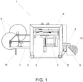
- Apparatus 1 shown in figure 1 comprises a frame 2 with wheels 3, 3' and a concrete saw 4 with a saw blade 5.
- the concrete saw 4 is connected to the frame 2 movably, so that the height and sideways orientation of the saw, or at least the saw blade 5, can be changed during sawing of the slipform cast concrete product.
- the orientation of the concrete saw 4 or saw blade 5 in relation to the vertical axis can also be changed, so that a slipform cast concrete product can be sawed to have a skewed or slanted edge, or so that a slipform cast concrete product or slab can be cut in half in length direction.
- the wheels 3, 3' of the apparatus 1 are set on rails extending on both sides of a slipform casting bed. These same rails are used by a slipform casting machine, as well as other finishing machines operating on the slipform cast concrete product.
- the wheels 3' are driven by a motor 6 in order to move the apparatus 1 along the casting bed.
- the platform 7 is equipped with two cable reels 8, one for electric cable for providing operating electric power for the apparatus 1, and one for water hose for providing water for the apparatus.
- the same water feed providing water to the apparatus 1 can be advantageously used both for the sawing process and for the cleaning and brushing process.
- a brushing unit 9 comprising a rotatable brush 10, which brush extends sideways from one end of the casting bed to another, thus covering and being able to clean the width of the casting bed.
- the brushing unit 9 is connected to the frame 2 of the apparatus 1 vertically adjustably, which allows the brushing unit to be used for brushing and cleaning the upper surface of a concrete product while the concrete product is still located on the casting bed. When the concrete product or products are removed from the casting bed, the brushing unit 9 is used for cleaning the casting bed.
- the brushing unit 9 is also equipped with a suction unit (not shown) for removing dust from the brushing and cleaning process of the casting bed as well as the upper surface of a concrete product.
- the apparatus 1 is equipped with a single suction unit for removing dust both from the sawing process and well as from the brushing and cleaning process.
- the apparatus 1 advantageously also comprises means (not shown) for spreading water on the casting bed during the brushing and cleaning process, which enhances the cleaning of the casting bed.
- a strand pulling comb 11 which extends substantially horizontally from one side of the casting bed to another, substantially perpendicularly in relation to the length direction of the casting bed.
- the strand pulling comb 11 is equipped with grooves extending upwards from the lower edge of the comb, and which grooves extend from the front surface of the comb to the back surface of the comb in the lengthwise direction of a casting bed. In these grooves of the strand pulling comb 11 are set ends of pretensioning strands to be pulled on the length of a casting bed.
- the strand pulling comb 11 is also connected to the apparatus 1 height adjustably so that it can be raised above the upper surface of a slipform cast concrete product during cutting processes.
- the apparatus 1 is also advantageously equipped with suitable means (not shown) for feeding oil to the casting bed and for spreading the oil on the casting bed.
- suitable means may include an oil container for providing the oil and a suitable wiper blade for spreading the oil on the casting bed.
- the apparatus 1 When the apparatus 1 is used, it is first lifted on a slipform casting bed and on a cured continuous slipform cast concrete product or slab so, that the wheels 3, 3' set on rails extending on both sides of the casting bed. Then the apparatus 1 is moved, by means of the motor 6, to a first cutting point where the continuous slipform cast product is to be cut, and the cutting is carried out with the concrete saw 4. After the sawing process is done, the apparatus proceeds forward so that the brushing unit 9 can be used to brush and clean any leftover cuttings and dust from the upper surface of the concrete product in the area of the cutting. Then the apparatus 1 starts to proceed to a next cutting point, and proceeds to cut the concrete product.
- the ready cut concrete product is lifted from the casting bed.
- the apparatus is moved to the end of the casting bed, where pretensioning strands are connected to the strand pulling comb.
- the apparatus 1 proceeds to cleaning of the casting bed with the brushing unit 9 and simultaneously moving and pulling the pretensioning strands to the other end of the casting bed.
- the pretensioning wires are detached from the apparatus, apparatus is lifted from the casting bed, and the casting bed is ready for tensioning of the pretensioning strands and for a new slipform casting process.
- the apparatus 1 may also be advantageously equipped with side or gutter brushing unit (not shown), which extends to the area next to the casting bed. This way the apparatus 1 can also clean simultaneously areas next to the casting bed or the gutters between casting beds.
- the weight of the concrete saw 4 provides advantageously enough weight for the whole apparatus, so that it is heavy enough for the cleaning process as well as for pulling the pretensioning strands.
- the weight of the machine needs to be raised by robust and heavy construction for these purposes, which raises the price of these prior art machines.
Landscapes
- Engineering & Computer Science (AREA)
- Mechanical Engineering (AREA)
- Mining & Mineral Resources (AREA)
- Chemical & Material Sciences (AREA)
- Ceramic Engineering (AREA)
- Structural Engineering (AREA)
- Manufacturing & Machinery (AREA)
- Processing Of Stones Or Stones Resemblance Materials (AREA)
- Cleaning In General (AREA)
- Sawing (AREA)
- Devices For Post-Treatments, Processing, Supply, Discharge, And Other Processes (AREA)
Description
- The present invention relates to an apparatus used for sawing cured slipform cast concrete products on a slipform casting bed before moving the cut concrete products from the casting bed, and in particular to an apparatus for sawing cured slipform cast concrete products according to the preamble of
claim 1. In slipform casting, concrete products are cast on a casting bed in one continuous casting process with slipform casting machine. After casting the one continuous concrete casting is left to cure on the casting bed. After the concrete is cured, the casting is cut to predetermined lengths defining the final concrete products, after which the final concrete products are lifted from the casting bed and transported either to storage or to their construction sites. - The removal of the cut concrete products or elements from the casting bed takes place immediately after the cutting, so that when the last cutting is done and the last element is lifted from the casting bed, the casting bed is ready for cleaning and refurnishing for a new slipform casting.
- The cutting of the cured concrete casting is generally done by a diamond bladed saw, which is supported by a frame comprising wheels, which allows the saw to be moved along and over the casting bed. The sawing process generally creates wet slurry, comprising of cooling water and concrete dust and cuttings, which slurry spreads on the casting bed as well as on the area next to or between the casting beds. This slurry needs to be cleaned before new slipform casting process on the casting bed may begin.
- The cleaning and refurnishing of the casting bed is generally done, especially in the larger concrete element manufacturing factories, with a separate machine, which usually cleans the casting bed with a rotating brush, oils the casting bed for protecting the metal parts of the casting bed, and draws pretensioning strands or wires from one end of the casting bed to another. The machine can be also equipped with side brush or brushes, which clean the area next to or between the casting beds. One this kind of machine is BedMaster manufactured by Elematic Oy Ab.
- After the casting bed is cleaned and the pretensioning strands are drawn on the length of the casting bed, the casting bed is ready for tensioning of the pretensioning strands and starting of the slipform casting process.
- The machines used in the cleaning and refurnishing are somewhat expensive and tie capital in machines, and thus are not used in many smaller concrete element manufacturing factories. These smaller concrete element manufacturers carry out the cleaning and refurnishing manually, which is hazardous to the employees' health due to the fine concrete and rock dust created in the sawing processes.
-
Publication EP 2 476 531 A1 from the same applicant discloses an apparatus according to the preamble ofclaim 1, in particular a concrete element saw comprising a frame with wheels and a concrete saw connected movably to the frame, wherein the torque of at least one feed motor of a saw blade and/or the torque of the drive motor moving the concrete element saw is measured, and the feed rate of the saw blade in adjusted on the basis of said measurement of the torque. - Publication
CN 201 202 077 Y discloses an expansion joint trimming machine for maintenance of cement concrete roads and airfield pavements of airports, which comprises a saw disc for removing dirt and calking from the expansion joint and a brush for collecting the removed debris to a container included in the machine. The brush can be raised from the surface to be cleaned. - The present invention provides an apparatus for sawing cured slipform cast concrete products defined by the features of
claim 1. The apparatus according to the present invention allows two consecutive manufacturing steps in the slipform cast concrete product manufacturing process to be carried out by the same machine thus lowering the capital tied to machinery of the manufacturing factory. This makes the apparatus appealing also to smaller manufacturing plants, which raises their level of automation and lower the health hazards to their personnel. As the apparatus comprises means for attaching ends of the pretensioning strands to the apparatus, said means comprising a strand pulling comb, the same machine can also be used to pull pretensioning strands on a slipform casting bed at the same time when the machine cleans the casting bed. Further, the additional weight of the concrete saw allows all of the required pretensioning strands to be pulled on the casting bed simultaneously, which is not usually possible with the cleaning machines of the prior art due to their low weight. This lowers the amount of passes to be made on the casting bed with machines, which also increases the work safety. - The apparatus according to the inventions is advantageously first used in the sawing process moving along the casting bed and sawing the cured slipform cast concrete product to a predetermined length, and after the concrete product is sawed to its predetermined length, the ready concrete product is lifted from the casting bed. After the last cut and removal of the last product from the casting bed the apparatus goes through the same casting bed, advantageously ends of pretensioning strands connected to the apparatus, and cleans the casting bed with the brushing unit. This single machine operation removes the need to change machines on the casting bed between the operations thus eliminating machined lifts on the manufacturing plant, which simplifies the manufacturing process and removes the hazards to the personnel caused by these machine lifts. The use of a single machine for these consecutive manufacturing steps also lowers the amount of machines to be operated simultaneously in the manufacturing plant, which significantly lessens the danger of personnel to get squeezed between two machines operating on adjacent casting beds.
- The apparatus according to the invention also allows the use of the brushing unit during the sawing process, whereby the brushing unit can be used to clean the upper surface of the slab from any leftover cuttings and dust.
- The apparatus according to an embodiment may advantageously also comprise a single suction unit for removing dust from both the concrete sawing process and the casting bed brushing process. This simplifies the construction of the apparatus.
- In the apparatus according to the invention the means for attaching the ends of the pretensioning strands to the apparatus are advantageously carried out with a strand pulling comb, which may extend at one end of the apparatus substantially horizontally.
- The apparatus according to a further embodiment may also be equipped with additional brushing unit for cleaning area next to and/or between adjacent slipform casting beds.
- The apparatus according to a further embodiment may also be equipped with means for oiling the slipform casting bed. This oiling helps to remove cured concrete from the surface of the casting bed and protects the metal parts of the casting bed.
- The apparatus according to a further embodiment may also be provided with a motor for moving the apparatus.
- Exemplifying embodiment of the invention and its advantages are explained in greater detail below in the sense of example and with reference to accompanying drawing, which
Figure 1 shows schematically as a side view an apparatus according to the invention. -
Apparatus 1 shown infigure 1 comprises aframe 2 withwheels 3, 3' and aconcrete saw 4 with asaw blade 5. Theconcrete saw 4 is connected to theframe 2 movably, so that the height and sideways orientation of the saw, or at least thesaw blade 5, can be changed during sawing of the slipform cast concrete product. The orientation of the concrete saw 4 orsaw blade 5 in relation to the vertical axis can also be changed, so that a slipform cast concrete product can be sawed to have a skewed or slanted edge, or so that a slipform cast concrete product or slab can be cut in half in length direction. - The
wheels 3, 3' of theapparatus 1 are set on rails extending on both sides of a slipform casting bed. These same rails are used by a slipform casting machine, as well as other finishing machines operating on the slipform cast concrete product. In the embodiment offigure 1 , the wheels 3' are driven by amotor 6 in order to move theapparatus 1 along the casting bed. - At one end of the
apparatus 1 is located an outwards extendingplatform 7, where an operator can operate the apparatus. Theplatform 7 is equipped with twocable reels 8, one for electric cable for providing operating electric power for theapparatus 1, and one for water hose for providing water for the apparatus. The same water feed providing water to theapparatus 1 can be advantageously used both for the sawing process and for the cleaning and brushing process. - In the opposite end of the
apparatus 1 in relation to theplatform 7 is connected abrushing unit 9 comprising arotatable brush 10, which brush extends sideways from one end of the casting bed to another, thus covering and being able to clean the width of the casting bed. Thebrushing unit 9 is connected to theframe 2 of theapparatus 1 vertically adjustably, which allows the brushing unit to be used for brushing and cleaning the upper surface of a concrete product while the concrete product is still located on the casting bed. When the concrete product or products are removed from the casting bed, thebrushing unit 9 is used for cleaning the casting bed. - The
brushing unit 9 is also equipped with a suction unit (not shown) for removing dust from the brushing and cleaning process of the casting bed as well as the upper surface of a concrete product. Advantageously theapparatus 1 is equipped with a single suction unit for removing dust both from the sawing process and well as from the brushing and cleaning process. Further, theapparatus 1 advantageously also comprises means (not shown) for spreading water on the casting bed during the brushing and cleaning process, which enhances the cleaning of the casting bed. - In the area of the
platform 7 is connected astrand pulling comb 11, which extends substantially horizontally from one side of the casting bed to another, substantially perpendicularly in relation to the length direction of the casting bed. Thestrand pulling comb 11 is equipped with grooves extending upwards from the lower edge of the comb, and which grooves extend from the front surface of the comb to the back surface of the comb in the lengthwise direction of a casting bed. In these grooves of thestrand pulling comb 11 are set ends of pretensioning strands to be pulled on the length of a casting bed. Thestrand pulling comb 11 is also connected to theapparatus 1 height adjustably so that it can be raised above the upper surface of a slipform cast concrete product during cutting processes. - The
apparatus 1 is also advantageously equipped with suitable means (not shown) for feeding oil to the casting bed and for spreading the oil on the casting bed. These means may include an oil container for providing the oil and a suitable wiper blade for spreading the oil on the casting bed. - When the
apparatus 1 is used, it is first lifted on a slipform casting bed and on a cured continuous slipform cast concrete product or slab so, that thewheels 3, 3' set on rails extending on both sides of the casting bed. Then theapparatus 1 is moved, by means of themotor 6, to a first cutting point where the continuous slipform cast product is to be cut, and the cutting is carried out with theconcrete saw 4. After the sawing process is done, the apparatus proceeds forward so that thebrushing unit 9 can be used to brush and clean any leftover cuttings and dust from the upper surface of the concrete product in the area of the cutting. Then theapparatus 1 starts to proceed to a next cutting point, and proceeds to cut the concrete product. Once theapparatus 1 has cleared and cleaned the area of the cut concrete product, the ready cut concrete product is lifted from the casting bed. After theapparatus 1 has proceeded from one end of the casting bed or from one end of the continuous slipform cast slab and carried out all the required sawing processes, the apparatus is moved to the end of the casting bed, where pretensioning strands are connected to the strand pulling comb. After the pretensioning wires are connected to thestrand comb 11, theapparatus 1 proceeds to cleaning of the casting bed with thebrushing unit 9 and simultaneously moving and pulling the pretensioning strands to the other end of the casting bed. When theapparatus 1 reaches the other end of the casting bed, the pretensioning wires are detached from the apparatus, apparatus is lifted from the casting bed, and the casting bed is ready for tensioning of the pretensioning strands and for a new slipform casting process. - The
apparatus 1 according to an embodiment may also be advantageously equipped with side or gutter brushing unit (not shown), which extends to the area next to the casting bed. This way theapparatus 1 can also clean simultaneously areas next to the casting bed or the gutters between casting beds. - In the
apparatus 1 according to the invention, the weight of the concrete saw 4 provides advantageously enough weight for the whole apparatus, so that it is heavy enough for the cleaning process as well as for pulling the pretensioning strands. In the prior art cleaning machines the weight of the machine needs to be raised by robust and heavy construction for these purposes, which raises the price of these prior art machines. - Regarding the embodiment illustrated in the figure and discussed above, it should be appreciated that it is just an example of a solution according to the invention and, hence, by no means limiting the invention. It is evident to a person skilled in the art that the disclosed embodiment can be modified in many different ways within the scope of the appended claims.
Claims (5)
- An apparatus (1) for sawing cured slipform cast concrete products, which apparatus comprises a frame (2) with wheels (3, 3') for moving the apparatus along a casting bed, and a concrete saw (4) connected movably to the frame, characterized in that the apparatus (1) comprises a brushing unit (9) for cleaning slipform casting bed, wherein the brushing unit (9) is connected to the frame (2) of the apparatus vertically adjustably for allowing the brushing unit to be used in cleaning the upper surface of a cast concrete product on a slipform casting bed, and in that the apparatus further comprises means (11) for attaching ends of pretensioning strands to the apparatus, said means comprising a strand pulling comb.
- An apparatus (1) according to claim 1, wherein the apparatus comprises a suction unit for removing dust from both the concrete sawing process and the casting bed brushing process.
- An apparatus (1) according to any of claims 1 or 2, wherein the apparatus comprises a brushing unit for cleaning area next to and/or between adjacent slipform casting beds.
- An apparatus (1) according to any of claims 1-3, wherein the apparatus comprises means for oiling the slipform casting bed.
- An apparatus (1) according to any of claims 1-4, wherein the apparatus comprises a motor (6) for moving the apparatus.
Applications Claiming Priority (1)
| Application Number | Priority Date | Filing Date | Title |
|---|---|---|---|
| FI20126318A FI124184B (en) | 2012-12-17 | 2012-12-17 | Apparatus for cutting sliding cast concrete products |
Publications (2)
| Publication Number | Publication Date |
|---|---|
| EP2743050A1 EP2743050A1 (en) | 2014-06-18 |
| EP2743050B1 true EP2743050B1 (en) | 2018-07-04 |
Family
ID=49911380
Family Applications (1)
| Application Number | Title | Priority Date | Filing Date |
|---|---|---|---|
| EP13397546.6A Active EP2743050B1 (en) | 2012-12-17 | 2013-12-16 | Apparatus for sawing cured slipform cast concrete products |
Country Status (6)
| Country | Link |
|---|---|
| US (1) | US9221193B2 (en) |
| EP (1) | EP2743050B1 (en) |
| CN (1) | CN103862559B (en) |
| ES (1) | ES2689807T3 (en) |
| FI (1) | FI124184B (en) |
| RU (1) | RU2636193C2 (en) |
Families Citing this family (3)
| Publication number | Priority date | Publication date | Assignee | Title |
|---|---|---|---|---|
| CN106625104B (en) * | 2017-03-22 | 2018-11-30 | 天津盛世舜合自动化技术有限公司 | A kind of closestool bottom processing unit (plant) |
| CN111441252B (en) * | 2020-04-07 | 2021-11-16 | 烟台大学 | Vertical cutting equipment is used in road and bridge construction |
| CN112845227A (en) * | 2021-03-05 | 2021-05-28 | 广东博智林机器人有限公司 | Cleaning and oiling robot |
Citations (5)
| Publication number | Priority date | Publication date | Assignee | Title |
|---|---|---|---|---|
| GB551996A (en) * | 1941-09-19 | 1943-03-18 | Maurice John Gleeson | A groove-cutting machine for use in making expansion joints in roadways and the like |
| US5035592A (en) * | 1987-12-11 | 1991-07-30 | Lowndes Corporation | Apparatus for concrete supply and form vibration |
| US20030213482A1 (en) * | 2002-05-15 | 2003-11-20 | John P. Buser | Debris-collection device for a power saw |
| JP2007255061A (en) * | 2006-03-23 | 2007-10-04 | Daiichi Cutter Kogyo Kk | Hole wall roughening device and hole wall roughening method |
| CN201202077Y (en) * | 2008-04-09 | 2009-03-04 | 聂伟 | Expansion joint finisher for cement concrete road and aerodrome runway surface |
Family Cites Families (30)
| Publication number | Priority date | Publication date | Assignee | Title |
|---|---|---|---|---|
| CH400887A (en) | 1962-11-14 | 1965-10-15 | Roehr Alfred | Device for the production of shaped stones from concrete |
| US3378307A (en) * | 1965-07-22 | 1968-04-16 | Concrete Cutting Equipment Co | Circular saw for cutting concrete surfaces |
| US3417638A (en) * | 1967-07-24 | 1968-12-24 | Robert G Evans Company | Road speed drive mechanism for self-propelled concrete saws and the like |
| US3464737A (en) * | 1967-09-11 | 1969-09-02 | Robert G Evans Co | Road grooving apparatus |
| US3901553A (en) * | 1974-10-30 | 1975-08-26 | Materials Inc Const | Concrete pavement cutting machine |
| SU733994A1 (en) * | 1977-12-23 | 1980-05-20 | Пензенский Инженерно-Строительный Институт | Device for cutting cellular concrete |
| DE2800217A1 (en) | 1978-01-04 | 1979-07-12 | Jochen Hillje | Washing machine for concrete slabs - has brushes mounted on oscillating beam driven by pair of crankshafts |
| JPS58970B2 (en) * | 1980-06-03 | 1983-01-08 | 大給 慎吾 | Circular saw blade soundproofing device |
| US5429420A (en) * | 1994-01-03 | 1995-07-04 | Norton Company | Pavement cutting saw |
| US5724956A (en) * | 1996-03-06 | 1998-03-10 | Diamond Products Joint Venture | Riding saw for cutting concrete and similar materials |
| GB2311747A (en) | 1996-04-04 | 1997-10-08 | Nordimpianti Otm Srl | Process and plant for the production of pre-stressed concrete products |
| US6019433A (en) * | 1997-10-24 | 2000-02-01 | Allen Engineering Corporation | Concrete saw with stabilized carriage and blade control |
| US6131557A (en) * | 1999-04-22 | 2000-10-17 | Mixer Systems, Inc. | Two stage variable speed control for concrete saw |
| CN2535212Y (en) * | 2002-04-02 | 2003-02-12 | 曹利华 | Wall cutting machine |
| US20030196650A1 (en) * | 2002-04-23 | 2003-10-23 | Andrew Bowman | Telescoping guide for a concrete saw |
| CN2704461Y (en) * | 2003-12-28 | 2005-06-15 | 魏文烃 | Concrete structural section paving cutters |
| US20060191526A1 (en) * | 2004-08-31 | 2006-08-31 | Markley Charles E | Skid plate for concrete saw |
| US7451757B2 (en) * | 2006-03-07 | 2008-11-18 | Ketterhagen Frederick A | Concrete cutter |
| US8061344B2 (en) * | 2006-09-11 | 2011-11-22 | Teraspan Networks Inc. | Slab saw with dust collector and method of dry-cutting pavement |
| US20090236900A1 (en) * | 2008-01-19 | 2009-09-24 | Joseph Eugene Due | Dust and debris evacuator for cut-off saw |
| US8118018B1 (en) * | 2008-03-14 | 2012-02-21 | The John T. Sherment Trust | Horizontal concrete saw attachment |
| US8360045B2 (en) * | 2008-07-28 | 2013-01-29 | Diamond Products, Limited | Concrete saw |
| US8733845B2 (en) * | 2009-08-12 | 2014-05-27 | Kevin Bollinger | Systems, machines, devices and methods for efficiently removing sidewalk trip hazards |
| US20110278907A1 (en) * | 2010-05-12 | 2011-11-17 | Diamond Products, Limited | Concrete Profiler With Vacuum System |
| JP5525963B2 (en) * | 2010-08-20 | 2014-06-18 | 株式会社マキタ | Electric tool with dust collector |
| US20120174905A1 (en) | 2011-01-11 | 2012-07-12 | Wy Peron Lee | Ground level portable saw machine |
| FI20115048A7 (en) * | 2011-01-18 | 2012-07-19 | Elematic Oyj | Method for adjusting the cutting speed of a precast concrete saw and a precast concrete saw |
| CN102155093A (en) * | 2011-03-10 | 2011-08-17 | 绍兴文理学院 | Concrete cast-in-place surface napping machine |
| CN102241059B (en) * | 2011-06-30 | 2013-03-27 | 常州力顿机械科技有限公司 | Aerated concrete cutting machine |
| US9027542B2 (en) * | 2013-02-14 | 2015-05-12 | Perfect Trac Opco, Llc | Powered saw including dust capture apparatus |
-
2012
- 2012-12-17 FI FI20126318A patent/FI124184B/en active IP Right Grant
-
2013
- 2013-12-12 RU RU2013155030A patent/RU2636193C2/en active
- 2013-12-16 EP EP13397546.6A patent/EP2743050B1/en active Active
- 2013-12-16 ES ES13397546.6T patent/ES2689807T3/en active Active
- 2013-12-17 US US14/108,989 patent/US9221193B2/en active Active
- 2013-12-17 CN CN201310692411.7A patent/CN103862559B/en active Active
Patent Citations (5)
| Publication number | Priority date | Publication date | Assignee | Title |
|---|---|---|---|---|
| GB551996A (en) * | 1941-09-19 | 1943-03-18 | Maurice John Gleeson | A groove-cutting machine for use in making expansion joints in roadways and the like |
| US5035592A (en) * | 1987-12-11 | 1991-07-30 | Lowndes Corporation | Apparatus for concrete supply and form vibration |
| US20030213482A1 (en) * | 2002-05-15 | 2003-11-20 | John P. Buser | Debris-collection device for a power saw |
| JP2007255061A (en) * | 2006-03-23 | 2007-10-04 | Daiichi Cutter Kogyo Kk | Hole wall roughening device and hole wall roughening method |
| CN201202077Y (en) * | 2008-04-09 | 2009-03-04 | 聂伟 | Expansion joint finisher for cement concrete road and aerodrome runway surface |
Also Published As
| Publication number | Publication date |
|---|---|
| FI20126318A7 (en) | 2014-04-15 |
| ES2689807T3 (en) | 2018-11-15 |
| RU2636193C2 (en) | 2017-11-21 |
| RU2013155030A (en) | 2015-06-20 |
| EP2743050A1 (en) | 2014-06-18 |
| FI124184B (en) | 2014-04-15 |
| US20140165986A1 (en) | 2014-06-19 |
| CN103862559A (en) | 2014-06-18 |
| CN103862559B (en) | 2017-11-10 |
| US9221193B2 (en) | 2015-12-29 |
Similar Documents
| Publication | Publication Date | Title |
|---|---|---|
| KR101262235B1 (en) | Cut working apparatus and method of non-slip road boundary stone using natural stone | |
| US9221193B2 (en) | Apparatus for sawing cured slipform cast concrete products | |
| US20070209651A1 (en) | Concrete cutter | |
| DE102005000013A1 (en) | Controllable wall saw and control method | |
| CN107553752A (en) | A kind of stone cutting method of temperature lowering water reusable edible | |
| CN107498718A (en) | A kind of stone cutting device of temperature lowering water reusable edible | |
| DE202018001352U1 (en) | Device for removing grout during joint renovation | |
| CN112982119A (en) | Joint cutting device for road and bridge construction | |
| CN220698992U (en) | Steel cutting device for construction | |
| CN209903606U (en) | Cutting device for light stone slabs | |
| US11725352B2 (en) | Hydro demolition unit | |
| US11992971B2 (en) | Sawcut machine for sidewalks | |
| EP0849059B1 (en) | Twin blade V-groove cutter | |
| CN207310284U (en) | A kind of full-automatic bilateral bead cutter | |
| CN218855489U (en) | Steel bar cutting device for high-strength concrete protection equipment | |
| CN106312183A (en) | Product surface treatment device | |
| CN214720968U (en) | Cutting device is used in steel guardrail production | |
| EP0836920A1 (en) | Mobile portal-frame machine for cutting blocks of granite, marble and stone in general, and relative plant | |
| CN217255141U (en) | Cleaning device is used in ball tooth production | |
| CN105798728A (en) | Edge grinding device for machining columnar stone pier | |
| CN115592821B (en) | A marble slab production line | |
| CN220348756U (en) | Self-heat-preservation building block drawknot tendon groove chiseling equipment | |
| US2815745A (en) | Gang saw construction for cutting stone | |
| CN220013324U (en) | Pavement cutting machine | |
| KR101147037B1 (en) | Noise reduction type sandwich panel cutting apparatus |
Legal Events
| Date | Code | Title | Description |
|---|---|---|---|
| PUAI | Public reference made under article 153(3) epc to a published international application that has entered the european phase |
Free format text: ORIGINAL CODE: 0009012 |
|
| 17P | Request for examination filed |
Effective date: 20131216 |
|
| AK | Designated contracting states |
Kind code of ref document: A1 Designated state(s): AL AT BE BG CH CY CZ DE DK EE ES FI FR GB GR HR HU IE IS IT LI LT LU LV MC MK MT NL NO PL PT RO RS SE SI SK SM TR |
|
| AX | Request for extension of the european patent |
Extension state: BA ME |
|
| R17P | Request for examination filed (corrected) |
Effective date: 20141107 |
|
| RBV | Designated contracting states (corrected) |
Designated state(s): AL AT BE BG CH CY CZ DE DK EE ES FI FR GB GR HR HU IE IS IT LI LT LU LV MC MK MT NL NO PL PT RO RS SE SI SK SM TR |
|
| RAP1 | Party data changed (applicant data changed or rights of an application transferred) |
Owner name: ELEMATIC OYJ |
|
| 17Q | First examination report despatched |
Effective date: 20160819 |
|
| GRAP | Despatch of communication of intention to grant a patent |
Free format text: ORIGINAL CODE: EPIDOSNIGR1 |
|
| INTG | Intention to grant announced |
Effective date: 20180321 |
|
| GRAS | Grant fee paid |
Free format text: ORIGINAL CODE: EPIDOSNIGR3 |
|
| GRAA | (expected) grant |
Free format text: ORIGINAL CODE: 0009210 |
|
| AK | Designated contracting states |
Kind code of ref document: B1 Designated state(s): AL AT BE BG CH CY CZ DE DK EE ES FI FR GB GR HR HU IE IS IT LI LT LU LV MC MK MT NL NO PL PT RO RS SE SI SK SM TR |
|
| REG | Reference to a national code |
Ref country code: GB Ref legal event code: FG4D |
|
| REG | Reference to a national code |
Ref country code: CH Ref legal event code: EP |
|
| REG | Reference to a national code |
Ref country code: AT Ref legal event code: REF Ref document number: 1014012 Country of ref document: AT Kind code of ref document: T Effective date: 20180715 |
|
| REG | Reference to a national code |
Ref country code: IE Ref legal event code: FG4D |
|
| REG | Reference to a national code |
Ref country code: DE Ref legal event code: R096 Ref document number: 602013039658 Country of ref document: DE |
|
| REG | Reference to a national code |
Ref country code: NL Ref legal event code: FP |
|
| REG | Reference to a national code |
Ref country code: ES Ref legal event code: FG2A Ref document number: 2689807 Country of ref document: ES Kind code of ref document: T3 Effective date: 20181115 |
|
| REG | Reference to a national code |
Ref country code: LT Ref legal event code: MG4D |
|
| REG | Reference to a national code |
Ref country code: AT Ref legal event code: MK05 Ref document number: 1014012 Country of ref document: AT Kind code of ref document: T Effective date: 20180704 |
|
| PG25 | Lapsed in a contracting state [announced via postgrant information from national office to epo] |
Ref country code: NO Free format text: LAPSE BECAUSE OF FAILURE TO SUBMIT A TRANSLATION OF THE DESCRIPTION OR TO PAY THE FEE WITHIN THE PRESCRIBED TIME-LIMIT Effective date: 20181004 Ref country code: GR Free format text: LAPSE BECAUSE OF FAILURE TO SUBMIT A TRANSLATION OF THE DESCRIPTION OR TO PAY THE FEE WITHIN THE PRESCRIBED TIME-LIMIT Effective date: 20181005 Ref country code: BG Free format text: LAPSE BECAUSE OF FAILURE TO SUBMIT A TRANSLATION OF THE DESCRIPTION OR TO PAY THE FEE WITHIN THE PRESCRIBED TIME-LIMIT Effective date: 20181004 Ref country code: CZ Free format text: LAPSE BECAUSE OF FAILURE TO SUBMIT A TRANSLATION OF THE DESCRIPTION OR TO PAY THE FEE WITHIN THE PRESCRIBED TIME-LIMIT Effective date: 20180704 Ref country code: AT Free format text: LAPSE BECAUSE OF FAILURE TO SUBMIT A TRANSLATION OF THE DESCRIPTION OR TO PAY THE FEE WITHIN THE PRESCRIBED TIME-LIMIT Effective date: 20180704 Ref country code: PL Free format text: LAPSE BECAUSE OF FAILURE TO SUBMIT A TRANSLATION OF THE DESCRIPTION OR TO PAY THE FEE WITHIN THE PRESCRIBED TIME-LIMIT Effective date: 20180704 Ref country code: IS Free format text: LAPSE BECAUSE OF FAILURE TO SUBMIT A TRANSLATION OF THE DESCRIPTION OR TO PAY THE FEE WITHIN THE PRESCRIBED TIME-LIMIT Effective date: 20181104 Ref country code: RS Free format text: LAPSE BECAUSE OF FAILURE TO SUBMIT A TRANSLATION OF THE DESCRIPTION OR TO PAY THE FEE WITHIN THE PRESCRIBED TIME-LIMIT Effective date: 20180704 Ref country code: FI Free format text: LAPSE BECAUSE OF FAILURE TO SUBMIT A TRANSLATION OF THE DESCRIPTION OR TO PAY THE FEE WITHIN THE PRESCRIBED TIME-LIMIT Effective date: 20180704 Ref country code: LT Free format text: LAPSE BECAUSE OF FAILURE TO SUBMIT A TRANSLATION OF THE DESCRIPTION OR TO PAY THE FEE WITHIN THE PRESCRIBED TIME-LIMIT Effective date: 20180704 Ref country code: SE Free format text: LAPSE BECAUSE OF FAILURE TO SUBMIT A TRANSLATION OF THE DESCRIPTION OR TO PAY THE FEE WITHIN THE PRESCRIBED TIME-LIMIT Effective date: 20180704 |
|
| PG25 | Lapsed in a contracting state [announced via postgrant information from national office to epo] |
Ref country code: AL Free format text: LAPSE BECAUSE OF FAILURE TO SUBMIT A TRANSLATION OF THE DESCRIPTION OR TO PAY THE FEE WITHIN THE PRESCRIBED TIME-LIMIT Effective date: 20180704 Ref country code: LV Free format text: LAPSE BECAUSE OF FAILURE TO SUBMIT A TRANSLATION OF THE DESCRIPTION OR TO PAY THE FEE WITHIN THE PRESCRIBED TIME-LIMIT Effective date: 20180704 Ref country code: HR Free format text: LAPSE BECAUSE OF FAILURE TO SUBMIT A TRANSLATION OF THE DESCRIPTION OR TO PAY THE FEE WITHIN THE PRESCRIBED TIME-LIMIT Effective date: 20180704 |
|
| REG | Reference to a national code |
Ref country code: DE Ref legal event code: R097 Ref document number: 602013039658 Country of ref document: DE |
|
| PG25 | Lapsed in a contracting state [announced via postgrant information from national office to epo] |
Ref country code: EE Free format text: LAPSE BECAUSE OF FAILURE TO SUBMIT A TRANSLATION OF THE DESCRIPTION OR TO PAY THE FEE WITHIN THE PRESCRIBED TIME-LIMIT Effective date: 20180704 Ref country code: RO Free format text: LAPSE BECAUSE OF FAILURE TO SUBMIT A TRANSLATION OF THE DESCRIPTION OR TO PAY THE FEE WITHIN THE PRESCRIBED TIME-LIMIT Effective date: 20180704 |
|
| PLBE | No opposition filed within time limit |
Free format text: ORIGINAL CODE: 0009261 |
|
| STAA | Information on the status of an ep patent application or granted ep patent |
Free format text: STATUS: NO OPPOSITION FILED WITHIN TIME LIMIT |
|
| PG25 | Lapsed in a contracting state [announced via postgrant information from national office to epo] |
Ref country code: SM Free format text: LAPSE BECAUSE OF FAILURE TO SUBMIT A TRANSLATION OF THE DESCRIPTION OR TO PAY THE FEE WITHIN THE PRESCRIBED TIME-LIMIT Effective date: 20180704 Ref country code: DK Free format text: LAPSE BECAUSE OF FAILURE TO SUBMIT A TRANSLATION OF THE DESCRIPTION OR TO PAY THE FEE WITHIN THE PRESCRIBED TIME-LIMIT Effective date: 20180704 Ref country code: SK Free format text: LAPSE BECAUSE OF FAILURE TO SUBMIT A TRANSLATION OF THE DESCRIPTION OR TO PAY THE FEE WITHIN THE PRESCRIBED TIME-LIMIT Effective date: 20180704 |
|
| 26N | No opposition filed |
Effective date: 20190405 |
|
| REG | Reference to a national code |
Ref country code: CH Ref legal event code: PL |
|
| PG25 | Lapsed in a contracting state [announced via postgrant information from national office to epo] |
Ref country code: MC Free format text: LAPSE BECAUSE OF FAILURE TO SUBMIT A TRANSLATION OF THE DESCRIPTION OR TO PAY THE FEE WITHIN THE PRESCRIBED TIME-LIMIT Effective date: 20180704 Ref country code: SI Free format text: LAPSE BECAUSE OF FAILURE TO SUBMIT A TRANSLATION OF THE DESCRIPTION OR TO PAY THE FEE WITHIN THE PRESCRIBED TIME-LIMIT Effective date: 20180704 Ref country code: LU Free format text: LAPSE BECAUSE OF NON-PAYMENT OF DUE FEES Effective date: 20181216 |
|
| REG | Reference to a national code |
Ref country code: IE Ref legal event code: MM4A |
|
| PG25 | Lapsed in a contracting state [announced via postgrant information from national office to epo] |
Ref country code: IE Free format text: LAPSE BECAUSE OF NON-PAYMENT OF DUE FEES Effective date: 20181216 |
|
| PG25 | Lapsed in a contracting state [announced via postgrant information from national office to epo] |
Ref country code: LI Free format text: LAPSE BECAUSE OF NON-PAYMENT OF DUE FEES Effective date: 20181231 Ref country code: CH Free format text: LAPSE BECAUSE OF NON-PAYMENT OF DUE FEES Effective date: 20181231 |
|
| PG25 | Lapsed in a contracting state [announced via postgrant information from national office to epo] |
Ref country code: MT Free format text: LAPSE BECAUSE OF NON-PAYMENT OF DUE FEES Effective date: 20181216 |
|
| PG25 | Lapsed in a contracting state [announced via postgrant information from national office to epo] |
Ref country code: TR Free format text: LAPSE BECAUSE OF FAILURE TO SUBMIT A TRANSLATION OF THE DESCRIPTION OR TO PAY THE FEE WITHIN THE PRESCRIBED TIME-LIMIT Effective date: 20180704 |
|
| PG25 | Lapsed in a contracting state [announced via postgrant information from national office to epo] |
Ref country code: PT Free format text: LAPSE BECAUSE OF FAILURE TO SUBMIT A TRANSLATION OF THE DESCRIPTION OR TO PAY THE FEE WITHIN THE PRESCRIBED TIME-LIMIT Effective date: 20180704 |
|
| PG25 | Lapsed in a contracting state [announced via postgrant information from national office to epo] |
Ref country code: CY Free format text: LAPSE BECAUSE OF FAILURE TO SUBMIT A TRANSLATION OF THE DESCRIPTION OR TO PAY THE FEE WITHIN THE PRESCRIBED TIME-LIMIT Effective date: 20180704 Ref country code: HU Free format text: LAPSE BECAUSE OF FAILURE TO SUBMIT A TRANSLATION OF THE DESCRIPTION OR TO PAY THE FEE WITHIN THE PRESCRIBED TIME-LIMIT; INVALID AB INITIO Effective date: 20131216 Ref country code: MK Free format text: LAPSE BECAUSE OF NON-PAYMENT OF DUE FEES Effective date: 20180704 |
|
| PGFP | Annual fee paid to national office [announced via postgrant information from national office to epo] |
Ref country code: DE Payment date: 20251211 Year of fee payment: 13 |
|
| PGFP | Annual fee paid to national office [announced via postgrant information from national office to epo] |
Ref country code: GB Payment date: 20251219 Year of fee payment: 13 |
|
| PGFP | Annual fee paid to national office [announced via postgrant information from national office to epo] |
Ref country code: IT Payment date: 20251219 Year of fee payment: 13 |
|
| PGFP | Annual fee paid to national office [announced via postgrant information from national office to epo] |
Ref country code: NL Payment date: 20251219 Year of fee payment: 13 Ref country code: FR Payment date: 20251223 Year of fee payment: 13 |
|
| PGFP | Annual fee paid to national office [announced via postgrant information from national office to epo] |
Ref country code: BE Payment date: 20251219 Year of fee payment: 13 |
|
| PGFP | Annual fee paid to national office [announced via postgrant information from national office to epo] |
Ref country code: ES Payment date: 20260130 Year of fee payment: 13 |