EP2743045B1 - Dust extraction system and web slitters equipped therewith - Google Patents
Dust extraction system and web slitters equipped therewith Download PDFInfo
- Publication number
- EP2743045B1 EP2743045B1 EP20120197431 EP12197431A EP2743045B1 EP 2743045 B1 EP2743045 B1 EP 2743045B1 EP 20120197431 EP20120197431 EP 20120197431 EP 12197431 A EP12197431 A EP 12197431A EP 2743045 B1 EP2743045 B1 EP 2743045B1
- Authority
- EP
- European Patent Office
- Prior art keywords
- manifold
- fins
- extraction
- head
- dust
- Prior art date
- Legal status (The legal status is an assumption and is not a legal conclusion. Google has not performed a legal analysis and makes no representation as to the accuracy of the status listed.)
- Not-in-force
Links
- 238000000605 extraction Methods 0.000 title claims description 72
- 239000000428 dust Substances 0.000 title claims description 51
- 238000007789 sealing Methods 0.000 claims description 17
- 239000012080 ambient air Substances 0.000 claims description 3
- 239000003570 air Substances 0.000 description 18
- 210000003414 extremity Anatomy 0.000 description 8
- 239000000203 mixture Substances 0.000 description 3
- 230000009471 action Effects 0.000 description 2
- 238000001125 extrusion Methods 0.000 description 2
- 238000003780 insertion Methods 0.000 description 2
- 230000037431 insertion Effects 0.000 description 2
- 229910001234 light alloy Inorganic materials 0.000 description 2
- 239000000463 material Substances 0.000 description 1
- 230000007246 mechanism Effects 0.000 description 1
- 238000000034 method Methods 0.000 description 1
- 230000004048 modification Effects 0.000 description 1
- 238000012986 modification Methods 0.000 description 1
- 230000008569 process Effects 0.000 description 1
- 230000000135 prohibitive effect Effects 0.000 description 1
- 230000009467 reduction Effects 0.000 description 1
- 238000004904 shortening Methods 0.000 description 1
- 210000001364 upper extremity Anatomy 0.000 description 1
Images



Classifications
-
- B—PERFORMING OPERATIONS; TRANSPORTING
- B26—HAND CUTTING TOOLS; CUTTING; SEVERING
- B26D—CUTTING; DETAILS COMMON TO MACHINES FOR PERFORATING, PUNCHING, CUTTING-OUT, STAMPING-OUT OR SEVERING
- B26D7/00—Details of apparatus for cutting, cutting-out, stamping-out, punching, perforating, or severing by means other than cutting
- B26D7/18—Means for removing cut-out material or waste
- B26D7/1845—Means for removing cut-out material or waste by non mechanical means
- B26D7/1863—Means for removing cut-out material or waste by non mechanical means by suction
-
- B—PERFORMING OPERATIONS; TRANSPORTING
- B26—HAND CUTTING TOOLS; CUTTING; SEVERING
- B26D—CUTTING; DETAILS COMMON TO MACHINES FOR PERFORATING, PUNCHING, CUTTING-OUT, STAMPING-OUT OR SEVERING
- B26D1/00—Cutting through work characterised by the nature or movement of the cutting member or particular materials not otherwise provided for; Apparatus or machines therefor; Cutting members therefor
- B26D1/01—Cutting through work characterised by the nature or movement of the cutting member or particular materials not otherwise provided for; Apparatus or machines therefor; Cutting members therefor involving a cutting member which does not travel with the work
- B26D1/12—Cutting through work characterised by the nature or movement of the cutting member or particular materials not otherwise provided for; Apparatus or machines therefor; Cutting members therefor involving a cutting member which does not travel with the work having a cutting member moving about an axis
- B26D1/14—Cutting through work characterised by the nature or movement of the cutting member or particular materials not otherwise provided for; Apparatus or machines therefor; Cutting members therefor involving a cutting member which does not travel with the work having a cutting member moving about an axis with a circular cutting member, e.g. disc cutter
- B26D1/24—Cutting through work characterised by the nature or movement of the cutting member or particular materials not otherwise provided for; Apparatus or machines therefor; Cutting members therefor involving a cutting member which does not travel with the work having a cutting member moving about an axis with a circular cutting member, e.g. disc cutter coacting with another disc cutter
- B26D1/245—Cutting through work characterised by the nature or movement of the cutting member or particular materials not otherwise provided for; Apparatus or machines therefor; Cutting members therefor involving a cutting member which does not travel with the work having a cutting member moving about an axis with a circular cutting member, e.g. disc cutter coacting with another disc cutter for thin material, e.g. for sheets, strips or the like
Definitions
- the invention relates to dust extraction systems and web slitters equipped therewith.
- the traditional dust extraction systems as used on the Applicant's slitter/rewinding machines include dust extraction hoses attached at one end to the male knife and at the other end to a fixed dust extraction manifold.
- a vacuum pump is provided to suck the dust away from the blade along the dust extraction hoses into the dust extraction manifold from where it is delivered to the dust collection vessel.
- the male knife may be positioned anywhere along the male knife beam within the limits imposed by the length of the dust extraction hose.
- Current dust extraction systems restrict the lateral movement of a knife blade during automatic knife positioning and manual knife positioning.
- the extraction hose of the prior art is secured in close proximity to the blade of the male knife and to the extraction manifold by respective hose clamps. These hose clamps are usually of the Chenny or Jubilee type.
- the extraction manifold is normally secured to the male knife beam.
- the hose used to link the knife holder to the manifold restricts the movement of the knife thereby limiting the set-ups that can be achieved with standard hoses.
- Extended hoses can be used to overcome this restriction but the cost and complexity of handling the additional hose length safely is prohibitive.
- US-5,031, 494 discloses a device which defines the preamble of claim 1.
- the invention is defined in claim 1. This configuration is particularly advantageous because it avoids the traditional requirement of one hole in the manifold for a particular hose end. Instead of discrete positioning of the end of an extractor conduit, unlimited male knife positioning may be achieved in the elongate channel. The requirements for potentially fiddly and complex clips are avoided. The male knives may be added or removed quickly and simply without the need for extensive technical assistance or spare parts other than the extra male knife.
- the seal is formed from two oppositely positioned sealing strips; whereby, in use, the relatively low pressure in the extraction manifold combines with the relatively high ambient air pressure to push said portions against said head.
- This configuration is particularly advantageous since it allows the strips to be relatively straightforwardly parted for the removal of the head whilst at the same time allowing a tight fit on the extraction head.
- the knife blade allows the knife blade to be positioned in any appropriate position of the elongate channel. Consequently, downtime if any, for the replacement of a knife blade is kept to the minimum with little or no requirement for modification of the manifold.
- the sealing strip portions are bowed. This increases the surface area of contact between the inner portion of the sealing strips and the head of the extraction system.
- the head incorporates an upper aperture and laterally extending fins. This configuration is particularly advantageous in terms of allowing the parting of the sealing strips for the insertion or the removal of the head.
- the fins are tapered. This further improves the ability of the fins to be used in parting the sealing strips.
- the fins are tapered in varying width from an upper portion of the fins to a lower portion of the fins. This further improves the ability of the fins being used to part the sealing strips.
- the fins decrease in thickness in the lateral direction. This provides a relatively pointed lateral extremity for the fins further facilitating the parting of the sealing strips.
- the fins are rounded. This configuration is particularly advantageous in terms of removing the sharp edges which may otherwise damage the air tightness of the extraction manifold.
- the extractor conduit incorporates a rigid telescopic portion.
- This configuration is particularly advantageous as it limits the degree of motion other than in the telescopic direction.
- the internal surfaces of the rigid telescopic portion are relatively smooth which reduces the level of turbulence and consequently noise during the suction process.
- both the extraction manifold and the fan are mounted onto the male knife blade beam. This further improves the suction properties of the dust extraction system.
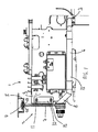
- FIG. 1 shows a knife blade assembly 1 equipped with a dust extraction system generally referenced 2.
- the dust extraction system incorporates an extractor conduit which at its proximal extremity 3 is in an area adjacent the slitting operation and which at its distal extremity incorporates a head 4 which engages with extraction manifold 5.
- the extractor conduit 2 incorporates a telescoping extraction tube 6 and a manifold seal deflector 7.
- the telescoping extraction tube 6 extends laterally whilst the manifold seal deflector 7 extends upwardly.
- the telescoping extraction tube 6 and the deflector 7 are joined together by a tube section 8 provided at an angle.
- the deflector is secured onto the mounting plate 9 by the mounting plate 10.
- Releasable attachment means such as fasteners 11 and 12 immobilise the deflector relative to the plate 9.
- the telescoping extraction tube 6 incorporates a number of concentric tubular portions which slide relative to one another in order to achieve a lengthening or a shortening of the tube.
- the central portion 13 of the telescoping extraction tube provides a relatively smooth internal surface.
- the manifold seal deflector 7 provides a substantially oblong internal cavity through which a mixture of air and dust travel upwards.
- the upper extremity of the deflector incorporates a head 4 which has at least one but preferably two laterally extending fins 14 and 15. These fins are wedge shaped and reduce in thickness towards their distal extremities 16 and 17.
- Alternative head configurations are presented in Figure 8 where distal extremities 18 and 19 are rounded, distal extremities 20 and 21 progressively increase in width and, extremities 22 and 23 where a reduction in width is provided from an upper portion to a lower portion.
- the head of the manifold seal deflector has tapered ends machined perpendicular to maximise the sealing efficiency when traversing the manifold seals 24 and 25.
- the seal is formed of two sealing strips 24 and 25 which are upwardly bowed and abut each other at their distal extremities.
- the sealing strips will be of inherently flexible material in order to accommodate the insertion of the fins of the head.
- the sealing strips fit tightly in an elongate channel generally referenced 26.
- the dust extraction manifold 5 may be mounted onto the male knife beam 27 through releasable attachment means 28 and 29.
- the extraction manifold may be substantially U-shaped.
- An aperture 30 may be provided between the extraction manifold and the male knife beam 27. Extractor fans may be provided on at least one side of the male knife beam as shown for example in Figure 5 where pumps 31 and 32 can draw air from the internal cavity of the male knife beam 27.
- the tapered ends of the head part the seal gradually, preventing loss of air from the dust extraction manifold. Sealing is increased by flowing air (low pressure) in the dust extraction manifold exerting an upward "pull" on the seals forcing them against the head of the extraction system whilst the ambient air (high pressure) push the seal onto the head.
- the length of the taper offers least resistance and best sealing efficiency.
- the dust extraction manifold 5 may be formed of two parts 33 and 34. These parts may be light alloy extrusions. Each light alloy extrusion may have the facility to accommodate sealing strips as shown in the previous figures. The ends of the dust extraction manifold may be closed by a closure plate or other appropriate closure means. As shown in Figure 3 , the dust extraction manifold 5 is mounted directly onto the male knife beam 27. The holes machined through the dust extraction manifold align with the holes machined through the male knife beam.
- a control mechanism may be provided so that when the slitting operation starts, the extractor fans start.
- the air being expelled from the plenum chamber is replaced in equal volume by air being sucked into the telescoping extraction tube.
- the volume of air being sucked into the telescoping extraction tube takes with it the dust created by the slitting action of the knives.
- the air passes through the telescoping extraction tube into the manifold seal deflector and into the dust extraction manifold.
- the smooth internal surfaces of the telescoping extraction tube produce a fast, laminar air flow that maximises dust extraction.
- the extractor fans draw the air out of the dust extraction manifold into the plenum chamber. From the plenum chamber, the air/dust mixture is expelled from the extractor fans into a dust collection vessel (not shown).
- the dust extraction is illustrated by arrows 35 and 36.
- a number of deflectors may be positioned along a part of a dust extraction manifold.
- FIG. 4 , 6 and 7 A further embodiment of the invention is illustrated in Figures 4 , 6 and 7 .
- Identical numerical references to the first embodiment are employed throughout for simplicity other than for parts which differ from the corresponding parts in the first embodiment.
- the telescoping extraction tube of the first embodiment has been replaced by a flexible hose 37 which connects the male knife blade guard 38 to the manifold seal deflector 7.
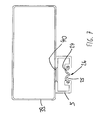
- dust extraction manifold 5 is mounted directly onto the male knife beam 39. Venturi holes 40 machined through the dust extraction manifold 5 align with holes machined through the male knife beam 39. The Venturi holes improve dust extraction by accelerating the airflow into the plenum chamber.
- the extractor fans start.
- the air being expelled from the plenum chamber is replaced in equal volume by air being sucked into the flexible hose.
- the volume of air being sucked into the flexible hose takes with it the dust created by the slitting action of the knives.
- Air passes through the flexible hose, into the manifold seal deflector, and into the dust extraction manifold.
- the extractor fans draw the air out of the dust extraction manifold into the plenum chamber. From the plenum chamber, the air/dust mixture is expelled from the extractor fans into the dust collection vessel.
Landscapes
- Life Sciences & Earth Sciences (AREA)
- Forests & Forestry (AREA)
- Engineering & Computer Science (AREA)
- Mechanical Engineering (AREA)
- Cleaning In General (AREA)
Description
- The invention relates to dust extraction systems and web slitters equipped therewith.
- The traditional dust extraction systems as used on the Applicant's slitter/rewinding machines include dust extraction hoses attached at one end to the male knife and at the other end to a fixed dust extraction manifold. A vacuum pump is provided to suck the dust away from the blade along the dust extraction hoses into the dust extraction manifold from where it is delivered to the dust collection vessel. The male knife may be positioned anywhere along the male knife beam within the limits imposed by the length of the dust extraction hose. Current dust extraction systems restrict the lateral movement of a knife blade during automatic knife positioning and manual knife positioning. The extraction hose of the prior art is secured in close proximity to the blade of the male knife and to the extraction manifold by respective hose clamps. These hose clamps are usually of the Chenny or Jubilee type. The extraction manifold is normally secured to the male knife beam.
- Whilst the prior art dust extraction systems have proved successful for a number of years, the number of knives fitted to the machine typically match the number of distinct extraction manifold fittings provided. Consequently, when the customer wishes to add another knife he has to allow several hours downtime in order to modify the extraction manifold and then purchase the spare parts to attach a new knife to the manifold. Furthermore, when the customer wishes to remove a male knife, the revealed unused manifold connection must be blocked to maintain the vacuum created in the extraction manifold.
- Furthermore, due to their inherent structure, the prior art dust extraction systems require relatively unwieldy external hoses and clips. It is therefore a relatively complex operation even to replace a knife blade with another kind of knife blade. Furthermore, since a flexible hose is used to connect the male knife blade guard to the extraction manifold, the flexible hose is extended every time the male knife is engaged with the female knife or grooved roll and compressed every time the male knife is disengaged with the female knife or grooved roll. The constant deflection of the flexible hose makes hose failure a real possibility.
- Within the current design, the hose used to link the knife holder to the manifold restricts the movement of the knife thereby limiting the set-ups that can be achieved with standard hoses. Extended hoses can be used to overcome this restriction but the cost and complexity of handling the additional hose length safely is prohibitive.
- Finally, relatively noisy, heavy and complex vacuum pumps are required to create the suction in the manifold.
-
US-5,031, 494 discloses a device which defines the preamble ofclaim 1. - The invention is defined in
claim 1. This configuration is particularly advantageous because it avoids the traditional requirement of one hole in the manifold for a particular hose end. Instead of discrete positioning of the end of an extractor conduit, unlimited male knife positioning may be achieved in the elongate channel. The requirements for potentially fiddly and complex clips are avoided. The male knives may be added or removed quickly and simply without the need for extensive technical assistance or spare parts other than the extra male knife. - In a subsidiary aspect, the seal is formed from two oppositely positioned sealing strips; whereby, in use, the relatively low pressure in the extraction manifold combines with the relatively high ambient air pressure to push said portions against said head. This configuration is particularly advantageous since it allows the strips to be relatively straightforwardly parted for the removal of the head whilst at the same time allowing a tight fit on the extraction head. Furthermore, it allows the knife blade to be positioned in any appropriate position of the elongate channel. Consequently, downtime if any, for the replacement of a knife blade is kept to the minimum with little or no requirement for modification of the manifold.
- In a further subsidiary aspect, the sealing strip portions are bowed. This increases the surface area of contact between the inner portion of the sealing strips and the head of the extraction system.
- In a further subsidiary aspect, the head incorporates an upper aperture and laterally extending fins. This configuration is particularly advantageous in terms of allowing the parting of the sealing strips for the insertion or the removal of the head.
- In a further subsidiary aspect, the fins are tapered. This further improves the ability of the fins to be used in parting the sealing strips.
- In a further subsidiary aspect, the fins are tapered in varying width from an upper portion of the fins to a lower portion of the fins. This further improves the ability of the fins being used to part the sealing strips.
- In a further subsidiary aspect, the fins decrease in thickness in the lateral direction. This provides a relatively pointed lateral extremity for the fins further facilitating the parting of the sealing strips.
- In a further subsidiary aspect, the fins are rounded. This configuration is particularly advantageous in terms of removing the sharp edges which may otherwise damage the air tightness of the extraction manifold.
- In a further subsidiary aspect, the extractor conduit incorporates a rigid telescopic portion. This configuration is particularly advantageous as it limits the degree of motion other than in the telescopic direction. In preferred embodiments, the internal surfaces of the rigid telescopic portion are relatively smooth which reduces the level of turbulence and consequently noise during the suction process.
- In a further subsidiary aspect, both the extraction manifold and the fan are mounted onto the male knife blade beam. This further improves the suction properties of the dust extraction system.
-
-
Figure 1 shows a side view of a male knife equipped with a first embodiment of the invention. -
Figure 2 shows a perspective view of a first embodiment of a dust extraction system. -
Figure 3 shows a cross-sectional view of a dust extraction manifold according to the first embodiment of the invention. -
Figure 4 shows a side view of a second embodiment of a dust extraction system. -
Figure 5 shows a front view of a male knife beam equipped with a plurality of extractor conduits at various locations along the length of the dust extraction manifold. -
Figure 6 shows a perspective view of the dust extraction manifold of the second embodiment of the invention. -
Figure 7 shows a cross-sectional view of the dust extraction manifold and male knife beam in accordance with a further embodiment of the invention. -
Figure 8 shows three separate configurations of the head of an extractor conduit in accordance with any of the embodiments of the invention. -
Figure 1 shows aknife blade assembly 1 equipped with a dust extraction system generally referenced 2. The dust extraction system incorporates an extractor conduit which at itsproximal extremity 3 is in an area adjacent the slitting operation and which at its distal extremity incorporates ahead 4 which engages withextraction manifold 5. Theextractor conduit 2 incorporates atelescoping extraction tube 6 and amanifold seal deflector 7. Thetelescoping extraction tube 6 extends laterally whilst themanifold seal deflector 7 extends upwardly. Thetelescoping extraction tube 6 and thedeflector 7 are joined together by atube section 8 provided at an angle. The deflector is secured onto themounting plate 9 by themounting plate 10. Releasable attachment means such asfasteners 11 and 12 immobilise the deflector relative to theplate 9. - The
telescoping extraction tube 6 incorporates a number of concentric tubular portions which slide relative to one another in order to achieve a lengthening or a shortening of the tube. Thecentral portion 13 of the telescoping extraction tube provides a relatively smooth internal surface. - The
manifold seal deflector 7 provides a substantially oblong internal cavity through which a mixture of air and dust travel upwards. The upper extremity of the deflector incorporates ahead 4 which has at least one but preferably two laterally extendingfins distal extremities Figure 8 wheredistal extremities distal extremities extremities - As can be best seen in
Figure 3 , the seal is formed of two sealingstrips dust extraction manifold 5 may be mounted onto themale knife beam 27 through releasable attachment means 28 and 29. The extraction manifold may be substantially U-shaped. Anaperture 30 may be provided between the extraction manifold and themale knife beam 27. Extractor fans may be provided on at least one side of the male knife beam as shown for example inFigure 5 where pumps 31 and 32 can draw air from the internal cavity of themale knife beam 27. - When the male knife is positioned, the tapered ends of the head part the seal gradually, preventing loss of air from the dust extraction manifold. Sealing is increased by flowing air (low pressure) in the dust extraction manifold exerting an upward "pull" on the seals forcing them against the head of the extraction system whilst the ambient air (high pressure) push the seal onto the head. The length of the taper offers least resistance and best sealing efficiency.
- The
dust extraction manifold 5 may be formed of twoparts Figure 3 , thedust extraction manifold 5 is mounted directly onto themale knife beam 27. The holes machined through the dust extraction manifold align with the holes machined through the male knife beam. - A control mechanism may be provided so that when the slitting operation starts, the extractor fans start. The air being expelled from the plenum chamber is replaced in equal volume by air being sucked into the telescoping extraction tube.
- The volume of air being sucked into the telescoping extraction tube takes with it the dust created by the slitting action of the knives. The air passes through the telescoping extraction tube into the manifold seal deflector and into the dust extraction manifold. The smooth internal surfaces of the telescoping extraction tube produce a fast, laminar air flow that maximises dust extraction. The extractor fans draw the air out of the dust extraction manifold into the plenum chamber. From the plenum chamber, the air/dust mixture is expelled from the extractor fans into a dust collection vessel (not shown). The dust extraction is illustrated by
arrows - As can be best seen in
Figure 5 , a number of deflectors may be positioned along a part of a dust extraction manifold. - A further embodiment of the invention is illustrated in
Figures 4 ,6 and7 . Identical numerical references to the first embodiment are employed throughout for simplicity other than for parts which differ from the corresponding parts in the first embodiment. InFigures 4 and6 , the telescoping extraction tube of the first embodiment has been replaced by aflexible hose 37 which connects the maleknife blade guard 38 to themanifold seal deflector 7. - As shown in
Figure 7 dust extraction manifold 5 is mounted directly onto themale knife beam 39. Venturi holes 40 machined through thedust extraction manifold 5 align with holes machined through themale knife beam 39. The Venturi holes improve dust extraction by accelerating the airflow into the plenum chamber. - When the machine starts, the extractor fans start. The air being expelled from the plenum chamber is replaced in equal volume by air being sucked into the flexible hose. The volume of air being sucked into the flexible hose takes with it the dust created by the slitting action of the knives. Air passes through the flexible hose, into the manifold seal deflector, and into the dust extraction manifold. The extractor fans draw the air out of the dust extraction manifold into the plenum chamber. From the plenum chamber, the air/dust mixture is expelled from the extractor fans into the dust collection vessel.
- In certain embodiments at least the following advantages are achieved:
- unlimited male knife positioning;
- simplified operation for changing the extraction hose attached to the male knife;
- male knives are added or removed quickly and simply without the need for technical assistance or spare parts other than the extra male knife;
- the number of male knives is only limited by the length of the male knife beam;
- a positive flow dust extraction manifold system;
- no external pipes or hoses connecting the male knives to the dust extraction manifold; and
- centrifugal blowers which are lighter and quieter.
Claims (10)
- A web slitter comprising a dust extraction system (2); said dust extraction system incorporating one or more slitting blades; said system comprising an extractor conduit (2) which at its proximal extremity (3) is in an area adjacent to the slitting operation and which at its distal extremity incorporates a head (4) which engages with an extraction manifold; an extractor fan for causing the flow of extracted dust from said proximal (3) to said distal extremity; and an elongate channel (26) with means for sealing said head (4) to said extraction manifold (5); whereby said head (4) may be positioned anywhere along said channel (26); characterised in that said manifold (5) is mounted onto a male knife beam (27); said manifold (5) incorporating Venturi holes (40) aligned with holes provided through said male knife blade beam (27).
- A system according to claim 1, wherein said seal is formed from two oppositely positioned sealing strip portions (24,25); whereby, in use, the relatively low pressure in the extraction manifold (5) combines with the relatively high ambient air pressure to push said portions (24, 25) against said head (4).
- A system according to claim 2, wherein said sealing strip portions (24,25) are bowed.
- A system according to any of the preceding claims, wherein said head (4) incorporates an upper aperture (30) and laterally extending fins (14,15).
- A system according to claim 4, wherein said fins (14,15) are tapered.
- A system according to claim 5, wherein said fins (14,15) are tapered and vary in width from an upper portion of said fins to a lower portion of said fins.
- A system according to either claim 5 or claim 6, wherein said fins (14,15) decrease in thickness in the lateral direction.
- A system according to any of claims 4 to 7, wherein said fins (14,15) are rounded.
- A system according to any of the preceding claims, wherein said extractor conduit (2) incorporates a rigid telescopic portion.
- A system according to any of the preceding claims, wherein both said extraction manifold (5) and said fan are mounted onto said male knife blade beam (27).
Priority Applications (1)
| Application Number | Priority Date | Filing Date | Title |
|---|---|---|---|
| EP20120197431 EP2743045B1 (en) | 2012-12-17 | 2012-12-17 | Dust extraction system and web slitters equipped therewith |
Applications Claiming Priority (1)
| Application Number | Priority Date | Filing Date | Title |
|---|---|---|---|
| EP20120197431 EP2743045B1 (en) | 2012-12-17 | 2012-12-17 | Dust extraction system and web slitters equipped therewith |
Publications (2)
| Publication Number | Publication Date |
|---|---|
| EP2743045A1 EP2743045A1 (en) | 2014-06-18 |
| EP2743045B1 true EP2743045B1 (en) | 2015-01-28 |
Family
ID=47559136
Family Applications (1)
| Application Number | Title | Priority Date | Filing Date |
|---|---|---|---|
| EP20120197431 Not-in-force EP2743045B1 (en) | 2012-12-17 | 2012-12-17 | Dust extraction system and web slitters equipped therewith |
Country Status (1)
| Country | Link |
|---|---|
| EP (1) | EP2743045B1 (en) |
Families Citing this family (1)
| Publication number | Priority date | Publication date | Assignee | Title |
|---|---|---|---|---|
| CN108068152B (en) * | 2017-12-05 | 2019-11-05 | 安徽依采妮纤维材料科技有限公司 | A kind of cutting machine for automobile interior decoration processing |
Family Cites Families (1)
| Publication number | Priority date | Publication date | Assignee | Title |
|---|---|---|---|---|
| US5031494A (en) * | 1990-01-10 | 1991-07-16 | Kampf Gmbh & Co. Maschinenfabrik | Web processing machine having at least one web and roll and a slitter for said web |
-
2012
- 2012-12-17 EP EP20120197431 patent/EP2743045B1/en not_active Not-in-force
Also Published As
| Publication number | Publication date |
|---|---|
| EP2743045A1 (en) | 2014-06-18 |
Similar Documents
| Publication | Publication Date | Title |
|---|---|---|
| US9867913B2 (en) | Suction device for surgical instruments | |
| EP2701568B1 (en) | Liquid aspirator for drawing off and sucking up liquids | |
| US11293293B2 (en) | Turbomachines that include a casing treatment | |
| US8118942B2 (en) | Dust removal apparatus and method | |
| EP2743045A1 (en) | Dust extraction system and web slitters equipped therewith | |
| EP2378132A1 (en) | Electric blower and electric vacuum cleaner utilizing the same | |
| JP5126839B2 (en) | Tea leaf picking device | |
| EP2937288B1 (en) | Inlet tube design | |
| US10266359B2 (en) | Apparatus and method for web transfer with an airguide | |
| JP4785666B2 (en) | Tea branch and leaf transfer device and tea cutting device having the same | |
| EP2425902B1 (en) | Dust-removing apparatus | |
| US20130061422A1 (en) | Multi-operational mode fluid extractors and associated methods of use and manufacture | |
| WO2014037227A1 (en) | Impingement tube for gas turbine vane with a partition wall | |
| EP2975347A1 (en) | System for drying an extrudate exiting a calibration tank | |
| JP2014202113A (en) | Ejector used in blower | |
| CN1695534A (en) | Nozzle for vaccum cleaner | |
| CN106321155B (en) | Gas turbine blade | |
| US7557323B2 (en) | Wire retrieving device for cutting machine | |
| CN210164695U (en) | Fan structure and range hood applying same | |
| US20140154118A1 (en) | Power Tool with Peristaltic Pump | |
| JP5008706B2 (en) | Dust remover | |
| CN213839045U (en) | Axial fan convenient to installation | |
| US11667387B2 (en) | Ice protection and boundary layer suction system for an aircraft aerofoil | |
| TW202235355A (en) | Positioning device and positioning assembly for holding a flat flexible part, and sheet material processing machine | |
| JP2015083817A (en) | Air duct used in blower device and dust collector |
Legal Events
| Date | Code | Title | Description |
|---|---|---|---|
| PUAI | Public reference made under article 153(3) epc to a published international application that has entered the european phase |
Free format text: ORIGINAL CODE: 0009012 |
|
| 17P | Request for examination filed |
Effective date: 20130703 |
|
| AK | Designated contracting states |
Kind code of ref document: A1 Designated state(s): AL AT BE BG CH CY CZ DE DK EE ES FI FR GB GR HR HU IE IS IT LI LT LU LV MC MK MT NL NO PL PT RO RS SE SI SK SM TR |
|
| AX | Request for extension of the european patent |
Extension state: BA ME |
|
| GRAP | Despatch of communication of intention to grant a patent |
Free format text: ORIGINAL CODE: EPIDOSNIGR1 |
|
| RIC1 | Information provided on ipc code assigned before grant |
Ipc: B26D 1/24 20060101ALN20140925BHEP Ipc: B26D 7/18 20060101AFI20140925BHEP |
|
| INTG | Intention to grant announced |
Effective date: 20141013 |
|
| GRAS | Grant fee paid |
Free format text: ORIGINAL CODE: EPIDOSNIGR3 |
|
| GRAA | (expected) grant |
Free format text: ORIGINAL CODE: 0009210 |
|
| AK | Designated contracting states |
Kind code of ref document: B1 Designated state(s): AL AT BE BG CH CY CZ DE DK EE ES FI FR GB GR HR HU IE IS IT LI LT LU LV MC MK MT NL NO PL PT RO RS SE SI SK SM TR |
|
| REG | Reference to a national code |
Ref country code: GB Ref legal event code: FG4D |
|
| REG | Reference to a national code |
Ref country code: CH Ref legal event code: EP |
|
| REG | Reference to a national code |
Ref country code: IE Ref legal event code: FG4D |
|
| REG | Reference to a national code |
Ref country code: DE Ref legal event code: R096 Ref document number: 602012005141 Country of ref document: DE Effective date: 20150312 |
|
| REG | Reference to a national code |
Ref country code: AT Ref legal event code: REF Ref document number: 708031 Country of ref document: AT Kind code of ref document: T Effective date: 20150315 |
|
| REG | Reference to a national code |
Ref country code: AT Ref legal event code: MK05 Ref document number: 708031 Country of ref document: AT Kind code of ref document: T Effective date: 20150128 |
|
| REG | Reference to a national code |
Ref country code: NL Ref legal event code: VDEP Effective date: 20150128 |
|
| REG | Reference to a national code |
Ref country code: LT Ref legal event code: MG4D |
|
| PG25 | Lapsed in a contracting state [announced via postgrant information from national office to epo] |
Ref country code: NO Free format text: LAPSE BECAUSE OF FAILURE TO SUBMIT A TRANSLATION OF THE DESCRIPTION OR TO PAY THE FEE WITHIN THE PRESCRIBED TIME-LIMIT Effective date: 20150428 Ref country code: HR Free format text: LAPSE BECAUSE OF FAILURE TO SUBMIT A TRANSLATION OF THE DESCRIPTION OR TO PAY THE FEE WITHIN THE PRESCRIBED TIME-LIMIT Effective date: 20150128 Ref country code: LT Free format text: LAPSE BECAUSE OF FAILURE TO SUBMIT A TRANSLATION OF THE DESCRIPTION OR TO PAY THE FEE WITHIN THE PRESCRIBED TIME-LIMIT Effective date: 20150128 Ref country code: FI Free format text: LAPSE BECAUSE OF FAILURE TO SUBMIT A TRANSLATION OF THE DESCRIPTION OR TO PAY THE FEE WITHIN THE PRESCRIBED TIME-LIMIT Effective date: 20150128 Ref country code: SE Free format text: LAPSE BECAUSE OF FAILURE TO SUBMIT A TRANSLATION OF THE DESCRIPTION OR TO PAY THE FEE WITHIN THE PRESCRIBED TIME-LIMIT Effective date: 20150128 Ref country code: BG Free format text: LAPSE BECAUSE OF FAILURE TO SUBMIT A TRANSLATION OF THE DESCRIPTION OR TO PAY THE FEE WITHIN THE PRESCRIBED TIME-LIMIT Effective date: 20150428 Ref country code: ES Free format text: LAPSE BECAUSE OF FAILURE TO SUBMIT A TRANSLATION OF THE DESCRIPTION OR TO PAY THE FEE WITHIN THE PRESCRIBED TIME-LIMIT Effective date: 20150128 |
|
| PG25 | Lapsed in a contracting state [announced via postgrant information from national office to epo] |
Ref country code: NL Free format text: LAPSE BECAUSE OF FAILURE TO SUBMIT A TRANSLATION OF THE DESCRIPTION OR TO PAY THE FEE WITHIN THE PRESCRIBED TIME-LIMIT Effective date: 20150128 Ref country code: LV Free format text: LAPSE BECAUSE OF FAILURE TO SUBMIT A TRANSLATION OF THE DESCRIPTION OR TO PAY THE FEE WITHIN THE PRESCRIBED TIME-LIMIT Effective date: 20150128 Ref country code: PL Free format text: LAPSE BECAUSE OF FAILURE TO SUBMIT A TRANSLATION OF THE DESCRIPTION OR TO PAY THE FEE WITHIN THE PRESCRIBED TIME-LIMIT Effective date: 20150128 Ref country code: IS Free format text: LAPSE BECAUSE OF FAILURE TO SUBMIT A TRANSLATION OF THE DESCRIPTION OR TO PAY THE FEE WITHIN THE PRESCRIBED TIME-LIMIT Effective date: 20150528 Ref country code: AT Free format text: LAPSE BECAUSE OF FAILURE TO SUBMIT A TRANSLATION OF THE DESCRIPTION OR TO PAY THE FEE WITHIN THE PRESCRIBED TIME-LIMIT Effective date: 20150128 Ref country code: RS Free format text: LAPSE BECAUSE OF FAILURE TO SUBMIT A TRANSLATION OF THE DESCRIPTION OR TO PAY THE FEE WITHIN THE PRESCRIBED TIME-LIMIT Effective date: 20150128 Ref country code: GR Free format text: LAPSE BECAUSE OF FAILURE TO SUBMIT A TRANSLATION OF THE DESCRIPTION OR TO PAY THE FEE WITHIN THE PRESCRIBED TIME-LIMIT Effective date: 20150429 |
|
| REG | Reference to a national code |
Ref country code: DE Ref legal event code: R097 Ref document number: 602012005141 Country of ref document: DE |
|
| PG25 | Lapsed in a contracting state [announced via postgrant information from national office to epo] |
Ref country code: RO Free format text: LAPSE BECAUSE OF FAILURE TO SUBMIT A TRANSLATION OF THE DESCRIPTION OR TO PAY THE FEE WITHIN THE PRESCRIBED TIME-LIMIT Effective date: 20150128 Ref country code: EE Free format text: LAPSE BECAUSE OF FAILURE TO SUBMIT A TRANSLATION OF THE DESCRIPTION OR TO PAY THE FEE WITHIN THE PRESCRIBED TIME-LIMIT Effective date: 20150128 Ref country code: CZ Free format text: LAPSE BECAUSE OF FAILURE TO SUBMIT A TRANSLATION OF THE DESCRIPTION OR TO PAY THE FEE WITHIN THE PRESCRIBED TIME-LIMIT Effective date: 20150128 Ref country code: SK Free format text: LAPSE BECAUSE OF FAILURE TO SUBMIT A TRANSLATION OF THE DESCRIPTION OR TO PAY THE FEE WITHIN THE PRESCRIBED TIME-LIMIT Effective date: 20150128 Ref country code: DK Free format text: LAPSE BECAUSE OF FAILURE TO SUBMIT A TRANSLATION OF THE DESCRIPTION OR TO PAY THE FEE WITHIN THE PRESCRIBED TIME-LIMIT Effective date: 20150128 |
|
| PLBE | No opposition filed within time limit |
Free format text: ORIGINAL CODE: 0009261 |
|
| STAA | Information on the status of an ep patent application or granted ep patent |
Free format text: STATUS: NO OPPOSITION FILED WITHIN TIME LIMIT |
|
| 26N | No opposition filed |
Effective date: 20151029 |
|
| PGFP | Annual fee paid to national office [announced via postgrant information from national office to epo] |
Ref country code: IT Payment date: 20151231 Year of fee payment: 4 |
|
| PG25 | Lapsed in a contracting state [announced via postgrant information from national office to epo] |
Ref country code: SI Free format text: LAPSE BECAUSE OF FAILURE TO SUBMIT A TRANSLATION OF THE DESCRIPTION OR TO PAY THE FEE WITHIN THE PRESCRIBED TIME-LIMIT Effective date: 20150128 |
|
| PG25 | Lapsed in a contracting state [announced via postgrant information from national office to epo] |
Ref country code: BE Free format text: LAPSE BECAUSE OF FAILURE TO SUBMIT A TRANSLATION OF THE DESCRIPTION OR TO PAY THE FEE WITHIN THE PRESCRIBED TIME-LIMIT Effective date: 20150128 |
|
| PG25 | Lapsed in a contracting state [announced via postgrant information from national office to epo] |
Ref country code: MC Free format text: LAPSE BECAUSE OF FAILURE TO SUBMIT A TRANSLATION OF THE DESCRIPTION OR TO PAY THE FEE WITHIN THE PRESCRIBED TIME-LIMIT Effective date: 20150128 Ref country code: LU Free format text: LAPSE BECAUSE OF FAILURE TO SUBMIT A TRANSLATION OF THE DESCRIPTION OR TO PAY THE FEE WITHIN THE PRESCRIBED TIME-LIMIT Effective date: 20151217 |
|
| REG | Reference to a national code |
Ref country code: CH Ref legal event code: PL |
|
| REG | Reference to a national code |
Ref country code: IE Ref legal event code: MM4A |
|
| REG | Reference to a national code |
Ref country code: FR Ref legal event code: ST Effective date: 20160831 |
|
| PG25 | Lapsed in a contracting state [announced via postgrant information from national office to epo] |
Ref country code: CH Free format text: LAPSE BECAUSE OF NON-PAYMENT OF DUE FEES Effective date: 20151231 Ref country code: IE Free format text: LAPSE BECAUSE OF NON-PAYMENT OF DUE FEES Effective date: 20151217 Ref country code: LI Free format text: LAPSE BECAUSE OF NON-PAYMENT OF DUE FEES Effective date: 20151231 |
|
| PG25 | Lapsed in a contracting state [announced via postgrant information from national office to epo] |
Ref country code: FR Free format text: LAPSE BECAUSE OF NON-PAYMENT OF DUE FEES Effective date: 20151231 |
|
| PG25 | Lapsed in a contracting state [announced via postgrant information from national office to epo] |
Ref country code: SM Free format text: LAPSE BECAUSE OF FAILURE TO SUBMIT A TRANSLATION OF THE DESCRIPTION OR TO PAY THE FEE WITHIN THE PRESCRIBED TIME-LIMIT Effective date: 20150128 Ref country code: HU Free format text: LAPSE BECAUSE OF FAILURE TO SUBMIT A TRANSLATION OF THE DESCRIPTION OR TO PAY THE FEE WITHIN THE PRESCRIBED TIME-LIMIT; INVALID AB INITIO Effective date: 20121217 |
|
| PG25 | Lapsed in a contracting state [announced via postgrant information from national office to epo] |
Ref country code: CY Free format text: LAPSE BECAUSE OF FAILURE TO SUBMIT A TRANSLATION OF THE DESCRIPTION OR TO PAY THE FEE WITHIN THE PRESCRIBED TIME-LIMIT Effective date: 20150128 |
|
| PG25 | Lapsed in a contracting state [announced via postgrant information from national office to epo] |
Ref country code: MT Free format text: LAPSE BECAUSE OF FAILURE TO SUBMIT A TRANSLATION OF THE DESCRIPTION OR TO PAY THE FEE WITHIN THE PRESCRIBED TIME-LIMIT Effective date: 20150128 |
|
| PG25 | Lapsed in a contracting state [announced via postgrant information from national office to epo] |
Ref country code: IT Free format text: LAPSE BECAUSE OF NON-PAYMENT OF DUE FEES Effective date: 20161217 |
|
| PG25 | Lapsed in a contracting state [announced via postgrant information from national office to epo] |
Ref country code: MK Free format text: LAPSE BECAUSE OF FAILURE TO SUBMIT A TRANSLATION OF THE DESCRIPTION OR TO PAY THE FEE WITHIN THE PRESCRIBED TIME-LIMIT Effective date: 20150128 Ref country code: PT Free format text: LAPSE BECAUSE OF FAILURE TO SUBMIT A TRANSLATION OF THE DESCRIPTION OR TO PAY THE FEE WITHIN THE PRESCRIBED TIME-LIMIT Effective date: 20150128 |
|
| PG25 | Lapsed in a contracting state [announced via postgrant information from national office to epo] |
Ref country code: AL Free format text: LAPSE BECAUSE OF FAILURE TO SUBMIT A TRANSLATION OF THE DESCRIPTION OR TO PAY THE FEE WITHIN THE PRESCRIBED TIME-LIMIT Effective date: 20150128 Ref country code: TR Free format text: LAPSE BECAUSE OF FAILURE TO SUBMIT A TRANSLATION OF THE DESCRIPTION OR TO PAY THE FEE WITHIN THE PRESCRIBED TIME-LIMIT Effective date: 20150128 |
|
| PGFP | Annual fee paid to national office [announced via postgrant information from national office to epo] |
Ref country code: GB Payment date: 20211214 Year of fee payment: 10 |
|
| PGFP | Annual fee paid to national office [announced via postgrant information from national office to epo] |
Ref country code: DE Payment date: 20211230 Year of fee payment: 10 |
|
| REG | Reference to a national code |
Ref country code: DE Ref legal event code: R119 Ref document number: 602012005141 Country of ref document: DE |
|
| GBPC | Gb: european patent ceased through non-payment of renewal fee |
Effective date: 20221217 |
|
| PG25 | Lapsed in a contracting state [announced via postgrant information from national office to epo] |
Ref country code: GB Free format text: LAPSE BECAUSE OF NON-PAYMENT OF DUE FEES Effective date: 20221217 Ref country code: DE Free format text: LAPSE BECAUSE OF NON-PAYMENT OF DUE FEES Effective date: 20230701 |