EP2742811A1 - Device for transferring pieces of filter or cigarette rod - Google Patents
Device for transferring pieces of filter or cigarette rod Download PDFInfo
- Publication number
- EP2742811A1 EP2742811A1 EP13195936.3A EP13195936A EP2742811A1 EP 2742811 A1 EP2742811 A1 EP 2742811A1 EP 13195936 A EP13195936 A EP 13195936A EP 2742811 A1 EP2742811 A1 EP 2742811A1
- Authority
- EP
- European Patent Office
- Prior art keywords
- shaft
- rotation
- axis
- sleeve
- transfer device
- Prior art date
- Legal status (The legal status is an assumption and is not a legal conclusion. Google has not performed a legal analysis and makes no representation as to the accuracy of the status listed.)
- Granted
Links
- 235000019504 cigarettes Nutrition 0.000 title claims abstract description 17
- 230000005540 biological transmission Effects 0.000 claims abstract description 22
- 230000033001 locomotion Effects 0.000 claims abstract description 22
- 230000003134 recirculating effect Effects 0.000 claims description 2
- 230000000694 effects Effects 0.000 description 2
- 230000008878 coupling Effects 0.000 description 1
- 238000010168 coupling process Methods 0.000 description 1
- 238000005859 coupling reaction Methods 0.000 description 1
- 238000010438 heat treatment Methods 0.000 description 1
- 238000005096 rolling process Methods 0.000 description 1
Images

Classifications
-
- A—HUMAN NECESSITIES
- A24—TOBACCO; CIGARS; CIGARETTES; SIMULATED SMOKING DEVICES; SMOKERS' REQUISITES
- A24C—MACHINES FOR MAKING CIGARS OR CIGARETTES
- A24C5/00—Making cigarettes; Making tipping materials for, or attaching filters or mouthpieces to, cigars or cigarettes
- A24C5/32—Separating, ordering, counting or examining cigarettes; Regulating the feeding of tobacco according to rod or cigarette condition
- A24C5/322—Transporting cigarettes during manufacturing
- A24C5/326—Transporting cigarettes during manufacturing with lateral transferring means
Definitions
- This invention relates to a device for transferring pieces of filter or cigarette rod.
- Prior art transfer devices of this kind are used in cigarette making machines to transfer pieces of filter rod from a pickup station to a release station where the pieces of filter rod are combined with respective pieces of cigarette rod to make finished cigarettes.
- These devices basically comprise a supporting drum which revolves about a main axis of rotation and a plurality of carrier elements or satellite elements, each mounted rotatably on the supporting drum in such a way as to rotate relative thereto about a respective axis of rotation which is parallel to the main axis.
- Each satellite element supports a gripper head which rotates about an axis of rotation also parallel to the main axis and which is movable, as the drum revolves, between a configuration for picking up the filters at the pickup station and a configuration for releasing the filters at the release station.
- each gripper head has a pair of seats in which respective pieces of filter or cigarette rod are held by suction during transfer between the pickup station and the release station.
- each seat of each gripper head remains parallel to itself for each angular position of the drum.
- the rotation of the movable carrier elements and of the gripper heads about the respective axes of rotation is accomplished through a transmission system driven by the rotation of the supporting drum and housed therein.
- the transmission system comprises a plurality of gears movable with reciprocating or uniform rotational motion and, in particular, at least one pair of gears for each movable carrier element, whose motion produces noise and vibrations causing imprecise positioning of the gripper heads.
- gear teeth are subject to wear and heating which cause further slack to be taken into account when assembling and setting up the transmission system.
- the main technical purpose of this invention is to propose a device for transferring pieces of filter or cigarette rod which is free of the above-mentioned disadvantages.
- this invention has for an aim to propose a device for transferring pieces of filter or cigarette rod which is structurally simpler, and thus easier to assemble and less expensive, than devices used for the same purpose known in the prior art.
- the numeral 1 denotes a device for transferring pieces of filter rod 2 or of cigarette rod.
- the device 1 is preferably mounted on a cigarette making machine capable of operating simultaneously on two continuous filter rods advancing in parallel with each other.
- the device 1 transfers a pair of pieces 2 from a pickup station 7 to a release station 8.
- the pieces 2 of filter obtained by cutting continuous filter rods, are picked up and at the release station 8, the pieces 2 of filter rod are combined with respective pieces of cigarette rod.
- the transfer device 1 comprises a supporting drum 3 mounted rotatably about an axis of rotation A1.
- the drum 3 comprises at least one satellite element 4 having a respective gripper head 5 for picking up at least one piece 2 of filter rod.
- each gripper head 5 is equipped with a pair of seats 6 for simultaneously holding and transferring a pair of pieces 2.
- the drum 3 comprises a plurality of satellite elements 4 which are equispaced from each other along the periphery of the drum 3 itself.
- the satellite element 4 is driven in rotation by the drum 3, thus rotating about the first axis of rotation A1.
- the satellite element 4 also rotates about its own axis of rotation, referred to as second axis of rotation A2, parallel to the first axis of rotation A1.
- the transfer device 1 comprises movement means 9 for driving the satellite elements 4 and able to impart rotation to the satellite element 9 itself about the axis of rotation thereof, that is, about the second axis of rotation A2, as the drum 3 revolves about the first axis of rotation A1.
- each satellite element 2 is rotated about the first axis of rotation A1 by the action of the drum 3 and is also driven in rotation about its own axis of rotation, that is the second axis of rotation A2, by the action of the respective movement means 9.
- the movement means 9 comprise a transmission unit 19 and an actuator member 21 associated with the transmission unit 19.
- the transmission unit 19 comprises a sleeve 10 connected to the satellite element 4 and a shaft 11 movable along a direction parallel to its own main axis B, housed at least partly in the sleeve 10 and screwably engaged therewith by a helical profile 20. More specifically, the actuator member 21 is engaged with the shaft 11 of the transmission unit 19.
- the sleeve 10 has an internal chamber 13 which receives the shaft 11 in such a way as to surround at least the part of it which is screwably engaged therewith.
- the shaft 11 has on its outside surface a splined guide 14 defining the helical profile 20 of predetermined pitch P.
- the internal chamber 13 of the sleeve 10 also has a helical profile, which matches the helical profile of the splined guide 14 of the shaft 11.
- a plurality of spherical elements 15 are inserted in the splined guide 14 in such a way as to be interposed between the shaft 11 and the sleeve 10.
- the spherical elements 15, by rolling, allow the sleeve 10 and the shaft 11 to move relative to each other.
- the coupling between the shaft 11 and the sleeve 10 through the agency of the helical profile 20 allows the translational or linear motion of the shaft 11 to be converted into the rotational motion of the sleeve 10.
- the helical profile imparts helical motion composed of translational motion and rotational motion, so that translation is accomplished by the shaft 11 and rotation by the sleeve 10.
- the satellite element 4 and the sleeve 10 are coaxial parts, so that a rotation of the sleeve 10 corresponds to a rotation of the respective satellite element 4.
- the satellite element 4 is connected directly to the sleeve 10, without any transmission element being interposed between them.
- the transmission unit 19 comprises a bush 16 which is rotatably coupled to the sleeve 10.
- the bush 16 defines a first locking element by which the sleeve 10 is locked to the supporting drum 3.
- the bush 16 prevents the sleeve 10 from being translated relative to the selfsame shaft 11 along a direction parallel to the main axis B.
- the transmission unit 19 comprises a tube 17 which is slidably coupled to the shaft 11.
- the tube 17 defines a second locking element by which the shaft 11 is locked to the supporting drum 3.
- the tube 17 prevents it from rotating about the main axis B of the selfsame shaft 11.
- cylindrical shaft 11 and the sleeve 10 respectively define a threaded shaft and a lead nut of a recirculating ball screw assembly 18.
- the translational drive is imparted to the shaft 11 through the actuator member 21.
- the actuator member 21 comprises a cam 12, which rotates about the first axis of rotation A1 of the drum 3.
- the cam 12 has a profile for engaging with the shaft 11 with at least a first shaped stretch able to impart a translational movement to the selfsame shaft 11 in such a way that the gripper head 5 of the satellite element 4 is kept parallel to itself, according to an operating configuration, for each angular position of the drum 3 between the pickup station 7 and the release station 8.
- the respective seats 6 maintain their positions in respective horizontal planes.
- the transmission unit 19 allow gripper heads 5 of the satellite elements 4 to remain parallel to themselves, that is to say, do the respective seats 6 maintain their positions in respective horizontal planes, for each angular position of the drum 3, unlike the prior art, where the gripper heads 5 remained parallel to themselves in all the angular positions of the drum 3 during its rotation.
- each of the gripper heads 5 is rotated about its respective second axis of rotation A2 to return to its operating configuration.
- the cam 12 has a profile by which it engages the shaft 11 and which has at least a second stretch which is shaped to impart a translational movement such that from the release station 8 to the pickup station 7, the gripper head 5 of the satellite element 4 is returned to its operating configuration at the pickup station 7 by rotation about its respective second axis of rotation A2.
- the engagement profiles of the cam 12 are shaped stretches, each having a certain inclination to the vertical of the cam 12.
- the engagement profiles of the cam 12 are shaped in such a way as to cause the shaft 11 to advance in parallel to the main axis B in a first direction, indicated by the arrow F1, and in a second direction, indicated by the arrow F2, opposite to the first direction.
- the rotation of the satellite element 4, connected to the respective sleeve 10, is a function of the pitch P of the helical guide 14 formed on the cylindrical shaft 11.
- a quarter of the helicoid pitch corresponds to a rotation through approximately 90 sexagesimal degrees of the sleeve 10, and thus of the satellite element 4.
- the pitch of the helical guide is as large as possible in order to minimize positioning errors.
- a first advantage is the constructional simplicity of the transfer device 1 because the transmission unit 19 of each satellite element 4 is no longer housed inside the drum 3, as in the prior art, but is mounted peripherally of the drum 3, in alignment with the respective satellite element 4. This does away with the need for angle transmission devices and thus allows significantly higher precision.
- the transmission unit 19 such as the shaft 11 and the sleeve 10, are used in place, for example, of gears and appreciably reduce vibrations and noise.
Landscapes
- Manufacturing Of Cigar And Cigarette Tobacco (AREA)
- Cigarettes, Filters, And Manufacturing Of Filters (AREA)
Abstract
Description
- This invention relates to a device for transferring pieces of filter or cigarette rod.
- Prior art transfer devices of this kind are used in cigarette making machines to transfer pieces of filter rod from a pickup station to a release station where the pieces of filter rod are combined with respective pieces of cigarette rod to make finished cigarettes.
- These devices basically comprise a supporting drum which revolves about a main axis of rotation and a plurality of carrier elements or satellite elements, each mounted rotatably on the supporting drum in such a way as to rotate relative thereto about a respective axis of rotation which is parallel to the main axis.
- Each satellite element supports a gripper head which rotates about an axis of rotation also parallel to the main axis and which is movable, as the drum revolves, between a configuration for picking up the filters at the pickup station and a configuration for releasing the filters at the release station.
- Usually, each gripper head has a pair of seats in which respective pieces of filter or cigarette rod are held by suction during transfer between the pickup station and the release station.
- Further, as the drum revolves, each seat of each gripper head remains parallel to itself for each angular position of the drum.
- The rotation of the movable carrier elements and of the gripper heads about the respective axes of rotation is accomplished through a transmission system driven by the rotation of the supporting drum and housed therein.
- The prior art transmission systems have several disadvantages, however.
- In effect, the transmission system comprises a plurality of gears movable with reciprocating or uniform rotational motion and, in particular, at least one pair of gears for each movable carrier element, whose motion produces noise and vibrations causing imprecise positioning of the gripper heads.
- Moreover, the gear teeth are subject to wear and heating which cause further slack to be taken into account when assembling and setting up the transmission system.
- From the above it may be inferred that the prior art system are extremely complex, difficult to assemble - because they require painstakingly meticulous adjustments - and relatively high in cost.
- In this context, the main technical purpose of this invention is to propose a device for transferring pieces of filter or cigarette rod which is free of the above-mentioned disadvantages.
- More specifically, this invention has for an aim to propose a device for transferring pieces of filter or cigarette rod which is structurally simpler, and thus easier to assemble and less expensive, than devices used for the same purpose known in the prior art.
- The technical purpose and aims specified are substantially achieved by a device for transferring pieces of filter or cigarette rod as set out in the independent claim 1.
- Further features of the invention and its advantages are more apparent in the non-limiting description below, with reference to a preferred but non-exclusive embodiment of a transfer system, as illustrated in the accompanying drawings, in which:
-
Figure 1 is a schematic front view of a device for transferring pieces of filter or cigarette rod according to this invention; -
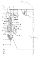
Figure 2 illustrates the device ofFigure 1 in a sectional view, with some parts cut away in order to better illustrate others. - With reference to
Figure 1 , the numeral 1 denotes a device for transferring pieces offilter rod 2 or of cigarette rod. - The device 1 is preferably mounted on a cigarette making machine capable of operating simultaneously on two continuous filter rods advancing in parallel with each other.
- The device 1 transfers a pair of
pieces 2 from apickup station 7 to a release station 8. - More specifically, at the
pickup station 7, thepieces 2 of filter, obtained by cutting continuous filter rods, are picked up and at the release station 8, thepieces 2 of filter rod are combined with respective pieces of cigarette rod. - The transfer device 1 comprises a supporting
drum 3 mounted rotatably about an axis of rotation A1. - The
drum 3 comprises at least onesatellite element 4 having arespective gripper head 5 for picking up at least onepiece 2 of filter rod. - Preferably, each
gripper head 5 is equipped with a pair ofseats 6 for simultaneously holding and transferring a pair ofpieces 2. - In the embodiment illustrated, the
drum 3 comprises a plurality ofsatellite elements 4 which are equispaced from each other along the periphery of thedrum 3 itself. - The
satellite element 4 is driven in rotation by thedrum 3, thus rotating about the first axis of rotation A1. - The
satellite element 4 also rotates about its own axis of rotation, referred to as second axis of rotation A2, parallel to the first axis of rotation A1. - The transfer device 1 comprises movement means 9 for driving the
satellite elements 4 and able to impart rotation to thesatellite element 9 itself about the axis of rotation thereof, that is, about the second axis of rotation A2, as thedrum 3 revolves about the first axis of rotation A1. - Thus, each
satellite element 2 is rotated about the first axis of rotation A1 by the action of thedrum 3 and is also driven in rotation about its own axis of rotation, that is the second axis of rotation A2, by the action of the respective movement means 9. - According to the invention, the movement means 9 comprise a
transmission unit 19 and anactuator member 21 associated with thetransmission unit 19. - The
transmission unit 19 comprises asleeve 10 connected to thesatellite element 4 and ashaft 11 movable along a direction parallel to its own main axis B, housed at least partly in thesleeve 10 and screwably engaged therewith by ahelical profile 20. More specifically, theactuator member 21 is engaged with theshaft 11 of thetransmission unit 19. - The
sleeve 10 has aninternal chamber 13 which receives theshaft 11 in such a way as to surround at least the part of it which is screwably engaged therewith. - More specifically, the
shaft 11 has on its outside surface asplined guide 14 defining thehelical profile 20 of predetermined pitch P. - The
internal chamber 13 of thesleeve 10 also has a helical profile, which matches the helical profile of thesplined guide 14 of theshaft 11. - A plurality of
spherical elements 15 are inserted in thesplined guide 14 in such a way as to be interposed between theshaft 11 and thesleeve 10. - Advantageously, the
spherical elements 15, by rolling, allow thesleeve 10 and theshaft 11 to move relative to each other. - The coupling between the
shaft 11 and thesleeve 10 through the agency of thehelical profile 20 allows the translational or linear motion of theshaft 11 to be converted into the rotational motion of thesleeve 10. - In effect, the helical profile imparts helical motion composed of translational motion and rotational motion, so that translation is accomplished by the
shaft 11 and rotation by thesleeve 10. Preferably, thesatellite element 4 and thesleeve 10 are coaxial parts, so that a rotation of thesleeve 10 corresponds to a rotation of therespective satellite element 4. - Advantageously, the
satellite element 4 is connected directly to thesleeve 10, without any transmission element being interposed between them. - In order to constrain the
sleeve 10 to be only rotated, thetransmission unit 19 comprises abush 16 which is rotatably coupled to thesleeve 10. - The
bush 16 defines a first locking element by which thesleeve 10 is locked to the supportingdrum 3. - That way, while the
shaft 11 is translated, thebush 16 prevents thesleeve 10 from being translated relative to theselfsame shaft 11 along a direction parallel to the main axis B. - In order to constrain the
shaft 11 to be only translated, thetransmission unit 19 comprises atube 17 which is slidably coupled to theshaft 11. - The
tube 17 defines a second locking element by which theshaft 11 is locked to the supportingdrum 3. - That way, while the
shaft 11 is translated, thetube 17 prevents it from rotating about the main axis B of theselfsame shaft 11. - From what is described above, it follows that the
shaft 11 moves only by translational or linear motion along a direction parallel to the main axis B and that thesleeve 10 moves only by rotational motion about the main axis B. - In practice, the
cylindrical shaft 11 and thesleeve 10 respectively define a threaded shaft and a lead nut of a recirculatingball screw assembly 18. - The translational drive is imparted to the
shaft 11 through theactuator member 21. - The
actuator member 21 comprises acam 12, which rotates about the first axis of rotation A1 of thedrum 3. - The
cam 12 has a profile for engaging with theshaft 11 with at least a first shaped stretch able to impart a translational movement to theselfsame shaft 11 in such a way that thegripper head 5 of thesatellite element 4 is kept parallel to itself, according to an operating configuration, for each angular position of thedrum 3 between thepickup station 7 and the release station 8. - More precisely, with reference in particular to
Figure 1 , in the operating configuration of thegripper heads 7, therespective seats 6 maintain their positions in respective horizontal planes. Advantageously, only between thepickup station 7 and the release station 8 does thetransmission unit 19 allowgripper heads 5 of thesatellite elements 4 to remain parallel to themselves, that is to say, do therespective seats 6 maintain their positions in respective horizontal planes, for each angular position of thedrum 3, unlike the prior art, where thegripper heads 5 remained parallel to themselves in all the angular positions of thedrum 3 during its rotation. - In the circular sector following the release station 8, that is to say, while the gripper heads 5 travel from the release station 8 back to the
pickup station 7, each of thegripper heads 5 is rotated about its respective second axis of rotation A2 to return to its operating configuration. - The
cam 12 has a profile by which it engages theshaft 11 and which has at least a second stretch which is shaped to impart a translational movement such that from the release station 8 to thepickup station 7, thegripper head 5 of thesatellite element 4 is returned to its operating configuration at thepickup station 7 by rotation about its respective second axis of rotation A2. - In order to impart the translational movements, the engagement profiles of the
cam 12 are shaped stretches, each having a certain inclination to the vertical of thecam 12. - The engagement profiles of the
cam 12 are shaped in such a way as to cause theshaft 11 to advance in parallel to the main axis B in a first direction, indicated by the arrow F1, and in a second direction, indicated by the arrow F2, opposite to the first direction. - The rotation of the
satellite element 4, connected to therespective sleeve 10, is a function of the pitch P of thehelical guide 14 formed on thecylindrical shaft 11. - The rotation of the
sleeve 10 is in turn converted to translation to be imparted to theshaft 11 through the agency of the engagement profile of thecam 12. - Consequently, the translation of the
shaft 11 along its main axis B and the shaped profile of thecam 12 also depend on the pitch P of thehelical guide 14. - Preferably, a quarter of the helicoid pitch corresponds to a rotation through approximately 90 sexagesimal degrees of the
sleeve 10, and thus of thesatellite element 4. - Preferably, the pitch of the helical guide is as large as possible in order to minimize positioning errors.
- The invention as described above brings important advantages.
- A first advantage is the constructional simplicity of the transfer device 1 because the
transmission unit 19 of eachsatellite element 4 is no longer housed inside thedrum 3, as in the prior art, but is mounted peripherally of thedrum 3, in alignment with therespective satellite element 4. This does away with the need for angle transmission devices and thus allows significantly higher precision. - Furthermore, certain parts of the
transmission unit 19, such as theshaft 11 and thesleeve 10, are used in place, for example, of gears and appreciably reduce vibrations and noise. - Another advantage is given by the ease of assembly and setting up of the
transmission unit 19 andactuator member 21, since theshaft 11 and thesleeve 10 are pre-assembled and coupled to each other before being installed in the device 1. This, combined with the fact that these parts can advantageously be preloaded makes it possible to minimize slack during operation.
Claims (9)
- A device for transferring pieces of filter or cigarette rod, comprising a drum (3) revolving about a first axis of rotation (A1), at least one satellite element (4) comprising a respective gripper head (5) for picking up at least one piece of filter or cigarette rod (2) and which is movable between a pickup station (7) where the piece (2) is picked up and a release station (8) where the selfsame piece (2) is released; the satellite element (4) rotating about a second axis of rotation (A2) parallel to the first axis of rotation (A1); the transfer device (1) comprising movement means (9) for driving the satellite element (4) and being characterized in that the movement means (9) comprise a transmission unit (19) comprising a sleeve (10) connected to the satellite element (4) and a shaft (11) movable along a direction parallel to its own main axis (B), housed at least partly in the sleeve (10) and screwably engaged therewith by a helical profile (20), the movement means comprising an actuator member (21) associated with the transmission unit (19) and engaged with the shaft (11); the actuator member (21) causing translation of the shaft (11) along a direction parallel to the main axis (B); the translation, through the agency of the helical profile (20), in turn causing the sleeve (10) and the respective satellite element (4) to rotate about the second axis of rotation (A2).
- The transfer device according to claim 1, characterized in that the transmission unit (19) comprises a first locking element (16) by which the sleeve (10) is connected to the supporting drum (3); the first locking element (16) being rotatably coupled to the sleeve (10).
- The transfer device according to claim 1 or 2, characterized in that the transmission unit (19) comprises a second locking element (17) by which the shaft (11) is connected to the supporting drum (3); the shaft (11) being slidably coupled to the second locking element (17).
- The transfer device according to claim 3, characterized in that the actuator member (21) comprises a cam (12), rotatable about the first axis of rotation (A1) and having a profile for engaging with the shaft (11) with at least a first stretch shaped to impart a translational movement to the selfsame shaft (11) in such a way that the gripper head (5) of the satellite element (4) is kept parallel to itself, according to an operating configuration, for each angular position of the drum (3) between the pickup station (7) and the release station (8).
- The transfer device according to claim 4, characterized in that the cam (12) has a profile for engaging with the shaft (11) with at least a second stretch for imparting a translational movement to the selfsame shaft (11) in such a way that from the release station (8) to the pickup station (7), the gripper head (5) of the satellite element (4) is returned to its operating configuration at the pickup station (7).
- The transfer device according to claim 5, characterized in that from the release station (8) to the pickup station (7), the gripper head (5) of the respective satellite element (4) rotates about the second axis of rotation (A2).
- The transfer device according to any of the claims from 1 to 6, characterized in that the shaft (11) has on its outside surface a splined guide (14) defining the helical profile (20) of predetermined pitch (P); the rotation of the satellite element (4) being a function of the pitch (P) of the helical, splined guide (14).
- The transfer device according to claim 7, characterized in that the translation of the shaft (11) along its main axis (B) and the shaped profile of the cam (12) depend on the pitch (P) of the helical, splined guide (14).
- The transfer device according to any of the claims from 1 to 8, characterized in that the shaft (11) and the sleeve (10) respectively define a threaded shaft and a lead nut of a recirculating ball screw assembly (18).
Priority Applications (1)
| Application Number | Priority Date | Filing Date | Title |
|---|---|---|---|
| PL13195936T PL2742811T3 (en) | 2012-12-11 | 2013-12-05 | Device for transferring pieces of filter or cigarette rod |
Applications Claiming Priority (1)
| Application Number | Priority Date | Filing Date | Title |
|---|---|---|---|
| IT000664A ITBO20120664A1 (en) | 2012-12-11 | 2012-12-11 | TRANSFER DEVICE FOR FILTERS OR CIGARETTES. |
Publications (2)
| Publication Number | Publication Date |
|---|---|
| EP2742811A1 true EP2742811A1 (en) | 2014-06-18 |
| EP2742811B1 EP2742811B1 (en) | 2015-08-12 |
Family
ID=47683815
Family Applications (1)
| Application Number | Title | Priority Date | Filing Date |
|---|---|---|---|
| EP13195936.3A Not-in-force EP2742811B1 (en) | 2012-12-11 | 2013-12-05 | Device for transferring pieces of filter or cigarette rod |
Country Status (3)
| Country | Link |
|---|---|
| EP (1) | EP2742811B1 (en) |
| IT (1) | ITBO20120664A1 (en) |
| PL (1) | PL2742811T3 (en) |
Citations (5)
| Publication number | Priority date | Publication date | Assignee | Title |
|---|---|---|---|---|
| FR2516901A1 (en) * | 1981-11-24 | 1983-05-27 | Gd Spa | DEVICE FOR TRANSFERRING CIGARETTES |
| EP1561386A1 (en) * | 2004-02-03 | 2005-08-10 | G.D S.p.A. | A combination unit for the manufacture of tobacco products |
| EP1639907A1 (en) * | 2004-09-24 | 2006-03-29 | Hauni Maschinenbau Aktiengesellschaft | Device for transferring rod-like articles |
| EP2251283A1 (en) * | 2009-05-15 | 2010-11-17 | Hauni Maschinenbau Aktiengesellschaft | Conveyor device with vacuum suction |
| EP2505086A1 (en) * | 2011-03-28 | 2012-10-03 | G.D Societa' Per Azioni | Transfer or feed drum, with radial-arm-mounted operating heads, for filter or cigarette portions |
-
2012
- 2012-12-11 IT IT000664A patent/ITBO20120664A1/en unknown
-
2013
- 2013-12-05 EP EP13195936.3A patent/EP2742811B1/en not_active Not-in-force
- 2013-12-05 PL PL13195936T patent/PL2742811T3/en unknown
Patent Citations (5)
| Publication number | Priority date | Publication date | Assignee | Title |
|---|---|---|---|---|
| FR2516901A1 (en) * | 1981-11-24 | 1983-05-27 | Gd Spa | DEVICE FOR TRANSFERRING CIGARETTES |
| EP1561386A1 (en) * | 2004-02-03 | 2005-08-10 | G.D S.p.A. | A combination unit for the manufacture of tobacco products |
| EP1639907A1 (en) * | 2004-09-24 | 2006-03-29 | Hauni Maschinenbau Aktiengesellschaft | Device for transferring rod-like articles |
| EP2251283A1 (en) * | 2009-05-15 | 2010-11-17 | Hauni Maschinenbau Aktiengesellschaft | Conveyor device with vacuum suction |
| EP2505086A1 (en) * | 2011-03-28 | 2012-10-03 | G.D Societa' Per Azioni | Transfer or feed drum, with radial-arm-mounted operating heads, for filter or cigarette portions |
Also Published As
| Publication number | Publication date |
|---|---|
| ITBO20120664A1 (en) | 2014-06-12 |
| PL2742811T3 (en) | 2015-12-31 |
| EP2742811B1 (en) | 2015-08-12 |
Similar Documents
| Publication | Publication Date | Title |
|---|---|---|
| CN107813046B (en) | Support device for supporting tubes on a tube processing machine and related tube processing machine | |
| CN106232455A (en) | Steering column for motor vehicles | |
| US4483351A (en) | Turnaround device for rod-like articles, in particular cigarettes | |
| CN104818576A (en) | Variable-rail three-dimensional composite knitting and shaping machine with angular guide wheels | |
| EP2742811B1 (en) | Device for transferring pieces of filter or cigarette rod | |
| CN108789447A (en) | Mute needing machine device people and its permanent arc length inter-linked controlling method | |
| CN107520566A (en) | A kind welding machine | |
| CN105364191B (en) | Index adjusting mechanism and spiral bevel gear milling machine | |
| CN1933742A (en) | Device for producing cigarettes | |
| CN108613000A (en) | A kind of monitoring device that coverage is wide | |
| RU2649739C2 (en) | Support mechanism for rods manufacturing machines | |
| CN209050211U (en) | A kind of special gear axis hobbing device | |
| DE102013104708B4 (en) | Device for transferring rod-shaped smoking articles | |
| CN109533909A (en) | 90 degree of oblique balance wheel sorters | |
| CN107053251B (en) | Linear synchronous belt stretching device and method | |
| CN109129617A (en) | A kind of cutter device of plate | |
| JP2011527943A5 (en) | ||
| US9682417B2 (en) | Bending device and spring manufacturing machine | |
| CN110421042B (en) | Electric stay bar channeling equipment | |
| CN104889502A (en) | Large gear grinding machine grinding wheel rack rotation device and rotation control method thereof | |
| KR101846040B1 (en) | Apparatus for the movement of wire dispensing members used for winding coils of core components of dynamoelectric machines | |
| CN107750195B (en) | peeling machine for long products | |
| CN101077514A (en) | Device for line-returnedly bending a continuous wire rod | |
| CN205098985U (en) | Install in clamping device of carousel | |
| CN110026499A (en) | A kind of building bar forming machine equipment |
Legal Events
| Date | Code | Title | Description |
|---|---|---|---|
| PUAI | Public reference made under article 153(3) epc to a published international application that has entered the european phase |
Free format text: ORIGINAL CODE: 0009012 |
|
| 17P | Request for examination filed |
Effective date: 20131205 |
|
| AK | Designated contracting states |
Kind code of ref document: A1 Designated state(s): AL AT BE BG CH CY CZ DE DK EE ES FI FR GB GR HR HU IE IS IT LI LT LU LV MC MK MT NL NO PL PT RO RS SE SI SK SM TR |
|
| AX | Request for extension of the european patent |
Extension state: BA ME |
|
| R17P | Request for examination filed (corrected) |
Effective date: 20140625 |
|
| RBV | Designated contracting states (corrected) |
Designated state(s): AL AT BE BG CH CY CZ DE DK EE ES FI FR GB GR HR HU IE IS IT LI LT LU LV MC MK MT NL NO PL PT RO RS SE SI SK SM TR |
|
| GRAP | Despatch of communication of intention to grant a patent |
Free format text: ORIGINAL CODE: EPIDOSNIGR1 |
|
| RIC1 | Information provided on ipc code assigned before grant |
Ipc: A24C 5/32 20060101AFI20150219BHEP |
|
| INTG | Intention to grant announced |
Effective date: 20150318 |
|
| GRAS | Grant fee paid |
Free format text: ORIGINAL CODE: EPIDOSNIGR3 |
|
| GRAA | (expected) grant |
Free format text: ORIGINAL CODE: 0009210 |
|
| AK | Designated contracting states |
Kind code of ref document: B1 Designated state(s): AL AT BE BG CH CY CZ DE DK EE ES FI FR GB GR HR HU IE IS IT LI LT LU LV MC MK MT NL NO PL PT RO RS SE SI SK SM TR |
|
| REG | Reference to a national code |
Ref country code: GB Ref legal event code: FG4D |
|
| REG | Reference to a national code |
Ref country code: CH Ref legal event code: EP |
|
| REG | Reference to a national code |
Ref country code: AT Ref legal event code: REF Ref document number: 741329 Country of ref document: AT Kind code of ref document: T Effective date: 20150815 |
|
| REG | Reference to a national code |
Ref country code: IE Ref legal event code: FG4D |
|
| REG | Reference to a national code |
Ref country code: DE Ref legal event code: R096 Ref document number: 602013002628 Country of ref document: DE |
|
| REG | Reference to a national code |
Ref country code: PL Ref legal event code: T3 |
|
| REG | Reference to a national code |
Ref country code: LT Ref legal event code: MG4D |
|
| REG | Reference to a national code |
Ref country code: AT Ref legal event code: MK05 Ref document number: 741329 Country of ref document: AT Kind code of ref document: T Effective date: 20150812 |
|
| REG | Reference to a national code |
Ref country code: NL Ref legal event code: MP Effective date: 20150812 |
|
| PG25 | Lapsed in a contracting state [announced via postgrant information from national office to epo] |
Ref country code: GR Free format text: LAPSE BECAUSE OF FAILURE TO SUBMIT A TRANSLATION OF THE DESCRIPTION OR TO PAY THE FEE WITHIN THE PRESCRIBED TIME-LIMIT Effective date: 20151113 Ref country code: LT Free format text: LAPSE BECAUSE OF FAILURE TO SUBMIT A TRANSLATION OF THE DESCRIPTION OR TO PAY THE FEE WITHIN THE PRESCRIBED TIME-LIMIT Effective date: 20150812 Ref country code: NO Free format text: LAPSE BECAUSE OF FAILURE TO SUBMIT A TRANSLATION OF THE DESCRIPTION OR TO PAY THE FEE WITHIN THE PRESCRIBED TIME-LIMIT Effective date: 20151112 Ref country code: FI Free format text: LAPSE BECAUSE OF FAILURE TO SUBMIT A TRANSLATION OF THE DESCRIPTION OR TO PAY THE FEE WITHIN THE PRESCRIBED TIME-LIMIT Effective date: 20150812 Ref country code: LV Free format text: LAPSE BECAUSE OF FAILURE TO SUBMIT A TRANSLATION OF THE DESCRIPTION OR TO PAY THE FEE WITHIN THE PRESCRIBED TIME-LIMIT Effective date: 20150812 |
|
| PG25 | Lapsed in a contracting state [announced via postgrant information from national office to epo] |
Ref country code: PT Free format text: LAPSE BECAUSE OF FAILURE TO SUBMIT A TRANSLATION OF THE DESCRIPTION OR TO PAY THE FEE WITHIN THE PRESCRIBED TIME-LIMIT Effective date: 20151214 Ref country code: SE Free format text: LAPSE BECAUSE OF FAILURE TO SUBMIT A TRANSLATION OF THE DESCRIPTION OR TO PAY THE FEE WITHIN THE PRESCRIBED TIME-LIMIT Effective date: 20150812 Ref country code: AT Free format text: LAPSE BECAUSE OF FAILURE TO SUBMIT A TRANSLATION OF THE DESCRIPTION OR TO PAY THE FEE WITHIN THE PRESCRIBED TIME-LIMIT Effective date: 20150812 Ref country code: HR Free format text: LAPSE BECAUSE OF FAILURE TO SUBMIT A TRANSLATION OF THE DESCRIPTION OR TO PAY THE FEE WITHIN THE PRESCRIBED TIME-LIMIT Effective date: 20150812 Ref country code: RS Free format text: LAPSE BECAUSE OF FAILURE TO SUBMIT A TRANSLATION OF THE DESCRIPTION OR TO PAY THE FEE WITHIN THE PRESCRIBED TIME-LIMIT Effective date: 20150812 Ref country code: ES Free format text: LAPSE BECAUSE OF FAILURE TO SUBMIT A TRANSLATION OF THE DESCRIPTION OR TO PAY THE FEE WITHIN THE PRESCRIBED TIME-LIMIT Effective date: 20150812 Ref country code: IS Free format text: LAPSE BECAUSE OF FAILURE TO SUBMIT A TRANSLATION OF THE DESCRIPTION OR TO PAY THE FEE WITHIN THE PRESCRIBED TIME-LIMIT Effective date: 20151212 |
|
| PG25 | Lapsed in a contracting state [announced via postgrant information from national office to epo] |
Ref country code: NL Free format text: LAPSE BECAUSE OF FAILURE TO SUBMIT A TRANSLATION OF THE DESCRIPTION OR TO PAY THE FEE WITHIN THE PRESCRIBED TIME-LIMIT Effective date: 20150812 |
|
| PG25 | Lapsed in a contracting state [announced via postgrant information from national office to epo] |
Ref country code: IT Free format text: LAPSE BECAUSE OF FAILURE TO SUBMIT A TRANSLATION OF THE DESCRIPTION OR TO PAY THE FEE WITHIN THE PRESCRIBED TIME-LIMIT Effective date: 20150812 Ref country code: EE Free format text: LAPSE BECAUSE OF FAILURE TO SUBMIT A TRANSLATION OF THE DESCRIPTION OR TO PAY THE FEE WITHIN THE PRESCRIBED TIME-LIMIT Effective date: 20150812 Ref country code: DK Free format text: LAPSE BECAUSE OF FAILURE TO SUBMIT A TRANSLATION OF THE DESCRIPTION OR TO PAY THE FEE WITHIN THE PRESCRIBED TIME-LIMIT Effective date: 20150812 Ref country code: CZ Free format text: LAPSE BECAUSE OF FAILURE TO SUBMIT A TRANSLATION OF THE DESCRIPTION OR TO PAY THE FEE WITHIN THE PRESCRIBED TIME-LIMIT Effective date: 20150812 Ref country code: SK Free format text: LAPSE BECAUSE OF FAILURE TO SUBMIT A TRANSLATION OF THE DESCRIPTION OR TO PAY THE FEE WITHIN THE PRESCRIBED TIME-LIMIT Effective date: 20150812 |
|
| REG | Reference to a national code |
Ref country code: DE Ref legal event code: R097 Ref document number: 602013002628 Country of ref document: DE |
|
| PG25 | Lapsed in a contracting state [announced via postgrant information from national office to epo] |
Ref country code: RO Free format text: LAPSE BECAUSE OF FAILURE TO SUBMIT A TRANSLATION OF THE DESCRIPTION OR TO PAY THE FEE WITHIN THE PRESCRIBED TIME-LIMIT Effective date: 20150812 Ref country code: BE Free format text: LAPSE BECAUSE OF NON-PAYMENT OF DUE FEES Effective date: 20151231 |
|
| PLBE | No opposition filed within time limit |
Free format text: ORIGINAL CODE: 0009261 |
|
| STAA | Information on the status of an ep patent application or granted ep patent |
Free format text: STATUS: NO OPPOSITION FILED WITHIN TIME LIMIT |
|
| 26N | No opposition filed |
Effective date: 20160513 |
|
| PG25 | Lapsed in a contracting state [announced via postgrant information from national office to epo] |
Ref country code: MC Free format text: LAPSE BECAUSE OF FAILURE TO SUBMIT A TRANSLATION OF THE DESCRIPTION OR TO PAY THE FEE WITHIN THE PRESCRIBED TIME-LIMIT Effective date: 20150812 Ref country code: LU Free format text: LAPSE BECAUSE OF FAILURE TO SUBMIT A TRANSLATION OF THE DESCRIPTION OR TO PAY THE FEE WITHIN THE PRESCRIBED TIME-LIMIT Effective date: 20151205 |
|
| PG25 | Lapsed in a contracting state [announced via postgrant information from national office to epo] |
Ref country code: SI Free format text: LAPSE BECAUSE OF FAILURE TO SUBMIT A TRANSLATION OF THE DESCRIPTION OR TO PAY THE FEE WITHIN THE PRESCRIBED TIME-LIMIT Effective date: 20150812 |
|
| REG | Reference to a national code |
Ref country code: IE Ref legal event code: MM4A |
|
| REG | Reference to a national code |
Ref country code: FR Ref legal event code: ST Effective date: 20160831 |
|
| PG25 | Lapsed in a contracting state [announced via postgrant information from national office to epo] |
Ref country code: IE Free format text: LAPSE BECAUSE OF NON-PAYMENT OF DUE FEES Effective date: 20151205 |
|
| PG25 | Lapsed in a contracting state [announced via postgrant information from national office to epo] |
Ref country code: FR Free format text: LAPSE BECAUSE OF NON-PAYMENT OF DUE FEES Effective date: 20151231 |
|
| PG25 | Lapsed in a contracting state [announced via postgrant information from national office to epo] |
Ref country code: BE Free format text: LAPSE BECAUSE OF FAILURE TO SUBMIT A TRANSLATION OF THE DESCRIPTION OR TO PAY THE FEE WITHIN THE PRESCRIBED TIME-LIMIT Effective date: 20150812 |
|
| PG25 | Lapsed in a contracting state [announced via postgrant information from national office to epo] |
Ref country code: HU Free format text: LAPSE BECAUSE OF FAILURE TO SUBMIT A TRANSLATION OF THE DESCRIPTION OR TO PAY THE FEE WITHIN THE PRESCRIBED TIME-LIMIT; INVALID AB INITIO Effective date: 20131205 Ref country code: BG Free format text: LAPSE BECAUSE OF FAILURE TO SUBMIT A TRANSLATION OF THE DESCRIPTION OR TO PAY THE FEE WITHIN THE PRESCRIBED TIME-LIMIT Effective date: 20150812 |
|
| PG25 | Lapsed in a contracting state [announced via postgrant information from national office to epo] |
Ref country code: CY Free format text: LAPSE BECAUSE OF FAILURE TO SUBMIT A TRANSLATION OF THE DESCRIPTION OR TO PAY THE FEE WITHIN THE PRESCRIBED TIME-LIMIT Effective date: 20150812 |
|
| REG | Reference to a national code |
Ref country code: CH Ref legal event code: PL |
|
| PG25 | Lapsed in a contracting state [announced via postgrant information from national office to epo] |
Ref country code: MT Free format text: LAPSE BECAUSE OF FAILURE TO SUBMIT A TRANSLATION OF THE DESCRIPTION OR TO PAY THE FEE WITHIN THE PRESCRIBED TIME-LIMIT Effective date: 20150812 |
|
| PG25 | Lapsed in a contracting state [announced via postgrant information from national office to epo] |
Ref country code: CH Free format text: LAPSE BECAUSE OF NON-PAYMENT OF DUE FEES Effective date: 20161231 Ref country code: LI Free format text: LAPSE BECAUSE OF NON-PAYMENT OF DUE FEES Effective date: 20161231 |
|
| PG25 | Lapsed in a contracting state [announced via postgrant information from national office to epo] |
Ref country code: SM Free format text: LAPSE BECAUSE OF FAILURE TO SUBMIT A TRANSLATION OF THE DESCRIPTION OR TO PAY THE FEE WITHIN THE PRESCRIBED TIME-LIMIT Effective date: 20150812 |
|
| PG25 | Lapsed in a contracting state [announced via postgrant information from national office to epo] |
Ref country code: MK Free format text: LAPSE BECAUSE OF FAILURE TO SUBMIT A TRANSLATION OF THE DESCRIPTION OR TO PAY THE FEE WITHIN THE PRESCRIBED TIME-LIMIT Effective date: 20150812 |
|
| GBPC | Gb: european patent ceased through non-payment of renewal fee |
Effective date: 20171205 |
|
| PG25 | Lapsed in a contracting state [announced via postgrant information from national office to epo] |
Ref country code: TR Free format text: LAPSE BECAUSE OF FAILURE TO SUBMIT A TRANSLATION OF THE DESCRIPTION OR TO PAY THE FEE WITHIN THE PRESCRIBED TIME-LIMIT Effective date: 20150812 Ref country code: AL Free format text: LAPSE BECAUSE OF FAILURE TO SUBMIT A TRANSLATION OF THE DESCRIPTION OR TO PAY THE FEE WITHIN THE PRESCRIBED TIME-LIMIT Effective date: 20150812 |
|
| PG25 | Lapsed in a contracting state [announced via postgrant information from national office to epo] |
Ref country code: GB Free format text: LAPSE BECAUSE OF NON-PAYMENT OF DUE FEES Effective date: 20171205 |
|
| PGFP | Annual fee paid to national office [announced via postgrant information from national office to epo] |
Ref country code: PL Payment date: 20181122 Year of fee payment: 6 |
|
| PGFP | Annual fee paid to national office [announced via postgrant information from national office to epo] |
Ref country code: DE Payment date: 20181231 Year of fee payment: 6 |
|
| REG | Reference to a national code |
Ref country code: DE Ref legal event code: R119 Ref document number: 602013002628 Country of ref document: DE |
|
| PG25 | Lapsed in a contracting state [announced via postgrant information from national office to epo] |
Ref country code: DE Free format text: LAPSE BECAUSE OF NON-PAYMENT OF DUE FEES Effective date: 20200701 |
|
| PG25 | Lapsed in a contracting state [announced via postgrant information from national office to epo] |
Ref country code: PL Free format text: LAPSE BECAUSE OF NON-PAYMENT OF DUE FEES Effective date: 20191205 |