EP2742606B1 - Methods and devices for configuring uplink transmission diversity during a serving cell change - Google Patents
Methods and devices for configuring uplink transmission diversity during a serving cell change Download PDFInfo
- Publication number
- EP2742606B1 EP2742606B1 EP12770278.5A EP12770278A EP2742606B1 EP 2742606 B1 EP2742606 B1 EP 2742606B1 EP 12770278 A EP12770278 A EP 12770278A EP 2742606 B1 EP2742606 B1 EP 2742606B1
- Authority
- EP
- European Patent Office
- Prior art keywords
- cltd
- serving cell
- vector
- default value
- cell change
- Prior art date
- Legal status (The legal status is an assumption and is not a legal conclusion. Google has not performed a legal analysis and makes no representation as to the accuracy of the status listed.)
- Revoked
Links
Images



Classifications
-
- H—ELECTRICITY
- H04—ELECTRIC COMMUNICATION TECHNIQUE
- H04B—TRANSMISSION
- H04B7/00—Radio transmission systems, i.e. using radiation field
- H04B7/02—Diversity systems; Multi-antenna system, i.e. transmission or reception using multiple antennas
- H04B7/04—Diversity systems; Multi-antenna system, i.e. transmission or reception using multiple antennas using two or more spaced independent antennas
- H04B7/06—Diversity systems; Multi-antenna system, i.e. transmission or reception using multiple antennas using two or more spaced independent antennas at the transmitting station
- H04B7/0686—Hybrid systems, i.e. switching and simultaneous transmission
- H04B7/0689—Hybrid systems, i.e. switching and simultaneous transmission using different transmission schemes, at least one of them being a diversity transmission scheme
-
- H—ELECTRICITY
- H04—ELECTRIC COMMUNICATION TECHNIQUE
- H04B—TRANSMISSION
- H04B7/00—Radio transmission systems, i.e. using radiation field
- H04B7/02—Diversity systems; Multi-antenna system, i.e. transmission or reception using multiple antennas
- H04B7/04—Diversity systems; Multi-antenna system, i.e. transmission or reception using multiple antennas using two or more spaced independent antennas
- H04B7/0404—Diversity systems; Multi-antenna system, i.e. transmission or reception using multiple antennas using two or more spaced independent antennas the mobile station comprising multiple antennas, e.g. to provide uplink diversity
-
- H—ELECTRICITY
- H04—ELECTRIC COMMUNICATION TECHNIQUE
- H04W—WIRELESS COMMUNICATION NETWORKS
- H04W72/00—Local resource management
-
- H—ELECTRICITY
- H04—ELECTRIC COMMUNICATION TECHNIQUE
- H04W—WIRELESS COMMUNICATION NETWORKS
- H04W88/00—Devices specially adapted for wireless communication networks, e.g. terminals, base stations or access point devices
- H04W88/02—Terminal devices
- H04W88/06—Terminal devices adapted for operation in multiple networks or having at least two operational modes, e.g. multi-mode terminals
Definitions
- the present invention relates to methods and devices for handling ULTD; in particular Closed loop ULTD, in a cellular radio system.
- Uplink transmit diversity (ULTD) schemes use more than one transmit antenna in the User Equipment (UE) to improve the quality of the uplink transmission.
- the closed-loop transmit diversity scheme typically requires the receiver to provide fast feedback information about the spatial channel to assist the transmitter in choosing a transmission format over multiple transmit antennas.
- the approach now considered by the 3GPP is that the network (the serving Node-B or the Node-B in the activate set pointed out by the Radio Network Controller (RNC) in case no serving cell is configured) decides the precoding vector that shall be used by the UE.
- a precoding vector includes transmission antenna weights for a set of antennas. The antenna weights are associated with a respective transmit antenna, see also 3GPP Technical Specification 25.212 Multiplexing and channel coding, and 3GPP Technical Specification 25.331 Radio Resource Control (RRC).
- RRC Radio Resource Control
- 3GPP has chosen the 'Beamforming' transmitter scheme for the UL CLTD feature.
- beamforming a signal is transmitted from a number of transmit antennas simultaneously with appropriate weighting.
- Switched antenna diversity implies that one single antenna at a time is used for transmission.
- switched antenna diversity implies use of a precoding vector with one transmission antenna weight equal to one, and all remaining transmission antenna weights equal to zero.
- Table 1 UL CLTD configurations U L C L T D Configuration Uplink Channels DPCCH HS-DPCCH E-DPCCH E-DPDCH S-DPCCH 1 Primary Precoding Vector Secondary Precoding Vector 2 Physical Antenna 1 Physical Antenna 2 3 Physical Antenna 2 Physical Antenna 1 4 Physical Antenna 1 Deactivate 5 Physical Antenna 2 Deactivate
- the dynamic activation/de-activation of UL CLTD is important as the transmission from more than two transmit antennas will not be beneficial in certain scenarios and NodeB can take control of the situation via HS-SCCH orders (using local information that the RNC may be unaware of).
- the Node-B can change the CLTD mode that the UE is operating with by means of HS-SCCH orders.
- This dynamic switching of the CLTD mode is transparent to the RNC, i.e. the RNC does not know which of the five CLTD modes the UE is configured with when operating in CLTD.
- HSUPA High Speed Uplink Packet Access
- the UE always remembers the CLTD activation status (i.e. CLTD mode in the table above) based on the HS-SCCH orders received from the serving NodeB there would be a problem when the serving Node-B is changed based on the RRC reconfiguration message from RNC. This is because the serving cell change will result in a mismatch between the CLTD modes of the UE and the new serving Node-B is operating with.
- the new serving NodeB would in this case be forced to always send an HS-SCCH order to the UE to align the CLTD mode of the UE to that of the serving NodeB during serving cell change.
- the radio channel condition experienced by the UE with the old serving cell and the new serving cell may be very different and remembering the CLTD mode used in the old serving cell may be negative for transmit diversity performance.
- the UE and the Node-B are configured to use a predetermined CLTD mode.
- This mode is in accordance with some embodiments set in the standard specification, whereby no signaling is required to determine the predetermined mode.
- the precoding vector is aligned between UE and network, typically the NodeB.
- a UE is configured with UL CLTD and the UE receives RRC reconfiguration message that indicates a serving cell change procedure.
- the UE sets the UL CLTD mode to a predetermined UL CLTD mode.
- the predetermined UL CLTD mode can be set in the standard to a default mode or can be signaled to the UE.
- the signaling can originate in the RNC and transmitted to the UE via a radio base station.
- a UE when a UE is configured with UL CLTD.
- the UE changes serving cell, wherein the new serving cell is associated with a NodeB.
- the NodeB to which the UE is changing is then set to a predetermined CLTD mode.
- the predetermined UL CLTD mode can be set in the standard to a default mode or can be signaled to the NodeB.
- a UE is configured with UL CLTD using precoding with a Precoding Control Information PCI vector
- the UE receives a RRC reconfiguration message that indicates a serving cell change procedure.
- the UE sets the PCI vector to a predetermined precoding vector.
- the predetermined precoding vector can be set in the standard to a default vector or can be signaled to the UE.
- a UE is configured with UL CLTD using precoding with a PCI vector.
- the UE changes serving cell, wherein the new serving cell is associated with a NodeB.
- the NodeB to which the UE is changing is set to use a predetermined precoding vector.
- the predetermined precoding vector can be set in the standard to a default vector or can be signaled to the NodeB.
- the invention also extends to User Equipments (UE) and a radio base stations Node B arranged to perform the above methods.
- the UE and radio base station Node B can be provided with a controller/controller circuitry for performing the above methods.
- the controller(s) can be implemented using suitable hardware and or software.
- the hardware can comprise one or many processors that can be arranged to execute software stored in a readable storage media.
- the processor(s) can be implemented by a single dedicated processor, by a single shared processor, or by a plurality of individual processors, some of which may be shared or distributed.
- a processor may include, without limitation, digital signal processor (DSP) hardware, ASIC hardware, read only memory (ROM), random access memory (RAM), and/or other storage media.
- DSP digital signal processor
- Fig. 1 a general view of a cellular radio system 100 is depicted.
- the system 100 depicted in Fig 1 is a UTRAN system.
- the system 100 comprises a number of base stations 101, whereof only one is shown for reasons of simplicity.
- the base station 101 can be connected to by user equipments in the figure represented by the UE 103 located in the area served by the base station 101.
- the UE 103 is enabled to transmit using UL CLTD.
- the base stations 101 are controlled by a central node such as a Radio Network Controller (RNC) in the case of an UTRAN system.
- RNC Radio Network Controller
- the base station, the central node and the user equipment further comprise controllers/controller circuitry 105, 107 and 111 for providing functionality associated with the respective entities.
- the cellular radio system 100 is further configured to support UL CLTD.
- the controllers 105, 107 and 111 can for example comprise suitable hardware and or software.
- the hardware can comprise one or many processors that can be arranged to execute software stored in a readable storage media.
- the processor(s) can be implemented by a single dedicated processor, by a single shared processor, or by a plurality of individual processors, some of which may be shared or distributed.
- a processor may include, without limitation, digital signal processor (DSP) hardware, ASIC hardware, read only memory (ROM), random access memory (RAM), and/or other storage media.
- DSP digital signal processor
- Fig. 2 illustrates a transmit diversity transmitter that can be used in a UE to obtain precoding in UL CLTD.
- the exemplary transmitter in Fig. 2 uses 2 transmit antennas for transmission other numbers of antennas can of course be used.
- a signal to be transmitted S is fed to the two arms of the respective two antennas used.
- the signal S is multiplied be the respective weights W1 and W2 obtained from the precoding vector and further multiplied by the oscillation frequency.
- the respective signals are the amplified in respective power amplifiers (PA) and transmitted via the respective antennas (antenna 1 and antenna 2).
- PA power amplifiers
- the radio channel condition experienced by the UE with the old serving cell and the new serving cell can be different and remembering the CLTD mode used in the old serving cell can negatively impact transmit diversity performance.
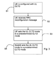
- the following steps can be performed to solve the CLTD mode mismatch between UE and Node which are depicted in Fig. 3 :
- the following steps illustrated in Fig. 4 can be performed whereby the new NodeB can align the Precoding Control Information (PCI) vector used by the UE to the PCI vector used by the new NodeB by transmitting the new PCI vector to the UE:
- PCI Precoding Control Information
- a drawback that can be encountered when transmitting a predetermined PCI-vector from a new serving NodeB is that when the quality of fractional precoding control indication channel (F-PCICH), a channel used to transmit PCI information form the NodeB to a UE, can not be guaranteed it the UE and Node-B still remain in different CLTD configurations (due to decoding errors by the UE).
- F-PCICH fractional precoding control indication channel
- the UE is configured to always set the PCI to a default value, i.e. forget the PCI that it has received from the source Node-B during the serving cell change procedure and use a predetermined precoding vector.
- the pre-coding vector can be fixed and specified in the standard or it can be configurable via signaling, such as RRC signaling.
- the following steps illustrated in Fig. 5 can be performed whereby the new NodeB can align the Precoding Control Information (PCI) vector used by the UE to the PCI vector used by the new NodeB:
- PCI Precoding Control Information
- Using the methods and devices as set out herein can enable the Node-B and the UE to operate with the same CLTD mode even during a handover to a new NodeB. Aside from increasing robustness, and reducing system complexity this will also improve system performance.
Landscapes
- Engineering & Computer Science (AREA)
- Computer Networks & Wireless Communication (AREA)
- Signal Processing (AREA)
- Mobile Radio Communication Systems (AREA)
- Radio Transmission System (AREA)
- Radio Relay Systems (AREA)
Description
- The present invention relates to methods and devices for handling ULTD; in particular Closed loop ULTD, in a cellular radio system.
- Third Generation Partnership Project (3GPP) is currently specifying Closed-loop (CL) Uplink Transmit Diversity feature in Rel-11. Uplink transmit diversity (ULTD) schemes use more than one transmit antenna in the User Equipment (UE) to improve the quality of the uplink transmission. The closed-loop transmit diversity scheme typically requires the receiver to provide fast feedback information about the spatial channel to assist the transmitter in choosing a transmission format over multiple transmit antennas. The approach now considered by the 3GPP is that the network (the serving Node-B or the Node-B in the activate set pointed out by the Radio Network Controller (RNC) in case no serving cell is configured) decides the precoding vector that shall be used by the UE. A precoding vector includes transmission antenna weights for a set of antennas. The antenna weights are associated with a respective transmit antenna, see also 3GPP Technical Specification 25.212 Multiplexing and channel coding, and 3GPP Technical Specification 25.331 Radio Resource Control (RRC).
- There are two UL TD precoding coding schemes 'Beamforming" and "Antenna switching". 3GPP has chosen the 'Beamforming' transmitter scheme for the UL CLTD feature. In beamforming a signal is transmitted from a number of transmit antennas simultaneously with appropriate weighting. Switched antenna diversity implies that one single antenna at a time is used for transmission. In other words switched antenna diversity implies use of a precoding vector with one transmission antenna weight equal to one, and all remaining transmission antenna weights equal to zero.
- There are currently 5 different UL CLTD configuration modes supported by a UE and the NodeB. In the future there may be fewer or more different UL CLTD configuration modes. The switching between these modes can be done by dynamic control via Serving NodeB High Speed - Shared Control Channel (HS-SCCH) orders (in case the UE is configured with a serving NodeB). Note further that the switching between at least some of the modes,
e.g. CLTD configuration 1 and CLTD configuration 5 can be achieved by synchronised configuration via RNC Radio resource Control (RRC) reconfiguration messages.Table 1: UL CLTD configurations U L C L T D Configuration Uplink Channels DPCCH HS-DPCCH E-DPCCH E-DPDCH S- DPCCH 1 Primary Precoding Vector Secondary Precoding Vector 2 Physical Antenna 1Physical Antenna 23 Physical Antenna 2Physical Antenna 14 Physical Antenna 1Deactivate 5 Physical Antenna 2Deactivate - The dynamic activation/de-activation of UL CLTD is important as the transmission from more than two transmit antennas will not be beneficial in certain scenarios and NodeB can take control of the situation via HS-SCCH orders (using local information that the RNC may be unaware of).
- Qualcomm Incorporated: "On the benefits of Uplink Closed Loop Transmit Diversity", 3GPP Draft R1-104737, 17 August 2010, is considered as closest prior art.
- There is a constant desire to improve the performance in cellular radio systems.
- Hence, there exist a need for new methods and devices providing improved performance in cellular radio systems with UEs configurable for UL CTLD.
- It is an object of the present invention to provide improved methods and devices to address the problems as outlined above.
- This object and others are obtained by the methods and devices as set out in the attached claims.
- As has been recognized by the inventors, when a UE is configured with UL CLTD, the Node-B can change the CLTD mode that the UE is operating with by means of HS-SCCH orders. This dynamic switching of the CLTD mode is transparent to the RNC, i.e. the RNC does not know which of the five CLTD modes the UE is configured with when operating in CLTD.
- One approach to address this would be that the UE remembers the CLTD whenever a RRC reconfiguration message from the RNC is received and the
- Old serving cell remains in the active set, and/or
- The new serving cell was in the active set prior to the reconfiguration.
- This would correspond to the approach used for, e.g., dual-cell High Speed Uplink Packet Access (HSUPA).
- As has been recognized by the inventors, if the UE always remembers the CLTD activation status (i.e. CLTD mode in the table above) based on the HS-SCCH orders received from the serving NodeB there would be a problem when the serving Node-B is changed based on the RRC reconfiguration message from RNC. This is because the serving cell change will result in a mismatch between the CLTD modes of the UE and the new serving Node-B is operating with. The new serving NodeB would in this case be forced to always send an HS-SCCH order to the UE to align the CLTD mode of the UE to that of the serving NodeB during serving cell change. Also, the radio channel condition experienced by the UE with the old serving cell and the new serving cell may be very different and remembering the CLTD mode used in the old serving cell may be negative for transmit diversity performance.
- As has further been recognized by the inventors, another problem that can arise is that, if precoded pilot signals are used in CLTD and the precoding weights are not signaled to the NodeB (that is in control of generating PCI commands) in the uplink by the UE, the precoding weights used by the UE would be unknown to the new serving Node-B upon serving cell change.
- For all the reasons specified above there is a need to provide improved configuration methods and devices for UE and Node-B with respect to the UL CLTD activation status (i.e. the CLTD configuration in table 1). This is particularly advantageous when a UE is controlled simultaneously by the HS-SCCH orders and RRC reconfiguration message.
- Thus, in accordance with embodiments described herein methods and devices are described whereby the UE and the Node-B are configured to align the UL CLTD status of the UE and the NodeB during serving cell change involving a new Node-B.
- In accordance with one embodiment, when UL CLTD is configured in UE and the serving Node-B is changed due to a RRC reconfiguration procedure, the UE and the Node-B are configured to use a predetermined CLTD mode. This can typically be one of the five UL CLTD modes currently supported by UE This mode is in accordance with some embodiments set in the standard specification, whereby no signaling is required to determine the predetermined mode.
- In accordance with another embodiment, when UL CLTD is configured in a UE and the serving Node-B is changed due to a RRC reconfiguration procedure, the precoding vector is aligned between UE and network, typically the NodeB.
- In accordance with one embodiment a UE is configured with UL CLTD and the UE receives RRC reconfiguration message that indicates a serving cell change procedure. In response to the RRC reconfiguration, the UE sets the UL CLTD mode to a predetermined UL CLTD mode. The predetermined UL CLTD mode can be set in the standard to a default mode or can be signaled to the UE. The signaling can originate in the RNC and transmitted to the UE via a radio base station.
- In accordance with one embodiment when a UE is configured with UL CLTD. The UE changes serving cell, wherein the new serving cell is associated with a NodeB. The NodeB to which the UE is changing is then set to a predetermined CLTD mode. The predetermined UL CLTD mode can be set in the standard to a default mode or can be signaled to the NodeB.
- In accordance with one embodiment a UE is configured with UL CLTD using precoding with a Precoding Control Information PCI vector The UE receives a RRC reconfiguration message that indicates a serving cell change procedure. In response to the RRC reconfiguration, the UE sets the PCI vector to a predetermined precoding vector. The predetermined precoding vector can be set in the standard to a default vector or can be signaled to the UE.
- In accordance with one embodiment a UE is configured with UL CLTD using precoding with a PCI vector. The UE changes serving cell, wherein the new serving cell is associated with a NodeB. The NodeB to which the UE is changing is set to use a predetermined precoding vector. The predetermined precoding vector can be set in the standard to a default vector or can be signaled to the NodeB.
- The invention also extends to User Equipments (UE) and a radio base stations Node B arranged to perform the above methods. The UE and radio base station Node B can be provided with a controller/controller circuitry for performing the above methods. The controller(s) can be implemented using suitable hardware and or software. The hardware can comprise one or many processors that can be arranged to execute software stored in a readable storage media. The processor(s) can be implemented by a single dedicated processor, by a single shared processor, or by a plurality of individual processors, some of which may be shared or distributed. Moreover, a processor may include, without limitation, digital signal processor (DSP) hardware, ASIC hardware, read only memory (ROM), random access memory (RAM), and/or other storage media.
- The present invention will now be described in more detail by way of non-limiting examples and with reference to the accompanying drawing, in which:
-
Fig. 1 is a view of a cellular radio system, -
Fig. 2 is a view of a transmitter that can be used for transmission precoding -
Fig. 3 is a flow chart depicting different steps performed when aligning ULTD in accordance with one embodiment, -
Fig. 4 is a flowchart depicting different steps performed when aligning PCI vector in accordance with one embodiment, -
Fig. 5 is a flowchart depicting different steps in accordance with an alternative embodiment. - In
Fig. 1 a general view of acellular radio system 100 is depicted. Thesystem 100 depicted inFig 1 is a UTRAN system. However it is also envisaged that the system can be another similar system. Thesystem 100 comprises a number ofbase stations 101, whereof only one is shown for reasons of simplicity. Thebase station 101 can be connected to by user equipments in the figure represented by theUE 103 located in the area served by thebase station 101. TheUE 103 is enabled to transmit using UL CLTD. Further, thebase stations 101 are controlled by a central node such as a Radio Network Controller (RNC) in the case of an UTRAN system. The base station, the central node and the user equipment further comprise controllers/controller circuitry cellular radio system 100 is further configured to support UL CLTD. Thecontrollers - Further,
Fig. 2 illustrates a transmit diversity transmitter that can be used in a UE to obtain precoding in UL CLTD. The exemplary transmitter inFig. 2 uses 2 transmit antennas for transmission other numbers of antennas can of course be used. Thus, a signal to be transmitted S is fed to the two arms of the respective two antennas used. The signal S is multiplied be the respective weights W1 and W2 obtained from the precoding vector and further multiplied by the oscillation frequency. The respective signals are the amplified in respective power amplifiers (PA) and transmitted via the respective antennas (antenna 1 and antenna 2). - Aligning UL CLTD mode during serving cell change:
- When the serving Node-B for a UE is changed based on a RRC reconfiguration message from RNC, this will result in a mismatch with respect to the CLTD modes of the UE and the new serving Node-B is operating with. To resolve this problem, the new serving NodeB is configured to send an HS-SCCH order to the UE to align (i.e. set the CLTD mode to the same for UE and the new serving cell) the CLTD mode of the UE during serving cell change.
- Also, the radio channel condition experienced by the UE with the old serving cell and the new serving cell can be different and remembering the CLTD mode used in the old serving cell can negatively impact transmit diversity performance.
- In accordance with some embodiments the following steps can be performed to solve the CLTD mode mismatch between UE and Node which are depicted in
Fig. 3 : - First in a step S1 a UE is configured with UL CLTD. Next In a step S2 the UE receives RRC reconfiguration message that indicates a serving cell change procedure. Next, in a step S3, the UE sets the UL CLTD mode to a predetermined CLTD mode. Next, in a step S4, the new serving NodeB is also configured to the predetermined CLTD mode. The predetermined CLTD mode can be fixed in the standard. The fixed CLTD mode can typically be any one among the 5 known CLTD modes. In accordance with some embodiments the fixed CLTD mode can be hardcoded in UE and NodeB or signaled to NodeB and UE from the RNC.
- Aligning the PCI vector during serving cell change:
- During the serving cell change involving a new Node-B, it will not be possible for the new serving Node-B to know the precoding vector used by the UE, as the precoding vector was decided by the old serving Node-B.
- In accordance with some embodiments, the following steps illustrated in
Fig. 4 can be performed whereby the new NodeB can align the Precoding Control Information (PCI) vector used by the UE to the PCI vector used by the new NodeB by transmitting the new PCI vector to the UE: - First in a step S11 a UE is configured with UL CLTD. Next, in a step S12 the UE receives a RRC reconfiguration message that indicates a serving cell change procedure. Thereupon, in a step S13, the new serving NodeB transmits a predetermined PCI vector to the UE (i.e. not based on the estimated radio channel between the UE and the new Node-B).
- A drawback that can be encountered when transmitting a predetermined PCI-vector from a new serving NodeB is that when the quality of fractional precoding control indication channel (F-PCICH), a channel used to transmit PCI information form the NodeB to a UE, can not be guaranteed it the UE and Node-B still remain in different CLTD configurations (due to decoding errors by the UE).
- In accordance with an embodiment a method to overcome the drawback above is provided. In accordance with the alternative embodiment the UE is configured to always set the PCI to a default value, i.e. forget the PCI that it has received from the source Node-B during the serving cell change procedure and use a predetermined precoding vector. The pre-coding vector can be fixed and specified in the standard or it can be configurable via signaling, such as RRC signaling.
- Thus, in accordance with some embodiments, the following steps illustrated in
Fig. 5 can be performed whereby the new NodeB can align the Precoding Control Information (PCI) vector used by the UE to the PCI vector used by the new NodeB: - First in a step S21 a UE is configured with UL CLTD. Next, in a step S22 the UE receives a RRC reconfiguration message that indicates a serving cell change procedure. Thereupon, in a step S23, the UE is configured to set the PCI vector to a default value, i.e. forget the PCI that it has received from the source Node-B during the serving cell change procedure and use a predetermined precoding vector. The pre-coding vector can be fixed and specified in the standard or it can be configurable via signaling, such as RRC signaling.
- Using the methods and devices as set out herein can enable the Node-B and the UE to operate with the same CLTD mode even during a handover to a new NodeB. Aside from increasing robustness, and reducing system complexity this will also improve system performance.
Claims (8)
- A method of configuring the Precoding Control Information, PCI, vector in a User Equipment, UE, configured in uplink Closed-loop Transmit Diversity, CLTD, the method comprising the steps of:- receiving (S22) an RRC reconfiguration message that indicates a serving cell change procedure, and- setting (S23) the PCI vector to a default value upon receipt of the RRC reconfiguration message.
- The method according to claim 1, wherein the default value is fixed in the standard.
- The method according to claim 2, wherein the default value is hardcoded in UE.
- The method according to claim 1, wherein the default value is received via radio signaling.
- A User Equipment, UE, (103) adapted to use a Precoding Control information, PCI, vector, the UE being configurable in uplink Closed-loop Transmit Diversity, CLTD, the UE comprising controller circuitry (107) adapted to set the PCI vector to a default value upon receipt of a RRC reconfiguration message that indicates a serving cell change procedure.
- The User Equipment according to claim 5, wherein the default value is fixed in the standard.
- The User Equipment according to claim 6, wherein the default value is hardcoded in UE.
- The User Equipment according to claim 5, wherein the default value Is received via radio signaling.
Applications Claiming Priority (2)
| Application Number | Priority Date | Filing Date | Title |
|---|---|---|---|
| US201161543008P | 2011-10-04 | 2011-10-04 | |
| PCT/SE2012/050943 WO2013051990A2 (en) | 2011-10-04 | 2012-09-06 | Methods and devices for configuring uplink transmission diversity |
Publications (2)
| Publication Number | Publication Date |
|---|---|
| EP2742606A2 EP2742606A2 (en) | 2014-06-18 |
| EP2742606B1 true EP2742606B1 (en) | 2015-01-21 |
Family
ID=47010690
Family Applications (1)
| Application Number | Title | Priority Date | Filing Date |
|---|---|---|---|
| EP12770278.5A Revoked EP2742606B1 (en) | 2011-10-04 | 2012-09-06 | Methods and devices for configuring uplink transmission diversity during a serving cell change |
Country Status (5)
| Country | Link |
|---|---|
| US (3) | US9780861B2 (en) |
| EP (1) | EP2742606B1 (en) |
| ES (1) | ES2532384T3 (en) |
| RU (1) | RU2601428C2 (en) |
| WO (1) | WO2013051990A2 (en) |
Families Citing this family (1)
| Publication number | Priority date | Publication date | Assignee | Title |
|---|---|---|---|---|
| CN103227670B (en) * | 2012-01-30 | 2018-08-24 | 中兴通讯股份有限公司 | Uplink closed loop sends diversity Activiation method and device |
Family Cites Families (14)
| Publication number | Priority date | Publication date | Assignee | Title |
|---|---|---|---|---|
| EP0942615A4 (en) | 1997-08-08 | 2006-03-22 | Mitsubishi Electric Corp | MOBILE COMMUNICATION SYSTEM |
| GB2368240B (en) | 2000-10-20 | 2002-08-28 | Motorola Inc | Method and apparatus for locating a mobile station within a radio communications system |
| GB2431070B (en) | 2005-10-06 | 2008-02-13 | Samsung Electronics Co Ltd | Mobile communications |
| US8660574B2 (en) | 2008-04-02 | 2014-02-25 | Qualcomm Incorporated | Generic positioning protocol |
| TWM378576U (en) | 2008-06-19 | 2010-04-11 | Interdigital Patent Holdings | Multi-cell transmit receive unit |
| US9374749B2 (en) | 2008-11-14 | 2016-06-21 | Qualcomm Incorporated | Methods and systems using same base station carrier handoff for multicarrier support |
| KR20100057473A (en) | 2008-11-21 | 2010-05-31 | 엘지전자 주식회사 | Method of transmitting and receiving carrier configuration information |
| US8982851B2 (en) | 2009-01-06 | 2015-03-17 | Qualcomm Incorporated | Hearability improvements for reference signals |
| US8830918B2 (en) | 2009-03-16 | 2014-09-09 | Interdigital Patent Holdings, Inc. | Method and apparatus for performing uplink transmit diversity |
| EP2424122B1 (en) * | 2009-05-14 | 2015-12-16 | Huawei Technologies Co., Ltd. | Information process method, device and system |
| JP4927123B2 (en) | 2009-06-22 | 2012-05-09 | 株式会社エヌ・ティ・ティ・ドコモ | HANDOVER METHOD, RADIO BASE STATION, AND MOBILE STATION |
| CN102859898A (en) | 2010-01-07 | 2013-01-02 | 交互数字专利控股公司 | Method and apparatus for performing uplink antenna transmit diversity |
| WO2012109529A1 (en) * | 2011-02-11 | 2012-08-16 | Interdigital Patent Holdings, Inc. | Method and apparatus for uplink closed loop transmit diversity transmission initial access |
| US8867502B2 (en) * | 2011-08-15 | 2014-10-21 | Qualcomm Incorporated | Method and apparatus for application of precoder information at the UE in closed loop transmit diversity |
-
2012
- 2012-09-06 EP EP12770278.5A patent/EP2742606B1/en not_active Revoked
- 2012-09-06 WO PCT/SE2012/050943 patent/WO2013051990A2/en not_active Ceased
- 2012-09-06 US US13/640,327 patent/US9780861B2/en active Active
- 2012-09-06 ES ES12770278.5T patent/ES2532384T3/en active Active
- 2012-09-06 RU RU2014117537/07A patent/RU2601428C2/en active
-
2017
- 2017-09-01 US US15/693,937 patent/US10044429B2/en active Active
-
2018
- 2018-07-03 US US16/026,455 patent/US10404349B2/en active Active
Also Published As
| Publication number | Publication date |
|---|---|
| US10044429B2 (en) | 2018-08-07 |
| NZ621681A (en) | 2016-03-31 |
| ES2532384T3 (en) | 2015-03-26 |
| US20170366245A1 (en) | 2017-12-21 |
| EP2742606A2 (en) | 2014-06-18 |
| RU2601428C2 (en) | 2016-11-10 |
| US10404349B2 (en) | 2019-09-03 |
| WO2013051990A2 (en) | 2013-04-11 |
| US20180316408A1 (en) | 2018-11-01 |
| RU2014117537A (en) | 2015-11-10 |
| US9780861B2 (en) | 2017-10-03 |
| US20130083776A1 (en) | 2013-04-04 |
| WO2013051990A3 (en) | 2013-06-20 |
Similar Documents
| Publication | Publication Date | Title |
|---|---|---|
| KR102301580B1 (en) | Signaling in RRC and MAC to PDSCH resource mapping for periodic and quasi-persistent reference signal assumptions | |
| EP4376501A2 (en) | Signaling of full power uplink mimo capability | |
| CN114073022B (en) | CQI saturation mitigation in massive MU-MIMO systems | |
| US20200099432A1 (en) | Methods and Apparatus Relating to Channel State Information Reporting in a Wireless Communication Network | |
| US20210067288A1 (en) | User equipment and wireless communication method | |
| US9504022B2 (en) | Methods and devices for configuring user equipments with multiple transmit antennas | |
| JP2020506572A (en) | Hybrid SRS combination signaling | |
| CN108353409B (en) | Terminal equipment, network equipment, data transmission method and wireless communication system | |
| CN110268637B (en) | User equipment and method for SRS transmission | |
| CN112055371A (en) | Wireless base stations and user equipment | |
| US9520929B2 (en) | Communication control method, user terminal, and base station | |
| JP2020516139A (en) | User equipment and transmission/reception points | |
| KR20250171274A (en) | Multiple CSI reports | |
| US20190149197A1 (en) | Method and device for receiving signal in wireless communication system to which multiple-transmission technique is applied | |
| EP2880775B1 (en) | Providing offset values defining differences between mimo data streams | |
| US10404349B2 (en) | Methods and devices for configuring uplink transmission diversity | |
| EP4356535A1 (en) | Radio network node, and method performed therein | |
| EP3257166B1 (en) | Radio network node, user equipment and methods for handover | |
| NZ621681B2 (en) | Methods and devices for configuring uplink transmission diversity during a serving cell change | |
| CN110268668B (en) | User equipment and wireless communication method | |
| EP2854459A1 (en) | Power control | |
| US20250088865A1 (en) | Beam selection based on power management maximum power reduction (p-mpr) report according to an event from a body proximity sensor (bps) | |
| WO2025171658A1 (en) | Pathloss offset determination in asymmetric heterogeneous networks | |
| WO2025097272A1 (en) | User-equipment-initiated beam switching with low latency |
Legal Events
| Date | Code | Title | Description |
|---|---|---|---|
| PUAI | Public reference made under article 153(3) epc to a published international application that has entered the european phase |
Free format text: ORIGINAL CODE: 0009012 |
|
| 17P | Request for examination filed |
Effective date: 20140204 |
|
| AK | Designated contracting states |
Kind code of ref document: A2 Designated state(s): AL AT BE BG CH CY CZ DE DK EE ES FI FR GB GR HR HU IE IS IT LI LT LU LV MC MK MT NL NO PL PT RO RS SE SI SK SM TR |
|
| RIN1 | Information on inventor provided before grant (corrected) |
Inventor name: HULTELL, JOHAN Inventor name: SILVERIS, PAULSON ANGELO VIJAY |
|
| RIN1 | Information on inventor provided before grant (corrected) |
Inventor name: SILVERIS, PAULSON ANGELO VIJAY Inventor name: HULTELL, JOHAN |
|
| GRAP | Despatch of communication of intention to grant a patent |
Free format text: ORIGINAL CODE: EPIDOSNIGR1 |
|
| DAX | Request for extension of the european patent (deleted) | ||
| INTG | Intention to grant announced |
Effective date: 20140919 |
|
| GRAS | Grant fee paid |
Free format text: ORIGINAL CODE: EPIDOSNIGR3 |
|
| GRAA | (expected) grant |
Free format text: ORIGINAL CODE: 0009210 |
|
| AK | Designated contracting states |
Kind code of ref document: B1 Designated state(s): AL AT BE BG CH CY CZ DE DK EE ES FI FR GB GR HR HU IE IS IT LI LT LU LV MC MK MT NL NO PL PT RO RS SE SI SK SM TR |
|
| REG | Reference to a national code |
Ref country code: GB Ref legal event code: FG4D |
|
| REG | Reference to a national code |
Ref country code: CH Ref legal event code: EP |
|
| REG | Reference to a national code |
Ref country code: IE Ref legal event code: FG4D |
|
| REG | Reference to a national code |
Ref country code: DE Ref legal event code: R096 Ref document number: 602012005094 Country of ref document: DE Effective date: 20150305 |
|
| REG | Reference to a national code |
Ref country code: AT Ref legal event code: REF Ref document number: 709564 Country of ref document: AT Kind code of ref document: T Effective date: 20150315 |
|
| REG | Reference to a national code |
Ref country code: ES Ref legal event code: FG2A Ref document number: 2532384 Country of ref document: ES Kind code of ref document: T3 Effective date: 20150326 |
|
| REG | Reference to a national code |
Ref country code: NL Ref legal event code: T3 |
|
| REG | Reference to a national code |
Ref country code: AT Ref legal event code: MK05 Ref document number: 709564 Country of ref document: AT Kind code of ref document: T Effective date: 20150121 |
|
| REG | Reference to a national code |
Ref country code: LT Ref legal event code: MG4D |
|
| PG25 | Lapsed in a contracting state [announced via postgrant information from national office to epo] |
Ref country code: NO Free format text: LAPSE BECAUSE OF FAILURE TO SUBMIT A TRANSLATION OF THE DESCRIPTION OR TO PAY THE FEE WITHIN THE PRESCRIBED TIME-LIMIT Effective date: 20150421 Ref country code: FI Free format text: LAPSE BECAUSE OF FAILURE TO SUBMIT A TRANSLATION OF THE DESCRIPTION OR TO PAY THE FEE WITHIN THE PRESCRIBED TIME-LIMIT Effective date: 20150121 Ref country code: SE Free format text: LAPSE BECAUSE OF FAILURE TO SUBMIT A TRANSLATION OF THE DESCRIPTION OR TO PAY THE FEE WITHIN THE PRESCRIBED TIME-LIMIT Effective date: 20150121 Ref country code: HR Free format text: LAPSE BECAUSE OF FAILURE TO SUBMIT A TRANSLATION OF THE DESCRIPTION OR TO PAY THE FEE WITHIN THE PRESCRIBED TIME-LIMIT Effective date: 20150121 Ref country code: BG Free format text: LAPSE BECAUSE OF FAILURE TO SUBMIT A TRANSLATION OF THE DESCRIPTION OR TO PAY THE FEE WITHIN THE PRESCRIBED TIME-LIMIT Effective date: 20150421 Ref country code: LT Free format text: LAPSE BECAUSE OF FAILURE TO SUBMIT A TRANSLATION OF THE DESCRIPTION OR TO PAY THE FEE WITHIN THE PRESCRIBED TIME-LIMIT Effective date: 20150121 |
|
| PG25 | Lapsed in a contracting state [announced via postgrant information from national office to epo] |
Ref country code: RS Free format text: LAPSE BECAUSE OF FAILURE TO SUBMIT A TRANSLATION OF THE DESCRIPTION OR TO PAY THE FEE WITHIN THE PRESCRIBED TIME-LIMIT Effective date: 20150121 Ref country code: LV Free format text: LAPSE BECAUSE OF FAILURE TO SUBMIT A TRANSLATION OF THE DESCRIPTION OR TO PAY THE FEE WITHIN THE PRESCRIBED TIME-LIMIT Effective date: 20150121 Ref country code: PL Free format text: LAPSE BECAUSE OF FAILURE TO SUBMIT A TRANSLATION OF THE DESCRIPTION OR TO PAY THE FEE WITHIN THE PRESCRIBED TIME-LIMIT Effective date: 20150121 Ref country code: IS Free format text: LAPSE BECAUSE OF FAILURE TO SUBMIT A TRANSLATION OF THE DESCRIPTION OR TO PAY THE FEE WITHIN THE PRESCRIBED TIME-LIMIT Effective date: 20150521 Ref country code: AT Free format text: LAPSE BECAUSE OF FAILURE TO SUBMIT A TRANSLATION OF THE DESCRIPTION OR TO PAY THE FEE WITHIN THE PRESCRIBED TIME-LIMIT Effective date: 20150121 Ref country code: GR Free format text: LAPSE BECAUSE OF FAILURE TO SUBMIT A TRANSLATION OF THE DESCRIPTION OR TO PAY THE FEE WITHIN THE PRESCRIBED TIME-LIMIT Effective date: 20150422 |
|
| REG | Reference to a national code |
Ref country code: FR Ref legal event code: PLFP Year of fee payment: 4 |
|
| REG | Reference to a national code |
Ref country code: DE Ref legal event code: R026 Ref document number: 602012005094 Country of ref document: DE |
|
| PLBI | Opposition filed |
Free format text: ORIGINAL CODE: 0009260 |
|
| PG25 | Lapsed in a contracting state [announced via postgrant information from national office to epo] |
Ref country code: SK Free format text: LAPSE BECAUSE OF FAILURE TO SUBMIT A TRANSLATION OF THE DESCRIPTION OR TO PAY THE FEE WITHIN THE PRESCRIBED TIME-LIMIT Effective date: 20150121 Ref country code: CZ Free format text: LAPSE BECAUSE OF FAILURE TO SUBMIT A TRANSLATION OF THE DESCRIPTION OR TO PAY THE FEE WITHIN THE PRESCRIBED TIME-LIMIT Effective date: 20150121 Ref country code: RO Free format text: LAPSE BECAUSE OF FAILURE TO SUBMIT A TRANSLATION OF THE DESCRIPTION OR TO PAY THE FEE WITHIN THE PRESCRIBED TIME-LIMIT Effective date: 20150121 Ref country code: EE Free format text: LAPSE BECAUSE OF FAILURE TO SUBMIT A TRANSLATION OF THE DESCRIPTION OR TO PAY THE FEE WITHIN THE PRESCRIBED TIME-LIMIT Effective date: 20150121 Ref country code: DK Free format text: LAPSE BECAUSE OF FAILURE TO SUBMIT A TRANSLATION OF THE DESCRIPTION OR TO PAY THE FEE WITHIN THE PRESCRIBED TIME-LIMIT Effective date: 20150121 |
|
| 26 | Opposition filed |
Opponent name: SONY CORPORATION Effective date: 20151021 |
|
| PLAX | Notice of opposition and request to file observation + time limit sent |
Free format text: ORIGINAL CODE: EPIDOSNOBS2 |
|
| PG25 | Lapsed in a contracting state [announced via postgrant information from national office to epo] |
Ref country code: IT Free format text: LAPSE BECAUSE OF FAILURE TO SUBMIT A TRANSLATION OF THE DESCRIPTION OR TO PAY THE FEE WITHIN THE PRESCRIBED TIME-LIMIT Effective date: 20150121 |
|
| PG25 | Lapsed in a contracting state [announced via postgrant information from national office to epo] |
Ref country code: SI Free format text: LAPSE BECAUSE OF FAILURE TO SUBMIT A TRANSLATION OF THE DESCRIPTION OR TO PAY THE FEE WITHIN THE PRESCRIBED TIME-LIMIT Effective date: 20150121 |
|
| PLBB | Reply of patent proprietor to notice(s) of opposition received |
Free format text: ORIGINAL CODE: EPIDOSNOBS3 |
|
| PG25 | Lapsed in a contracting state [announced via postgrant information from national office to epo] |
Ref country code: LU Free format text: LAPSE BECAUSE OF FAILURE TO SUBMIT A TRANSLATION OF THE DESCRIPTION OR TO PAY THE FEE WITHIN THE PRESCRIBED TIME-LIMIT Effective date: 20150906 Ref country code: MC Free format text: LAPSE BECAUSE OF FAILURE TO SUBMIT A TRANSLATION OF THE DESCRIPTION OR TO PAY THE FEE WITHIN THE PRESCRIBED TIME-LIMIT Effective date: 20150121 |
|
| REG | Reference to a national code |
Ref country code: CH Ref legal event code: PL |
|
| REG | Reference to a national code |
Ref country code: IE Ref legal event code: MM4A |
|
| PG25 | Lapsed in a contracting state [announced via postgrant information from national office to epo] |
Ref country code: CH Free format text: LAPSE BECAUSE OF NON-PAYMENT OF DUE FEES Effective date: 20150930 Ref country code: LI Free format text: LAPSE BECAUSE OF NON-PAYMENT OF DUE FEES Effective date: 20150930 Ref country code: IE Free format text: LAPSE BECAUSE OF NON-PAYMENT OF DUE FEES Effective date: 20150906 |
|
| REG | Reference to a national code |
Ref country code: FR Ref legal event code: PLFP Year of fee payment: 5 |
|
| PG25 | Lapsed in a contracting state [announced via postgrant information from national office to epo] |
Ref country code: MT Free format text: LAPSE BECAUSE OF FAILURE TO SUBMIT A TRANSLATION OF THE DESCRIPTION OR TO PAY THE FEE WITHIN THE PRESCRIBED TIME-LIMIT Effective date: 20150121 |
|
| PG25 | Lapsed in a contracting state [announced via postgrant information from national office to epo] |
Ref country code: SM Free format text: LAPSE BECAUSE OF FAILURE TO SUBMIT A TRANSLATION OF THE DESCRIPTION OR TO PAY THE FEE WITHIN THE PRESCRIBED TIME-LIMIT Effective date: 20150121 Ref country code: HU Free format text: LAPSE BECAUSE OF FAILURE TO SUBMIT A TRANSLATION OF THE DESCRIPTION OR TO PAY THE FEE WITHIN THE PRESCRIBED TIME-LIMIT; INVALID AB INITIO Effective date: 20120906 |
|
| PG25 | Lapsed in a contracting state [announced via postgrant information from national office to epo] |
Ref country code: CY Free format text: LAPSE BECAUSE OF FAILURE TO SUBMIT A TRANSLATION OF THE DESCRIPTION OR TO PAY THE FEE WITHIN THE PRESCRIBED TIME-LIMIT Effective date: 20150121 |
|
| RDAF | Communication despatched that patent is revoked |
Free format text: ORIGINAL CODE: EPIDOSNREV1 |
|
| STAA | Information on the status of an ep patent application or granted ep patent |
Free format text: STATUS: THE PATENT HAS BEEN GRANTED |
|
| APAH | Appeal reference modified |
Free format text: ORIGINAL CODE: EPIDOSCREFNO |
|
| APBM | Appeal reference recorded |
Free format text: ORIGINAL CODE: EPIDOSNREFNO |
|
| APBP | Date of receipt of notice of appeal recorded |
Free format text: ORIGINAL CODE: EPIDOSNNOA2O |
|
| REG | Reference to a national code |
Ref country code: FR Ref legal event code: PLFP Year of fee payment: 6 |
|
| APBQ | Date of receipt of statement of grounds of appeal recorded |
Free format text: ORIGINAL CODE: EPIDOSNNOA3O |
|
| PG25 | Lapsed in a contracting state [announced via postgrant information from national office to epo] |
Ref country code: TR Free format text: LAPSE BECAUSE OF FAILURE TO SUBMIT A TRANSLATION OF THE DESCRIPTION OR TO PAY THE FEE WITHIN THE PRESCRIBED TIME-LIMIT Effective date: 20150121 Ref country code: MK Free format text: LAPSE BECAUSE OF FAILURE TO SUBMIT A TRANSLATION OF THE DESCRIPTION OR TO PAY THE FEE WITHIN THE PRESCRIBED TIME-LIMIT Effective date: 20150121 Ref country code: PT Free format text: LAPSE BECAUSE OF FAILURE TO SUBMIT A TRANSLATION OF THE DESCRIPTION OR TO PAY THE FEE WITHIN THE PRESCRIBED TIME-LIMIT Effective date: 20150121 |
|
| REG | Reference to a national code |
Ref country code: FR Ref legal event code: PLFP Year of fee payment: 7 |
|
| PG25 | Lapsed in a contracting state [announced via postgrant information from national office to epo] |
Ref country code: AL Free format text: LAPSE BECAUSE OF FAILURE TO SUBMIT A TRANSLATION OF THE DESCRIPTION OR TO PAY THE FEE WITHIN THE PRESCRIBED TIME-LIMIT Effective date: 20150121 |
|
| PLAB | Opposition data, opponent's data or that of the opponent's representative modified |
Free format text: ORIGINAL CODE: 0009299OPPO |
|
| R26 | Opposition filed (corrected) |
Opponent name: SONY GROUP CORPORATION Effective date: 20151021 |
|
| PGFP | Annual fee paid to national office [announced via postgrant information from national office to epo] |
Ref country code: NL Payment date: 20210926 Year of fee payment: 10 Ref country code: FR Payment date: 20210927 Year of fee payment: 10 |
|
| PGFP | Annual fee paid to national office [announced via postgrant information from national office to epo] |
Ref country code: GB Payment date: 20210927 Year of fee payment: 10 Ref country code: BE Payment date: 20210927 Year of fee payment: 10 Ref country code: DE Payment date: 20210929 Year of fee payment: 10 |
|
| PGFP | Annual fee paid to national office [announced via postgrant information from national office to epo] |
Ref country code: ES Payment date: 20211001 Year of fee payment: 10 |
|
| REG | Reference to a national code |
Ref country code: DE Ref legal event code: R103 Ref document number: 602012005094 Country of ref document: DE Ref country code: DE Ref legal event code: R064 Ref document number: 602012005094 Country of ref document: DE |
|
| APBU | Appeal procedure closed |
Free format text: ORIGINAL CODE: EPIDOSNNOA9O |
|
| RDAG | Patent revoked |
Free format text: ORIGINAL CODE: 0009271 |
|
| STAA | Information on the status of an ep patent application or granted ep patent |
Free format text: STATUS: PATENT REVOKED |
|
| REG | Reference to a national code |
Ref country code: FI Ref legal event code: MGE |
|
| 27W | Patent revoked |
Effective date: 20220602 |
|
| GBPR | Gb: patent revoked under art. 102 of the ep convention designating the uk as contracting state |
Effective date: 20220602 |