EP2741993B1 - Test method of an elevator system and a monitoring device for performing the test method - Google Patents
Test method of an elevator system and a monitoring device for performing the test method Download PDFInfo
- Publication number
- EP2741993B1 EP2741993B1 EP12740940.7A EP12740940A EP2741993B1 EP 2741993 B1 EP2741993 B1 EP 2741993B1 EP 12740940 A EP12740940 A EP 12740940A EP 2741993 B1 EP2741993 B1 EP 2741993B1
- Authority
- EP
- European Patent Office
- Prior art keywords
- microprocessor
- signal
- control unit
- value
- bus node
- Prior art date
- Legal status (The legal status is an assumption and is not a legal conclusion. Google has not performed a legal analysis and makes no representation as to the accuracy of the status listed.)
- Active
Links
- 238000010998 test method Methods 0.000 title claims description 25
- 238000012806 monitoring device Methods 0.000 title claims description 24
- 238000009434 installation Methods 0.000 claims description 9
- 238000012795 verification Methods 0.000 claims description 2
- 230000004044 response Effects 0.000 description 24
- 238000012360 testing method Methods 0.000 description 21
- 230000005540 biological transmission Effects 0.000 description 4
- 230000006698 induction Effects 0.000 description 4
- 230000002269 spontaneous effect Effects 0.000 description 4
- 238000006243 chemical reaction Methods 0.000 description 3
- 238000004891 communication Methods 0.000 description 2
- 239000004020 conductor Substances 0.000 description 2
- 238000012423 maintenance Methods 0.000 description 2
- 238000005259 measurement Methods 0.000 description 2
- 230000004913 activation Effects 0.000 description 1
- 230000006399 behavior Effects 0.000 description 1
- 239000002131 composite material Substances 0.000 description 1
- 230000001419 dependent effect Effects 0.000 description 1
- 230000000694 effects Effects 0.000 description 1
- 230000002349 favourable effect Effects 0.000 description 1
- 238000000034 method Methods 0.000 description 1
- 230000009154 spontaneous behavior Effects 0.000 description 1
Images

Classifications
-
- B—PERFORMING OPERATIONS; TRANSPORTING
- B66—HOISTING; LIFTING; HAULING
- B66B—ELEVATORS; ESCALATORS OR MOVING WALKWAYS
- B66B5/00—Applications of checking, fault-correcting, or safety devices in elevators
- B66B5/0006—Monitoring devices or performance analysers
-
- B—PERFORMING OPERATIONS; TRANSPORTING
- B66—HOISTING; LIFTING; HAULING
- B66B—ELEVATORS; ESCALATORS OR MOVING WALKWAYS
- B66B13/00—Doors, gates, or other apparatus controlling access to, or exit from, cages or lift well landings
- B66B13/22—Operation of door or gate contacts
-
- B—PERFORMING OPERATIONS; TRANSPORTING
- B66—HOISTING; LIFTING; HAULING
- B66B—ELEVATORS; ESCALATORS OR MOVING WALKWAYS
- B66B5/00—Applications of checking, fault-correcting, or safety devices in elevators
- B66B5/0006—Monitoring devices or performance analysers
- B66B5/0018—Devices monitoring the operating condition of the elevator system
- B66B5/0031—Devices monitoring the operating condition of the elevator system for safety reasons
Definitions
- the invention relates to a test method of an elevator installation and to a monitoring device for carrying out the test method according to the subject matter of the independent claims.
- Conventional elevator systems have safety circuits consisting of series-connected safety elements.
- these security elements monitor the condition of manhole or cabin doors.
- Such a security element can be a contact.
- An open contact shows that e.g. a door is open and a potentially inadmissible door condition has occurred. If an inadmissible open state of the doors is now identified when the contact is open, the safety circuit is interrupted. This has the consequence that a drive or brakes, which act on the travel of an elevator car, bring the elevator car to a standstill.
- a monitoring device for an elevator system which has a control unit and at least one bus node and a bus.
- the bus allows communication between the bus node and the control unit.
- the bus node monitors the state of shaft doors by means of a security element.
- the bus node has a first microprocessor and a second microprocessor.
- the first microprocessor is designed so that it reads digital presetting signals from the control unit, converts them into an analog signal and acts on the security element.
- the second microprocessor in turn measures the analog signal after the security element and converts it into a digital signal.
- the second microprocessor provides this digital information to the control unit.
- This information is either sent from the bus nodes as digital signals to the control unit or is requested by the control unit by means of a query. If the safety switch is open and the second microprocessor in the sequence does not measure an analog signal, it spontaneously sends a negative status information to the control unit.
- a default signal test is proposed.
- the control unit sends different digital default signals to the first microprocessor.
- the control unit may determine, based on the digital signals provided or transmitted by the second microprocessor, whether the two microprocessors are properly translating the varying default signals.
- a default signal with the value zero or an error value represents a special case in which the spontaneous response of the second microprocessor is provoked.
- the control unit sends the first microprocessor a digital default signal with error value, which converts this into an analog command signal with error value and thus acts on the security element. This simulates an open security element.
- the controller expects the second microprocessor to respond spontaneously due to the detected analog default signal and send a digital signal to the controller. If this expectation of the control unit is met and the other default signals are properly implemented, the controller may assume that both the first and the second microprocessor are functioning properly.
- testable bus nodes lies in their still relatively expensive production. In the mass production of these bus nodes even small cost savings have a big price effect.
- the object of the present invention is thus to provide a test method of an elevator installation or a monitoring device for carrying out the test method, which allow a favorable production of the monitoring device, in particular the bus node.
- the object is achieved by a test method and a monitoring device according to the independent claims.
- a first aspect relates to a monitoring device of an elevator installation with a control unit and at least one bus node.
- the bus node has a first microprocessor and a second microprocessor.
- the control unit and the bus node communicate via a bus.
- the monitoring device is characterized in that the first microprocessor and the second microprocessor are connected without interruption via a signal line.
- an interruption-free signal line is to be understood here a signal line comprising a continuous conductor, which connects as here, for example, two microprocessors directly to each other.
- a signal line which is made of a plurality of composite sub-elements that are in contact is not regarded as a continuous conductor or signal line without interruption.
- a signal without interruption thus comprises no sub-elements such as switches, security elements or the like, even if they are in contact with the signal line or parts thereof.
- the monitoring device is part of a test procedure.
- the method comprises the following steps: the control unit transmits a default signal to the first microprocessor, the first microprocessor transmits the signal to the second microprocessor via the signal line, and the second microprocessor provides the signal to the control unit. Finally, the control unit verifies that the signal provided corresponds to a signal expected by the control unit.
- the advantage of this monitoring device is that in the test procedure, the setpoint signal sent by the control unit and then converted in the first microprocessor is sent by the first microprocessor to the second microprocessor via a signal line. Because this signal line connects the first microprocessor and the second microprocessor without interruption, so that the signal line connects the first microprocessor and the second microprocessor directly.
- Particularly advantageous is the bus node internal arrangement of the signal line. Since this signal line contains no additional elements such as a security element or a switch and can be made very short, their resistance is very small. Signals can thus be sent with very little energy from the first to the second microprocessor. Accordingly, in comparison to the bus node described above, a signal amplifier of low efficiency can be used. The bus node is therefore particularly inexpensive to produce.
- the control unit sends a default signal with a first value to a bus node.
- the bus node provides a signal with a second value.
- the control unit verifies that the second provided value is assignable to the first transmitted value.
- the second value is then assignable to the first value if the second provided value corresponds to a second value expected by the controller in response to the first value. If the second provided value is assignable then the test is passed. If the second provided value is not assignable to the first value, then the test is failed.
- the first microprocessor of the bus node reads the default signal sent by the control unit with the first value and converts this default signal into a bus node-internal signal that the first microprocessor transmits to the second microprocessor via the signal line.
- the second microprocessor reads this signal, converts it into a response signal of a second value and provides the response signal to the control unit.
- the default signal represents a first digital current value.
- the first microprocessor reads this current value and converts it into an analog current signal having a current that corresponds to the first digital current value of the default signal.
- the first microprocessor supplies the signal line with the analog current signal.
- the second microprocessor measures the current of the analog current signal and converts the measured current into a second current digital signal corresponding to the measured current value.
- This digital signal provides the second microprocessor of the control unit as a response signal.
- the control unit verifies whether the second current value can be assigned to or corresponds to the first transmitted current value.
- the first microprocessor applies an analog signal to the signal line comprising one of these values.
- the first microprocessor loads the signal line with a digital signal having a code value which preferably corresponds to a code value of the default signal.
- This code value is read by the second microprocessor and provided according to the control unit. The conversion of the digital signal into an analogue one Signal and back to a digital signal in the first and second microprocessor is omitted here.
- the code value may represent any number or sequence of numbers
- At least two queries are performed with two different default values. If the value of the provided response signal is twice assignable to the two different values of the default signals, the test is passed.
- control unit performs the test procedure of the bus node at recurring time intervals.
- the time interval depends on the reliability of the first and second microprocessors used and is between 1 and 100 s.
- the control unit sends a default signal containing an error value to a bus node.
- a signal provided by a security element to the second microprocessor simulating an unsafe condition of the elevator system is simulated.
- the control unit expects that the tested bus node spontaneously transmits a response signal to the control unit.
- a current zero, voltage zero, frequency zero, or zero duty cycle correspond to such an error value.
- an open security element which is designed as a safety switch is simulated.
- a code value may represent an unsafe condition of the elevator system or an error value.
- the control unit sends a default signal with an error value to the first microprocessor. This reads in the value and supplies the bus node-internal signal line with a signal which has an error value.
- the second microprocessor reads this signal with the error value and spontaneously transmits a response signal to the control unit. Again, the transmitted from the first microprocessor via the signal line signal is an analog or a digital signal.
- the present monitoring device 10 and the present test method are particularly suitable for use in elevator installations.
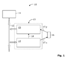
- Fig. 1 shows a first embodiment of the monitoring device 10.
- the monitoring device 10 has a control unit 11 and at least one bus node 13. The communication between the control unit 11 and the bus node 13 via a bus 12. Thus, between the bus node 13 and the control unit 11 data be sent in both directions over the bus.
- the bus node 13 itself comprises a first microprocessor 14 and a second microprocessor 15.
- the first microprocessor 14 and the second microprocessor 15 are each designed so that the former receives default signals from the control unit 11 and the latter provides status information as response signals of the control unit 11.
- the bus node 13 is also connected via a bus node external signal line 17.1, 17.2 with a security element 16, wherein a first part 17.1 of the bus node external signal line connects the first microprocessor 14 with the security element 16 and a second part 17.2 of the bus node external signal line the security element 16 to the second microprocessor 15 connects. Finally, the first microprocessor 14 and the second microprocessor 15 are connected to each other without interruption via a bus node-internal signal line 18.
- the control unit 11, the bus 12 and the at least one bus node 13 form a bus system. Within this bus system each bus node 13 has its own, unique address. This message is used to establish the message between the controller 11 and a bus node 13.
- the control unit 11 is via the bus 12 digital default signals to the first microprocessor 14.
- the control unit addresses a specific bus node 13 and tells the first microprocessor 14, the default signal.
- the first microprocessor 14 receives this default signal and generates the default signal according to an analog signal which is applied to the bus node external signal line 17.1, 17.2.
- the analog signal may be a certain voltage, current, frequency or duty value.
- the security element 16 shows the state of a security-relevant element.
- the security element 16 finds e.g. as door contact, latch contact, buffer contact, flap contact, travel switch or emergency stop switch application.
- the safety element 16 is designed, for example, such that a closed safety element 16 represents a safe state and an open safety element 16 represents a potentially dangerous state of an elevator installation.
- the second microprocessor 15 measures behind the security element 16 the incoming analog signal via the bus node-external signal line 17.2. After the measurement, the second microprocessor 15 converts the measured analog signal into a digital signal. The second microprocessor 15 finally provides the digital signal to the control unit 11.
- the security element 16 monitors, for example, the state of a car or a shaft door. When an open state of one of these doors, the security element 16 is also open, indicating a potentially dangerous condition of the elevator system. In this case, the bus node-external signal line 17.1, 17.2 is interrupted. As described above, the second microprocessor 15 measures the analog signal arriving behind the security element 16. With an open security element 16, this analog signal from the second microprocessor 15 is no longer measurable. The second microprocessor 15 in this case measures an analog signal having a zero value of error.
- the control unit 11 is able to locate the error accurately. If necessary, the control unit 11 takes measures to remedy the error or to convert the elevator into a safe operating mode. These operating modes include i.a. the maintenance of a residual availability of the elevator in a safe driving area of the elevator car, the evacuation of trapped passengers, an emergency stop or finally the alerting of maintenance and service personnel to free trapped passengers and / or to eliminate an error that can not be remedied by the control unit.
- the safe operation of a bus node 13 depends primarily on the functionality of the first microprocessor 14 and the second microprocessor 15. In particular, it must be ensured that the following steps are performed without error by the first and second microprocessors 14, 15: conversion of the default signal into an analog signal in the first microprocessor 14, measurement of the analog signal in the second microprocessor 15, provision of the response signal by the second microprocessor 15 and the spontaneous behavior of the second microprocessor 15 when measuring an analog signal with an error value.
- the functional behavior of a bus node 13 is checked during the conversion of a default signal in normal operation.
- the control unit 11 sends a default signal with a current, voltage, frequency or duty value in digital form to a selected bus node 13 by specifying the address of the bus node 13.
- This default signal is renewed at certain time intervals, ie, the control unit 11 sends the bus node 13 a default signal with a new current, voltage, frequency or duty cycle.
- the new value is different from the previous value.
- the first microprocessor 14 generates a corresponding analog signal according to the default signal.
- the first microprocessor 14 supplies the bus node-internal signal line 18 with this analog signal.
- the second microprocessor 15 measures this analog signal and provides the measured value as a digital response signal.
- the control unit 11 addresses the second microprocessor 15 of the bus node 13 and provides the data of the provided as a digital response signal via a read function Current, voltage, frequency or duty cycle value.
- time intervals between such default polling cycles are basically freely adjustable and depend primarily on the reliability of the bus node components. Preferably, these time intervals last several seconds. With high reliability, you can also set time intervals of 100s or longer.
- the control unit 11 performs this test procedure with all the bus nodes 13 in turn and checks their resonance. That the digital command signals and the digital response signals provided by the respective second microprocessors 15 are verified by the control unit 11. If the default signals are associable with the provided digital response signals, the controller 11 recognizes that the first microprocessor 14 and the second microprocessor 15 are functioning properly in the implementation of a default signal in normal operation.
- an opened security element 16 is simulated.
- the control unit 11 simulates the opened security element 16 in that a default signal with an error value of 0 mA, 0 mV, 0 Hz or 0% is given to a specific bus node 13.
- This digital default signal with error value is converted by the first microprocessor 14 into an analog signal with error value.
- the analog signal from the first microprocessor 14 of the bus node internal signal line 18 is applied.
- the second microprocessor 15 measures this analog signal and spontaneously logs on to the control unit 11 in the case of perfect functioning. This test guarantees, with a positive output, that each opening of a security element 16 leads to a spontaneous transmission of a digital response signal of the bus node 13 to the control unit 11.
- This second test is performed in a time-recurring manner for each bus node 13.
- the test time is largely dependent on the speed of data transmission via the bus 12 and is usually 50 to 100 ms.
- the frequency of the zero-preset test depends primarily on the reliability of the second microprocessor 15 used. The more reliable the second microprocessor 15, the less frequently it must be tested in order to ensure safe operation of the elevator.
- the default test with error value is performed at least once a day. This test can also be repeated in the order of minutes or hours.
- Fig. 2 shows a second embodiment of the monitoring device 10.
- This monitoring device 10 also includes a control unit 11, at least one bus node 13 and a bus 12, which connects the control unit 11 with a bus node 13.
- the bus node 13 has according to the first embodiment Fig. 1 via a first microprocessor 14 and a second microprocessor 15, which are connected to each other without interruption via a bus node-internal signal line 18.
- a non-contact security element 16.1, 16.2 is connected via a bus node-external signal line 17 to the second microprocessor 15.
- the non-contact security element 16.1, 16.2 here comprises, for example, an RFID tag 16.2 and an RFID reading unit 16.1.
- the RFID tag 16.2 and the RFID reading unit 16.1 each have an induction coil.
- the RFID reading unit side induction coil is supplied with electrical energy and stimulates falls below a certain distance to the RFID tag side induction coil.
- the RFID tag 16.2 transmits a digital code value via the two induction coils to the RFID reading unit 16.1.
- the RFID reading unit 16.1 reads in this digital code value and converts this code value into an analog signal having the same code value. Accordingly, the RFID reading unit 16.1 loads the bus node-external signal line 17 with the analog signal.
- the second microprocessor 15 measures this analog signal and converts it into a digital response signal having the code value and provides it to the control unit 11.
- the non-contact security element 16.1, 16.2 monitors, for example, the state of a car or shaft door. As long as such a door is closed, the distance between the RFID tag 16.2 and the RFID reading unit 16.1 remains sufficiently small to allow transmission of the digital code value. Accordingly, the second microprocessor 15 provides a digital signal with the read-out code value of the RFID tag 16.2 of the control unit 11. With an open door, which represents a potential unsafe condition of the elevator installation, by contrast, the transmission of the code value to the RFID reading unit 16.1 is interrupted. The RFID reading unit 16.1 reads So no code value or an error value. Accordingly, the second microprocessor 15 also measures a signal with an error value. In this situation, the second microprocessor 15 spontaneously transmits a digital signal to the control unit 11.
- the reliable operation of a bus node 13 is checked by means of two tests.
- the control unit 11 sends a digital preset signal having a first code value to the first microprocessor 14.
- the first microprocessor 14 converts the default signal into an analog signal having the code value and drives the bus node internal signal line 18.
- the second microprocessor 15 measures this analog Signal and converts it into a digital response signal with the measured code value.
- the second microprocessor 15 provides the digital response signal to the control unit 11.
- the control unit 11 verifies whether the code value of the response signal corresponds to the code value of the default signal. If the code value of the response signal can be assigned to the code value of the default signal, then the test is passed. Preferably, the code value of the default signal deviates from the code value of the RFID tag 16.2.
- a second test relates to simulating an error value and the corresponding spontaneous response of the second microprocessor 15.
- the control unit 11 sends a digital command signal having an error value to the first microprocessor 14.
- the first microprocessor 14 converts this command signal into an analog signal having the error value and acts on the bus node internal signal line 18 with this analog signal.
- the second microprocessor 15 measures the analog signal with the error value and spontaneously transmits a digital response signal to the control unit 11.
- the second test is completed positively when the control unit 11 verifies the expected spontaneous response of the second microprocessor 15.
- the time intervals in which the control unit 11 transmits default signals to a bus node 13 for test purposes are correspondingly adjustable in the first embodiment of the monitoring device 10.
- the two test methods of the second embodiment of the monitoring device 10 are also performed by the control unit 11 for each bus node 13.
- the bus node-internal signal line 18 in each of the two embodiments of the monitoring device 10 is supplied with a digital signal which corresponds to the different values of the default signal.
Description
Die Erfindung betrifft ein Testverfahren einer Aufzugsanlage und eine Überwachungseinrichtung zum Durchführen des Testverfahrens gemäss dem Gegenstand der unabhängigen Ansprüche.The invention relates to a test method of an elevator installation and to a monitoring device for carrying out the test method according to the subject matter of the independent claims.
Herkömmliche Aufzugsanlagen weisen Sicherheitskreise auf, die aus in Serie geschalteten Sicherheitselementen bestehen. Diese Sicherheitselemente überwachen zum Beispiel den Zustand von Schacht- oder Kabinentüren. Ein solches Sicherheitselement kann ein Kontakt sein. Ein offener Kontakt zeigt, dass z.B. eine Türe offen steht und ein potentiell unzulässiger Türzustand aufgetreten ist. Wird nun bei geöffnetem Kontakt ein unzulässiger offener Zustand der Türen identifiziert, so wird der Sicherheitskreis unterbrochen. Dies hat zur Folge, dass ein Antrieb oder Bremsen, die auf die Fahrt einer Aufzugskabine einwirken, die Aufzugskabine zum Stillstand bringen.Conventional elevator systems have safety circuits consisting of series-connected safety elements. For example, these security elements monitor the condition of manhole or cabin doors. Such a security element can be a contact. An open contact shows that e.g. a door is open and a potentially inadmissible door condition has occurred. If an inadmissible open state of the doors is now identified when the contact is open, the safety circuit is interrupted. This has the consequence that a drive or brakes, which act on the travel of an elevator car, bring the elevator car to a standstill.
Aus der Patentschrift
Damit ein sicherer Betrieb der Aufzugsanlage gewährleistet werden kann, muss die einwandfreie Funktionsfähigkeit der beiden Mikroprozessoren, insbesondere des zweiten Mikroprozessors bei Eintreten eines negativen Statuszustandes, also wenn ein Sicherheitselement offen steht, wiederkehrend getestet werden. In
Ein Nachteil solch testbarer Busknoten liegt in deren nach wie vor relativ teuren Fertigung. In der Massenfertigung dieser Busknoten haben bereits kleine Kosteneinsparungen einen grossen Preiseffekt.A disadvantage of such testable bus nodes lies in their still relatively expensive production. In the mass production of these bus nodes even small cost savings have a big price effect.
Die Aufgabe der vorliegenden Erfindung ist es also ein Testverfahren einer Aufzugsanlage bzw. eine Überwachungseinrichtung zum Durchführen des Testverfahrens bereitzustellen, die eine günstige Herstellung der Überwachungseinrichtung, insbesondere der Busknoten ermöglichen.The object of the present invention is thus to provide a test method of an elevator installation or a monitoring device for carrying out the test method, which allow a favorable production of the monitoring device, in particular the bus node.
Die Aufgabe wird durch ein Testverfahren und eine Überwachungseinrichtung gemäss den unabhängigen Ansprüchen gelöst.The object is achieved by a test method and a monitoring device according to the independent claims.
Ein erster Aspekt betrifft eine Überwachungseinrichtung einer Aufzugsanlage mit einer Steuereinheit und mindestens einem Busknoten. Der Busknoten weist einen ersten Mikroprozessor und einen zweiten Mikroprozessor auf. Die Steuereinheit und der Busknoten kommunizieren über einen Bus. Die Überwachungseinrichtung zeichnet sich dadurch aus, dass der erste Mikroprozessor und der zweite Mikroprozessor unterbruchlos über eine Signalleitung verbunden sind.A first aspect relates to a monitoring device of an elevator installation with a control unit and at least one bus node. The bus node has a first microprocessor and a second microprocessor. The control unit and the bus node communicate via a bus. The monitoring device is characterized in that the first microprocessor and the second microprocessor are connected without interruption via a signal line.
Unter einer unterbruchlosen Signalleitung soll hier eine Signalleitung verstanden werden, die einen durchgehenden Leiter umfasst, der wie hier beispielsweise zwei Mikroprozessoren direkt miteinander verbindet. Insbesondere wird hier eine Signalleitung, die aus mehreren zusammengesetzten Teilelementen, die in Kontakt stehen nicht als durchgehenden Leiter bzw. unterbruchlose Signalleitung angesehen. Eine unterbruchlose Signalleitung umfasst also keine Teilelemente wie Schalter, Sicherheitselemente oder dergleichen, auch wenn diese in Kontakt mit der Signalleitung oder Teilen davon stehen.Under an interruption-free signal line is to be understood here a signal line comprising a continuous conductor, which connects as here, for example, two microprocessors directly to each other. In particular, here a signal line, which is made of a plurality of composite sub-elements that are in contact is not regarded as a continuous conductor or signal line without interruption. A signal without interruption thus comprises no sub-elements such as switches, security elements or the like, even if they are in contact with the signal line or parts thereof.
In einem zweiten Aspekt ist die Überwachungseinrichtung Teil eines Testverfahrens. Das Verfahren umfasst folgende Schritte: von der Steuereinheit wird ein Vorgabesignal an den ersten Mikroprozessor übermittelt, der erste Mikroprozessor übermittelt das Signal über die Signalleitung an den zweiten Mikroprozessor und der zweite Mikroprozessor stellt das Signal für die Steuereinheit bereit. Schliesslich verifiziert die Steuereinheit, ob das bereitgestellte Signal einem von der Steuereinheit erwarteten Signal entspricht.In a second aspect, the monitoring device is part of a test procedure. The method comprises the following steps: the control unit transmits a default signal to the first microprocessor, the first microprocessor transmits the signal to the second microprocessor via the signal line, and the second microprocessor provides the signal to the control unit. Finally, the control unit verifies that the signal provided corresponds to a signal expected by the control unit.
Der Vorteil dieser Überwachungseinrichtung liegt darin, dass beim Testverfahren das von der Steuereinheit gesendete und dann im ersten Mikroprozessor umgesetzte Vorgabesignal durch den ersten Mikroprozessor über eine Signalleitung an den zweiten Mikroprozessor gesendet wird. Denn diese Signalleitung verbindet den ersten Mikroprozessor und den zweiten Mikroprozessor unterbruchlos, so dass die Signalleitung den ersten Mikroprozessor und den zweiten Mikroprozessor unmittelbar verbindet. Besonders vorteilhaft ist die busknoteninterne Anordnung der Signalleitung. Da diese Signalleitung keine zusätzlichen Elemente wie ein Sicherheitselement oder einen Schalter beinhaltet und sehr kurz gestaltet werden kann, ist ihr Widerstand sehr klein. Signale können also mit sehr geringem Energieaufwand vom ersten an den zweiten Mikroprozessor gesendet werden. Dementsprechend ist im Vergleich zum eingangs beschriebenen Busknoten ein Signalverstärker von geringer Leistungsfähigkeit einsetzbar. Der Busknoten ist also besonders günstig herstellbar.The advantage of this monitoring device is that in the test procedure, the setpoint signal sent by the control unit and then converted in the first microprocessor is sent by the first microprocessor to the second microprocessor via a signal line. Because this signal line connects the first microprocessor and the second microprocessor without interruption, so that the signal line connects the first microprocessor and the second microprocessor directly. Particularly advantageous is the bus node internal arrangement of the signal line. Since this signal line contains no additional elements such as a security element or a switch and can be made very short, their resistance is very small. Signals can thus be sent with very little energy from the first to the second microprocessor. Accordingly, in comparison to the bus node described above, a signal amplifier of low efficiency can be used. The bus node is therefore particularly inexpensive to produce.
In einer ersten Ausprägung des Testverfahrens sendet die Steuereinheit ein Vorgabesignal mit einem ersten Wert an einen Busknoten. Als Antwort stellt der Busknoten ein Signal mit einem zweiten Wert bereit. Die Steuereinheit verifiziert dann, ob der zweite bereitgestellte Wert dem ersten gesendeten Wert zuordenbar ist. Der zweite Wert ist dann dem ersten Wert zuordenbar, wenn der zweite bereitgestellte Wert einem von der Steuereinheit als Antwort auf den ersten Wert erwarteten zweiten Wert entspricht. Falls der zweite bereitgestellte Wert zuordenbar ist, ist der Test bestanden. Wenn der zweite bereitgestellte Wert dem ersten Wert nicht zuordenbar ist, so gilt der Test als nicht bestanden.In a first embodiment of the test method, the control unit sends a default signal with a first value to a bus node. In response, the bus node provides a signal with a second value. The control unit then verifies that the second provided value is assignable to the first transmitted value. The second value is then assignable to the first value if the second provided value corresponds to a second value expected by the controller in response to the first value. If the second provided value is assignable then the test is passed. If the second provided value is not assignable to the first value, then the test is failed.
Desweiteren liest der erste Mikroprozessor des Busknotens, das von der Steuereinheit gesendete Vorgabesignal mit dem ersten Wert und setzt dieses Vorgabesignal in ein busknoteninternes Signal um, das der erste Mikroprozessor an den zweiten Mikroprozessor über die Signalleitung übermittelt. Der zweite Mikroprozessor liest dieses Signal, setzt dieses in ein Antwortsignal mit einem zweiten Wert um und stellt das Antwortsignal der Steuereinheit bereit.Furthermore, the first microprocessor of the bus node reads the default signal sent by the control unit with the first value and converts this default signal into a bus node-internal signal that the first microprocessor transmits to the second microprocessor via the signal line. The second microprocessor reads this signal, converts it into a response signal of a second value and provides the response signal to the control unit.
In einer bevorzugten ersten Ausführung stellt das Vorgabesignal einen ersten digitalen Stromwert dar. Der erste Mikroprozessor liest diesen Stromwert ein und setzt diesen in ein analoges Stromsignal mit einer Stromstärke um, das dem ersten digitalen Stromwert des Vorgabesignals entspricht. Der erste Mikroprozessor beaufschlagt die Signalleitung mit dem analogen Stromsignal. Der zweite Mikroprozessor misst die Stromstärke des analogen Stromsignals und wandelt die gemessene Stromstärke in ein digitales Signal mit zweitem Stromwert um, der dem gemessenen Stromwert entspricht. Dieses digitale Signal stellt der zweite Mikroprozessor der Steuereinheit als Antwortsignal bereit. Die Steuereinheit verifiziert, ob der zweite Stromwert dem ersten gesendeten Stromwert zuordenbar ist bzw. diesem entspricht.In a preferred first embodiment, the default signal represents a first digital current value. The first microprocessor reads this current value and converts it into an analog current signal having a current that corresponds to the first digital current value of the default signal. The first microprocessor supplies the signal line with the analog current signal. The second microprocessor measures the current of the analog current signal and converts the measured current into a second current digital signal corresponding to the measured current value. This digital signal provides the second microprocessor of the control unit as a response signal. The control unit verifies whether the second current value can be assigned to or corresponds to the first transmitted current value.
Anstatt des Stromwerts ist auch ein Spannungswert, ein Frequenzwert, ein Einschaltdauerwert oder ein Codewert vorgebbar. Entsprechend beaufschlagt der erste Mikroprozessor die Signalleitung mit einem analogen Signal, das einen dieser Werte umfasst.Instead of the current value, a voltage value, a frequency value, a duty value or a code value can also be predetermined. Accordingly, the first microprocessor applies an analog signal to the signal line comprising one of these values.
Alternativ beaufschlagt der erste Mikroprozessor die Signalleitung mit einem digitalen Signal, das einen Codewert besitzt, das vorzugsweise einem Codewert des Vorgabesignals entspricht. Dieser Codewert wird vom zweiten Mikroprozessor gelesen und entsprechend der Steuereinheit bereitgestellt. Die Wandlung des digitalen Signals in ein analoges Signal und wieder zurück in ein digitales Signal im ersten bzw. zweiten Mikroprozessor entfällt hier. Bei dieser Alternative kann der Codewert irgendeine Zahl oder eine Zahlenfolge darstellenAlternatively, the first microprocessor loads the signal line with a digital signal having a code value which preferably corresponds to a code value of the default signal. This code value is read by the second microprocessor and provided according to the control unit. The conversion of the digital signal into an analogue one Signal and back to a digital signal in the first and second microprocessor is omitted here. In this alternative, the code value may represent any number or sequence of numbers
Vorzugsweise werden bei diesem Testverfahren zumindest zwei Abfragen mit zwei unterschiedlichen Vorgabewerten durchgeführt. Falls der Wert des bereitgestellten Antwortsignals zweimal den zwei unterschiedlichen Werten der Vorgabesignale zuordenbar ist, gilt der Test als bestanden.Preferably, in this test method at least two queries are performed with two different default values. If the value of the provided response signal is twice assignable to the two different values of the default signals, the test is passed.
Vorzugsweise führt die Steuereinheit das Testverfahren des Busknotens in wiederkehrenden Zeitintervallen durch. Das Zeitintervall richtet sich nach der Zuverlässigkeit der eingesetzten ersten und zweiten Mikroprozessoren und liegt zwischen 1 und 100s.Preferably, the control unit performs the test procedure of the bus node at recurring time intervals. The time interval depends on the reliability of the first and second microprocessors used and is between 1 and 100 s.
Bei einer negativen Verifikation des bereitgestellten digitalen Signals bzw. bei Nichtbestehen des Tests werden von der Steuereinheit Massnahmen ergriffen, um die Aufzuganlage in einen sicheren Betriebszustand zu bringen.In the event of a negative verification of the digital signal provided or if the test fails, measures are taken by the control unit to bring the elevator installation into a safe operating state.
In einer weiteren Ausprägung des Testverfahrens sendet die Steuereinheit ein Vorgabesignal, das einen Fehlerwert beinhaltet, an einen Busknoten. Bei diesem Test wird ein von einem Sicherheitselement dem zweiten Mikroprozessor bereitgestelltes Signal, das einen unsicheren Zustand der Aufzuganlage darstellt, simuliert. Hierbei erwartet die Steuereinheit, dass der getestete Busknoten spontan ein Antwortsignal an die Steuereinheit übermittelt. Ein Stromnullwert, Spannungsnullwert, Frequenznullwert oder ein Einschaltdauernullwert entsprechen einem solchen Fehlerwert. Mittels einer dieser Nullwerte wird beispielsweise ein offen stehendes Sicherheitselement, das als Sicherheitsschalter ausgelegt ist, simuliert. Ebenso kann ein Codewert einen unsicheren Zustand der Aufzuganlage bzw. einen Fehlerwert darstellen.In a further embodiment of the test method, the control unit sends a default signal containing an error value to a bus node. In this test, a signal provided by a security element to the second microprocessor simulating an unsafe condition of the elevator system is simulated. In this case, the control unit expects that the tested bus node spontaneously transmits a response signal to the control unit. A current zero, voltage zero, frequency zero, or zero duty cycle correspond to such an error value. By means of one of these zero values, for example, an open security element which is designed as a safety switch is simulated. Likewise, a code value may represent an unsafe condition of the elevator system or an error value.
Dabei sendet die Steuereinheit ein Vorgabesignal mit einem Fehlerwert an den ersten Mikroprozessor. Dieser liest den Wert ein und beaufschlagt die busknoteninterne Signalleitung mit einem Signal, das einen Fehlerwert besitzt. Der zweite Mikroprozessor liest dieses Signal mit dem Fehlerwert ein und übermittelt spontan ein Antwortsignal an die Steuereinheit. Auch hier ist das vom ersten Mikroprozessor über die Signalleitung übermittelte Signal ein analoges oder ein digitales Signal.The control unit sends a default signal with an error value to the first microprocessor. This reads in the value and supplies the bus node-internal signal line with a signal which has an error value. The second microprocessor reads this signal with the error value and spontaneously transmits a response signal to the control unit. Again, the transmitted from the first microprocessor via the signal line signal is an analog or a digital signal.
Im Folgenden wird die Erfindung anhand mehrerer Ausführungsbeispiele und zwei Figuren verdeutlicht und weiter im Detail beschrieben. Es zeigen:
-
Fig. 1 eine schematische Ansicht einer ersten Ausführung der Überwachungseinrichtung; und -
Fig.2 eine schematische Ansicht einer zweiten Ausführung der Überwachungseinrichtung;
-
Fig. 1 a schematic view of a first embodiment of the monitoring device; and -
Fig.2 a schematic view of a second embodiment of the monitoring device;
Wie eingangs beschrieben sind die vorliegende Überwachungseinrichtung 10 und das vorliegende Testverfahren besonders geeignet für den Einsatz in Aufzugsanlagen.As described above, the
Die Steuereinheit 11, der Bus 12 und der mindestens eine Busknoten 13 bilden ein Bussystem. Innerhalb dieses Bussystems besitzt jeder Busknoten 13 eine eigene, eindeutige Adresse. Über diese Adresse erfolgt der Nachrichtenaufbau zwischen der Steuerung 11 und einem Busknoten 13.The
Die Steuereinheit 11 gibt über den Bus 12 digitale Vorgabesignale an den ersten Mikroprozessor 14. Die Steuereinheit adressiert dabei einen bestimmten Busknoten 13 und teilt dem ersten Mikroprozessor 14 das Vorgabesignal mit. Der erste Mikroprozessor 14 empfängt dieses Vorgabesignal und generiert dem Vorgabesignal entsprechend ein analoges Signal, das auf die busknotenexterne Signalleitung 17.1, 17.2 beaufschlagt wird. Das analoge Signal kann eine bestimmte Spannung, Stromstärke, Frequenz oder Einschaltdauerwert sein.The
Das Sicherheitselement 16 zeigt den Zustand eines sicherheitsrelevanten Elements. So findet das Sicherheitselement 16 z.B. als Türkontakt, Riegelkontakt, Pufferkontakt, Klappenkontakt, Fahrschalter oder Notstoppschalter Anwendung. Als Sicherheitsschalter ist das Sicherheitselement 16 beispielsweise so ausgelegt, dass ein geschlossenes Sicherheitselement 16 einen sicheren Zustand und ein offenes Sicherheitselement 16 einen potentiell gefährlichen Zustand einer Aufzugsanlage darstellt.The
Bei geschlossenem Sicherheitselement 16 misst der zweite Mikroprozessor 15 hinter dem Sicherheitselement 16 das ankommende analoge Signal über die busknotenexterne Signalleitung 17.2. Nach der Messung wandelt der zweite Mikroprozessor 15 das gemessene analoge Signal in ein digitales Signal um. Der zweite Mikroprozessor 15 stellt schliesslich das digitale Signal der Steuereinheit 11 bereit.When the
Das Sicherheitselement 16 überwacht beispielsweise den Zustand einer Kabinen- oder einer Schachttüre. Bei einem geöffneten Zustand einer dieser Türen steht das Sicherheitselement 16 ebenfalls offen und zeigt damit einen potentiell gefährlichen Zustand der Aufzuganlage an. Hierbei wird die busknotenexterne Signalleitung 17.1, 17.2 unterbrochen. Wie oben beschrieben misst der zweite Mikroprozessor 15 das hinter dem Sicherheitselement 16 ankommende analoge Signal. Bei einem offen stehenden Sicherheitselement 16 ist dieses analoge Signal vom zweiten Mikroprozessor 15 nicht mehr messbar. Der zweite Mikroprozessor 15 misst in diesem Fall ein analoges Signal mit einem Fehlerwert des Werts Null. Je nach Art des analoges Signals liegt also ein Fehlerstrom mit einem Stromwert von 0 mA, eine Fehlerspannung mit einem Spannungswert von 0 mV, eine Fehlerfrequenz mit einem Frequenzwert von 0 Hz oder ein Fehlereinschaltdauerwert mit einem Einschaltdauerwert von 0 %. Wird nun ein Fehlerwert vom zweiten Mikroprozessor 15 gemessen, sendet der zweite Mikroprozessor 15 aufgrund des gemessenen Fehlerwerts spontan ein digitales Signal über den Bus 12 an die Steuereinheit 11.The
Dank der eindeutigen Adresse des Busknotens 13 ist die Steuereinheit 11 fähig den Fehler genau zu lokalisieren. Gegebenenfalls ergreift die Steuereinheit 11 Massnahmen, um den Fehler zu beheben oder den Aufzug in einen sicheren Betriebsmodus zu überführen. Diese Betriebsmodi umfassen u.a. die Aufrechterhaltung einer Restverfügbarkeit des Aufzugs in einem sicheren Fahrbereich der Aufzugskabine, die Evakuation eingeschlossener Passagiere, ein Notstopp oder schliesslich die Alarmierung von Wartungs- und Servicepersonal, um eingeschlossene Passagiere zu befreien und/oder um einen von der Steuereinheit nicht behebbaren Fehler zu beseitigen.Thanks to the unique address of the
Der sichere Betrieb eines Busknotens 13 hängt primär von der Funktionsfähigkeit des ersten Mikroprozessors 14 und des zweiten Mikroprozessors 15 ab. Insbesondere muss sichergestellt sein, dass folgende Schritte fehlerfrei vom ersten und zweiten Mikroprozessor 14, 15 durchgeführt werden: Umsetzung des Vorgabesignals in ein analoges Signal im ersten Mikroprozessor 14, Messung des analogen Signals im zweiten Mikroprozessor 15, Bereitstellung des Antwortsignals durch den zweiten Mikroprozessor 15 sowie das spontane Verhalten des zweiten Mikroprozessors 15 bei Messung eines analogen Signals mit einem Fehlerwert.The safe operation of a
Bei einem ersten Test wird das Funktionsverhaltens eines Busknotens 13 bei der Umsetzung eines Vorgabesignals im Normalbetrieb überprüft. Hierbei sendet die Steuereinheit 11 ein Vorgabesignal mit einem Strom-, Spannungs-, Frequenz- oder Einschaltdauerwert in digitaler Form an einen ausgewählten Busknoten 13 mittels Angabe der Adresse des Busknotens 13. Dieses Vorgabesignal wird in bestimmten Zeitintervallen erneuert, d.h. die Steuereinheit 11 sendet dem Busknoten 13 ein Vorgabesignal mit einem neuen Strom-, Spannungs-, Frequenz- oder Einschaltdauerwert. Vorzugsweise unterscheidet sich der neue Wert vom vorhergehenden Wert. Innerhalb eines solchen Zeitintervalls erzeugt der erste Mikroprozessor 14 gemäss Vorgabesignal ein entsprechendes analoges Signal. Der erste Mikroprozessor 14 beaufschlagt die busknoteninterne Signalleitung 18 mit diesem analogen Signal. Der zweite Mikroprozessor 15 misst dieses analoge Signal und stellt den gemessenen Wert als digitales Antwortsignal bereit. Im Takt des Zeitintervalls adressiert die Steuereinheit 11 den zweiten Mikroprozessor 15 des Busknotens 13 und verschafft sich über eine Lesefunktion die Daten des als digitalen Antwortsignals bereitgestellten Strom-, Spannungs-, Frequenz- oder Einschaltdauerwerts.In a first test, the functional behavior of a
Die Zeitintervalle zwischen solchen Vorgabe-Abfrage-Zyklen sind grundsätzlich frei einstellbar und hängen primär von der Zuverlässigkeit der Busknotenkomponenten ab. Vorzugsweise dauern diese Zeitintervalle mehrere Sekunden. Bei hoher Zuverlässigkeit lassen sich auch Zeitintervalle von 100s oder länger einstellen.The time intervals between such default polling cycles are basically freely adjustable and depend primarily on the reliability of the bus node components. Preferably, these time intervals last several seconds. With high reliability, you can also set time intervals of 100s or longer.
Die Steuereinheit 11 führt dieses Testverfahren mit allen Busknoten 13 der Reihe nach durch und prüft deren Resonanz. D.h. die digitalen Vorgabesignale und die von den jeweiligen zweiten Mikroprozessoren 15 bereitgestellten digitalen Antwortsignale werden von der Steuereinheit 11 verifiziert bzw. zugeordnet. Falls die Vorgabesignale mit den bereitgestellten digitalen Antwortsignalen zuordenbar sind, erkennt die Steuereinheit 11, dass der erste Mikroprozessor 14 und der zweite Mikroprozessor 15 bei der Umsetzung eines Vorgabesignals im Normalbetrieb richtig funktionieren.The
In einem zweiten Test wird ein geöffnetes Sicherheitselement 16 simuliert. Die Steuereinheit 11 simuliert das geöffnete Sicherheitselement 16 dadurch, dass ein Vorgabesignal mit einem Fehlerwert von 0 mA, 0 mV, 0 Hz oder 0% einem bestimmten Busknoten 13 vorgegeben wird. Dieses digitale Vorgabesignal mit Fehlerwert wird vom ersten Mikroprozessor 14 in ein analoges Signal mit Fehlerwert umgesetzt. In einem nächsten Schritt wird das analoge Signal vom ersten Mikroprozessor 14 der busknoteninternen Signalleitung 18 beaufschlagt. Der zweite Mikroprozessor 15 misst dieses analoge Signal und meldet sich bei einwandfreier Funktionsweise spontan bei der Steuereinheit 11. Dieser Test garantiert bei positivem Ausgang, dass jede Öffnung eines Sicherheitselements 16 zu einer spontanen Übermittlung eines digitalen Antwortsignals des Busknotens 13 an die Steuereinheit 11 führt.In a second test, an opened
Dieser zweite Test wird zeitlich wiederkehrend für jeden Busknoten 13 durchgeführt. Die Testzeit ist dabei weitgehend von der Geschwindigkeit der Datenübermittlung über den Bus 12 abhängig und beträgt in der Regel 50 bis 100 ms. Die Häufigkeit des Null-Vorgabetests richtet sich primär nach der Zuverlässigkeit des verwendeten zweiten Mikroprozessors 15. Je zuverlässiger der zweite Mikroprozessor 15 desto seltener muss dieser getestet werden, damit ein sicherer Betrieb des Aufzugs gewährleistet werden kann.This second test is performed in a time-recurring manner for each
In der Regel wird der Vorgabetest mit Fehlerwert mindestens einmal täglich durchgeführt. Dieser Test kann aber auch im der Grössenordnung von Minuten oder Stunden wiederholt werden.As a rule, the default test with error value is performed at least once a day. This test can also be repeated in the order of minutes or hours.
Abweichend vom ersten Beispiel ist ein berührungsloses Sicherheitselement 16.1, 16.2 über eine busknotenexterne Signalleitung 17 mit dem zweiten Mikroprozessor 15 verbunden. Das berührungslose Sicherheitselement 16.1, 16.2 umfasst hier beispielsweise einen RFID-Tag 16.2 und eine RFID-Leseeinheit 16.1. Der RFID-Tag 16.2 und die RFID-Leseeinheit 16.1 verfügen je über eine Induktionsspule. Die RFID-Leseeinheit seitige Induktionsspule wird mit elektrischer Energie versorgt und regt bei Unterschreiten eines gewissen Abstands die RFID-Tag seitige Induktionsspule an. Hierbei überträgt der RFID-Tag 16.2 einen digitalen Codewert über die beiden Induktionsspulen an die RFID-Leseeinheit 16.1. Die RFID-Leseeinheit 16.1 liest diesen digitalen Codewert ein und setzt diesen Codewert in ein analoges Signal mit demselben Codewert um. Entsprechend beaufschlagt die RFID-Leseeinheit 16.1 die busknotenexterne Signalleitung 17 mit dem analogen Signal. Der zweite Mikroprozessor 15 misst dieses analoge Signal setzt es in ein digitales Antwortsignal mit dem Codewert um und stellt dieses für die Steuereinheit 11 bereit.Deviating from the first example, a non-contact security element 16.1, 16.2 is connected via a bus node-
Das berührungslose Sicherheitselement 16.1, 16.2 überwacht beispielsweise den Zustand einer Kabinen- oder Schachttüre. Solange eine solche Türe geschlossen ist, bleibt der Abstand zwischen dem RFID-Tag 16.2 und der RFID-Leseeinheit 16.1 genügend klein, um eine Übertragung des digitalen Codewerts zu ermöglichen. Entsprechend stellt der zweite Mikroprozessor 15 ein digitales Signal mit dem herausgelesenen Codewert des RFID-Tags 16.2 der Steuereinheit 11 bereit. Bei einer geöffneten Türe, die einen potentiellen unsicheren Zustand der Aufzuganlage darstellt, hingegen wird die Übertragung des Codewerts an die RFID-Leseeinheit 16.1 unterbrochen. Die RFID-Leseeinheit 16.1 liest also keinen Codewert bzw. einen Fehlerwert. Entsprechend misst auch der zweite Mikroprozessor 15 ein Signal mit Fehlerwert. In dieser Situation übermittelt der zweite Mikroprozessor 15 ein digitales Signal spontan an die Steuereinheit 11.The non-contact security element 16.1, 16.2 monitors, for example, the state of a car or shaft door. As long as such a door is closed, the distance between the RFID tag 16.2 and the RFID reading unit 16.1 remains sufficiently small to allow transmission of the digital code value. Accordingly, the
Auch bei dieser zweiten Ausführungsform der Überwachungseinrichtung 10 wird die zuverlässige Funktionstüchtigkeit einer Busknotens 13 mittels zweier Tests geprüft.Also in this second embodiment of the
In einem ersten Test sendet die Steuereinheit 11 ein digitales Vorgabesignal mit einem ersten Codewert an den ersten Mikroprozessor 14. Der erste Mikroprozessor 14 setzt das Vorgabesignal in ein analoges Signal mit dem Codewert um und beaufschlagt die busknoteninterne Signalleitung 18. Der zweite Mikroprozessor 15 misst dieses analoge Signal und wandelt es in ein digitales Antwortsignal mit dem gemessenen Codewert um. Schliesslich stellt der zweite Mikroprozessor 15 das digitale Antwortsignal für die Steuereinheit 11 bereit. Die Steuereinheit 11 verifiziert, ob der Codewert des Antwortsignals dem Codewert des Vorgabesignals entspricht. Ist der Codewert des Antwortsignals dem Codewert des Vorgabesignals zuordenbar, so gilt der Test als bestanden. Vorzugsweise weicht der Codewert des Vorgabesignals vom Codewert des RFID-Tags 16.2 ab.In a first test, the
Ein zweiter Test betrifft das Simulieren eines Fehlerwerts und die entsprechend spontane Reaktion des zweiten Mikroprozessors 15. Dabei sendet die Steuereinheit 11 ein digitales Vorgabesignal mit einem Fehlerwert an den ersten Mikroprozessor 14. Der erste Mikroprozessor 14 setzt dieses Vorgabesignal in ein analoges Signal mit dem Fehlerwert um und beaufschlagt die busknoteninterne Signalleitung 18 mit diesem analogen Signal. Der zweite Mikroprozessor 15 misst das analoge Signal mit dem Fehlerwert und übermittelt spontan ein digitales Antwortsignal an die Steuereinheit 11. Der zweite Test ist positiv abgeschlossen, wenn die Steuereinheit 11 die erwartete spontane Reaktion des zweiten Mikroprozessors 15 verifiziert.A second test relates to simulating an error value and the corresponding spontaneous response of the
Die Zeitintervalle, in denen die Steuereinheit 11 Vorgabesignale zu Testzwecken an einen Busknoten 13 sendet, sind der ersten Ausführungsform der Überwachungseinrichtung 10 entsprechend einstellbar.The time intervals in which the
Die beiden Testverfahren der zweiten Ausführungsform der Überwachungseinrichtung 10 führt die Steuereinheit 11 ebenfalls für jeden Busknoten 13 durch.The two test methods of the second embodiment of the
In einer besonders bevorzugten Alternative wird die busknoteninterne Signalleitung 18 in den beiden Ausführungsformen der Überwachungseinrichtung 10 jeweils mit einem digitalen Signal beaufschlagt, das den unterschiedlichen Werten des Vorgabesignals entspricht. In a particularly preferred alternative, the bus node-
Claims (11)
- A test method for an elevator installation having a control unit (11) and at least one bus node (13) which has a first microprocessor (14) and a second microprocessor (15), the control unit (11) and the bus node (13) communicating via a bus (12), and the first microprocessor (14) and the second microprocessor (15) being connected without interruption via a signal line (18); having the following steps: the control unit (11) transmits a specification signal to the first microprocessor (14); the first microprocessor (14) transmits the signal to the second microprocessor (15) via the signal line (18); the second microprocessor (15) provides the signal for the control unit (11); and the control unit (11) verifies whether the signal provided corresponds to a signal expected by the control unit (11).
- The test method as claimed in claim 1, the signal provided by the second microprocessor (15) being queried by the control unit (11) at intervals of time.
- The test method as claimed in claim 1, the interval of time preferably being set between 1 and 100 s.
- The test method as claimed in one of the preceding claims, measures being taken by the control unit (11), on the basis of a negative verification of the signal provided, in order to change the elevator installation to a safe operating state.
- The test method as claimed in one of the preceding claims, characterized in that the specification signal is a voltage value, a current value, a frequency value, a switched-on duration value or a code value.
- The test method as claimed in one of the preceding claims, characterized in that the signal transmitted from the first microprocessor (14) to the second microprocessor (15) is transmitted via a direct signal line (18), in particular a signal line (18) inside the bus node.
- The test method as claimed in one of the preceding claims, characterized in that at least two specification signals having a different value are transmitted from the control unit (11) to the first microprocessor (14), and the control unit verifies whether the signal respectively provided by the second microprocessor (15) corresponds to a signal expected by the control unit (11).
- The test method as claimed in one of claims 1 to 6, characterized in that a specification signal having an error value is transmitted from the control unit (11) to the first microprocessor (14), and the control unit (11) verifies whether the second microprocessor (15) spontaneously transmits a signal to the control unit (11).
- A monitoring device (10) designed to carry out the test method as claimed in one of claims 1 to 8, having a control unit (11) and at least one bus node (13) which has a first microprocessor (14) and a second microprocessor (15), the control unit (11) and the bus node (13) communicating via a bus (12), and the first microprocessor (14) and the second microprocessor (15) being connected without interruption via a signal line (18).
- The monitoring device (10) as claimed in claim 9, the signal line (18) directly connecting the first microprocessor (14) and the second microprocessor (15).
- The monitoring device (10) as claimed in one of claims 9 to 11, the signal line (18) being arranged inside the bus node.
Priority Applications (1)
| Application Number | Priority Date | Filing Date | Title |
|---|---|---|---|
| EP12740940.7A EP2741993B1 (en) | 2011-08-11 | 2012-07-24 | Test method of an elevator system and a monitoring device for performing the test method |
Applications Claiming Priority (4)
| Application Number | Priority Date | Filing Date | Title |
|---|---|---|---|
| EP11177268 | 2011-08-11 | ||
| EP11194235.5A EP2607286A1 (en) | 2011-12-19 | 2011-12-19 | Test method of an elevator system and a monitoring device for performing the test method |
| EP12740940.7A EP2741993B1 (en) | 2011-08-11 | 2012-07-24 | Test method of an elevator system and a monitoring device for performing the test method |
| PCT/EP2012/064541 WO2013020806A1 (en) | 2011-08-11 | 2012-07-24 | Test method for an elevator system and a monitoring device for carrying out the test method |
Publications (2)
| Publication Number | Publication Date |
|---|---|
| EP2741993A1 EP2741993A1 (en) | 2014-06-18 |
| EP2741993B1 true EP2741993B1 (en) | 2015-07-15 |
Family
ID=46598495
Family Applications (1)
| Application Number | Title | Priority Date | Filing Date |
|---|---|---|---|
| EP12740940.7A Active EP2741993B1 (en) | 2011-08-11 | 2012-07-24 | Test method of an elevator system and a monitoring device for performing the test method |
Country Status (15)
| Country | Link |
|---|---|
| US (1) | US9902592B2 (en) |
| EP (1) | EP2741993B1 (en) |
| KR (1) | KR102003576B1 (en) |
| CN (1) | CN103813972B (en) |
| AU (1) | AU2012292475B2 (en) |
| BR (1) | BR112014002825B1 (en) |
| CA (1) | CA2844522C (en) |
| DK (1) | DK2741993T3 (en) |
| ES (1) | ES2550344T3 (en) |
| HK (1) | HK1196118A1 (en) |
| HU (1) | HUE025325T2 (en) |
| MY (1) | MY168054A (en) |
| PT (1) | PT2741993E (en) |
| SG (1) | SG2014008825A (en) |
| WO (1) | WO2013020806A1 (en) |
Families Citing this family (15)
| Publication number | Priority date | Publication date | Assignee | Title |
|---|---|---|---|---|
| BR112013019511B1 (en) * | 2011-08-11 | 2021-04-20 | Inventio Ag | method and device for checking the functional capacity of at least one safety element of a safety circuit in a lifting installation |
| WO2014003722A1 (en) * | 2012-06-26 | 2014-01-03 | Otis Elevator Company | Safety chain circuit |
| US10214383B2 (en) | 2013-10-23 | 2019-02-26 | Inventio Ag | Method and device for commissioning an elevator system |
| TR201903140T4 (en) | 2014-12-12 | 2019-03-21 | Inventio Ag | Method and device for activating an elevator system. |
| US10662027B2 (en) | 2014-12-18 | 2020-05-26 | Inventio Ag | Method for operating an electronic safety system with temporary participants |
| AU2015367707B2 (en) * | 2014-12-18 | 2018-12-13 | Inventio Ag | Method for operating an electronic safety system with temporary subscribers |
| RU2696645C2 (en) | 2014-12-18 | 2019-08-05 | Инвенцио Аг | Method of operating electronic security system with time members |
| US20190047818A1 (en) * | 2015-09-10 | 2019-02-14 | Otis Elevator Company | Apparatus and method for ground fault detection |
| US10926974B2 (en) * | 2015-09-30 | 2021-02-23 | Inventio Ag | Method and apparatus for controlling an elevator system |
| US11365088B2 (en) | 2015-12-21 | 2022-06-21 | Inventio Ag | Monitoring device for a passenger transport system, testing method and passenger transport system |
| EP3599203B1 (en) * | 2018-07-27 | 2022-06-15 | Otis Elevator Company | Elevator safety system |
| EP3608279A1 (en) * | 2018-08-10 | 2020-02-12 | Otis Elevator Company | Device and method for monitoring the movement of an elevator door using rfid |
| JP7014102B2 (en) * | 2018-08-29 | 2022-02-01 | 株式会社デンソーウェーブ | Functional safety module for industrial equipment |
| EP3825706B1 (en) * | 2019-11-25 | 2023-09-27 | Otis Elevator Company | Electronic test nodes for automatic check of a safety chain |
| CN112027837B (en) * | 2020-07-27 | 2021-10-08 | 猫岐智能科技(上海)有限公司 | Method for calculating real-time speed and distance of elevator |
Family Cites Families (7)
| Publication number | Priority date | Publication date | Assignee | Title |
|---|---|---|---|---|
| US6173814B1 (en) * | 1999-03-04 | 2001-01-16 | Otis Elevator Company | Electronic safety system for elevators having a dual redundant safety bus |
| US6267219B1 (en) * | 2000-08-11 | 2001-07-31 | Otis Elevator Company | Electronic safety system for escalators |
| NZ543896A (en) * | 2003-06-30 | 2008-07-31 | Inventio Ag | Safety system for an elevator structure |
| SG131895A1 (en) * | 2005-10-26 | 2007-05-28 | Inventio Ag | Passenger transportation system, particularly elevator system or escalator |
| EP2048104B1 (en) * | 2006-07-27 | 2014-08-20 | Mitsubishi Electric Corporation | Elevator device |
| MY159057A (en) * | 2007-07-17 | 2016-12-15 | Inventio Ag | Method for monitoring a lift system |
| SG173848A1 (en) * | 2009-02-25 | 2011-09-29 | Inventio Ag | Elevator having a monitoring system |
-
2012
- 2012-07-24 DK DK12740940.7T patent/DK2741993T3/en active
- 2012-07-24 EP EP12740940.7A patent/EP2741993B1/en active Active
- 2012-07-24 US US14/237,390 patent/US9902592B2/en active Active
- 2012-07-24 BR BR112014002825-7A patent/BR112014002825B1/en active IP Right Grant
- 2012-07-24 SG SG2014008825A patent/SG2014008825A/en unknown
- 2012-07-24 MY MYPI2014000323A patent/MY168054A/en unknown
- 2012-07-24 CA CA2844522A patent/CA2844522C/en not_active Expired - Fee Related
- 2012-07-24 KR KR1020147005968A patent/KR102003576B1/en active IP Right Grant
- 2012-07-24 ES ES12740940.7T patent/ES2550344T3/en active Active
- 2012-07-24 PT PT127409407T patent/PT2741993E/en unknown
- 2012-07-24 WO PCT/EP2012/064541 patent/WO2013020806A1/en active Application Filing
- 2012-07-24 AU AU2012292475A patent/AU2012292475B2/en active Active
- 2012-07-24 HU HUE12740940A patent/HUE025325T2/en unknown
- 2012-07-24 CN CN201280044157.3A patent/CN103813972B/en active Active
-
2014
- 2014-09-23 HK HK14109567.8A patent/HK1196118A1/en unknown
Also Published As
| Publication number | Publication date |
|---|---|
| DK2741993T3 (en) | 2015-08-31 |
| AU2012292475A1 (en) | 2014-03-27 |
| KR102003576B1 (en) | 2019-07-24 |
| US9902592B2 (en) | 2018-02-27 |
| HUE025325T2 (en) | 2016-01-28 |
| KR20140066717A (en) | 2014-06-02 |
| US20140190773A1 (en) | 2014-07-10 |
| NZ620402A (en) | 2014-11-28 |
| BR112014002825B1 (en) | 2021-04-20 |
| CN103813972A (en) | 2014-05-21 |
| PT2741993E (en) | 2015-10-27 |
| CA2844522C (en) | 2018-09-11 |
| EP2741993A1 (en) | 2014-06-18 |
| WO2013020806A1 (en) | 2013-02-14 |
| MY168054A (en) | 2018-10-11 |
| AU2012292475B2 (en) | 2017-07-27 |
| SG2014008825A (en) | 2014-04-28 |
| HK1196118A1 (en) | 2014-12-05 |
| CN103813972B (en) | 2015-11-25 |
| BR112014002825A2 (en) | 2017-03-01 |
| CA2844522A1 (en) | 2013-02-14 |
| ES2550344T3 (en) | 2015-11-06 |
Similar Documents
| Publication | Publication Date | Title |
|---|---|---|
| EP2741993B1 (en) | Test method of an elevator system and a monitoring device for performing the test method | |
| EP2167413B1 (en) | Method for monitoring a lift system | |
| EP1638880B2 (en) | Safety system for an elevator structure | |
| EP2956396B1 (en) | Battery-assisted safety circuit monitoring system | |
| EP2887081B1 (en) | Device for insulation monitoring | |
| DE102008052754A1 (en) | Adjustment device for coupling to an adjustment flap of an aircraft, fault-tolerant positioning system and method for reconfiguring a positioning system | |
| WO2010097404A1 (en) | Elevator having a monitoring system | |
| DE102017107284A1 (en) | METHOD AND CONTROL DEVICE FOR MONITORING A PORTION NET OF A VEHICLE | |
| DE102009009875A1 (en) | Device for detecting malfunctions of electromagnetic brakes of robots | |
| DE102005014804A1 (en) | On-board network system for a motor vehicle and control unit and intelligent power supply unit for a vehicle electrical system of a motor vehicle | |
| DE102007034799A1 (en) | Method for statically checking a brake system of a vehicle | |
| EP2613463B1 (en) | Method for monitoring a transmitter and corresponding transmitter | |
| EP2859226B1 (en) | Safety system for a wind turbine | |
| EP3696558A1 (en) | Device and method for automatic testing of a switching body | |
| EP2607286A1 (en) | Test method of an elevator system and a monitoring device for performing the test method | |
| DE102011117248A1 (en) | Method for monitoring high voltage components of electrical system of electrical vehicle, involves checking plug connections automatically to obtain plug connector test result, and comparing result with cable set test result | |
| EP2437228B1 (en) | Alarm, hazard warning assembly and method for detecting circuit faults | |
| EP3305622A1 (en) | Method for diagnosis of spatially distributed technical components | |
| DE102010038459A1 (en) | Safety system, has safety module comprising system interface for direct contacting and communication with group protection unit, and load branch comprising another system interface for direct communication with safety module | |
| DE102015208927A1 (en) | Method for monitoring a vehicle electrical system | |
| WO2021074373A1 (en) | Safe test arrangement | |
| DE102012012047A1 (en) | Drive controller for technical system, has safety device to transmit drive signal to switching device, in order to control short circuit in phases of drive device with switching device if safety device determines that axle is shut down | |
| EP3281365B1 (en) | Interface extension device for a network device and method for operating an interface extension device | |
| DE102007020480A1 (en) | Method for testing communication connection in communication network in airplane, involves generating predetermined signal that is passed to specific output of controller | |
| DE102007026601B3 (en) | Method for the feedback of states of an electrical component to an engine control unit of an internal combustion engine |
Legal Events
| Date | Code | Title | Description |
|---|---|---|---|
| PUAI | Public reference made under article 153(3) epc to a published international application that has entered the european phase |
Free format text: ORIGINAL CODE: 0009012 |
|
| 17P | Request for examination filed |
Effective date: 20140128 |
|
| AK | Designated contracting states |
Kind code of ref document: A1 Designated state(s): AL AT BE BG CH CY CZ DE DK EE ES FI FR GB GR HR HU IE IS IT LI LT LU LV MC MK MT NL NO PL PT RO RS SE SI SK SM TR |
|
| DAX | Request for extension of the european patent (deleted) | ||
| GRAP | Despatch of communication of intention to grant a patent |
Free format text: ORIGINAL CODE: EPIDOSNIGR1 |
|
| INTG | Intention to grant announced |
Effective date: 20150217 |
|
| GRAS | Grant fee paid |
Free format text: ORIGINAL CODE: EPIDOSNIGR3 |
|
| GRAA | (expected) grant |
Free format text: ORIGINAL CODE: 0009210 |
|
| AK | Designated contracting states |
Kind code of ref document: B1 Designated state(s): AL AT BE BG CH CY CZ DE DK EE ES FI FR GB GR HR HU IE IS IT LI LT LU LV MC MK MT NL NO PL PT RO RS SE SI SK SM TR |
|
| REG | Reference to a national code |
Ref country code: CH Ref legal event code: EP Ref country code: GB Ref legal event code: FG4D Free format text: NOT ENGLISH |
|
| REG | Reference to a national code |
Ref country code: IE Ref legal event code: FG4D Free format text: LANGUAGE OF EP DOCUMENT: GERMAN |
|
| REG | Reference to a national code |
Ref country code: AT Ref legal event code: REF Ref document number: 736669 Country of ref document: AT Kind code of ref document: T Effective date: 20150815 |
|
| REG | Reference to a national code |
Ref country code: DE Ref legal event code: R096 Ref document number: 502012003818 Country of ref document: DE |
|
| REG | Reference to a national code |
Ref country code: DK Ref legal event code: T3 Effective date: 20150827 |
|
| REG | Reference to a national code |
Ref country code: SE Ref legal event code: TRGR |
|
| REG | Reference to a national code |
Ref country code: PT Ref legal event code: SC4A Free format text: AVAILABILITY OF NATIONAL TRANSLATION Effective date: 20151007 |
|
| REG | Reference to a national code |
Ref country code: ES Ref legal event code: FG2A Ref document number: 2550344 Country of ref document: ES Kind code of ref document: T3 Effective date: 20151106 |
|
| REG | Reference to a national code |
Ref country code: NL Ref legal event code: FP |
|
| REG | Reference to a national code |
Ref country code: LT Ref legal event code: MG4D |
|
| REG | Reference to a national code |
Ref country code: HU Ref legal event code: AG4A Ref document number: E025325 Country of ref document: HU |
|
| PG25 | Lapsed in a contracting state [announced via postgrant information from national office to epo] |
Ref country code: LV Free format text: LAPSE BECAUSE OF FAILURE TO SUBMIT A TRANSLATION OF THE DESCRIPTION OR TO PAY THE FEE WITHIN THE PRESCRIBED TIME-LIMIT Effective date: 20150715 Ref country code: NO Free format text: LAPSE BECAUSE OF FAILURE TO SUBMIT A TRANSLATION OF THE DESCRIPTION OR TO PAY THE FEE WITHIN THE PRESCRIBED TIME-LIMIT Effective date: 20151015 Ref country code: LT Free format text: LAPSE BECAUSE OF FAILURE TO SUBMIT A TRANSLATION OF THE DESCRIPTION OR TO PAY THE FEE WITHIN THE PRESCRIBED TIME-LIMIT Effective date: 20150715 Ref country code: GR Free format text: LAPSE BECAUSE OF FAILURE TO SUBMIT A TRANSLATION OF THE DESCRIPTION OR TO PAY THE FEE WITHIN THE PRESCRIBED TIME-LIMIT Effective date: 20151016 |
|
| PG25 | Lapsed in a contracting state [announced via postgrant information from national office to epo] |
Ref country code: RS Free format text: LAPSE BECAUSE OF FAILURE TO SUBMIT A TRANSLATION OF THE DESCRIPTION OR TO PAY THE FEE WITHIN THE PRESCRIBED TIME-LIMIT Effective date: 20150715 Ref country code: PL Free format text: LAPSE BECAUSE OF FAILURE TO SUBMIT A TRANSLATION OF THE DESCRIPTION OR TO PAY THE FEE WITHIN THE PRESCRIBED TIME-LIMIT Effective date: 20150715 Ref country code: HR Free format text: LAPSE BECAUSE OF FAILURE TO SUBMIT A TRANSLATION OF THE DESCRIPTION OR TO PAY THE FEE WITHIN THE PRESCRIBED TIME-LIMIT Effective date: 20150715 |
|
| REG | Reference to a national code |
Ref country code: DE Ref legal event code: R097 Ref document number: 502012003818 Country of ref document: DE |
|
| REG | Reference to a national code |
Ref country code: IE Ref legal event code: MM4A |
|
| PG25 | Lapsed in a contracting state [announced via postgrant information from national office to epo] |
Ref country code: SK Free format text: LAPSE BECAUSE OF FAILURE TO SUBMIT A TRANSLATION OF THE DESCRIPTION OR TO PAY THE FEE WITHIN THE PRESCRIBED TIME-LIMIT Effective date: 20150715 Ref country code: MC Free format text: LAPSE BECAUSE OF FAILURE TO SUBMIT A TRANSLATION OF THE DESCRIPTION OR TO PAY THE FEE WITHIN THE PRESCRIBED TIME-LIMIT Effective date: 20150715 Ref country code: EE Free format text: LAPSE BECAUSE OF FAILURE TO SUBMIT A TRANSLATION OF THE DESCRIPTION OR TO PAY THE FEE WITHIN THE PRESCRIBED TIME-LIMIT Effective date: 20150715 Ref country code: CZ Free format text: LAPSE BECAUSE OF FAILURE TO SUBMIT A TRANSLATION OF THE DESCRIPTION OR TO PAY THE FEE WITHIN THE PRESCRIBED TIME-LIMIT Effective date: 20150715 |
|
| PLBE | No opposition filed within time limit |
Free format text: ORIGINAL CODE: 0009261 |
|
| STAA | Information on the status of an ep patent application or granted ep patent |
Free format text: STATUS: NO OPPOSITION FILED WITHIN TIME LIMIT |
|
| PG25 | Lapsed in a contracting state [announced via postgrant information from national office to epo] |
Ref country code: RO Free format text: LAPSE BECAUSE OF FAILURE TO SUBMIT A TRANSLATION OF THE DESCRIPTION OR TO PAY THE FEE WITHIN THE PRESCRIBED TIME-LIMIT Effective date: 20150715 |
|
| 26N | No opposition filed |
Effective date: 20160418 |
|
| PG25 | Lapsed in a contracting state [announced via postgrant information from national office to epo] |
Ref country code: IS Free format text: LAPSE BECAUSE OF FAILURE TO SUBMIT A TRANSLATION OF THE DESCRIPTION OR TO PAY THE FEE WITHIN THE PRESCRIBED TIME-LIMIT Effective date: 20150715 |
|
| REG | Reference to a national code |
Ref country code: FR Ref legal event code: PLFP Year of fee payment: 5 |
|
| PG25 | Lapsed in a contracting state [announced via postgrant information from national office to epo] |
Ref country code: IE Free format text: LAPSE BECAUSE OF NON-PAYMENT OF DUE FEES Effective date: 20150724 |
|
| PG25 | Lapsed in a contracting state [announced via postgrant information from national office to epo] |
Ref country code: SI Free format text: LAPSE BECAUSE OF FAILURE TO SUBMIT A TRANSLATION OF THE DESCRIPTION OR TO PAY THE FEE WITHIN THE PRESCRIBED TIME-LIMIT Effective date: 20150715 |
|
| PG25 | Lapsed in a contracting state [announced via postgrant information from national office to epo] |
Ref country code: MT Free format text: LAPSE BECAUSE OF FAILURE TO SUBMIT A TRANSLATION OF THE DESCRIPTION OR TO PAY THE FEE WITHIN THE PRESCRIBED TIME-LIMIT Effective date: 20150715 |
|
| PG25 | Lapsed in a contracting state [announced via postgrant information from national office to epo] |
Ref country code: BG Free format text: LAPSE BECAUSE OF FAILURE TO SUBMIT A TRANSLATION OF THE DESCRIPTION OR TO PAY THE FEE WITHIN THE PRESCRIBED TIME-LIMIT Effective date: 20150715 Ref country code: SM Free format text: LAPSE BECAUSE OF FAILURE TO SUBMIT A TRANSLATION OF THE DESCRIPTION OR TO PAY THE FEE WITHIN THE PRESCRIBED TIME-LIMIT Effective date: 20150715 |
|
| PG25 | Lapsed in a contracting state [announced via postgrant information from national office to epo] |
Ref country code: CY Free format text: LAPSE BECAUSE OF FAILURE TO SUBMIT A TRANSLATION OF THE DESCRIPTION OR TO PAY THE FEE WITHIN THE PRESCRIBED TIME-LIMIT Effective date: 20150715 |
|
| REG | Reference to a national code |
Ref country code: FR Ref legal event code: PLFP Year of fee payment: 6 |
|
| PG25 | Lapsed in a contracting state [announced via postgrant information from national office to epo] |
Ref country code: BE Free format text: LAPSE BECAUSE OF NON-PAYMENT OF DUE FEES Effective date: 20150731 |
|
| PG25 | Lapsed in a contracting state [announced via postgrant information from national office to epo] |
Ref country code: MK Free format text: LAPSE BECAUSE OF FAILURE TO SUBMIT A TRANSLATION OF THE DESCRIPTION OR TO PAY THE FEE WITHIN THE PRESCRIBED TIME-LIMIT Effective date: 20150715 |
|
| REG | Reference to a national code |
Ref country code: FR Ref legal event code: PLFP Year of fee payment: 7 |
|
| PG25 | Lapsed in a contracting state [announced via postgrant information from national office to epo] |
Ref country code: AL Free format text: LAPSE BECAUSE OF FAILURE TO SUBMIT A TRANSLATION OF THE DESCRIPTION OR TO PAY THE FEE WITHIN THE PRESCRIBED TIME-LIMIT Effective date: 20150715 |
|
| PGFP | Annual fee paid to national office [announced via postgrant information from national office to epo] |
Ref country code: PT Payment date: 20190621 Year of fee payment: 8 |
|
| PGFP | Annual fee paid to national office [announced via postgrant information from national office to epo] |
Ref country code: DK Payment date: 20190723 Year of fee payment: 8 |
|
| PGFP | Annual fee paid to national office [announced via postgrant information from national office to epo] |
Ref country code: AT Payment date: 20190722 Year of fee payment: 8 |
|
| REG | Reference to a national code |
Ref country code: DK Ref legal event code: EBP Effective date: 20200731 |
|
| REG | Reference to a national code |
Ref country code: AT Ref legal event code: MM01 Ref document number: 736669 Country of ref document: AT Kind code of ref document: T Effective date: 20200724 |
|
| PG25 | Lapsed in a contracting state [announced via postgrant information from national office to epo] |
Ref country code: PT Free format text: LAPSE BECAUSE OF NON-PAYMENT OF DUE FEES Effective date: 20210226 |
|
| PG25 | Lapsed in a contracting state [announced via postgrant information from national office to epo] |
Ref country code: AT Free format text: LAPSE BECAUSE OF NON-PAYMENT OF DUE FEES Effective date: 20200724 |
|
| PG25 | Lapsed in a contracting state [announced via postgrant information from national office to epo] |
Ref country code: DK Free format text: LAPSE BECAUSE OF NON-PAYMENT OF DUE FEES Effective date: 20200731 |
|
| PGFP | Annual fee paid to national office [announced via postgrant information from national office to epo] |
Ref country code: NL Payment date: 20210730 Year of fee payment: 10 |
|
| PGFP | Annual fee paid to national office [announced via postgrant information from national office to epo] |
Ref country code: IT Payment date: 20210722 Year of fee payment: 10 Ref country code: FI Payment date: 20210721 Year of fee payment: 10 Ref country code: LU Payment date: 20210726 Year of fee payment: 10 |
|
| PGFP | Annual fee paid to national office [announced via postgrant information from national office to epo] |
Ref country code: ES Payment date: 20210809 Year of fee payment: 10 Ref country code: SE Payment date: 20210722 Year of fee payment: 10 Ref country code: TR Payment date: 20210713 Year of fee payment: 10 Ref country code: CH Payment date: 20210722 Year of fee payment: 10 Ref country code: HU Payment date: 20210710 Year of fee payment: 10 |
|
| REG | Reference to a national code |
Ref country code: CH Ref legal event code: PL Ref country code: SE Ref legal event code: EUG |
|
| REG | Reference to a national code |
Ref country code: NL Ref legal event code: MM Effective date: 20220801 |
|
| PG25 | Lapsed in a contracting state [announced via postgrant information from national office to epo] |
Ref country code: SE Free format text: LAPSE BECAUSE OF NON-PAYMENT OF DUE FEES Effective date: 20220725 Ref country code: LU Free format text: LAPSE BECAUSE OF NON-PAYMENT OF DUE FEES Effective date: 20220724 Ref country code: LI Free format text: LAPSE BECAUSE OF NON-PAYMENT OF DUE FEES Effective date: 20220731 Ref country code: FI Free format text: LAPSE BECAUSE OF NON-PAYMENT OF DUE FEES Effective date: 20220724 Ref country code: CH Free format text: LAPSE BECAUSE OF NON-PAYMENT OF DUE FEES Effective date: 20220731 |
|
| PG25 | Lapsed in a contracting state [announced via postgrant information from national office to epo] |
Ref country code: HU Free format text: LAPSE BECAUSE OF NON-PAYMENT OF DUE FEES Effective date: 20220725 |
|
| PG25 | Lapsed in a contracting state [announced via postgrant information from national office to epo] |
Ref country code: NL Free format text: LAPSE BECAUSE OF NON-PAYMENT OF DUE FEES Effective date: 20220801 |
|
| PG25 | Lapsed in a contracting state [announced via postgrant information from national office to epo] |
Ref country code: IT Free format text: LAPSE BECAUSE OF NON-PAYMENT OF DUE FEES Effective date: 20220724 |
|
| REG | Reference to a national code |
Ref country code: ES Ref legal event code: FD2A Effective date: 20230906 |
|
| PG25 | Lapsed in a contracting state [announced via postgrant information from national office to epo] |
Ref country code: ES Free format text: LAPSE BECAUSE OF NON-PAYMENT OF DUE FEES Effective date: 20220725 |
|
| PGFP | Annual fee paid to national office [announced via postgrant information from national office to epo] |
Ref country code: GB Payment date: 20230725 Year of fee payment: 12 |
|
| PGFP | Annual fee paid to national office [announced via postgrant information from national office to epo] |
Ref country code: FR Payment date: 20230725 Year of fee payment: 12 Ref country code: DE Payment date: 20230731 Year of fee payment: 12 |