EP2741500A1 - Image displaying device - Google Patents
Image displaying device Download PDFInfo
- Publication number
- EP2741500A1 EP2741500A1 EP13188773.9A EP13188773A EP2741500A1 EP 2741500 A1 EP2741500 A1 EP 2741500A1 EP 13188773 A EP13188773 A EP 13188773A EP 2741500 A1 EP2741500 A1 EP 2741500A1
- Authority
- EP
- European Patent Office
- Prior art keywords
- bar marks
- laser beam
- pairs
- reference mark
- marks
- Prior art date
- Legal status (The legal status is an assumption and is not a legal conclusion. Google has not performed a legal analysis and makes no representation as to the accuracy of the status listed.)
- Withdrawn
Links
- 238000012360 testing method Methods 0.000 claims abstract description 34
- 230000003287 optical effect Effects 0.000 claims description 72
- 238000000034 method Methods 0.000 claims description 10
- 239000003086 colorant Substances 0.000 description 13
- 238000012937 correction Methods 0.000 description 13
- 238000010586 diagram Methods 0.000 description 6
- 238000012545 processing Methods 0.000 description 6
- 238000012986 modification Methods 0.000 description 4
- 230000004048 modification Effects 0.000 description 4
- 230000008859 change Effects 0.000 description 3
- 239000000203 mixture Substances 0.000 description 3
- 238000001514 detection method Methods 0.000 description 2
- 238000013459 approach Methods 0.000 description 1
- 230000008901 benefit Effects 0.000 description 1
- 230000003111 delayed effect Effects 0.000 description 1
- 230000001419 dependent effect Effects 0.000 description 1
- 230000006872 improvement Effects 0.000 description 1
- 238000004519 manufacturing process Methods 0.000 description 1
- 230000007246 mechanism Effects 0.000 description 1
- 238000011144 upstream manufacturing Methods 0.000 description 1
Images




Classifications
-
- G—PHYSICS
- G09—EDUCATION; CRYPTOGRAPHY; DISPLAY; ADVERTISING; SEALS
- G09G—ARRANGEMENTS OR CIRCUITS FOR CONTROL OF INDICATING DEVICES USING STATIC MEANS TO PRESENT VARIABLE INFORMATION
- G09G5/00—Control arrangements or circuits for visual indicators common to cathode-ray tube indicators and other visual indicators
- G09G5/02—Control arrangements or circuits for visual indicators common to cathode-ray tube indicators and other visual indicators characterised by the way in which colour is displayed
- G09G5/026—Control of mixing and/or overlay of colours in general
-
- H—ELECTRICITY
- H04—ELECTRIC COMMUNICATION TECHNIQUE
- H04N—PICTORIAL COMMUNICATION, e.g. TELEVISION
- H04N9/00—Details of colour television systems
- H04N9/12—Picture reproducers
- H04N9/31—Projection devices for colour picture display, e.g. using electronic spatial light modulators [ESLM]
- H04N9/3129—Projection devices for colour picture display, e.g. using electronic spatial light modulators [ESLM] scanning a light beam on the display screen
-
- H—ELECTRICITY
- H04—ELECTRIC COMMUNICATION TECHNIQUE
- H04N—PICTORIAL COMMUNICATION, e.g. TELEVISION
- H04N9/00—Details of colour television systems
- H04N9/12—Picture reproducers
- H04N9/31—Projection devices for colour picture display, e.g. using electronic spatial light modulators [ESLM]
- H04N9/3141—Constructional details thereof
- H04N9/317—Convergence or focusing systems
Definitions
- the present invention relates to an image displaying device for projecting a color image by combining a plurality of laser beams of different color components.
- Patent Citation 1 discloses a projection-type display device having a plurality of optical signal generating means, driving means for each individual optical signal generating means, deflecting means provided in common for the optical signal generating means, and detecting means for detecting a dislocation angle of the deflecting means, wherein each driving means drive the respective optical signal generating means based on a detection result from the detecting means and based on a driving starting signal for each individual driving means.
- Patent Citation 2 discloses a projection-type image displaying device wherein an image that is free from color misalignment is displayed through scanning a beam with a time offset and modulating an image signal that is delayed by the time offset, and also achieves an improvement in safety and the display of a right image.
- Patent Citation 3 discloses an image displaying device wherein the amount of misalignment between a scan timing signal and a synchronization signal is detected through optical detection and a pixel timing signal is shifted in accordance with the detected amount of misalignment, to drive the beam source, to thereby achieve a high quality image.
- a test pattern such as in FIG. 6
- a reference mark shaped as a +, for displaying a horizontal or vertical reference position is projected as a test pattern in a mixed color wherein all of the laser beams of the R, G, and B color components are combined.
- the reference marks 61 are displayed on the projection plane such that they are separated into individual color components, this means that the optical axes are misaligned, so the optical axis misalignment is corrected through fine adjustments to the individual modulation timings of the respective beam sources, through user instructions, so as to produce a mixed color wherein the individual reference marks 61 overlay each other.
- one or more embodiments of the present invention provide a technology that simplifies correcting of optical axis misalignment and wherein the amount of misalignment of the optical axes of the laser beams of the individual color components can be ascertained easily.
- an image displaying device may comprise a plurality of laser beam sources configured to emit laser beams of mutually differing color components, wherein the image display device is configured to project, based on image data, an image by scanning the laser beams of mutually differing color components emitted from the plurality of laser beam sources, wherein the image data comprises image data of a predetermined test pattern.
- the predetermined test pattern may include a reference mark indicating at least one reference position, for example a horizontal and/or a vertical reference position, by a mixed color obtained by combining the mutually differing color components.
- the predetermined test pattern may also include, for each color component, a plurality of bar marks arranged at predetermined intervals in the horizontal direction relative to the reference markand/or a plurality of bar marks arranged at predetermined intervals in the vertical direction relative to the reference mark.
- the plurality of bar marks in the image data may be arranged such that the plurality of bar marks form, in at least one of the horizontal and vertical directions, pairs of bar marks of mutually differing color components with respect to the reference mark used as a reference.
- the pairs of bar marks of mutually differing color components may be formed, for example with respect to a distance from the reference marked used as reference.
- An amount of offset between the bar marks in each of the pairs of bar marks may increase by a predetermined increment, the predetermined increment being for example proportional to the distance thereof from the reference mark.
- the user may be able to evaluate whether or not there is optical axis misalignment by viewing the reference marks that are projected. That is, when the reference marks are displayed on the projection plane in a mixed color of the individual color components that are emitted from a plurality of laser beam sources, it can be determined that there is no optical axis misalignment, but if the reference marks are displayed on the projection plane in a state that is divided into individual color components, it can then be determined that there is optical axis misalignment.
- the user when there is optical axis misalignment, the user may be able to ascertain quantitatively the amount of optical axis misalignment (the amount of misalignment) by looking at a bar mark group that is displayed on the projection plane. That is, if, when there is optical axis misalignment, it is possible to find, from among the respective bar marks, those bar marks that overlay each other, then it is possible to back-calculate, from that pair of bar marks, the amount of optical axis misalignment.
- the image displaying device make it easy to ascertain the amount of misalignment of the optical axes of the laser beams of the individual color components, which is useful in the operation to correct optical axis misalignment.
- a reference mark may be a reference mark which indicates a reference position either horizontally or vertically, or may indicate reference positions both horizontally and vertically. Marks may be arranged at predetermined intervals relative to the reference mark, in either the horizontal or vertical direction, or may be arranged at predetermined intervals, relative to the reference mark, in both the horizontal and vertical directions.
- an image displaying device may comprise an operating portion configured to receive an indicator of the pairs of bar marks to be a reference for adjusting an optical axis of the laser beams.
- an image displaying device may further comprise a controlling portion configured to adjust an optical axis of the laser beams emitted from the laser beam sources by changing a modulation timing of the laser beam sources in accordance with the pair of bar marks that has been indicated as reference for adjusting an optical axis of the laser beams.
- the user may be able to perform the correction of the optical axis misalignment by merely finding and indicating the pair of bar marks wherein the bar marks overlap each other. If more than one pair of bar marks comprise bar marks overlapping each other, the pair of bar marks with the greater overlap may be indicated as reference for adjusting an optical axis of the laser beams.
- identification information may label the pairs of bar marks.
- the operating portion may receive an input of the identification information of the pair of bar marks as the indicator of the pairs of bar marks.
- a laser beam source that emits a red laser beam a laser beam source that emits a green laser beam, and a laser beam source that emits a blue laser beam are provided, and if the display color for the identifying information for a pair of bar marks is green, thenthe identifying information for the pair of bar marks, displayed on a black background, may be read more easily by the human eye when compared to the case of a red or blue display color for the identifying information.
- the amount of optical axis misalignment of the laser beams of the individual color components may be ascertained easily, thus assisting in the operation to correct the optical axis misalignment.
- an image displaying method may comprise emitting laser beams of mutually differing color components, projecting, based on image data, an image by scanning the emitted laser beams of mutually differing color components, and using, as the image data, a predetermined test pattern.
- the predetermine test pattern may include a reference mark indicating at least one reference position, for example a horizontal and/or a vertical reference position, by a mixed color obtained by combining the mutually differing color components.
- the predetermine test pattern may also include, for each color component, a plurality of bar marks arranged at predetermined intervals in the horizontal direction relative to the reference mark and/or a plurality of bar marks arranged at predetermined intervals in the vertical direction relative to the reference mark.
- the method may also comprise arranging the plurality of bar marks in the image data such that the plurality of bar marks form pairs of bar marks of mutually differing color components with respect to the reference mark used as a reference.
- the pairs of bar marks of mutually differing color components may be formed with respect to a distance from the reference mark used as a reference.
- An amount of offset between the bar marks in each of the pairs of bar marks may increase by a predetermined increment, for example by an increment proportional to the distance thereof from the reference mark.
- One or more embodiments of the present invention may apply to a variety of image displaying devices that display color images by combining laser beams of different color components that are outputted from a plurality of laser beam sources.
- image displaying devices that display color images by combining laser beams of different color components that are outputted from a plurality of laser beam sources.
- FIG. 1 illustrates an example configuration of a laser projector 1 according to one or more embodiments.
- the laser projector 1 in one example may be structured from laser beam sources 2 (2a through 2c), various optical elements 3 through 5, a scanning mirror 6, and various driving and controlling units 7 through 11.
- the individual laser beams of the red component (R), green component (G), and blue component (B) may be combined, and the combined beam may be projected onto a projection plane A, such as a screen or a wall, to project and display, on the projection plane A, a color image that depends on a video input signal.
- the optical axes of the laser beams may be adjusted using a ROM (Read Only Memory) 12, a CPU (Central Processing Unit) 13, and an operating portion 14.
- ROM Read Only Memory
- CPU Central Processing Unit
- the respective laser beam sources 2 may be laser diodes (LDs) that output laser beams of mutually differing color components, and driven, mutually independently, by drive currents supplied individually from a laser driver 11, to each output a laser beam of a single color component.
- each laser beam source may emit a monochromatic component laser beam of a specific wavelength, such as a blue component (B) from the laser beam source 2a, a green component (G) from the laser beam source 2b, and a red component (R) from the laser beam source 2c.
- Dichroic mirrors 3 and 4 which may be mirror elements having the property of reflecting only laser beams of specific wavelengths and transmitting the laser beamsof the other wavelengths, may combine the laser beams of the individual color components emitted from the individual laser beam sources 2.
- the B and G laser beams emitted from the laser beam sources 2a and 2b may be combined by the dichroic mirror 3 on the upstream side of the beam path and emitted to the dichroic mirror 4 on the downstream side of the beam path.
- this emitted combined beam may be further combined with the R laser beam emitted from the laser beam source 2c to be emitted as the final combined color beam.
- the dichroic mirrors 3 and 4 may combine the R, G, and the B individual color component laser beams, and this combined color beam may be incident on to the scanning mirror 6 through a lens 5.
- the scanning mirror 6 may be dislocated, scanning in the horizontal direction (X) and the vertical direction (Y), through a scanning mirror driver 7 that inputs a driving signal from a scanning mirror controlling portion 8, and the color beam incident thereon may be reflected in accordance with the deflection angle thereof to be projected onto the projection plane A.
- an MEMS (Micro Electro Mechanical System) scanning mirror which is useful in miniaturization, reduced power consumption, increased processing speed, and the like, may be used as the scanning mirror 6.
- the video processing portion 9 may sendvideo data at predetermined time intervals to the beam source controlling portion 10, for example based on a video signal inputted from the outside, such as from a personal computer, or from the CPU 13, and the beam source controlling portion 10 may obtain image information at predetermined scan positions thereby.
- the beam source controlling portion 10, based on the image information, may control the laser driver 11 through a drive current waveform signal in order to project the video, comprising a plurality of pixels, in a projection range based on the image information.
- the laser driver 11 may drive the individual laser beam sources 2a through 2c based on the control by the laser controlling portion 10 to cause them to output the individual color component laser beams.
- the individual laser beam source 2 may output a laser beam, where the greater the drive current, the greater the intensity of the laser beam that is outputted. Moreover, if a current less than the threshold current is supplied, the individual laser beam source 2 may stop outputting the laser beam.
- the ROM 12 may store image data of a predetermined test pattern used in correcting the optical axis misalignment.
- image data for a predetermined test pattern such as presented illustratively in FIG. 2 may be stored. That is, for a combination of two colors (for example, R and G), a predetermined test pattern may be used that includes a reference mark 21, for example shaped as a +, that is displayed by a mixed color wherein all of the color components of the two colors are combined, and a plurality of bar marks 22 (22a and 22b) displayed by the individual color components.
- R is indicated by a dotted line
- G is indicated by a line with dots and dashes
- yellow is indicated by a solid line, to enable identification of the individual colors, but in practice all colors may be displayed as solid lines.
- the reference mark 21 shows horizontal and vertical reference positions.
- a plurality of bar marks 22 for each color component is arranged at predetermined intervals in each of the horizontal and vertical directions relative to the reference mark 21.
- the bar marks 22a for the horizontal direction may be arranged on the top side of the reference mark 21, and the bar marks 22b for the vertical direction may be arranged at the left side of the reference mark 21.
- the predetermined test pattern may include a reference mark of a different shape: in any case, a plurality of bar marks for each color component is arranged at predetermined intervals along the directions set by the shape of the reference mark.
- bar marks 22 of different color components referenced to a distance from the reference mark 21 may together form a pair, which will be indicated as " pair of bar marks.”
- the arrangement of the individual bar marks 22 may be an arrangement wherein the amount of offset between the bar marks 22 in an individual pair is increased by a predetermined increment, which may be a constant increment, for example proportional to the distance of the individual pair from the reference mark 21. That is, the arrangement may be such that the amount of offset between the bar marks 22 in the individual pairs of bar marks gradually increases when moving from the center of the screen toward the outside (that is, the relative positional relationship between the two parallel lines in each pair is shifted a bit at a time).
- the bar marks 22 of each individual color may be arranged with constant spacing, where that spacing is different for each individual color of the bar marks 22.
- one of the pairs of bar marks may be superimposed together when there is optical axis misalignment: this may happen if the amount of increase in the amount of offset between the bar marks 22 matches the thickness of the bar marks 22.
- the pairs of bar marks in the horizontal direction may be labeled with identifying information 23a that quantifies the relationships with the reference position in the horizontal direction
- the pairs of bar marks in the vertical direction may be labeled with identifying information 23b that quantifies the relationships with the reference position in the vertical direction.
- the display color for the identifying information 23 (23a and 23b) may use R or G (and for example G), which are colors that are easily read when using a black background.
- the identifying information 23 may enable unique identification of each pair of bar marks by the user, and may be expressed using letters, numbers, or the like.
- the ROM 12 may store correction data corresponding to the respective horizontal and vertical identifying information 23 in the predetermined test pattern.
- the correction data may be specified by the amount of adjustment in the modulation timing of a laser beam source 2 corresponding to the amount of correction in the optical axes necessary to eliminate the existing amount of misalignment in the pairs of bar marks (the amount of misalignment in the image data). This may use the change in the optical axis of the laser beam emitted from the applicable laser beam source 2 through a change in the modulation timing of the laser beam source 2.
- the amount of misalignment of the pairs of bar marks, or the amount of correction for the optical axes may be specified in the correction data to produce the amount by which the modulation timing of the laser beam source 2 is adjusted through a predetermined formula to convert from the amount of misalignment or the amount of correction.
- the predetermined test pattern in the example of FIG. 2 is a test pattern for two of the R, G, and B colors, and can be used for correcting the optical axis misalignment for the laser beams of any of the colors through changing the combination of colors.
- the CPU 13 may read in the image data for the predetermined test pattern from the ROM 12 and outputs it to the video processing portion 9.
- an instruction for the two colors that will be subject to optical axis misalignment correction may be received from a user, and a video signal obtained by applying that color information to the image data read out from the ROM 12 may be outputted to the video processing portion 9. This causes a test pattern that uses the two colors specified by the user to be displayed on the projection plane.
- the CPU 13 may read out from the ROM 12 the correction data that corresponds to the pair of bar marks that has been indicated by the indicator, and output it to the beam source controlling portion 10. This causes the optical axis of the laser beam that is emitted from the laser beam source 2 to be changed by an amount depending on the pair of bar marks indicated by the user.
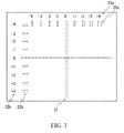
- optical axis misalignment correction An example of projection of a predetermined test pattern when there is optical axis misalignment is shown in FIG. 3 .
- both the R laser beam and the G laser beam may be projected to the same location on the projection plane based on pixel values of identical coordinates.
- the reference mark 21 will be displayed on the projection plane in yellow (the mixed color of the mixture of R and G), which is the correct display color, as illustrated in FIG. 2 .
- the display of the reference mark 21 may vary depending on whether or not there is optical axis misalignment in this way, the user can ascertain whether or not there is optical axis misalignment by observing the reference mark 21 that is displayed on the projection plane.
- the display of the bar marks 22 on the projection plane will be explained next.
- one of the pairs of the bar marks in the horizontal direction may be overlapping.
- the pair of bar marks labeled with the "-3" identifying information is overlapping and thus displayed in yellow (the mixed color that is the mixture of R and G) on the projection plane.
- one of the pairs of the bar marks in the vertical direction may be overlapping.
- the pair of bar marks labeled with the "-1" identifying information is overlapping and thus displayed in yellow (the mixed color that is the mixture of R and G) on the projection plane.
- the display of the bar marks 22 may change in this way depending on the degree of optical axis misalignment, the user is able to ascertain quantitatively the degree to which the optical axes are misaligned (the amount of misalignment) by observing the bar marks 22 displayed on the projection plane.
- the timing of the modulation may be adjusted for the R laser beam source 2c and the G laser beam source 2b by the correction data that corresponds to these indicators. If there is a partial overlapping of pairs of bar marks in two locations in the same direction, then the user can indicate the pair of bar marks with the greater overlap.
- FIG. 4 illustrates a case in which there has been no modification to the modulation timings for the individual laser beam sources 2, and the example of FIG. 4 (b) illustrates a case in which the modulation timings of the individual laser beam sources 2 have been modified.
- the region 31 is the region of the projection plane that is scanned by the R laser beam
- the region 32 is the region of the projection plane that is scanned by the G laser beam
- the region 33 is the region of the projection plane that is scanned by the B laser beam.
- R_HEN is the modulation timing for the horizontal scanning direction for the R laser beam source 2c
- G_HEN is the modulation timing for the horizontal scanning direction for the G laser beam source 2b
- B_HEN is the modulation timing for the horizontal scanning direction for the B laser beam source 2a.
- R_VEN is the modulation timing for the vertical scanning direction for the R laser beam source 2c
- G_VEN is the modulation timing for the vertical scanning direction for the G laser beam source 2b
- B_VEN is the modulation timing for the vertical scanning direction for the B laser beam source 2a.
- R_HEN, G_HEN, and B_HEN may all be identical, and the R projection region 31 may be dislocated to the right relative to the G projection region 32, and the B projection region 33 may be dislocated to the left relative to the G projection region 32.
- the modulation timings in the horizontal scan direction of the R laser beam source 2c and the B laser beam source 2a may be modified to delay R_HEN relative to G_HEN, and to advance B_HEN relative to G_HEN. Doing so causes the respective R, G, and B projection regions 31, 32 and 33 to all be identical in the horizontal direction.
- R_VEN, G_VEN, and B_VEN may all be identical, and the R projection region 31 may be dislocated downward relative to the G projection region 32, and the B projection region 33 may be dislocated upward relative to the G projection region 32.
- the modulation timings in the vertical scan direction of the R laser beam source 2c and the B laser beam source 2a may be modified to delay R_VEN relative to G_VEN, and to advance B_VEN relative to G_VEN. Doing so causes the respective R, G, and B projection regions 31, 32 and 33 to all be identical in the vertical direction.
- Performing the correction to the optical axes of the laser beams by modifying the modulation timings of the laser beam sources 2 is only an example.
- the adjustments to the optical axes of the laser beams may be performed through another method.
- a mechanism for controlling the arrangement of the laser beam sources 2 or the arrangement of the optical elements on the beam paths may be provided, and the optical axes of the laser beams may be adjusted by adjusting the arrangement of the laser beam sources 2 or of the optical elements.
- FIG. 5 illustrates another example of a predetermined test pattern.
- This test pattern includes a reference mark 41, in the shape of a +, displayed as a mixed color (white) combining all of the R, G, and B color components, and a plurality of bar marks 42 (42a, 42b, 42c, and 42d), displayed in the individual color components.
- R is indicated by dotted lines
- G is indicated by dotted and dashed lines
- B is indicated by double-dotted dashed lines
- white the mixed color of R, G, and B is by solid lines, so as to identify the individual colors, but in practice all are displayed as solid lines.
- the reference mark 41 indicates the horizontal and vertical reference positions.
- the plurality of bar marks 42 for each of the color components, may be arranged at predetermined intervals in the horizontal and vertical directions relative to the reference mark 41.
- bar marks 42a in the horizontal direction may be arranged on the top side of the reference mark 41
- bar marks 42b in the vertical direction may be arranged on the left side of the reference mark 41.
- bar marks 42c in the horizontal direction may be arranged on the bottom side of the reference mark 41 and bar marks 42d in the vertical direction may be arranged on the right side of the reference mark 41.
- the bar marks in the horizontal direction are labeled with identifying information 43a wherein the relationships with the reference position in the horizontal direction are quantified
- the bar marks in the vertical direction are labeled with identifying information 43b wherein the relationships with the reference position in the vertical direction are quantified
- the bar marks in the horizontal direction are labeled with identifying information 43c wherein the relationships with the reference position in the horizontal direction are quantified
- the bar marks in the vertical direction are labeled with identifying information 43d wherein the relationships with the reference position in the vertical direction are quantified.
- the user is able to ascertain, by displaying the test pattern only once, the optical axis misalignment of the R and G laser beams and the optical axis misalignment of the G and B laser beams. Moreover, respectively indicating the identifying information 43a and 43b for the pairs of bar marks in the horizontal and vertical direction, for the combination of R and G, and the identifying information 43c and 43d for the pairs of bar marks in the horizontal and vertical direction, for the combination of G and B, corrects the optical axis misalignment for all ofR, G, and B.
- the laser projector according to one or more embodiments of the present invention, it is possible to ascertain quantitatively the degree of optical axis misalignment by finding the pairs of bar marks in which there is overlapping when the reference mark is displayed on the projection plane in a state wherein the color components are separated, thus making recalibration of the optical axes easy.
Landscapes
- Engineering & Computer Science (AREA)
- Physics & Mathematics (AREA)
- Multimedia (AREA)
- Signal Processing (AREA)
- Computer Hardware Design (AREA)
- General Physics & Mathematics (AREA)
- Theoretical Computer Science (AREA)
- Optics & Photonics (AREA)
- Mechanical Optical Scanning Systems (AREA)
- Control Of Indicators Other Than Cathode Ray Tubes (AREA)
Abstract
Description
- The present invention relates to an image displaying device for projecting a color image by combining a plurality of laser beams of different color components.
- Various types of image displaying devices that display color images on a projection plane by combining laser beams of a red component (R), green component (G), and blue component (B), and projecting the images onto a projection plane, for example by a laser projector, have been commercialized.
- There have also been a variety of inventions proposed regarding such projection-type image displaying devices. For example, Patent Citation 1 discloses a projection-type display device having a plurality of optical signal generating means, driving means for each individual optical signal generating means, deflecting means provided in common for the optical signal generating means, and detecting means for detecting a dislocation angle of the deflecting means, wherein each driving means drive the respective optical signal generating means based on a detection result from the detecting means and based on a driving starting signal for each individual driving means.
-
Patent Citation 2, for example, discloses a projection-type image displaying device wherein an image that is free from color misalignment is displayed through scanning a beam with a time offset and modulating an image signal that is delayed by the time offset, and also achieves an improvement in safety and the display of a right image. -
Patent Citation 3, for example, discloses an image displaying device wherein the amount of misalignment between a scan timing signal and a synchronization signal is detected through optical detection and a pixel timing signal is shifted in accordance with the detected amount of misalignment, to drive the beam source, to thereby achieve a high quality image. -
- [Patent Citation 1]
Japanese Patent 3214211 - [Patent Citation 2]
Japanese Unexamined Patent Application Publication 2005-31529 - [Patent Citation 3] Japanese Unexamined Patent Application Publication
2007-25522 - In an image displaying device that combines laser beams of individual color components and projects an image onto a projection plane, it is necessary to align the optical axes of the individual laser beams. This is because the resolution is lost due to misalignment of the display positions for R, G, and B on the projection plane in the individual pixels because of misalignment of the optical axes of the individual laser beams (a shift in the relative relationship between the laser beams) due to variability in manufacturing and due to changes over time.
- Given this, conventionally, in order to correct optical axis misalignment, a test pattern, such as in
FIG. 6 , is projected, and a user adjusts the optical axes while viewing the test pattern that is displayed on the projection plane. That is, a reference mark, shaped as a +, for displaying a horizontal or vertical reference position is projected as a test pattern in a mixed color wherein all of the laser beams of the R, G, and B color components are combined. Given this, if thereference marks 61 are displayed on the projection plane such that they are separated into individual color components, this means that the optical axes are misaligned, so the optical axis misalignment is corrected through fine adjustments to the individual modulation timings of the respective beam sources, through user instructions, so as to produce a mixed color wherein theindividual reference marks 61 overlay each other. - In general, one or more embodiments of the present invention provide a technology that simplifies correcting of optical axis misalignment and wherein the amount of misalignment of the optical axes of the laser beams of the individual color components can be ascertained easily.
- In one aspect of the present invention, an image displaying device may comprise a plurality of laser beam sources configured to emit laser beams of mutually differing color components, wherein the image display device is configured to project, based on image data, an image by scanning the laser beams of mutually differing color components emitted from the plurality of laser beam sources, wherein the image data comprises image data of a predetermined test pattern. The predetermined test pattern may include a reference mark indicating at least one reference position, for example a horizontal and/or a vertical reference position, by a mixed color obtained by combining the mutually differing color components. The predetermined test pattern may also include, for each color component, a plurality of bar marks arranged at predetermined intervals in the horizontal direction relative to the reference markand/or a plurality of bar marks arranged at predetermined intervals in the vertical direction relative to the reference mark. The plurality of bar marks in the image data may be arranged such that the plurality of bar marks form, in at least one of the horizontal and vertical directions, pairs of bar marks of mutually differing color components with respect to the reference mark used as a reference. The pairs of bar marks of mutually differing color components may be formed, for example with respect to a distance from the reference marked used as reference. An amount of offset between the bar marks in each of the pairs of bar marks may increase by a predetermined increment, the predetermined increment being for example proportional to the distance thereof from the reference mark.
- In one or more embodiments of the present invention, the user may be able to evaluate whether or not there is optical axis misalignment by viewing the reference marks that are projected. That is, when the reference marks are displayed on the projection plane in a mixed color of the individual color components that are emitted from a plurality of laser beam sources, it can be determined that there is no optical axis misalignment, but if the reference marks are displayed on the projection plane in a state that is divided into individual color components, it can then be determined that there is optical axis misalignment.
- In one or more embodiments of the present invention, when there is optical axis misalignment, the user may be able to ascertain quantitatively the amount of optical axis misalignment (the amount of misalignment) by looking at a bar mark group that is displayed on the projection plane. That is, if, when there is optical axis misalignment, it is possible to find, from among the respective bar marks, those bar marks that overlay each other, then it is possible to back-calculate, from that pair of bar marks, the amount of optical axis misalignment. In this way, the image displaying device according to one or more embodiments of the present invention make it easy to ascertain the amount of misalignment of the optical axes of the laser beams of the individual color components, which is useful in the operation to correct optical axis misalignment.
- In one or more embodiments of the present invention, a reference mark may be a reference mark which indicates a reference position either horizontally or vertically, or may indicate reference positions both horizontally and vertically. Marks may be arranged at predetermined intervals relative to the reference mark, in either the horizontal or vertical direction, or may be arranged at predetermined intervals, relative to the reference mark, in both the horizontal and vertical directions.
- In one or more embodiments of the present invention, an image displaying device may comprise an operating portion configured to receive an indicator of the pairs of bar marks to be a reference for adjusting an optical axis of the laser beams. In one or more embodiments of the present invention, an image displaying device may further comprise a controlling portion configured to adjust an optical axis of the laser beams emitted from the laser beam sources by changing a modulation timing of the laser beam sources in accordance with the pair of bar marks that has been indicated as reference for adjusting an optical axis of the laser beams.
- In one or more embodiments of this configuration, the user may be able to perform the correction of the optical axis misalignment by merely finding and indicating the pair of bar marks wherein the bar marks overlap each other. If more than one pair of bar marks comprise bar marks overlapping each other, the pair of bar marks with the greater overlap may be indicated as reference for adjusting an optical axis of the laser beams.
- In one or more embodiments of the present invention, identification information may label the pairs of bar marks. In one or more embodiments of the present invention, the operating portion may receive an input of the identification information of the pair of bar marks as the indicator of the pairs of bar marks.
- For example, if, as a plurality of laser beam sources, a laser beam source that emits a red laser beam, a laser beam source that emits a green laser beam, and a laser beam source that emits a blue laser beam are provided, and if the display color for the identifying information for a pair of bar marks is green, thenthe identifying information for the pair of bar marks, displayed on a black background, may be read more easily by the human eye when compared to the case of a red or blue display color for the identifying information.
- In one or more embodiments of the present invention, the amount of optical axis misalignment of the laser beams of the individual color components may be ascertained easily, thus assisting in the operation to correct the optical axis misalignment.
- In a further aspect of the present invention, an image displaying method is provided. The image displaying method may comprise emitting laser beams of mutually differing color components, projecting, based on image data, an image by scanning the emitted laser beams of mutually differing color components, and using, as the image data, a predetermined test pattern. The predetermine test pattern may include a reference mark indicating at least one reference position, for example a horizontal and/or a vertical reference position, by a mixed color obtained by combining the mutually differing color components. The predetermine test pattern may also include, for each color component, a plurality of bar marks arranged at predetermined intervals in the horizontal direction relative to the reference mark and/or a plurality of bar marks arranged at predetermined intervals in the vertical direction relative to the reference mark. The method may also comprise arranging the plurality of bar marks in the image data such that the plurality of bar marks form pairs of bar marks of mutually differing color components with respect to the reference mark used as a reference. The pairs of bar marks of mutually differing color components may be formed with respect to a distance from the reference mark used as a reference. An amount of offset between the bar marks in each of the pairs of bar marks may increase by a predetermined increment, for example by an increment proportional to the distance thereof from the reference mark. Further embodiments of the image display device and of the image displaying method are defined in the dependent claims.
-
-
FIG. 1 is a diagram illustrating an example configuration of an image displaying device according to one or more embodiments of the present invention. -
FIG. 2 is a diagram illustrating an example of a test pattern used in an image displaying device according to one or more embodiments of the present invention. -
FIG. 3 is a diagram illustrating an example of projection of the test pattern when there is optical axis misalignment in an image displaying device according to one or more embodiments of the present invention. -
FIG. 4 is a diagram for explaining the relationship between the modulation timings of laser beam sources and the optical axis misalignment according to one or more embodiments of the present invention. -
FIG. 5 is a diagram illustrating another example of a test pattern used in an image displaying device according to one or more embodiments of the present invention. -
FIG. 6 is a diagram illustrating an example of a test pattern used in an image displaying device according to a conventional approach. - One or more embodiments of the present invention may apply to a variety of image displaying devices that display color images by combining laser beams of different color components that are outputted from a plurality of laser beam sources. In the following, reference will be made to a laser projector as an example of image displaying device.
-
FIG. 1 illustrates an example configuration of alaser projector 1 according to one or more embodiments. - The
laser projector 1 in one example may be structured from laser beam sources 2 (2a through 2c), variousoptical elements 3 through 5, ascanning mirror 6, and various driving and controllingunits 7 through 11. In thelaser projector 1, the individual laser beams of the red component (R), green component (G), and blue component (B) may be combined, and the combined beam may be projected onto a projection plane A, such as a screen or a wall, to project and display, on the projection plane A, a color image that depends on a video input signal. Moreover, in addition to these functional portions, the optical axes of the laser beams may be adjusted using a ROM (Read Only Memory) 12, a CPU (Central Processing Unit) 13, and anoperating portion 14. - The respective
laser beam sources 2 may be laser diodes (LDs) that output laser beams of mutually differing color components, and driven, mutually independently, by drive currents supplied individually from alaser driver 11, to each output a laser beam of a single color component. As a result, each laser beam source may emit a monochromatic component laser beam of a specific wavelength, such as a blue component (B) from thelaser beam source 2a, a green component (G) from thelaser beam source 2b, and a red component (R) from thelaser beam source 2c. -
Dichroic mirrors laser beam sources dichroic mirror 3 on the upstream side of the beam path and emitted to thedichroic mirror 4 on the downstream side of the beam path. In thedichroic mirror 4, this emitted combined beam may be further combined with the R laser beam emitted from thelaser beam source 2c to be emitted as the final combined color beam. - In this way, the
dichroic mirrors scanning mirror 6 through alens 5. - The
scanning mirror 6 may be dislocated, scanning in the horizontal direction (X) and the vertical direction (Y), through ascanning mirror driver 7 that inputs a driving signal from a scanningmirror controlling portion 8, and the color beam incident thereon may be reflected in accordance with the deflection angle thereof to be projected onto the projection plane A. In one example, an MEMS (Micro Electro Mechanical System) scanning mirror, which is useful in miniaturization, reduced power consumption, increased processing speed, and the like, may be used as thescanning mirror 6. - The
video processing portion 9 may sendvideo data at predetermined time intervals to the beamsource controlling portion 10, for example based on a video signal inputted from the outside, such as from a personal computer, or from theCPU 13, and the beamsource controlling portion 10 may obtain image information at predetermined scan positions thereby. - The beam
source controlling portion 10, based on the image information, may control thelaser driver 11 through a drive current waveform signal in order to project the video, comprising a plurality of pixels, in a projection range based on the image information. - The
laser driver 11 may drive the individuallaser beam sources 2a through 2c based on the control by thelaser controlling portion 10 to cause them to output the individual color component laser beams. - When a drive current of at least a threshold current is supplied from the
laser driver 11, the individuallaser beam source 2 may output a laser beam, where the greater the drive current, the greater the intensity of the laser beam that is outputted. Moreover, if a current less than the threshold current is supplied, the individuallaser beam source 2 may stop outputting the laser beam. - The
ROM 12 may store image data of a predetermined test pattern used in correcting the optical axis misalignment. In one example, image data for a predetermined test pattern such as presented illustratively inFIG. 2 may be stored. That is, for a combination of two colors (for example, R and G), a predetermined test pattern may be used that includes areference mark 21, for example shaped as a +, that is displayed by a mixed color wherein all of the color components of the two colors are combined, and a plurality of bar marks 22 (22a and 22b) displayed by the individual color components. - In the example of
FIG. 2 , for the colors for thereference mark 21 and bar marks 22, R is indicated by a dotted line, G is indicated by a line with dots and dashes, and yellow (the combined color wherein R and G are combined) is indicated by a solid line, to enable identification of the individual colors, but in practice all colors may be displayed as solid lines. - In the example of
FIG. 2 , thereference mark 21 shows horizontal and vertical reference positions. A plurality of bar marks 22 for each color component is arranged at predetermined intervals in each of the horizontal and vertical directions relative to thereference mark 21. In one example, the bar marks 22a for the horizontal direction may be arranged on the top side of thereference mark 21, and the bar marks 22b for the vertical direction may be arranged at the left side of thereference mark 21. Conversely, another arrangement wherein the bar marks 22a for the horizontal direction are arranged at the bottom side of thereference mark 21 and the bar marks 22b for the vertical direction are arranged on the right side of thereference mark 21 may be used instead. However, the predetermined test pattern may include a reference mark of a different shape: in any case, a plurality of bar marks for each color component is arranged at predetermined intervals along the directions set by the shape of the reference mark. - In the example of
Fig. 2 , bar marks 22 of different color components referenced to a distance from thereference mark 21 may together form a pair, which will be indicated as " pair of bar marks." Given this, the arrangement of the individual bar marks 22 may be an arrangement wherein the amount of offset between the bar marks 22 in an individual pair is increased by a predetermined increment, which may be a constant increment, for example proportional to the distance of the individual pair from thereference mark 21. That is, the arrangement may be such that the amount of offset between the bar marks 22 in the individual pairs of bar marks gradually increases when moving from the center of the screen toward the outside (that is, the relative positional relationship between the two parallel lines in each pair is shifted a bit at a time). In order to form the arrangement wherein the amount of offset between the bar marks 22 is increased a bit at a time, the bar marks 22 of each individual color may be arranged with constant spacing, where that spacing is different for each individual color of the bar marks 22. In one example, one of the pairs of bar marks may be superimposed together when there is optical axis misalignment: this may happen if the amount of increase in the amount of offset between the bar marks 22 matches the thickness of the bar marks 22. - Moreover, the pairs of bar marks in the horizontal direction may be labeled with identifying
information 23a that quantifies the relationships with the reference position in the horizontal direction, and the pairs of bar marks in the vertical direction may be labeled with identifyinginformation 23b that quantifies the relationships with the reference position in the vertical direction. The display color for the identifying information 23 (23a and 23b) may use R or G (and for example G), which are colors that are easily read when using a black background. Moreover, the identifying information 23 may enable unique identification of each pair of bar marks by the user, and may be expressed using letters, numbers, or the like. - The
ROM 12 may store correction data corresponding to the respective horizontal and vertical identifying information 23 in the predetermined test pattern. The correction data may be specified by the amount of adjustment in the modulation timing of alaser beam source 2 corresponding to the amount of correction in the optical axes necessary to eliminate the existing amount of misalignment in the pairs of bar marks (the amount of misalignment in the image data). This may use the change in the optical axis of the laser beam emitted from the applicablelaser beam source 2 through a change in the modulation timing of thelaser beam source 2. However, another structure may be used wherein the amount of misalignment of the pairs of bar marks, or the amount of correction for the optical axes, may be specified in the correction data to produce the amount by which the modulation timing of thelaser beam source 2 is adjusted through a predetermined formula to convert from the amount of misalignment or the amount of correction. - The predetermined test pattern in the example of
FIG. 2 is a test pattern for two of the R, G, and B colors, and can be used for correcting the optical axis misalignment for the laser beams of any of the colors through changing the combination of colors. For example, it is possible to correct all of the optical axis misalignment for R, G, and B by correcting the optical axis misalignment using a test pattern for the combination of R and G and correcting the optical axis misalignment using a test pattern for the combination of G and B (or R and B). - When an instruction to project the predetermined test pattern is received from a user through the operating
portion 14, theCPU 13 may read in the image data for the predetermined test pattern from theROM 12 and outputs it to thevideo processing portion 9. In one example, an instruction for the two colors that will be subject to optical axis misalignment correction may be received from a user, and a video signal obtained by applying that color information to the image data read out from theROM 12 may be outputted to thevideo processing portion 9. This causes a test pattern that uses the two colors specified by the user to be displayed on the projection plane. - Moreover, when an indicator for a pair of bar marks that will be the reference for correcting the optical axis misalignment is received from a user through the operating
portion 14, theCPU 13 may read out from theROM 12 the correction data that corresponds to the pair of bar marks that has been indicated by the indicator, and output it to the beamsource controlling portion 10. This causes the optical axis of the laser beam that is emitted from thelaser beam source 2 to be changed by an amount depending on the pair of bar marks indicated by the user. - An example of a case wherein correcting the optical axis misalignment for the combination of R and G is indicated by a user will be explained as an example of optical axis misalignment correction. An example of projection of a predetermined test pattern when there is optical axis misalignment is shown in
FIG. 3 . - The display of the
reference mark 21 on the projection plane will be explained first. If there is no optical axis misalignment in the R and G laser beams, then both the R laser beam and the G laser beam may be projected to the same location on the projection plane based on pixel values of identical coordinates. As a result, thereference mark 21 will be displayed on the projection plane in yellow (the mixed color of the mixture of R and G), which is the correct display color, as illustrated inFIG. 2 . - On the other hand, if there is optical axis misalignment between the R and G laser beams, then even an R laser beam and a G laser beam based on pixel values having identical coordinates may be projected onto different locations on the projection plane. As a result, the
reference mark 21, as illustrated inFIG. 3 , may be displayed on the projection plane such that the R and G are separated. - Since the display of the
reference mark 21 may vary depending on whether or not there is optical axis misalignment in this way, the user can ascertain whether or not there is optical axis misalignment by observing thereference mark 21 that is displayed on the projection plane. - The display of the bar marks 22 on the projection plane will be explained next. When there is optical axis misalignment in the horizontal direction in the R and G laser beams, then one of the pairs of the bar marks in the horizontal direction may be overlapping. In the example in
FIG. 3 , among the pairs of bar marks in the horizontal direction, the pair of bar marks labeled with the "-3" identifying information is overlapping and thus displayed in yellow (the mixed color that is the mixture of R and G) on the projection plane. - Moreover, when there is optical axis misalignment in the vertical direction in the R and G laser beams, then one of the pairs of the bar marks in the vertical direction may be overlapping. In the example in
FIG. 3 , among the pairs of bar marks in the vertical direction, the pair of bar marks labeled with the "-1" identifying information is overlapping and thus displayed in yellow (the mixed color that is the mixture of R and G) on the projection plane. - Since the display of the bar marks 22 may change in this way depending on the degree of optical axis misalignment, the user is able to ascertain quantitatively the degree to which the optical axes are misaligned (the amount of misalignment) by observing the bar marks 22 displayed on the projection plane. In this case, if the user operates the operating
portion 14 to indicate "-3" in the horizontal direction and "-1" in the vertical direction, the timing of the modulation may be adjusted for the Rlaser beam source 2c and the Glaser beam source 2b by the correction data that corresponds to these indicators. If there is a partial overlapping of pairs of bar marks in two locations in the same direction, then the user can indicate the pair of bar marks with the greater overlap. - While the explanation above refers to a case wherein the user indicates the display of a test pattern, and the correction of optical axis misalignment, for a combination of R and G, it is possible to align all of the optical axes for R, G, and B by performing the same operation for a combination of G and B (or R and B) as well.
- The modification to the modulation timings of the laser beam sources will be explained next with reference to
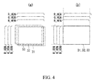
FIG. 4 . The example ofFIG. 4 (a) illustrates a case in which there has been no modification to the modulation timings for the individuallaser beam sources 2, and the example ofFIG. 4 (b) illustrates a case in which the modulation timings of the individuallaser beam sources 2 have been modified. - In the example shown in
FIG. 4 , theregion 31 is the region of the projection plane that is scanned by the R laser beam, theregion 32 is the region of the projection plane that is scanned by the G laser beam, and theregion 33 is the region of the projection plane that is scanned by the B laser beam. - Moreover, R_HEN is the modulation timing for the horizontal scanning direction for the R
laser beam source 2c, G_HEN is the modulation timing for the horizontal scanning direction for the Glaser beam source 2b, and B_HEN is the modulation timing for the horizontal scanning direction for the Blaser beam source 2a. - Moreover, R_VEN is the modulation timing for the vertical scanning direction for the R
laser beam source 2c, G_VEN is the modulation timing for the vertical scanning direction for the Glaser beam source 2b, and B_VEN is the modulation timing for the vertical scanning direction for the Blaser beam source 2a. - When there has been no modification in the modulation timings, R_HEN, G_HEN, and B_HEN may all be identical, and the
R projection region 31 may be dislocated to the right relative to theG projection region 32, and theB projection region 33 may be dislocated to the left relative to theG projection region 32. In this case, as illustrated inFIG. 4 (b) , the modulation timings in the horizontal scan direction of the Rlaser beam source 2c and the Blaser beam source 2a may be modified to delay R_HEN relative to G_HEN, and to advance B_HEN relative to G_HEN. Doing so causes the respective R, G, andB projection regions - Moreover, when there has been no modification in the modulation timings, R_VEN, G_VEN, and B_VEN may all be identical, and the
R projection region 31 may be dislocated downward relative to theG projection region 32, and theB projection region 33 may be dislocated upward relative to theG projection region 32. In this case, as illustrated inFIG. 4 (b) , the modulation timings in the vertical scan direction of the Rlaser beam source 2c and the Blaser beam source 2a may be modified to delay R_VEN relative to G_VEN, and to advance B_VEN relative to G_VEN. Doing so causes the respective R, G, andB projection regions - Performing the correction to the optical axes of the laser beams by modifying the modulation timings of the
laser beam sources 2 is only an example. Thus, the adjustments to the optical axes of the laser beams may be performed through another method. For example, a mechanism for controlling the arrangement of thelaser beam sources 2 or the arrangement of the optical elements on the beam paths may be provided, and the optical axes of the laser beams may be adjusted by adjusting the arrangement of thelaser beam sources 2 or of the optical elements. -
FIG. 5 illustrates another example of a predetermined test pattern. This test pattern includes areference mark 41, in the shape of a +, displayed as a mixed color (white) combining all of the R, G, and B color components, and a plurality of bar marks 42 (42a, 42b, 42c, and 42d), displayed in the individual color components. - In the example of
FIG. 5 , for the colors for thereference mark 41 and the bar marks 42, R is indicated by dotted lines, G is indicated by dotted and dashed lines, the B is indicated by double-dotted dashed lines, and white (the mixed color of R, G, and B) is by solid lines, so as to identify the individual colors, but in practice all are displayed as solid lines. - In the example of
FIG. 5 , thereference mark 41 indicates the horizontal and vertical reference positions. The plurality of bar marks 42, for each of the color components, may be arranged at predetermined intervals in the horizontal and vertical directions relative to thereference mark 41. In one example, for the combination of R and G, bar marks 42a in the horizontal direction may be arranged on the top side of thereference mark 41, and bar marks 42b in the vertical direction may be arranged on the left side of thereference mark 41. Moreover, for the combination of G and B, bar marks 42c in the horizontal direction may be arranged on the bottom side of thereference mark 41 andbar marks 42d in the vertical direction may be arranged on the right side of thereference mark 41. These arrangements are only examples, and a different form of arrangement could be used instead. - Continuing with the example of
FIG. 5 , for the combination of R and G, the bar marks in the horizontal direction are labeled with identifyinginformation 43a wherein the relationships with the reference position in the horizontal direction are quantified, and the bar marks in the vertical direction are labeled with identifyinginformation 43b wherein the relationships with the reference position in the vertical direction are quantified. In addition, for the combination of G and B, the bar marks in the horizontal direction are labeled with identifyinginformation 43c wherein the relationships with the reference position in the horizontal direction are quantified, and the bar marks in the vertical direction are labeled with identifyinginformation 43d wherein the relationships with the reference position in the vertical direction are quantified. - In one or more embodiments, given this type of predetermined test pattern, the user is able to ascertain, by displaying the test pattern only once, the optical axis misalignment of the R and G laser beams and the optical axis misalignment of the G and B laser beams. Moreover, respectively indicating the identifying
information information - As described above, with the laser projector according to one or more embodiments of the present invention, it is possible to ascertain quantitatively the degree of optical axis misalignment by finding the pairs of bar marks in which there is overlapping when the reference mark is displayed on the projection plane in a state wherein the color components are separated, thus making recalibration of the optical axes easy.
- While the invention has been described with respect to a limited number of embodiments, those skilled in the art, having benefit of this disclosure, will appreciate that other embodiments can be devised which do not depart from the scope of the invention as claimed. Furthermore, those of ordinary skill in the art will appreciate that certain components or "portions" of one or more embodiments of the present invention may be implemented by a circuit, processor, etc. using known methods. Accordingly, the scope of the invention should be limited only by the attached claims.
-
- 1:
- Laser Projector
- 2 (2a through 2c):
- Laser Beam Sources
- 3, 4:
- Dichroic Mirrors
- 5:
- Lens
- 6:
- Scanning Mirror
- 7:
- Scanning Mirror Driver
- 8:
- Scanning Mirror Controlling Portion
- 9:
- Video Processing Portion
- 10:
- Beam Source Controlling Portion
- 11:
- Laser Driver
- 12:
- ROM
- 13:
- CPU
- 14:
- Operating Portion
Claims (8)
- An image displaying device (1) comprising:a plurality of laser beam sources (2) configured to emit laser beams of mutually differing color components,wherein the image display device is configured to project, based on image data, an image by scanning the laser beams of mutually differing color components emitted from the plurality of laser beam sources (2),wherein the image data comprises image data of a test pattern including:a reference mark (21; 41) indicating horizontal and vertical reference positions by a mixed color obtained by combining the mutually differing color components; andfor each color component, a plurality of bar marks (22; 42) arranged at predetermined intervals in the horizontal and vertical directions relative to the reference mark (21; 42), andwherein the plurality of bar marks (22; 42) in the image data is arranged such that:the plurality of bar marks (22; 42) form pairs of bar marks (22; 42) of mutually differing color components with respect to a distance from the reference mark (21; 41) used as a reference, andan amount of offset between the bar marks (22; 42) in each of the pairs of bar marks (22; 42) increases by an increment proportional to the distance from the reference mark (21; 41).
- The image displaying device of claim 1, further comprising:an operating portion (14) configured to receive an indicator of the pairs of bar marks (22; 42) to be a reference for adjusting an optical axis of the laser beams; anda controlling portion (8, 10) configured to adjust an optical axis of the laser beams emitted from the laser beam sources (2) by changing a modulation timing of the laser beam sources (2) in accordance with the pair of bar marks (22; 42) indicated as reference.
- The image displaying device (1) of claim 2,
wherein identification information (23; 43) labels the pairs of bar marks (22; 42), and
wherein the operating portion (14) receives an input of the identification information (23; 43) of the pairs of bar marks (22; 42) as the indicator of the pairs of bar marks (22; 42). - The image displaying device of any of claims 1-3,
wherein the plurality of laser beam sources (2) comprises:a laser beam source (2c) configured to emit a red laser beam;a laser beam source (2b) configured to emit a green laser beam; anda laser beam source (2a) configured to emit a blue laser beam, and wherein a display color for the identification information (23, 43) for the barmarks (22; 42) is green. - An image displaying method comprising:emitting laser beams of mutually differing color components;projecting, based on image data, an image by scanning the emitted laser beams of mutually differing color components;using, as the image data, a test pattern including:a reference mark (21; 41) indicating horizontal and vertical reference positions by a mixed color obtained by combining the mutually differing color components; andfor each color component, a plurality of bar marks (22; 42) arranged at predetermined intervals in the horizontal and vertical directions relative to the reference mark (21; 41) andarranging the plurality of bar marks (22; 42) in the image data such that:the plurality of bar marks (22; 42) form pairs of bar marks (22; 42) of mutually differing color components with respect to a distance from the reference mark (21; 41) used as a reference, and an amount of offset between the bar marks (22; 42) in each of the pairs of bar marks (22; 42) increases by an increment proportional to the distance from the reference mark (21; 41).
- The image displaying method of claim 5, further comprising:receiving an indicator of the pairs of bar marks (22; 42) to be a reference for adjusting an optical axis of the laser beams; andadjusting an optical axis of the laser beams emitted from the laser beam sources (2) by changing a modulation timing of laser beam sources (2) emitting the laser beams in accordance with the pair of bar marks (22; 42) indicated as reference.
- The image displaying method of claim 6, further comprising:using identification information (23; 43) to label the pairs of bar marks (22; 42); andreceiving an input of the identification information (23; 43) of the pair of bar marks (22) as the indicator of the pairs of bar marks (22).
- The image displaying method of any of claims 5-7, wherein
using, as the plurality of laser beam sources (2), a laser beam source (2c) emitting a red laser beam, a laser beam source (2b) emitting a green laser beam, and a laser beam source (2a) emitting a blue laser beam, and
using green as a display color for the identification information (23; 43) for the
bar marks (22; 42).
Applications Claiming Priority (1)
| Application Number | Priority Date | Filing Date | Title |
|---|---|---|---|
| JP2012269114A JP5983375B2 (en) | 2012-12-10 | 2012-12-10 | Image display device |
Publications (1)
| Publication Number | Publication Date |
|---|---|
| EP2741500A1 true EP2741500A1 (en) | 2014-06-11 |
Family
ID=49378139
Family Applications (1)
| Application Number | Title | Priority Date | Filing Date |
|---|---|---|---|
| EP13188773.9A Withdrawn EP2741500A1 (en) | 2012-12-10 | 2013-10-15 | Image displaying device |
Country Status (3)
| Country | Link |
|---|---|
| US (1) | US9202434B2 (en) |
| EP (1) | EP2741500A1 (en) |
| JP (1) | JP5983375B2 (en) |
Cited By (1)
| Publication number | Priority date | Publication date | Assignee | Title |
|---|---|---|---|---|
| ITUA20163018A1 (en) * | 2016-04-29 | 2017-10-29 | St Microelectronics Ltd | DEVICE AND METHOD FOR AUTOMATIC COLOR CALIBRATION IN A LASER SCANNING DEVICE |
Citations (5)
| Publication number | Priority date | Publication date | Assignee | Title |
|---|---|---|---|---|
| JP3214211B2 (en) | 1993-03-16 | 2001-10-02 | ミノルタ株式会社 | Projection display device |
| JP2005031529A (en) | 2003-07-09 | 2005-02-03 | Sony Corp | Projection type image display device |
| JP2007025522A (en) | 2005-07-21 | 2007-02-01 | Seiko Epson Corp | Image display device and control method of image display device |
| US20090027567A1 (en) * | 2007-07-25 | 2009-01-29 | Sony Corporation | Projection display apparatus |
| US20090153749A1 (en) * | 2007-12-14 | 2009-06-18 | Stephen Randall Mixon | Portable projector background color correction scheme |
Family Cites Families (3)
| Publication number | Priority date | Publication date | Assignee | Title |
|---|---|---|---|---|
| US7273281B2 (en) * | 2003-12-31 | 2007-09-25 | Symbol Technologies, Inc. | Method and apparatus for aligning a plurality of lasers in an electronic display device |
| JP2006184770A (en) * | 2004-12-28 | 2006-07-13 | Fuji Photo Film Co Ltd | Color image display apparatus |
| US8451195B2 (en) * | 2006-02-15 | 2013-05-28 | Prysm, Inc. | Servo-assisted scanning beam display systems using fluorescent screens |
-
2012
- 2012-12-10 JP JP2012269114A patent/JP5983375B2/en not_active Expired - Fee Related
-
2013
- 2013-10-04 US US14/046,128 patent/US9202434B2/en not_active Expired - Fee Related
- 2013-10-15 EP EP13188773.9A patent/EP2741500A1/en not_active Withdrawn
Patent Citations (5)
| Publication number | Priority date | Publication date | Assignee | Title |
|---|---|---|---|---|
| JP3214211B2 (en) | 1993-03-16 | 2001-10-02 | ミノルタ株式会社 | Projection display device |
| JP2005031529A (en) | 2003-07-09 | 2005-02-03 | Sony Corp | Projection type image display device |
| JP2007025522A (en) | 2005-07-21 | 2007-02-01 | Seiko Epson Corp | Image display device and control method of image display device |
| US20090027567A1 (en) * | 2007-07-25 | 2009-01-29 | Sony Corporation | Projection display apparatus |
| US20090153749A1 (en) * | 2007-12-14 | 2009-06-18 | Stephen Randall Mixon | Portable projector background color correction scheme |
Cited By (2)
| Publication number | Priority date | Publication date | Assignee | Title |
|---|---|---|---|---|
| ITUA20163018A1 (en) * | 2016-04-29 | 2017-10-29 | St Microelectronics Ltd | DEVICE AND METHOD FOR AUTOMATIC COLOR CALIBRATION IN A LASER SCANNING DEVICE |
| US9942531B2 (en) | 2016-04-29 | 2018-04-10 | Stmicroelectronics Ltd | Device and method for automatic color calibration in a laser scanning apparatus |
Also Published As
| Publication number | Publication date |
|---|---|
| US20140160141A1 (en) | 2014-06-12 |
| JP5983375B2 (en) | 2016-08-31 |
| US9202434B2 (en) | 2015-12-01 |
| JP2014115440A (en) | 2014-06-26 |
Similar Documents
| Publication | Publication Date | Title |
|---|---|---|
| US9936176B2 (en) | Image protection device and adjustment method | |
| US10944945B2 (en) | Projection device and projection method, projection module, electronic device, and program | |
| US9800844B2 (en) | Image projection apparatus | |
| CN102365866B (en) | Multiprojection display system and screen forming method | |
| US20190020858A1 (en) | Light emitter architecture for scanning display device | |
| US10564436B2 (en) | Projecting apparatus, projecting module, and electronic instrument | |
| US20140285777A1 (en) | Projection apparatus, projection method, and program medium for projection | |
| CN103676145A (en) | Image display apparatus and optical component | |
| US20140063472A1 (en) | Laser Scanning Projection Apparatus with Phase Detection and Compensation | |
| US20180192018A1 (en) | Projection device and projection method, projection module, electronic device, and program | |
| JP3214211B2 (en) | Projection display device | |
| US20120327373A1 (en) | Scan-type image display device | |
| US8422107B2 (en) | Optical scanning device, image display device and retinal scanning display | |
| JP2011154324A (en) | Image display apparatus | |
| EP3596529A1 (en) | Laser scanning display with luminance adjustment | |
| US20130162960A1 (en) | Image Display Device | |
| JP2007171228A (en) | Image display system | |
| US9202434B2 (en) | Image displaying device | |
| WO2013047656A1 (en) | Image projecting apparatus and method for correcting for optical axis deviation | |
| JP5731660B2 (en) | Projection apparatus, control method, and program | |
| CN117315013B (en) | A scanning trajectory discrimination method and scanning display device | |
| JP2008191466A (en) | Projection display | |
| KR102210710B1 (en) | Layer display device and operation method thereof | |
| JP2016099561A (en) | Projection apparatus, projection method, program, and storage medium | |
| WO2013035142A1 (en) | Optical axis offset correcting device, control method, and heads-up display |
Legal Events
| Date | Code | Title | Description |
|---|---|---|---|
| PUAI | Public reference made under article 153(3) epc to a published international application that has entered the european phase |
Free format text: ORIGINAL CODE: 0009012 |
|
| 17P | Request for examination filed |
Effective date: 20131015 |
|
| AK | Designated contracting states |
Kind code of ref document: A1 Designated state(s): AL AT BE BG CH CY CZ DE DK EE ES FI FR GB GR HR HU IE IS IT LI LT LU LV MC MK MT NL NO PL PT RO RS SE SI SK SM TR |
|
| AX | Request for extension of the european patent |
Extension state: BA ME |
|
| R17P | Request for examination filed (corrected) |
Effective date: 20141209 |
|
| RBV | Designated contracting states (corrected) |
Designated state(s): AL AT BE BG CH CY CZ DE DK EE ES FI FR GB GR HR HU IE IS IT LI LT LU LV MC MK MT NL NO PL PT RO RS SE SI SK SM TR |
|
| 17Q | First examination report despatched |
Effective date: 20150702 |
|
| GRAP | Despatch of communication of intention to grant a patent |
Free format text: ORIGINAL CODE: EPIDOSNIGR1 |
|
| STAA | Information on the status of an ep patent application or granted ep patent |
Free format text: STATUS: GRANT OF PATENT IS INTENDED |
|
| RIC1 | Information provided on ipc code assigned before grant |
Ipc: G09G 5/02 20060101ALI20170510BHEP Ipc: H04N 9/31 20060101AFI20170510BHEP |
|
| INTG | Intention to grant announced |
Effective date: 20170602 |
|
| STAA | Information on the status of an ep patent application or granted ep patent |
Free format text: STATUS: THE APPLICATION IS DEEMED TO BE WITHDRAWN |
|
| 18D | Application deemed to be withdrawn |
Effective date: 20171013 |