EP2741347A1 - Top cap assembly having a novel structure - Google Patents
Top cap assembly having a novel structure Download PDFInfo
- Publication number
- EP2741347A1 EP2741347A1 EP12844228.2A EP12844228A EP2741347A1 EP 2741347 A1 EP2741347 A1 EP 2741347A1 EP 12844228 A EP12844228 A EP 12844228A EP 2741347 A1 EP2741347 A1 EP 2741347A1
- Authority
- EP
- European Patent Office
- Prior art keywords
- top cap
- cap assembly
- pcb
- terminal
- pcm
- Prior art date
- Legal status (The legal status is an assumption and is not a legal conclusion. Google has not performed a legal analysis and makes no representation as to the accuracy of the status listed.)
- Granted
Links
Images


Classifications
-
- H—ELECTRICITY
- H01—ELECTRIC ELEMENTS
- H01M—PROCESSES OR MEANS, e.g. BATTERIES, FOR THE DIRECT CONVERSION OF CHEMICAL ENERGY INTO ELECTRICAL ENERGY
- H01M50/00—Constructional details or processes of manufacture of the non-active parts of electrochemical cells other than fuel cells, e.g. hybrid cells
- H01M50/50—Current conducting connections for cells or batteries
- H01M50/531—Electrode connections inside a battery casing
-
- H—ELECTRICITY
- H01—ELECTRIC ELEMENTS
- H01M—PROCESSES OR MEANS, e.g. BATTERIES, FOR THE DIRECT CONVERSION OF CHEMICAL ENERGY INTO ELECTRICAL ENERGY
- H01M10/00—Secondary cells; Manufacture thereof
- H01M10/42—Methods or arrangements for servicing or maintenance of secondary cells or secondary half-cells
- H01M10/425—Structural combination with electronic components, e.g. electronic circuits integrated to the outside of the casing
-
- H—ELECTRICITY
- H01—ELECTRIC ELEMENTS
- H01M—PROCESSES OR MEANS, e.g. BATTERIES, FOR THE DIRECT CONVERSION OF CHEMICAL ENERGY INTO ELECTRICAL ENERGY
- H01M10/00—Secondary cells; Manufacture thereof
- H01M10/05—Accumulators with non-aqueous electrolyte
- H01M10/052—Li-accumulators
-
- H—ELECTRICITY
- H01—ELECTRIC ELEMENTS
- H01M—PROCESSES OR MEANS, e.g. BATTERIES, FOR THE DIRECT CONVERSION OF CHEMICAL ENERGY INTO ELECTRICAL ENERGY
- H01M50/00—Constructional details or processes of manufacture of the non-active parts of electrochemical cells other than fuel cells, e.g. hybrid cells
- H01M50/10—Primary casings; Jackets or wrappings
- H01M50/147—Lids or covers
-
- H—ELECTRICITY
- H01—ELECTRIC ELEMENTS
- H01M—PROCESSES OR MEANS, e.g. BATTERIES, FOR THE DIRECT CONVERSION OF CHEMICAL ENERGY INTO ELECTRICAL ENERGY
- H01M50/00—Constructional details or processes of manufacture of the non-active parts of electrochemical cells other than fuel cells, e.g. hybrid cells
- H01M50/10—Primary casings; Jackets or wrappings
- H01M50/147—Lids or covers
- H01M50/148—Lids or covers characterised by their shape
- H01M50/15—Lids or covers characterised by their shape for prismatic or rectangular cells
-
- H—ELECTRICITY
- H01—ELECTRIC ELEMENTS
- H01M—PROCESSES OR MEANS, e.g. BATTERIES, FOR THE DIRECT CONVERSION OF CHEMICAL ENERGY INTO ELECTRICAL ENERGY
- H01M50/00—Constructional details or processes of manufacture of the non-active parts of electrochemical cells other than fuel cells, e.g. hybrid cells
- H01M50/50—Current conducting connections for cells or batteries
- H01M50/543—Terminals
- H01M50/547—Terminals characterised by the disposition of the terminals on the cells
- H01M50/55—Terminals characterised by the disposition of the terminals on the cells on the same side of the cell
-
- H—ELECTRICITY
- H01—ELECTRIC ELEMENTS
- H01M—PROCESSES OR MEANS, e.g. BATTERIES, FOR THE DIRECT CONVERSION OF CHEMICAL ENERGY INTO ELECTRICAL ENERGY
- H01M50/00—Constructional details or processes of manufacture of the non-active parts of electrochemical cells other than fuel cells, e.g. hybrid cells
- H01M50/50—Current conducting connections for cells or batteries
- H01M50/543—Terminals
- H01M50/552—Terminals characterised by their shape
- H01M50/553—Terminals adapted for prismatic, pouch or rectangular cells
-
- H—ELECTRICITY
- H01—ELECTRIC ELEMENTS
- H01M—PROCESSES OR MEANS, e.g. BATTERIES, FOR THE DIRECT CONVERSION OF CHEMICAL ENERGY INTO ELECTRICAL ENERGY
- H01M50/00—Constructional details or processes of manufacture of the non-active parts of electrochemical cells other than fuel cells, e.g. hybrid cells
- H01M50/50—Current conducting connections for cells or batteries
- H01M50/572—Means for preventing undesired use or discharge
-
- H—ELECTRICITY
- H01—ELECTRIC ELEMENTS
- H01M—PROCESSES OR MEANS, e.g. BATTERIES, FOR THE DIRECT CONVERSION OF CHEMICAL ENERGY INTO ELECTRICAL ENERGY
- H01M2200/00—Safety devices for primary or secondary batteries
- H01M2200/10—Temperature sensitive devices
- H01M2200/106—PTC
-
- Y—GENERAL TAGGING OF NEW TECHNOLOGICAL DEVELOPMENTS; GENERAL TAGGING OF CROSS-SECTIONAL TECHNOLOGIES SPANNING OVER SEVERAL SECTIONS OF THE IPC; TECHNICAL SUBJECTS COVERED BY FORMER USPC CROSS-REFERENCE ART COLLECTIONS [XRACs] AND DIGESTS
- Y02—TECHNOLOGIES OR APPLICATIONS FOR MITIGATION OR ADAPTATION AGAINST CLIMATE CHANGE
- Y02E—REDUCTION OF GREENHOUSE GAS [GHG] EMISSIONS, RELATED TO ENERGY GENERATION, TRANSMISSION OR DISTRIBUTION
- Y02E60/00—Enabling technologies; Technologies with a potential or indirect contribution to GHG emissions mitigation
- Y02E60/10—Energy storage using batteries
Definitions
- the present invention relates to a top cap assembly having a novel structure, and, more particularly, to a top cap assembly mounted to a battery cell having an electrode assembly disposed in a battery case together with an electrolyte in a sealed state, the battery case being provided at an upper end thereof with a first electrode terminal and a second electrode terminal, the top cap assembly including a protection circuit module (PCM) and an electrically insulative top cap housing mounted to the upper end of the battery cell while surrounding an outside of the PCM, wherein the PCM includes a protection circuit board (PCB) having a protection circuit formed thereon, the PCB being coupled to a mechanical coupling part of a terminal block, connecting parts connected to the first electrode terminal and the second electrode terminal, a safety element, and the terminal block mounted to the PCM, the terminal block including connectors.
- PCM protection circuit module
- PCB protection circuit board
- the lithium secondary battery may be heated or explode due to the overcharge of the battery, the overcurrent in the battery, or external physical impact. That is, the safety of the lithium secondary battery is very low. Consequently, safety elements, such as a positive temperature coefficient (PTC) element and a protection circuit module (PCM), to effectively control an abnormal state of the lithium secondary battery, such as the overcharge of the lithium secondary battery or the overcurrent in the lithium secondary battery, are mounted to a battery cell in a state in which the safety elements are connected to the battery cell.
- PTC positive temperature coefficient
- PCM protection circuit module
- a PCM is inserted into a top cap housing and is coupled to the top cap housing by welding or soldering. That is, the PCM is inserted into the top cap housing, in which a connecter is assembled, and is coupled to the top cap housing by welding or soldering so that the PCM is connected to a top cap assembly, and the top cap assembly is coupled to a battery cell. In this way, a battery pack is manufactured.
- soldering tolerance is unavoidable, and therefore, it is necessary to increase the length of electric components constituting the battery pack with the result that the capacity of the battery cell is reduced.
- the present invention has been made to solve the above problems, and other technical problems that have yet to be resolved.
- PCM protection circuit module
- a top cap assembly mounted to a battery cell having an electrode assembly of a cathode/separator/anode structure disposed in a battery case together with an electrolyte in a sealed state, the battery case being provided at an upper end thereof with a first electrode terminal and a second electrode terminal, the top cap assembly including a protection circuit module (PCM) and an electrically insulative top cap housing mounted to the upper end of the battery cell while surrounding an outside of the PCM, wherein the PCM includes a protection circuit board (PCB) having a protection circuit formed thereon, the PCB being coupled to a mechanical coupling part of a terminal block, connecting parts connected to the first electrode terminal and the second electrode terminal, a safety element, and the terminal block mounted to the PCM, the terminal block including connectors.
- PCM protection circuit module
- PCB protection circuit board
- the terminal block may be coupled to the PCM through a simple assembly process.
- movement between components is minimized, and therefore, the top cap assembly has a very stable structure.
- the first electrode terminal may be a cathode terminal
- the second electrode terminal may be an anode terminal
- a prismatic battery cell is configured to have a structure in which an electrode terminal protruding from the upper end of the prismatic battery cell and a battery case form an anode terminal and a cathode terminal, respectively, and an insulation member, such as a gasket, is disposed between the anode terminal and the cathode terminal.
- the first electrode terminal may be a cathode terminal, which is the upper end of the battery case
- the second electrode terminal may be an anode terminal protruding from the upper end of the battery case.
- the connecting parts may be formed at the bottom of the PCB.
- the connecting parts may be formed at positions corresponding to the first electrode terminal and the second electrode terminal.
- the mechanical coupling part may include a fastening protrusion protruding downward from a lower end of the terminal block, and the PCB may be provided with a fastening groove formed at a position corresponding to the fastening protrusion.
- the terminal block may be easily mounted to the PCB through coupling between the fastening protrusion and the fastening groove, thereby simplifying an assembly process and improving mechanical stability.
- the terminal block may have at least one hook protruding downward therefrom to fixedly fasten the PCB while surrounding the outside of the PCB in a state in which the fastening protrusion is inserted in the fastening groove in order to secure a more stable coupling state.
- the protruding height of the fastening protrusion may be equal to the thickness ofthe PCB. If the protruding height of the fastening protrusion is too low, the fastening protrusion may not function with the result that coupling force between the fastening protrusion and the fastening groove may be decreased. On the other hand, if the protruding height ofthe fastening protrusion is too high, the volume ofthe top cap assembly is increased, which is not preferable. In consideration of the above matters, therefore, the protruding height ofthe fastening protrusion is properly set. It is preferable for the protruding height of the fastening protrusion to be equal to the thickness of the PCB as described above.
- the terminal block may be provided at one major surface thereof with a guide lip for mechanical fastening with the top cap housing and hooks disposed at opposite sides of the guide lip.
- the top cap housing may be provided with a terminal lip, which is provided between tapered parts, and a pair of slit opening corresponding to the guide lip and the hooks, respectively.
- the protruding terminal lip is formed between the tapered parts.
- the hooks and the guide lip are respectively fastened to the terminal lip and the slit openings when the top cap housing is mounted to the PCM.
- the movement between the top cap housing, the terminal block, and the PCM is minimized, thereby improving assembly accuracy.
- a soldering process is omitted, and therefore, the total length of the battery cell is increased, thereby maximizing the capacity of the battery cell.
- the connectors of the terminal block may be mounted to the PCB using surface mounting technology (SMT).
- SMT surface mounting technology
- SMT is widely used to mount surface mount type parts to an electronic board, such as a printed circuit board (PCB).
- PCB printed circuit board
- the safety element may be an element, the resistance of which is increased as the temperature of the element is increased.
- the safety element is a positive temperature coefficient (PTC) element.
- PTC positive temperature coefficient
- a connection member coupled to the PTC element serves to interrupt current from the upper end of the battery pack.
- the safety element is not limited to the PTC element.
- a bimetal or fuse may be used as the safety element.
- the top cap housing may be provided with an opening having a size corresponding to the terminal block mounted to the PCB. Consequently, the terminal block can be easily mounted to the top cap housing.
- a secondary battery pack configured so that the top cap assembly with the above-stated construction according to the present invention is mounted to the upper end of a battery cell having an electrode assembly of a cathode/separator/anode structure disposed in a battery case together with an electrolyte in a sealed state.
- the secondary battery pack may be applied in various manners irrespective of the kind and external appearance of the battery cell.
- a battery pack including a prismatic lithium secondary battery as the battery cell may be applied.
- a method of manufacturing a top cap assembly including (a) coupling a terminal block to the top of a PCB using a mechanical fastening method to manufacture a PCM, and (b) mounting an insulative top cap housing to the PCM.
- a fastening protrusion is coupled to a fastening groove at step (a), and a guide lip and hooks formed at the inside of the top cap housing are respectively fastened to tapered parts and slit openings formed at the rear of the terminal block at step (b).
- the top cap assembly according to the present invention can be manufactured to have improved stability using a simplified assembly method including a process of mounting a terminal block of a specific structure to a PCB and a process of mechanically coupling a PCM to a top cap housing.
- FIG. 1 is an exploded perspective view showing a top cap assembly 400 according to an embodiment of the present invention.
- the top cap assembly 400 includes a protection circuit module (PCM) 100 and an electrically insulative top cap housing 300 mounted to the upper end of a battery cell (not shown) while surrounding the outside of the PCM 100.
- PCM protection circuit module
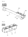
- the PCM 100 includes a protection circuit board (PCB) 110 having a protection circuit formed thereon, the PCB 110 being coupled to a mechanical coupling part (not shown) of a terminal block 200, connecting parts 120 and 130 formed at the bottom of the PCB 110, and the terminal block 200 including a positive temperature coefficient (PTC) element 140 and connectors 210 mounted at the top of the PCB 110.
- PCB protection circuit board
- PTC positive temperature coefficient
- the connectors 210 of the terminal block 200 are mounted at the top of the PCB 110 using surface mounting technology (SMT).
- SMT surface mounting technology
- FIG. 2 is a perspective view typically showing the PCM of FIG. 1 .
- the mechanical coupling part (not shown) includes a fastening protrusion 221 protruding downward from the lower end of the terminal block 200.
- the PCB 110 is provided with a fastening groove 111 formed at a position corresponding to the fastening protrusion 221.
- the protruding height of the fastening protrusion 221 is almost equal to the thickness of the PCB 110.
- a hook 222 protrudes downward from the terminal block 200.
- the hook 222 fixedly fastens the PCB 110 while surrounding the outside of the PCB 110 in a state in which the fastening protrusion 221 is inserted in the fastening groove.
- FIG. 3 is a perspective view showing the terminal block of FIG. 1
- FIG. 4 is a front perspective view showing the top cap housing of FIG. 1 .
- the terminal block 200 is provided at one major surface thereof with a guide lip 230 for mechanical fastening with the top cap housing 200 and hooks 240 disposed at opposite sides of the guide lip 230.
- the top cap housing 300 is provided with a terminal lip 330 and a pair of slit opening 320 corresponding to the guide lip 230 and the hooks 240, respectively.
- the terminal lip 330 is disposed between tapered parts 310.
- the top cap housing 300 is provided with an opening 340 having a size corresponding to the terminal block 200 mounted at the top of the PCB 110 so that the terminal block 200 can be mounted to the top cap housing 300.
- the PCM as shown in FIG. 2 is mounted to a prismatic battery cell (not shown) in a state in which the PCM is electrically connected to the prismatic battery cell, and the top cap housing as shown in FIG. 4 is mounted to the PCM.
- a battery pack is manufactured. Electrical connection between the prismatic battery cell and the PCM is well known in the art to which the present invention pertains, and therefore, a detailed description thereof will be omitted.
Landscapes
- Chemical & Material Sciences (AREA)
- Chemical Kinetics & Catalysis (AREA)
- Electrochemistry (AREA)
- General Chemical & Material Sciences (AREA)
- Engineering & Computer Science (AREA)
- Manufacturing & Machinery (AREA)
- Microelectronics & Electronic Packaging (AREA)
- Battery Mounting, Suspending (AREA)
- Connection Of Batteries Or Terminals (AREA)
Abstract
Description
- The present invention relates to a top cap assembly having a novel structure, and, more particularly, to a top cap assembly mounted to a battery cell having an electrode assembly disposed in a battery case together with an electrolyte in a sealed state, the battery case being provided at an upper end thereof with a first electrode terminal and a second electrode terminal, the top cap assembly including a protection circuit module (PCM) and an electrically insulative top cap housing mounted to the upper end of the battery cell while surrounding an outside of the PCM, wherein the PCM includes a protection circuit board (PCB) having a protection circuit formed thereon, the PCB being coupled to a mechanical coupling part of a terminal block, connecting parts connected to the first electrode terminal and the second electrode terminal, a safety element, and the terminal block mounted to the PCM, the terminal block including connectors.
- As mobile devices have been increasingly developed, and the demand for such mobile devices has increased, the demand for secondary batteries has also sharply increased. Among such secondary batteries is a lithium secondary battery exhibiting high energy density and operating voltage and excellent charge retention and service-life characteristics, which has been widely used as an energy source for various electronic products as well as mobile devices.
- However, various kinds of combustible materials are contained in the lithium secondary battery. As a result, the lithium secondary battery may be heated or explode due to the overcharge of the battery, the overcurrent in the battery, or external physical impact. That is, the safety of the lithium secondary battery is very low. Consequently, safety elements, such as a positive temperature coefficient (PTC) element and a protection circuit module (PCM), to effectively control an abnormal state of the lithium secondary battery, such as the overcharge of the lithium secondary battery or the overcurrent in the lithium secondary battery, are mounted to a battery cell in a state in which the safety elements are connected to the battery cell.
- Generally, a PCM is inserted into a top cap housing and is coupled to the top cap housing by welding or soldering. That is, the PCM is inserted into the top cap housing, in which a connecter is assembled, and is coupled to the top cap housing by welding or soldering so that the PCM is connected to a top cap assembly, and the top cap assembly is coupled to a battery cell. In this way, a battery pack is manufactured.
- When a welding or soldering process is carried out, however, more precise work is required due to a compact structure of the secondary battery with the result that a defect rate may be increased. Also, a battery pack assembly process is complicated due to processes related to soldering, such as soldering, washing, and external appearance inspection of solder.
- In addition, soldering tolerance is unavoidable, and therefore, it is necessary to increase the length of electric components constituting the battery pack with the result that the capacity of the battery cell is reduced.
- Therefore, there is a high necessity for a technology that is capable of stably coupling members mounted to the upper end of a battery cell without soldering and, at the same time, of simplifying an assembly process, thereby minimizing manufacturing cost.
- Therefore, the present invention has been made to solve the above problems, and other technical problems that have yet to be resolved.
- Specifically, it is an object of the present invention to provide a top cap assembly having a terminal block of a novel structure formed at a protection circuit module (PCM).
- It is another object of the present invention to provide a secondary battery pack that can be stably manufactured at minimal cost through a simplified assembly process of a top cap assembly.
- In accordance with one aspect of the present invention, the above and other objects can be accomplished by the provision of a top cap assembly mounted to a battery cell having an electrode assembly of a cathode/separator/anode structure disposed in a battery case together with an electrolyte in a sealed state, the battery case being provided at an upper end thereof with a first electrode terminal and a second electrode terminal, the top cap assembly including a protection circuit module (PCM) and an electrically insulative top cap housing mounted to the upper end of the battery cell while surrounding an outside of the PCM, wherein the PCM includes a protection circuit board (PCB) having a protection circuit formed thereon, the PCB being coupled to a mechanical coupling part of a terminal block, connecting parts connected to the first electrode terminal and the second electrode terminal, a safety element, and the terminal block mounted to the PCM, the terminal block including connectors.
- In the top cap assembly according to the present invention, therefore, the terminal block may be coupled to the PCM through a simple assembly process. As a result, movement between components is minimized, and therefore, the top cap assembly has a very stable structure.
- In a preferred example, the first electrode terminal may be a cathode terminal, and the second electrode terminal may be an anode terminal. For example, a prismatic battery cell is configured to have a structure in which an electrode terminal protruding from the upper end of the prismatic battery cell and a battery case form an anode terminal and a cathode terminal, respectively, and an insulation member, such as a gasket, is disposed between the anode terminal and the cathode terminal. In the structure of such a prismatic battery cell, therefore, the first electrode terminal may be a cathode terminal, which is the upper end of the battery case, and the second electrode terminal may be an anode terminal protruding from the upper end of the battery case.
- The connecting parts may be formed at the bottom of the PCB. For example, the connecting parts may be formed at positions corresponding to the first electrode terminal and the second electrode terminal.
- In another preferred example, the mechanical coupling part may include a fastening protrusion protruding downward from a lower end of the terminal block, and the PCB may be provided with a fastening groove formed at a position corresponding to the fastening protrusion.
- Consequently, the terminal block may be easily mounted to the PCB through coupling between the fastening protrusion and the fastening groove, thereby simplifying an assembly process and improving mechanical stability.
- In the above structure, the terminal block may have at least one hook protruding downward therefrom to fixedly fasten the PCB while surrounding the outside of the PCB in a state in which the fastening protrusion is inserted in the fastening groove in order to secure a more stable coupling state.
- The protruding height of the fastening protrusion may be equal to the thickness ofthe PCB. If the protruding height of the fastening protrusion is too low, the fastening protrusion may not function with the result that coupling force between the fastening protrusion and the fastening groove may be decreased. On the other hand, if the protruding height ofthe fastening protrusion is too high, the volume ofthe top cap assembly is increased, which is not preferable. In consideration of the above matters, therefore, the protruding height ofthe fastening protrusion is properly set. It is preferable for the protruding height of the fastening protrusion to be equal to the thickness of the PCB as described above.
- In a concrete example, the terminal block may be provided at one major surface thereof with a guide lip for mechanical fastening with the top cap housing and hooks disposed at opposite sides of the guide lip.
- Also, the top cap housing may be provided with a terminal lip, which is provided between tapered parts, and a pair of slit opening corresponding to the guide lip and the hooks, respectively. In particular, the protruding terminal lip is formed between the tapered parts. When the top cap housing is mounted to the PCM, therefore, the hooks and the guide lip may be respectively fastened to the terminal lip and the slit openings by force fitting.
- Since coupling between the top cap housing and the terminal block is achieved by force fitting through such a mutual coupling fashion, it is possible to secure a stable coupling state of the top cap assembly.
- In the above structure, the hooks and the guide lip are respectively fastened to the terminal lip and the slit openings when the top cap housing is mounted to the PCM. During mutual coupling, therefore, the movement between the top cap housing, the terminal block, and the PCM is minimized, thereby improving assembly accuracy. Also, a soldering process is omitted, and therefore, the total length of the battery cell is increased, thereby maximizing the capacity of the battery cell.
- Meanwhile, coupling between the safety element of the terminal block and the connectors may be achieved in various manners. For example, the connectors of the terminal block may be mounted to the PCB using surface mounting technology (SMT).
- Using such SMT, it is possible to prevent paste from remaining at the bottom of the PCM during soldering or to prevent the bottom of the PCM from being damaged due to heat during welding. Also, it is possible to achieve accurate and reliable coupling as compared with using conventional welding or soldering. For reference, SMT is widely used to mount surface mount type parts to an electronic board, such as a printed circuit board (PCB).
- In an example, the safety element may be an element, the resistance of which is increased as the temperature of the element is increased. Preferably, the safety element is a positive temperature coefficient (PTC) element. When the temperature of a battery pack is abruptly increased due to internal short circuit, a connection member coupled to the PTC element serves to interrupt current from the upper end of the battery pack. Of course, the safety element is not limited to the PTC element. For example, a bimetal or fuse may be used as the safety element.
- In another example, the top cap housing may be provided with an opening having a size corresponding to the terminal block mounted to the PCB. Consequently, the terminal block can be easily mounted to the top cap housing.
- In accordance with another aspect of the present invention, there is provided a secondary battery pack configured so that the top cap assembly with the above-stated construction according to the present invention is mounted to the upper end of a battery cell having an electrode assembly of a cathode/separator/anode structure disposed in a battery case together with an electrolyte in a sealed state.
- The secondary battery pack may be applied in various manners irrespective of the kind and external appearance of the battery cell. For example, a battery pack including a prismatic lithium secondary battery as the battery cell may be applied.
- In accordance with a further aspect of the present invention, there is provided a method of manufacturing a top cap assembly including (a) coupling a terminal block to the top of a PCB using a mechanical fastening method to manufacture a PCM, and (b) mounting an insulative top cap housing to the PCM.
- In a preferred example, a fastening protrusion is coupled to a fastening groove at step (a), and a guide lip and hooks formed at the inside of the top cap housing are respectively fastened to tapered parts and slit openings formed at the rear of the terminal block at step (b).
- Consequently, it is possible to improve assembly efficiency as compared with a conventional process of manufacturing a top cap assembly, and therefore, it is possible to manufacture a battery pack with improved mechanical strength and stability.
- Of course, some processes of the above manufacturing method may be omitted or other processes may be additionally included in the manufacturing method by those skilled in the art.
- As is apparent from the above description, the top cap assembly according to the present invention can be manufactured to have improved stability using a simplified assembly method including a process of mounting a terminal block of a specific structure to a PCB and a process of mechanically coupling a PCM to a top cap housing.
- The above and other objects, features and other advantages of the present invention will be more clearly understood from the following detailed description taken in conjunction with the accompanying drawings, in which:
-
FIG. 1 is an exploded perspective view showing a top cap assembly according to an embodiment of the present invention; -
FIG. 2 is a perspective view showing a protection circuit module (PCM) ofFIG. 1 ; -
FIG. 3 is a perspective view showing a terminal block ofFIG. 1 ; and -
FIG. 4 is a front perspective view showing a top cap housing ofFIG. 1 . - Now, exemplary embodiments of the present invention will be described in detail with reference to the accompanying drawings. It should be noted, however, that the scope of the present invention is not limited by the illustrated embodiments.
-
FIG. 1 is an exploded perspective view showing atop cap assembly 400 according to an embodiment of the present invention. - Referring to
FIG. 1 , thetop cap assembly 400 includes a protection circuit module (PCM) 100 and an electrically insulativetop cap housing 300 mounted to the upper end of a battery cell (not shown) while surrounding the outside of thePCM 100. - The
PCM 100 includes a protection circuit board (PCB) 110 having a protection circuit formed thereon, thePCB 110 being coupled to a mechanical coupling part (not shown) of aterminal block 200, connectingparts PCB 110, and theterminal block 200 including a positive temperature coefficient (PTC)element 140 andconnectors 210 mounted at the top of thePCB 110. - The
connectors 210 of theterminal block 200 are mounted at the top of thePCB 110 using surface mounting technology (SMT). -
FIG. 2 is a perspective view typically showing the PCM ofFIG. 1 . - Referring to
FIG. 2 together withFIG. 1 , the mechanical coupling part (not shown) includes afastening protrusion 221 protruding downward from the lower end of theterminal block 200. ThePCB 110 is provided with afastening groove 111 formed at a position corresponding to thefastening protrusion 221. - The protruding height of the
fastening protrusion 221 is almost equal to the thickness of thePCB 110. - Also, a
hook 222 protrudes downward from theterminal block 200. Thehook 222 fixedly fastens thePCB 110 while surrounding the outside of thePCB 110 in a state in which thefastening protrusion 221 is inserted in the fastening groove. -
FIG. 3 is a perspective view showing the terminal block ofFIG. 1 , andFIG. 4 is a front perspective view showing the top cap housing ofFIG. 1 . - Referring to these drawings together with
FIGS. 1 and2 , theterminal block 200 is provided at one major surface thereof with aguide lip 230 for mechanical fastening with thetop cap housing 200 and hooks 240 disposed at opposite sides of theguide lip 230. - The
top cap housing 300 is provided with aterminal lip 330 and a pair of slit opening 320 corresponding to theguide lip 230 and thehooks 240, respectively. Theterminal lip 330 is disposed betweentapered parts 310. When thetop cap housing 300 is mounted to thePCM 100, therefore, thehooks 240 and theguide lip 230 are respectively fastened to theterminal lip 330 and theslit openings 320 by force fitting. - Also, the
top cap housing 300 is provided with anopening 340 having a size corresponding to theterminal block 200 mounted at the top of thePCB 110 so that theterminal block 200 can be mounted to thetop cap housing 300. - Although not shown in the drawings, the PCM as shown in
FIG. 2 is mounted to a prismatic battery cell (not shown) in a state in which the PCM is electrically connected to the prismatic battery cell, and the top cap housing as shown inFIG. 4 is mounted to the PCM. As a result, a battery pack is manufactured. Electrical connection between the prismatic battery cell and the PCM is well known in the art to which the present invention pertains, and therefore, a detailed description thereof will be omitted. - Although the exemplary embodiments of the present invention have been disclosed for illustrative purposes, those skilled in the art will appreciate that various modifications, additions and substitutions are possible, without departing from the scope and spirit of the invention as disclosed in the accompanying claims.
Claims (14)
- A top cap assembly mounted to a battery cell having an electrode assembly of a cathode/separator/anode structure disposed in a battery case together with an electrolyte in a sealed state, the battery case being provided at an upper end thereof with a first electrode terminal and a second electrode terminal, the top cap assembly comprising a protection circuit module (PCM) and an electrically insulative top cap housing mounted to the upper end of the battery cell while surrounding an outside of the PCM, wherein the PCM comprises:a protection circuit board (PCB) having a protection circuit formed thereon, the PCB being coupled to a mechanical coupling part of a terminal block;connecting parts connected to the first electrode terminal and the second electrode terminal;a safety element; andthe terminal block mounted to the PCM, the terminal block comprising connectors.
- The top cap assembly according to claim 1, wherein the first electrode terminal is a cathode terminal, and the second electrode terminal is an anode terminal.
- The top cap assembly according to claim 1, wherein the connecting parts are formed at a bottom of the PCB.
- The top cap assembly according to claim 1, wherein the mechanical coupling part comprises a fastening protrusion protruding downward from a lower end of the terminal block, and the PCB is provided with a fastening groove formed at a position corresponding to the fastening protrusion.
- The top cap assembly according to claim 4, wherein the terminal block has at least one hook protruding downward therefrom to fixedly fasten the PCB while surrounding an outside of the PCB in a state in which the fastening protrusion is inserted in the fastening groove.
- The top cap assembly according to claim 4, wherein a protruding height of the fastening protrusion is equal to a thickness of the PCB.
- The top cap assembly according to claim 1, wherein the terminal block is provided at one major surface thereof with a guide lip for mechanical fastening with the top cap housing and hooks disposed at opposite sides of the guide lip.
- The top cap assembly according to claim 7, wherein the top cap housing is provided with a terminal lip, which is provided between tapered p arts, and a pair of slit openings corresponding to the guide lip and the hooks, respectively.
- The top cap assembly according to claim 1, wherein the hooks and the guide lip are fastened to the terminal lip and the slit openings, respectively, whe n the top cap housing is mounted to the PCM.
- The top cap assembly according to claim 1, wherein the connectors of the terminal block are mounted to the PCB using surface mounting technology (SMT).
- The top cap assembly according to claim 1, wherein the safety element is a positive temperature coefficient (PTC) element.
- The top cap assembly according to claim 1, wherein the top cap housing is provided with an opening having a size corresponding to the terminal block mounted to the PCB.
- A secondary battery pack configured so that the top cap assembly according to any one of claims 1 to 12 is mounted to an upper end of a battery cell having an electrode assembly of a cathode/separator/anode structure disposed in a battery case together with an electrolyte in a sealed state.
- The secondary battery pack according to claim 13, wherein the battery cell is a prismatic lithium secondary battery cell.
Applications Claiming Priority (2)
| Application Number | Priority Date | Filing Date | Title |
|---|---|---|---|
| KR1020110109086A KR101371364B1 (en) | 2011-10-25 | 2011-10-25 | Top Cap Assembly Comprising Terminal Block |
| PCT/KR2012/008358 WO2013062256A1 (en) | 2011-10-25 | 2012-10-15 | Top cap assembly having a novel structure |
Publications (3)
| Publication Number | Publication Date |
|---|---|
| EP2741347A1 true EP2741347A1 (en) | 2014-06-11 |
| EP2741347A4 EP2741347A4 (en) | 2014-10-15 |
| EP2741347B1 EP2741347B1 (en) | 2017-03-01 |
Family
ID=48168041
Family Applications (1)
| Application Number | Title | Priority Date | Filing Date |
|---|---|---|---|
| EP12844228.2A Active EP2741347B1 (en) | 2011-10-25 | 2012-10-15 | Top cap assembly |
Country Status (8)
| Country | Link |
|---|---|
| US (1) | US9070911B2 (en) |
| EP (1) | EP2741347B1 (en) |
| JP (1) | JP5851041B2 (en) |
| KR (1) | KR101371364B1 (en) |
| CN (1) | CN103797617B (en) |
| BR (1) | BR112014005737B8 (en) |
| TW (1) | TWI485912B (en) |
| WO (1) | WO2013062256A1 (en) |
Cited By (1)
| Publication number | Priority date | Publication date | Assignee | Title |
|---|---|---|---|---|
| US9887436B2 (en) | 2013-07-09 | 2018-02-06 | Samsung Sdi Co., Ltd. | Battery pack |
Families Citing this family (11)
| Publication number | Priority date | Publication date | Assignee | Title |
|---|---|---|---|---|
| KR101381680B1 (en) * | 2011-10-31 | 2014-04-04 | 주식회사 엘지화학 | Battery Pack Comprising Charging Coil |
| KR101502899B1 (en) * | 2013-07-09 | 2015-03-16 | 삼성에스디아이 주식회사 | Battery Pack |
| KR101619926B1 (en) | 2013-09-27 | 2016-05-12 | 주식회사 엘지화학 | Battery Pack Having PCM Case |
| KR102341400B1 (en) * | 2015-05-06 | 2021-12-20 | 삼성에스디아이 주식회사 | Battery pack |
| KR102459620B1 (en) | 2015-12-01 | 2022-10-27 | 삼성에스디아이 주식회사 | Battery pack |
| KR102221780B1 (en) * | 2017-05-04 | 2021-03-02 | 주식회사 엘지화학 | Battery pack and method for manufcturing the same |
| US10615395B2 (en) | 2017-05-10 | 2020-04-07 | Apple Inc. | Battery cap with cut-out sections |
| JP1667618S (en) * | 2019-07-05 | 2020-09-07 | ||
| JP1667633S (en) * | 2019-07-05 | 2020-09-07 | ||
| JP1667632S (en) * | 2019-07-05 | 2020-09-07 | ||
| JP1667617S (en) * | 2019-07-05 | 2020-09-07 |
Family Cites Families (22)
| Publication number | Priority date | Publication date | Assignee | Title |
|---|---|---|---|---|
| KR100277655B1 (en) | 1998-09-22 | 2001-02-01 | 김순택 | Cap assembly of secondary battery and method for making the same |
| JP3614768B2 (en) * | 2000-10-20 | 2005-01-26 | タイコエレクトロニクスアンプ株式会社 | Battery connector |
| JP2002343315A (en) | 2001-05-10 | 2002-11-29 | Alps Electric Co Ltd | Battery cover unit |
| JP2003142043A (en) | 2001-07-09 | 2003-05-16 | Hitachi Maxell Ltd | Battery |
| CN1922745B (en) | 2004-02-18 | 2010-12-01 | 株式会社Lg化学 | Integral cap assembly including protective circuit board and secondary battery including the same |
| JP4562458B2 (en) * | 2004-08-27 | 2010-10-13 | 三洋電機株式会社 | Pack battery and manufacturing method thereof |
| KR100579377B1 (en) | 2004-10-28 | 2006-05-12 | 삼성에스디아이 주식회사 | Secondary battery |
| WO2006068373A1 (en) | 2004-12-24 | 2006-06-29 | Lg Chem, Ltd. | Secondary battery module |
| JP5323495B2 (en) * | 2005-12-22 | 2013-10-23 | エルジー・ケム・リミテッド | Non-welded battery pack using press-fit rivets |
| KR100861714B1 (en) * | 2005-12-22 | 2008-10-06 | 주식회사 엘지화학 | Battery pack of no welding method using rivet |
| KR100833745B1 (en) | 2007-01-17 | 2008-05-29 | 삼성에스디아이 주식회사 | Secondary battery |
| EP2065952B1 (en) | 2007-11-27 | 2010-02-10 | Swissbatt AG | Battery |
| KR101042750B1 (en) * | 2009-01-09 | 2011-06-20 | 삼성에스디아이 주식회사 | Battery Pack |
| JP5329252B2 (en) * | 2009-02-09 | 2013-10-30 | 三洋電機株式会社 | Pack battery |
| US9331324B2 (en) * | 2009-02-09 | 2016-05-03 | Samsung Sdi Co., Ltd. | Connector assembly and battery pack having the same |
| KR101040975B1 (en) | 2009-02-26 | 2011-06-16 | 주식회사 엘지화학 | New rechargeable battery pack |
| KR101030915B1 (en) | 2009-06-16 | 2011-04-22 | 삼성에스디아이 주식회사 | Battery pack |
| KR20100136107A (en) * | 2009-06-18 | 2010-12-28 | 삼성에스디아이 주식회사 | Battery pack |
| KR101232783B1 (en) * | 2009-08-26 | 2013-02-13 | 주식회사 엘지화학 | secondary battery and manufacturing method thereof |
| US8686689B2 (en) | 2009-11-30 | 2014-04-01 | Samsung Sdi Co., Ltd. | Battery assembly |
| CN102136572B (en) * | 2010-01-26 | 2014-12-31 | 三星Sdi株式会社 | Battery assembly |
| EP2360754B1 (en) * | 2010-01-26 | 2013-11-13 | Samsung SDI Co., Ltd. | Battery assembly |
-
2011
- 2011-10-25 KR KR1020110109086A patent/KR101371364B1/en active Active
-
2012
- 2012-10-15 BR BR112014005737A patent/BR112014005737B8/en active IP Right Grant
- 2012-10-15 US US14/344,383 patent/US9070911B2/en active Active
- 2012-10-15 CN CN201280044593.0A patent/CN103797617B/en active Active
- 2012-10-15 WO PCT/KR2012/008358 patent/WO2013062256A1/en not_active Ceased
- 2012-10-15 EP EP12844228.2A patent/EP2741347B1/en active Active
- 2012-10-15 JP JP2014531742A patent/JP5851041B2/en active Active
- 2012-10-22 TW TW101138908A patent/TWI485912B/en active
Cited By (1)
| Publication number | Priority date | Publication date | Assignee | Title |
|---|---|---|---|---|
| US9887436B2 (en) | 2013-07-09 | 2018-02-06 | Samsung Sdi Co., Ltd. | Battery pack |
Also Published As
| Publication number | Publication date |
|---|---|
| WO2013062256A1 (en) | 2013-05-02 |
| BR112014005737B8 (en) | 2023-03-21 |
| JP5851041B2 (en) | 2016-02-03 |
| CN103797617A (en) | 2014-05-14 |
| EP2741347A4 (en) | 2014-10-15 |
| BR112014005737B1 (en) | 2020-11-03 |
| US9070911B2 (en) | 2015-06-30 |
| CN103797617B (en) | 2016-09-21 |
| TW201342691A (en) | 2013-10-16 |
| KR20130044821A (en) | 2013-05-03 |
| US20150004441A1 (en) | 2015-01-01 |
| BR112014005737A2 (en) | 2017-03-28 |
| EP2741347B1 (en) | 2017-03-01 |
| TWI485912B (en) | 2015-05-21 |
| KR101371364B1 (en) | 2014-03-11 |
| JP2014526791A (en) | 2014-10-06 |
Similar Documents
| Publication | Publication Date | Title |
|---|---|---|
| US9070911B2 (en) | Top cap assembly having terminal block | |
| US8623542B2 (en) | PCM of improved assembling type structure and battery pack employed with the same | |
| JP5450634B2 (en) | Secondary battery pack having a novel structure | |
| EP2218124B1 (en) | Secondary battery pack having pcm assembly and insulating mounting member of novel structure | |
| KR101001315B1 (en) | Excellent energy density secondary battery pack and PCM assembly for it | |
| KR101441524B1 (en) | Secondary Battery of Novel Structure | |
| EP2624336B1 (en) | Secondary battery pack having a novel structure | |
| CN102326278B (en) | Rechargeable battery pack having novel structure | |
| EP2775550B1 (en) | Manufacturing method for battery cells | |
| WO2005055343A1 (en) | Pcm mold and battery having the same | |
| EP2775551B1 (en) | Manufacturing method for battery cells having novel structure |
Legal Events
| Date | Code | Title | Description |
|---|---|---|---|
| PUAI | Public reference made under article 153(3) epc to a published international application that has entered the european phase |
Free format text: ORIGINAL CODE: 0009012 |
|
| 17P | Request for examination filed |
Effective date: 20140304 |
|
| AK | Designated contracting states |
Kind code of ref document: A1 Designated state(s): AL AT BE BG CH CY CZ DE DK EE ES FI FR GB GR HR HU IE IS IT LI LT LU LV MC MK MT NL NO PL PT RO RS SE SI SK SM TR |
|
| A4 | Supplementary search report drawn up and despatched |
Effective date: 20140917 |
|
| RIC1 | Information provided on ipc code assigned before grant |
Ipc: H01M 2/30 20060101ALI20140911BHEP Ipc: H01M 10/42 20060101ALI20140911BHEP Ipc: H01R 12/70 20110101ALI20140911BHEP Ipc: H01M 2/04 20060101AFI20140911BHEP Ipc: H01M 2/26 20060101ALI20140911BHEP |
|
| DAX | Request for extension of the european patent (deleted) | ||
| REG | Reference to a national code |
Ref country code: DE Ref legal event code: R079 Ref document number: 602012029393 Country of ref document: DE Free format text: PREVIOUS MAIN CLASS: H01M0002300000 Ipc: H01M0002040000 |
|
| GRAP | Despatch of communication of intention to grant a patent |
Free format text: ORIGINAL CODE: EPIDOSNIGR1 |
|
| STAA | Information on the status of an ep patent application or granted ep patent |
Free format text: STATUS: GRANT OF PATENT IS INTENDED |
|
| RIC1 | Information provided on ipc code assigned before grant |
Ipc: H01M 10/052 20100101ALI20161101BHEP Ipc: H01M 2/30 20060101ALI20161101BHEP Ipc: H01M 2/26 20060101ALI20161101BHEP Ipc: H01M 10/42 20060101ALI20161101BHEP Ipc: H01M 2/04 20060101AFI20161101BHEP |
|
| INTG | Intention to grant announced |
Effective date: 20161121 |
|
| GRAS | Grant fee paid |
Free format text: ORIGINAL CODE: EPIDOSNIGR3 |
|
| GRAA | (expected) grant |
Free format text: ORIGINAL CODE: 0009210 |
|
| STAA | Information on the status of an ep patent application or granted ep patent |
Free format text: STATUS: THE PATENT HAS BEEN GRANTED |
|
| AK | Designated contracting states |
Kind code of ref document: B1 Designated state(s): AL AT BE BG CH CY CZ DE DK EE ES FI FR GB GR HR HU IE IS IT LI LT LU LV MC MK MT NL NO PL PT RO RS SE SI SK SM TR |
|
| REG | Reference to a national code |
Ref country code: GB Ref legal event code: FG4D |
|
| REG | Reference to a national code |
Ref country code: CH Ref legal event code: EP Ref country code: AT Ref legal event code: REF Ref document number: 872266 Country of ref document: AT Kind code of ref document: T Effective date: 20170315 |
|
| REG | Reference to a national code |
Ref country code: IE Ref legal event code: FG4D |
|
| REG | Reference to a national code |
Ref country code: DE Ref legal event code: R096 Ref document number: 602012029393 Country of ref document: DE |
|
| REG | Reference to a national code |
Ref country code: NL Ref legal event code: MP Effective date: 20170301 |
|
| REG | Reference to a national code |
Ref country code: LT Ref legal event code: MG4D |
|
| REG | Reference to a national code |
Ref country code: AT Ref legal event code: MK05 Ref document number: 872266 Country of ref document: AT Kind code of ref document: T Effective date: 20170301 |
|
| PG25 | Lapsed in a contracting state [announced via postgrant information from national office to epo] |
Ref country code: GR Free format text: LAPSE BECAUSE OF FAILURE TO SUBMIT A TRANSLATION OF THE DESCRIPTION OR TO PAY THE FEE WITHIN THE PRESCRIBED TIME-LIMIT Effective date: 20170602 Ref country code: FI Free format text: LAPSE BECAUSE OF FAILURE TO SUBMIT A TRANSLATION OF THE DESCRIPTION OR TO PAY THE FEE WITHIN THE PRESCRIBED TIME-LIMIT Effective date: 20170301 Ref country code: LT Free format text: LAPSE BECAUSE OF FAILURE TO SUBMIT A TRANSLATION OF THE DESCRIPTION OR TO PAY THE FEE WITHIN THE PRESCRIBED TIME-LIMIT Effective date: 20170301 Ref country code: HR Free format text: LAPSE BECAUSE OF FAILURE TO SUBMIT A TRANSLATION OF THE DESCRIPTION OR TO PAY THE FEE WITHIN THE PRESCRIBED TIME-LIMIT Effective date: 20170301 Ref country code: NO Free format text: LAPSE BECAUSE OF FAILURE TO SUBMIT A TRANSLATION OF THE DESCRIPTION OR TO PAY THE FEE WITHIN THE PRESCRIBED TIME-LIMIT Effective date: 20170601 |
|
| PG25 | Lapsed in a contracting state [announced via postgrant information from national office to epo] |
Ref country code: RS Free format text: LAPSE BECAUSE OF FAILURE TO SUBMIT A TRANSLATION OF THE DESCRIPTION OR TO PAY THE FEE WITHIN THE PRESCRIBED TIME-LIMIT Effective date: 20170301 Ref country code: AT Free format text: LAPSE BECAUSE OF FAILURE TO SUBMIT A TRANSLATION OF THE DESCRIPTION OR TO PAY THE FEE WITHIN THE PRESCRIBED TIME-LIMIT Effective date: 20170301 Ref country code: ES Free format text: LAPSE BECAUSE OF FAILURE TO SUBMIT A TRANSLATION OF THE DESCRIPTION OR TO PAY THE FEE WITHIN THE PRESCRIBED TIME-LIMIT Effective date: 20170301 Ref country code: SE Free format text: LAPSE BECAUSE OF FAILURE TO SUBMIT A TRANSLATION OF THE DESCRIPTION OR TO PAY THE FEE WITHIN THE PRESCRIBED TIME-LIMIT Effective date: 20170301 Ref country code: BG Free format text: LAPSE BECAUSE OF FAILURE TO SUBMIT A TRANSLATION OF THE DESCRIPTION OR TO PAY THE FEE WITHIN THE PRESCRIBED TIME-LIMIT Effective date: 20170601 Ref country code: LV Free format text: LAPSE BECAUSE OF FAILURE TO SUBMIT A TRANSLATION OF THE DESCRIPTION OR TO PAY THE FEE WITHIN THE PRESCRIBED TIME-LIMIT Effective date: 20170301 |
|
| REG | Reference to a national code |
Ref country code: FR Ref legal event code: PLFP Year of fee payment: 6 |
|
| PG25 | Lapsed in a contracting state [announced via postgrant information from national office to epo] |
Ref country code: NL Free format text: LAPSE BECAUSE OF FAILURE TO SUBMIT A TRANSLATION OF THE DESCRIPTION OR TO PAY THE FEE WITHIN THE PRESCRIBED TIME-LIMIT Effective date: 20170301 |
|
| PG25 | Lapsed in a contracting state [announced via postgrant information from national office to epo] |
Ref country code: CZ Free format text: LAPSE BECAUSE OF FAILURE TO SUBMIT A TRANSLATION OF THE DESCRIPTION OR TO PAY THE FEE WITHIN THE PRESCRIBED TIME-LIMIT Effective date: 20170301 Ref country code: EE Free format text: LAPSE BECAUSE OF FAILURE TO SUBMIT A TRANSLATION OF THE DESCRIPTION OR TO PAY THE FEE WITHIN THE PRESCRIBED TIME-LIMIT Effective date: 20170301 Ref country code: IT Free format text: LAPSE BECAUSE OF FAILURE TO SUBMIT A TRANSLATION OF THE DESCRIPTION OR TO PAY THE FEE WITHIN THE PRESCRIBED TIME-LIMIT Effective date: 20170301 Ref country code: SK Free format text: LAPSE BECAUSE OF FAILURE TO SUBMIT A TRANSLATION OF THE DESCRIPTION OR TO PAY THE FEE WITHIN THE PRESCRIBED TIME-LIMIT Effective date: 20170301 Ref country code: RO Free format text: LAPSE BECAUSE OF FAILURE TO SUBMIT A TRANSLATION OF THE DESCRIPTION OR TO PAY THE FEE WITHIN THE PRESCRIBED TIME-LIMIT Effective date: 20170301 |
|
| PG25 | Lapsed in a contracting state [announced via postgrant information from national office to epo] |
Ref country code: IS Free format text: LAPSE BECAUSE OF FAILURE TO SUBMIT A TRANSLATION OF THE DESCRIPTION OR TO PAY THE FEE WITHIN THE PRESCRIBED TIME-LIMIT Effective date: 20170701 Ref country code: SM Free format text: LAPSE BECAUSE OF FAILURE TO SUBMIT A TRANSLATION OF THE DESCRIPTION OR TO PAY THE FEE WITHIN THE PRESCRIBED TIME-LIMIT Effective date: 20170301 Ref country code: PL Free format text: LAPSE BECAUSE OF FAILURE TO SUBMIT A TRANSLATION OF THE DESCRIPTION OR TO PAY THE FEE WITHIN THE PRESCRIBED TIME-LIMIT Effective date: 20170301 Ref country code: PT Free format text: LAPSE BECAUSE OF FAILURE TO SUBMIT A TRANSLATION OF THE DESCRIPTION OR TO PAY THE FEE WITHIN THE PRESCRIBED TIME-LIMIT Effective date: 20170703 |
|
| REG | Reference to a national code |
Ref country code: DE Ref legal event code: R097 Ref document number: 602012029393 Country of ref document: DE |
|
| PLBE | No opposition filed within time limit |
Free format text: ORIGINAL CODE: 0009261 |
|
| STAA | Information on the status of an ep patent application or granted ep patent |
Free format text: STATUS: NO OPPOSITION FILED WITHIN TIME LIMIT |
|
| PG25 | Lapsed in a contracting state [announced via postgrant information from national office to epo] |
Ref country code: DK Free format text: LAPSE BECAUSE OF FAILURE TO SUBMIT A TRANSLATION OF THE DESCRIPTION OR TO PAY THE FEE WITHIN THE PRESCRIBED TIME-LIMIT Effective date: 20170301 |
|
| 26N | No opposition filed |
Effective date: 20171204 |
|
| PG25 | Lapsed in a contracting state [announced via postgrant information from national office to epo] |
Ref country code: SI Free format text: LAPSE BECAUSE OF FAILURE TO SUBMIT A TRANSLATION OF THE DESCRIPTION OR TO PAY THE FEE WITHIN THE PRESCRIBED TIME-LIMIT Effective date: 20170301 |
|
| PG25 | Lapsed in a contracting state [announced via postgrant information from national office to epo] |
Ref country code: MC Free format text: LAPSE BECAUSE OF FAILURE TO SUBMIT A TRANSLATION OF THE DESCRIPTION OR TO PAY THE FEE WITHIN THE PRESCRIBED TIME-LIMIT Effective date: 20170301 |
|
| REG | Reference to a national code |
Ref country code: CH Ref legal event code: PL |
|
| REG | Reference to a national code |
Ref country code: IE Ref legal event code: MM4A |
|
| PG25 | Lapsed in a contracting state [announced via postgrant information from national office to epo] |
Ref country code: LU Free format text: LAPSE BECAUSE OF NON-PAYMENT OF DUE FEES Effective date: 20171015 Ref country code: CH Free format text: LAPSE BECAUSE OF NON-PAYMENT OF DUE FEES Effective date: 20171031 Ref country code: LI Free format text: LAPSE BECAUSE OF NON-PAYMENT OF DUE FEES Effective date: 20171031 |
|
| REG | Reference to a national code |
Ref country code: BE Ref legal event code: MM Effective date: 20171031 |
|
| PG25 | Lapsed in a contracting state [announced via postgrant information from national office to epo] |
Ref country code: BE Free format text: LAPSE BECAUSE OF NON-PAYMENT OF DUE FEES Effective date: 20171031 |
|
| REG | Reference to a national code |
Ref country code: FR Ref legal event code: PLFP Year of fee payment: 7 |
|
| PG25 | Lapsed in a contracting state [announced via postgrant information from national office to epo] |
Ref country code: MT Free format text: LAPSE BECAUSE OF NON-PAYMENT OF DUE FEES Effective date: 20171015 |
|
| PG25 | Lapsed in a contracting state [announced via postgrant information from national office to epo] |
Ref country code: IE Free format text: LAPSE BECAUSE OF NON-PAYMENT OF DUE FEES Effective date: 20171015 |
|
| PG25 | Lapsed in a contracting state [announced via postgrant information from national office to epo] |
Ref country code: HU Free format text: LAPSE BECAUSE OF FAILURE TO SUBMIT A TRANSLATION OF THE DESCRIPTION OR TO PAY THE FEE WITHIN THE PRESCRIBED TIME-LIMIT; INVALID AB INITIO Effective date: 20121015 |
|
| PG25 | Lapsed in a contracting state [announced via postgrant information from national office to epo] |
Ref country code: CY Free format text: LAPSE BECAUSE OF NON-PAYMENT OF DUE FEES Effective date: 20170301 |
|
| PG25 | Lapsed in a contracting state [announced via postgrant information from national office to epo] |
Ref country code: MK Free format text: LAPSE BECAUSE OF FAILURE TO SUBMIT A TRANSLATION OF THE DESCRIPTION OR TO PAY THE FEE WITHIN THE PRESCRIBED TIME-LIMIT Effective date: 20170301 |
|
| PG25 | Lapsed in a contracting state [announced via postgrant information from national office to epo] |
Ref country code: TR Free format text: LAPSE BECAUSE OF FAILURE TO SUBMIT A TRANSLATION OF THE DESCRIPTION OR TO PAY THE FEE WITHIN THE PRESCRIBED TIME-LIMIT Effective date: 20170301 |
|
| PG25 | Lapsed in a contracting state [announced via postgrant information from national office to epo] |
Ref country code: AL Free format text: LAPSE BECAUSE OF FAILURE TO SUBMIT A TRANSLATION OF THE DESCRIPTION OR TO PAY THE FEE WITHIN THE PRESCRIBED TIME-LIMIT Effective date: 20170301 |
|
| REG | Reference to a national code |
Ref country code: DE Ref legal event code: R079 Ref document number: 602012029393 Country of ref document: DE Free format text: PREVIOUS MAIN CLASS: H01M0002040000 Ipc: H01M0050147000 |
|
| P01 | Opt-out of the competence of the unified patent court (upc) registered |
Effective date: 20230512 |
|
| REG | Reference to a national code |
Ref country code: GB Ref legal event code: 732E Free format text: REGISTERED BETWEEN 20230824 AND 20230831 |
|
| REG | Reference to a national code |
Ref country code: DE Ref legal event code: R081 Ref document number: 602012029393 Country of ref document: DE Owner name: LG ENERGY SOLUTION, LTD., KR Free format text: FORMER OWNER: LG CHEM. LTD., SEOUL, KR |
|
| PGFP | Annual fee paid to national office [announced via postgrant information from national office to epo] |
Ref country code: GB Payment date: 20250922 Year of fee payment: 14 |
|
| PGFP | Annual fee paid to national office [announced via postgrant information from national office to epo] |
Ref country code: FR Payment date: 20250925 Year of fee payment: 14 |
|
| PGFP | Annual fee paid to national office [announced via postgrant information from national office to epo] |
Ref country code: DE Payment date: 20250922 Year of fee payment: 14 |