EP2740952A2 - Hydrostatic guide device and machine tool using the hydrostatic guide device - Google Patents
Hydrostatic guide device and machine tool using the hydrostatic guide device Download PDFInfo
- Publication number
- EP2740952A2 EP2740952A2 EP13194985.1A EP13194985A EP2740952A2 EP 2740952 A2 EP2740952 A2 EP 2740952A2 EP 13194985 A EP13194985 A EP 13194985A EP 2740952 A2 EP2740952 A2 EP 2740952A2
- Authority
- EP
- European Patent Office
- Prior art keywords
- faces
- vertical
- hydrostatic
- fluid pressure
- vertical guide
- Prior art date
- Legal status (The legal status is an assumption and is not a legal conclusion. Google has not performed a legal analysis and makes no representation as to the accuracy of the status listed.)
- Granted
Links
Images


Classifications
-
- F—MECHANICAL ENGINEERING; LIGHTING; HEATING; WEAPONS; BLASTING
- F16—ENGINEERING ELEMENTS AND UNITS; GENERAL MEASURES FOR PRODUCING AND MAINTAINING EFFECTIVE FUNCTIONING OF MACHINES OR INSTALLATIONS; THERMAL INSULATION IN GENERAL
- F16C—SHAFTS; FLEXIBLE SHAFTS; ELEMENTS OR CRANKSHAFT MECHANISMS; ROTARY BODIES OTHER THAN GEARING ELEMENTS; BEARINGS
- F16C29/00—Bearings for parts moving only linearly
- F16C29/02—Sliding-contact bearings
- F16C29/025—Hydrostatic or aerostatic
-
- B—PERFORMING OPERATIONS; TRANSPORTING
- B23—MACHINE TOOLS; METAL-WORKING NOT OTHERWISE PROVIDED FOR
- B23Q—DETAILS, COMPONENTS, OR ACCESSORIES FOR MACHINE TOOLS, e.g. ARRANGEMENTS FOR COPYING OR CONTROLLING; MACHINE TOOLS IN GENERAL CHARACTERISED BY THE CONSTRUCTION OF PARTICULAR DETAILS OR COMPONENTS; COMBINATIONS OR ASSOCIATIONS OF METAL-WORKING MACHINES, NOT DIRECTED TO A PARTICULAR RESULT
- B23Q1/00—Members which are comprised in the general build-up of a form of machine, particularly relatively large fixed members
- B23Q1/25—Movable or adjustable work or tool supports
- B23Q1/26—Movable or adjustable work or tool supports characterised by constructional features relating to the co-operation of relatively movable members; Means for preventing relative movement of such members
- B23Q1/38—Movable or adjustable work or tool supports characterised by constructional features relating to the co-operation of relatively movable members; Means for preventing relative movement of such members using fluid bearings or fluid cushion supports
- B23Q1/385—Movable or adjustable work or tool supports characterised by constructional features relating to the co-operation of relatively movable members; Means for preventing relative movement of such members using fluid bearings or fluid cushion supports in which the thickness of the fluid-layer is adjustable
-
- F—MECHANICAL ENGINEERING; LIGHTING; HEATING; WEAPONS; BLASTING
- F16—ENGINEERING ELEMENTS AND UNITS; GENERAL MEASURES FOR PRODUCING AND MAINTAINING EFFECTIVE FUNCTIONING OF MACHINES OR INSTALLATIONS; THERMAL INSULATION IN GENERAL
- F16C—SHAFTS; FLEXIBLE SHAFTS; ELEMENTS OR CRANKSHAFT MECHANISMS; ROTARY BODIES OTHER THAN GEARING ELEMENTS; BEARINGS
- F16C32/00—Bearings not otherwise provided for
- F16C32/06—Bearings not otherwise provided for with moving member supported by a fluid cushion formed, at least to a large extent, otherwise than by movement of the shaft, e.g. hydrostatic air-cushion bearings
- F16C32/0629—Bearings not otherwise provided for with moving member supported by a fluid cushion formed, at least to a large extent, otherwise than by movement of the shaft, e.g. hydrostatic air-cushion bearings supported by a liquid cushion, e.g. oil cushion
- F16C32/064—Bearings not otherwise provided for with moving member supported by a fluid cushion formed, at least to a large extent, otherwise than by movement of the shaft, e.g. hydrostatic air-cushion bearings supported by a liquid cushion, e.g. oil cushion the liquid being supplied under pressure
- F16C32/0644—Details of devices to control the supply of liquids to the bearings
- F16C32/0648—Details of devices to control the supply of liquids to the bearings by sensors or pressure-responsive control devices in or near the bearings
Definitions
- the invention relates to a hydrostatic guide device and a machine tool using the hydrostatic guide device.
- a hydrostatic guide device keeps two members in a non-contact state to reduce friction therebetween. Therefore, hydrostatic pockets, which are recesses, are formed in one of opposed faces of the two members that move relative to each other, and a fluid such as air or oil is spouted from the hydrostatic pockets to form a fluid outflow layer having a predetermined thickness between the two members.
- a fluid such as air or oil is spouted from the hydrostatic pockets to form a fluid outflow layer having a predetermined thickness between the two members.
- the invention provides a hydrostatic guide device configured such that a high degree of stiffness of guidance created between guide faces is stably ensured even if the machining accuracy and the assembling accuracy vary, and provides a machine tool using the hydrostatic guide device.
- a hydrostatic guide device including: a fixed member having a pair of vertical guide faces that face in opposite directions; a movable member having a pair of vertical slide faces that are opposed to the respective vertical guide faces; a fluid supply device; a hydrostatic pocket that is formed in one of the vertical slide faces, the one of the vertical slide faces being opposed to one of the vertical guide faces, the one of the vertical guide faces serving as a reference face, to which a fluid is supplied by the fluid supply device, to which a first fluid pressure based on a dimension of a gap between the one of the vertical guide faces and the one of the vertical slide faces is applied, and that urges the movable member toward the other of the vertical guide faces with a first urging force; and a hydraulic pocket that is formed in other one of the vertical slide faces, the other of the vertical slide faces being opposed to the other one of the vertical guide faces, to which the fluid is supplied by the fluid supply device, to which a second fluid pressure based on a dimension of
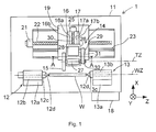
- FIG. 1 illustrates an embodiment of a grinding machine 1 in which a hydrostatic guide device 40 according to the invention is used.
- the grinding machine 1 is a wheel head traverse-type grinding machine.
- FIG. 1 illustrates an example of a plan view of the grinding machine 1
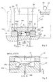
- FIG. 2 is a sectional view taken along the line A-A in FIG. 1 .
- the X-axis, the Y-axis and the Z-axis are orthogonal to each other
- the Y-axis indicates an upward vertical direction
- the Z-axis and the X-axis indicate horizontal directions.
- the Z-axis indicates a direction of axis of rotation of a workpiece
- the X-axis indicates a direction in which a grinding wheel 15 (an example of a tool according to the invention) cuts into a workpiece W (an example of a workpiece according to the invention).
- the grinding machine 1 includes a bed 11, a work head 12 that is secured to the bed 11, and that supports both ends of the workpiece W such that the workpiece W is rotatable, and a foot stock 13. Further, the grinding machine 1 includes a wheel head 14 (an example of a movable member according to the invention) that is movable in both the X-axis direction and the Z-axis direction on the bed 11, the grinding wheel 15 that is rotatably supported to the wheel head 14, the hydrostatic guide device 40 (refer to FIG. 2 ), and a control unit 18 that drives the work head 12 and the grinding wheel 15 and controls the position of the grinding wheel 15 with respect t to the workpiece W.
- a wheel head 14 an example of a movable member according to the invention
- the workpiece W that is rotating about a workpiece rotation axis WZ is ground by the grinding wheel 15.
- the grinding wheel 15 is formed in a disc shape.
- the grinding wheel 15 is rotated about a grinding wheel rotation axis TZ, and is arranged so as to be movable in both the Z-axis direction and the X-axis direction relative to the workpiece W.
- the workpiece rotation axis WZ and the grinding wheel rotation axis TZ are both in parallel with the Z-axis.
- the work head 12 includes a base 12a, a spindle housing 12b and a main spindle 12c.
- the base 12a is arranged on the bed 11.
- the spindle housing 12b is configured so as to be able to reciprocate in the Z-axis direction relative to the base 12a.
- the main spindle 12c is supported so as to be rotatable about the workpiece rotation axis WZ in the spindle housing 12b.
- a centering member 12d is provided at one end of the main spindle 12c.
- a drive motor (not illustrated) is provided for the main spindle 12c.
- the control unit 18 controls the rotation of the main spindle 12c about the workpiece rotation axis WZ, which passes through the distal end of the centering member 12d, to a given angle, at a given angular velocity.
- the foot stock 13 includes a base 13a, a tailstock spindle housing 13b, a tailstock spindle housing 13b, and a tailstock spindle 13c.
- the base 13a is arranged on the bed 11.
- the tailstock spindle housing 13b is configured so as to be movable in the Z-axis direction relative to the base 13a.
- the tailstock spindle 13c is supported so as to be rotatable or non-rotatable about the workpiece rotation axis WZ in the tailstock spindle housing 13b, and is arranged so as to coaxial with the main spindle 12c.
- the workpiece W is supported at its both ends (or at portions near the both ends) by the work head 12 including the centering member 12d and the foot stock 13 including a centering member 13d (chucks may be used instead of the centering members).
- a traverse base 19 (an example of a fixed member according to the invention) is arranged on the bed 11.
- the traverse base 19 is positioned, under control, at a given position in the Z-axis direction along a V-shape guide 23 in accordance with a rotation angle of a ball screw 22 that is controlled by a Z-axis drive motor 21.
- the control unit 18 detects a signal from position detecting means such an encoder (not illustrated) and outputs a control signal to the Z-axis drive motor 21 to position the traverse base 19 in the Z-axis direction.
- the wheel head 14 (an example of a movable member according to the invention) that advances or retracts the grinding wheel 15 is arranged on the traverse base 19.
- the wheel head 14 is positioned, under control, at a given position in the X-axis direction, along guides 16, 17 that are provided integrally with the upper face of the traverse base 19, in accordance with a rotation angle of the ball screw 30 that is controlled by an X-axial drive motor 25.
- the control unit 18 detects a signal from position detecting means and outputs a control signal to the X-axial drive motor 25 to position the wheel head 14 (movable member) at a position in the X-axis direction.
- the grinding wheel rotation axis TZ and the workpiece rotation axis WZ are positioned on the same horizontal plane.
- the grinding wheel 15 is brought closer to the workpiece W, and a machining point is set to a point on the grinding wheel 15 side, at which the grinding wheel 15 comes into contact with the workpiece W.
- a coolant nozzle (not illustrated) that supplies a coolant to the vicinity of the machining point is provided in the grinding machine 1.
- Dressing means (not illustrated) for dressing the grinding wheel 15 is attached to the spindle housing 12b in the grinding machine 1 illustrated in an example in FIG. 1 and FIG. 2 .
- the wheel head (movable member) 14 includes a slide table 26, the grinding wheel 15, a grind wheel bearing 27, a grinding wheel drive motor (servo-motor) 28, the X-axial drive motor 25 and the like.
- the rotative power is transmitted from the grinding wheel drive motor 28 to the grinding wheel 15 via a drive pulley 29, a belt 31 and a driven pulley 32.
- the wheel head 14 is advanced or retracted by the grinding wheel drive motor 28 and the ball screw 30.
- a linear motor may be used.
- a driving mechanism that advances or retracts the wheel head 14 is not particularly limited.
- the hydrostatic guide device 40 includes the traverse base (fixed member) 19, the wheel head 14 (movable member), a hydraulic pump 33 (an example of a fluid supply device according to the invention), variable orifices 24 (an example of orifices according to the invention), a hydrostatic pocket 34 that is connected to the hydraulic pump 33 through the variable orifice 24, and a hydraulic pocket 35 that is directly connected to the hydraulic pump 33.
- the hydraulic pump 33 draws a fluid such as oil up from a reservior 37 and then discharges the fluid at a pressure P (discharge pressure).
- the hydraulic pump 33 is controlled by the control unit 18 so as to discharge the fluid always at a constant pressure.
- the discharged fluid is circulated in the hydrostatic guide device 40, and is then returned into the reservior 37 by recovery means (not illustrated).
- the traverse base 19 includes a pair of the guides 16, 17 that are mounted on the upper face of the traverse base 19 and that moves the wheel head 14 in the X-axis direction.
- the guides 16, 17 are separated from each other in the Z-axis direction, and are extended in the X-axis direction by an equal length.
- the guide 16 is arranged so as to be closer to the grinding wheel 15 (an example of a tool according to the invention) than the guide 17.
- the guides 16, 17 respectively have opposed faces, that is, a pair of vertical guide faces 16a, 17a that faces in opposite directions.
- the vertical guide face 16a may function as one of vertical guide faces according to the invention, and serves as a reference face.
- the vertical guide face 17a may function as the other one of the vertical guide faces according to the invention.
- a horizontal guide face 16b that is orthogonal to the vertical guide face 16a is formed on the upper face of the guide 16.
- a horizontal guide face 17b that is orthogonal to the vertical guide face 17a is formed on the upper face of the guide 17.
- the horizontal guide face 16b and the horizontal guide face 17b are formed so as to have the same height.
- the horizontal guide face 16b and the horizontal guide face 17b may have different heights. Note that the horizontal guide face 16b and the horizontal guide face 17b are located at positions outside the vertical guide faces 16a, 17a, respectively.
- a pair of vertical slide faces 14a1, 14a2 is formed on the lower face of the slide table 26 of the wheel head 14.
- the vertical slide faces 14a1, 14a2 are opposed to the vertical guide faces 16a, 17a of the guides 16, 17 of the traverse base 19, when the wheel head 14 is arranged on the traverse base 19.
- the vertical slide face 14a1 may function as one of vertical slide faces according to the invention
- the vertical slide face 14a2 may function as the other one of the vertical slide faces according to the invention.
- a pair of horizontal slide faces 14b1, 14b2 that are opposed to the horizontal guide faces 16b, 17b of the guides 16, 17 are formed on the lower face of the slide table 26. Because the wheel head 14 is just arranged on the traverse base 19, only a load corresponding to the weight of the wheel head 14 is exerted on the horizontal guide faces 16b, 17b.
- the hydrostatic pocket 34 which is a recess, is formed in the vertical slide face 14a1 that is opposed to the vertical guide face 16a that serves as the reference face.
- the hydrostatic pocket 34 is connected to the hydraulic pump 33 through the variable orifice 24 as described above.
- the variable orifice 24 is a variable orifice of a diaphragm type as illustrated in FIG. 3 as an example.
- the variable orifice 24 may be a variable orifice of a spool type or may be a variable orifice of another type, instead of the variable orifice of a diaphragm type.
- the diaphragm-type variable orifice 24 includes an upper housing 41, a lower housing 42 and a diaphragm 43.
- the variable orifice 24 discharges a fluid that is supplied from an inlet port 24a, into the hydrostatic pocket 34 from an outlet port 24b through an annular portion R that serves as an orifice.
- the fluid is directly supplied to the inlet port 24a from the hydraulic pump 33.
- the pressure of the fluid in the hydrostatic pocket 34 is increased, the pressure of the fluid in the outlet port 24b that is communicated with the hydrostatic pocket 34 and the pressure of the fluid in a fluid reservoir 24c are increased.
- the diaphragm 43 is pushed up, and accordingly, the area of the annular portion R is increased, and accordingly, the flow rate is increased.
- the hydraulic pocket 35 is formed in the vertical slide face 14a2 that is opposed to the vertical guide face 17a. As described above, the hydraulic pocket 35 is directly connected to the hydraulic pump 33. That is, the discharge pressure P of the hydraulic pump 33 is directly applied to the hydraulic pocket 35 as it is, and serves as a second fluid pressure P2.
- the hydraulic pocket 35 is arranged such that the center position of the hydraulic pocket 35 in the vertical direction is set to be above the center position of the hydrostatic pocket 34 in the vertical direction.
- the center position of the hydraulic pocket 35 and the center position of the hydrostatic pocket 34 coincide with the heights of the gravitational load centers of the second urging force F2 and the first urging force F1 that are generated by the hydraulic pocket 35 and the hydrostatic pocket 34 upon reception of the second fluid pressure P2 and the first fluid pressure P1, respectively.
- Horizontal hydrostatic pockets 36, 36 which are recesses, are respectively formed in the horizontal slide faces 14b1, 14b2.
- the horizontal hydrostatic pockets 36, 36 are connected to the hydraulic pump 33 through the variable orifices 24.
- the horizontal slide faces 14b1, 14b2 contact and press respectively the horizontal guide faces 16b, 17b due to the weight of the wheel head 14.
- the hydraulic pump 33 When the hydraulic pump 33 is operated, the fluid is supplied into the horizontal hydrostatic pockets 36, 36 from the hydraulic pump 33 through the variable orifices 24.
- the first fluid pressure P1 is supplied into the hydrostatic pocket 34 through the variable orifice 24, and the second fluid pressure P2 that is nearly equal to the discharge pressure P of the hydraulic pump 33 is supplied into the hydraulic pocket 35. Further, the wheel head 14 is moved in one of directions along the X-axis, and then, falls into a horizontally balanced state in which the first urging force F1 (P1 ⁇ S1) is equal to the second urging force F2 (P2 ⁇ S2).
- the first fluid pressure P1 the second fluid pressure P2 ⁇ (S2 / S1).
- the above state will be described in detail with reference to a graph illustrated in FIG. 4 .
- the graph in FIG. 4 illustrates the characteristics of the first fluid pressure P1 and the second fluid pressure P2 in a case where a region on the right side of 0 in the abscissa axis represents the fluid pressure and the ordinate axis represents the gap L.
- the first fluid pressure P1 supplied into the hydrostatic pocket 34 greatly varies depending upon a variation in the gap L
- the variation in the second fluid pressure P2 which is supplied into the hydraulic pocket 35, due to a variation in the gap L is small.
- the variation of the second fluid pressure P2 with respect to a variation in the gap L2 between the vertical guide face 17a and the vertical slide face 14a2 is smaller than the variation of the first fluid pressure P1 with respect to a variation in the gap L1 between the vertical guide face 16a and the vertical slide face 14a1.
- a region on the left side of 0 in the abscissa axis represents the guidance stiffness T, the relationship between the gap L and the guidance stiffness T is illustrated.
- the guidance stiffness T increases in the leftward direction.
- the gap L is set so as to fall in a region II where the guidance stiffness T is higher than that in the other regions.
- the gap L in the region II is set to, for example, L1a.
- the first fluid pressure P1 is P1a on the basis of the graph in FIG. 4 .
- the first fluid pressure P1a with respect to the gap L1 a as the set value is assumed to be, for example, 1/2 of the second fluid pressure P2a (nearly equal to the discharge pressure P) at this time.
- the area S1 of the hydrostatic pocket 34 that generates the first urging force F1 is set to half the area S2 of the hydraulic pocket 35.
- the first urging force F1 is balanced with the second urging force F2 generated by the second fluid pressure P2 that is nearly equal to the discharge pressure P of the hydraulic pump 33, and accordingly, the gap L1a is obtained by the first fluid pressure P1a.
- the gap L2 is automatically determined on the basis of the dimensions of the slide table 26, the traverse base 19, the guides 16, 17 and the gap L1a.
- the discharge pressure P of the hydraulic pump 33 is determined on the basis of various constraint conditions.
- the gap L1a for obtaining a desired stiffness is set, and the area S2 of the hydraulic pocket 35 and the area S1 of the hydrostatic pocket 34 with respect to the area S2 are determined such that the first urging force F1 and the second urging force F2 are balanced with each other at the time when the gap La is obtained.
- the set value is a single value that is the gap L1a.
- the invention is not limited to this, and the set value may be set within a certain range in view of a variation in the second urging force F2 based on a variation in the discharge pressure P of the hydraulic pump 33.
- the center position of the hydraulic pocket 35 in the vertical direction is set to be above the center position of the hydrostatic pocket 34 in the vertical direction.
- a rotational moment M is generated at the wheel head 14.
- the thus generated rotational moment M presses the horizontal slide face 14b1 of the slide table 26 of the wheel head 14, against the horizontal guide face 16b on the vertical guide face 16a side.
- the vertical guide face 16a serves as the reference face.
- the hydrostatic guide device 40 is also actuated, and accordingly, the fluid is discharged from the hydraulic pump 33 at the discharge pressure P.
- the thus discharge fluid is supplied into the hydrostatic pocket 34 and the hydraulic pocket 35.
- the first fluid pressure P1 based on the gap L1b is supplied into the hydrostatic pocket 34 on the reference face side, under the action of the variable orifice 24.
- the second fluid pressure P2 that is substantially equal to the discharge pressure P is supplied into the hydraulic pocket 35 (refer to the graph in FIG. 4 ).
- the first urging force F1 and the second urging force F2 cannot be balanced with each other unless the first fluid pressure P1 has the magnitude of 1/2 of the second fluid pressure P2 on the basis of the area ratio between S1 and S2 (1/2).
- the wheel head 14 is urged and moved by the second urging force F2 toward the vertical guide face 16a (reference face) in the Z-axis direction.
- the gap L1b is gradually decreased, and the first fluid pressure P1 eventually becomes the first fluid pressure P1a.
- the first urging force F1 due to the first fluid pressure P1 and the second urging force F2 due to the second fluid pressure P2 are balanced with each other, and, as a result, the gap L1 on the reference face side becomes the gap L1a that is the set value.
- the assembled state of the traverse base 19 and the wheel head 14 that are roughly assembled together is modified into a desired assembled state.
- the guidance stiffness of the reference face located on the grinding wheel 15 side is brought to a value that is set in advance.
- the rotational moment M is generated at the wheel head 14, and accordingly, the horizontal slide face 14b1 is pressed against the horizontal guide face 16b, as described above.
- the horizontal hydrostatic pockets 36, 36 are formed in the horizontal slide faces 14b1, 14b2 of the wheel head 14.
- the horizontal hydrostatic pockets 36, 36 may be omitted, and instead, there may be used a slide-type guide in which the horizontal slide faces 14b1, 14b2 and the horizontal guide faces 16b, 17b are brought into contact with each other and slid relative to each other.
- the guides 16, 17 may be supported from below via hydrostatic pockets 46, 47.
- the tool is arranged on the movable member, and the tool is the grinding wheel 15 of the wheel head 14.
- the invention is not limited to this configuration, and a workpiece may be arranged on the movable member. In this case, the workpiece may be arranged closer to the reference face side than the vertical guide face 17a. With this configuration as well, a satisfactory degree of accuracy of machining the workpiece can be obtained.
- the gap L1 between the vertical guide face 16a serving as the reference face and the vertical slide face 14a1 can be brought to a value within a predetermined range when the first urging force F1 and the second urging force F2 are balanced with each other in the horizontal direction. Accordingly, even if a variation in the gap L1 between the reference face (vertical guide face 16a) and the vertical slide face 14a1 occurs during the assembly of the hydrostatic guide device 40, the gap L1 between reference face (vertical guide face 16a) and the vertical slide face 14a1 can be brought into a value within a desired range by actuating the hydrostatic guide device 40. Thus, it is possible to obtain a satisfactory guidance stiffness. Further, because the assembly can be roughly made, the man-hours required for the assembly can be reduced.
- the area S1 of the hydrostatic pocket 34 is set to be larger than the area S2 of the hydraulic pocket 35. Therefore, in the state in which the wheel head 14 (movable member) is moved in the Z-axis direction and the first urging force F1 and the second urging force F2 are balanced with each other, the first fluid pressure P1 may be set to a value smaller than the second fluid pressure P2 on the basis of the area ratio. Accordingly, by appropriately setting the area ratio between the area S1 of the hydrostatic pocket 34 and the area S2 of the hydraulic pocket 35, the first fluid pressure P1 can be set to a value at which the fluid can be easily supplied. Thus, it is possible to obtain the gap L1 having a desired value at which a high degree the guidance stiffness is obtained.
- the fluid having the discharge pressure P is directly supplied as the fluid having the second fluid pressure P2 into the hydraulic pocket 35 from the hydraulic pump 33 (fluid supply device).
- the second fluid pressure P2 is a constant pressure
- the discharge pressure P from the hydraulic pump 33 can be decreased just by providing the variable orifice 24 that has a simple structure in the supply passage from the hydraulic pump 33.
- the first fluid pressure P1 based on the area ratio (S2/S1).
- the vertical center position of the hydrostatic pocket 34 that is opposed to the vertical guide face 16a serving as the reference face is located below the vertical center position of the hydraulic pocket 35.
- the rotational moment M is created at the wheel head 14.
- the thus created rotational moment M presses the horizontal slide face 14b1 of the wheel head 14 on the reference face side against the horizontal guide face 16b that is opposed to the horizontal slide face 14b1.
- the wheel head 14 (movable member) arranged on the traverse base 19 (fixed member) only by its weight, can be firmly held on the traverse base 19.
- the wheel head 14 can restrain the wheel head 14 from moving up from the traverse base 19 due to a reaction force that is exerted by the workpiece W and that is created at the machining point when the grinding wheel 15 grinds the workpiece W after the wheel head 14 is advanced in the X-axis direction.
- the hydrostatic guide device 40 according to the invention is applied to the grinding machine 1 (an example of a machine tool according to the invention), the possibility that the machining point of the grinding wheel 15 that is provided to the wheel head 14 (movable member) on the reference face side, is low. Thus it is possible to provide the grinding machine 1 capable of machining a workpiece with a high degree of accuracy.
- the hydraulic pocket 35 is arranged such that the vertical center position of the hydraulic pocket 35 is located above the vertical center position of the hydrostatic pocket 34 in order to create the rotational moment M.
- the invention is not limited to this configuration, and the vertical center position of the hydraulic pocket 35 and the vertical center position of the hydrostatic pocket 34 may be located at the same level of height. With this configuration as well, it is possible to obtain the effect that the position of the wheel head 14 is modified in the Z-axis direction (horizontal direction).
- a second modified example will be described with reference to FIG. 6 .
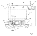
- a vertical guide face 16aa serving as the reference face is formed so as to be tilted so that the wheel head 14 is urged downward by a force component Ya of the first urging force F1.
- a vertical slide face 14aa opposed to the vertical guide face 16aa is tilted so as to correspond to the vertical guide face 16aa.
- the horizontal slide face 14b1 of the wheel head 14 (movable member) that is mounted on the traverse base 19 only by its weight is pressed onto the horizontal guide face 16b opposed to the horizontal slide face 14b1 in order to enhance the vertical guidance stiffness T on the reference face side.
- the third modified example differs from the first modified example in that, a vertical guide face 17aa is formed so as to be tilted so that the wheel head 14 is urged downward by the force component Yb of the second urging force F2 in addition to the force component Ya of the first urging force F1. Further, the vertical slide face 14bb opposed to the vertical guide face 17aa is formed so as to be tilted so as to correspond to the vertical guide face 17aa. Thus, in the wheel head 14, the horizontal slide faces 14b1, 14b2 are pressed against the horizontal guide faces 16b, 17b. As a result, it is possible to enhance the guidance stiffness T, thereby restraining the wheel head 14 from moving up.
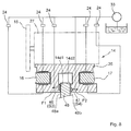
- the fourth modified example differs from the third modified example in that a guide 48 is additionally provided.
- the guide 48 is secured onto the traverse base 19.
- the guide 48 has vertical guide faces 48a, 48b formed on its left and right side.
- the slide table 26 of the wheel head 14 (movable member) has vertical slide faces 14d1, 14d2 that are formed respectively on the faces that are opposed to the vertical guide faces 48a, 48b.
- a hydrostatic pocket 46 having an area S3 is formed in the vertical slide face 14d1, and a hydraulic pocket 47 having an area S4 is formed in the vertical slide face 14d2.
- the hydrostatic pocket 46 is connected to the hydraulic pump 33 through the variable office 24.
- the hydraulic pocket 47 is connected directly to the hydraulic pump 33.
- the fourth modified example has the same configuration and the same operation as those of the above-described embodiment, except the configuration as stated just above. With the fourth modified example as well, advantageous effects similar to those obtained by the above-described embodiment can be obtained.
- the area S1 (S3) of the hydrostatic pocket 34, 46 and the area S2 (S4) of the hydraulic pocket 35, 47 are set such that the following relationship is satisfied; S1 (S3) > S2 (S4).
- a regulator is interposed between the hydraulic pocket 35, 47 and the hydraulic pump 33 to control the second fluid pressure P2 that is supplied into the hydraulic pocket 35, 47 such that the second fluid pressure P2 is equal to the first fluid pressure P2.
- variable orifice 24 is provided between the hydrostatic pocket 34 and the hydraulic pump 33.
- the invention is not limited to this configuration. Instead of the variable orifice 24, a fixed orifice may be used. With this configuration as well, advantageous effects similar to those obtained by the above-described embodiment can be expected.
- the hydrostatic guide device 40 is applied to the grinding machine.
- the invention is not limited to this, and the hydrostatic guide device 40 may be applied to any machine tools other than a grinding machine.
- the hydrostatic guide device 40 may be applied to, for example, a lathe turning machine, a milling machine, a drilling machine, a machining center or the like, and a movable member, which supports a tool for the machine tool or a workpiece in a cantilever-like manner, may be supported on a fixed member via the hydrostatic guide device 40.
- the tool or the workpiece may be arranged on the reference face side.
- the assembly of the movable member can be performed within a short time. Further, the workpiece can be machined with a high degree of accuracy by operating the machine tool.
- a hydrostatic guide device includes: a fixed member (19) having vertical guide faces (16a, 17a); a movable member (14) having vertical slide faces (14a1, 14a2); a fluid supply device (33); a hydrostatic pocket (34) to which a first fluid pressure (P1) based on a dimension of a gap (L1) is applied, and that urges the movable member with a first urging force (F1); and a hydraulic pocket (35) to which a second fluid pressure (P2) based on a dimension of a gap (L2) is applied, and that urges the movable member with a second urging force (F2).
- a variation of the second fluid pressure (P2) is smaller than a variation of the first fluid pressure (P1).
Landscapes
- Engineering & Computer Science (AREA)
- General Engineering & Computer Science (AREA)
- Mechanical Engineering (AREA)
- Magnetic Bearings And Hydrostatic Bearings (AREA)
- Machine Tool Units (AREA)
- Bearings For Parts Moving Linearly (AREA)
Abstract
Description
- The invention relates to a hydrostatic guide device and a machine tool using the hydrostatic guide device. 2. Discussion of Background
- A hydrostatic guide device keeps two members in a non-contact state to reduce friction therebetween. Therefore, hydrostatic pockets, which are recesses, are formed in one of opposed faces of the two members that move relative to each other, and a fluid such as air or oil is spouted from the hydrostatic pockets to form a fluid outflow layer having a predetermined thickness between the two members. Thus, the sliding between the two members is improved and the stiffness of guidance created between guide faces is enhanced. According to a conventional technique described in, for example,
Japanese Patent Application Publication No. 6-735 JP 6-735 A - However, with the conventional technique described in
JP 6-735 A - The invention provides a hydrostatic guide device configured such that a high degree of stiffness of guidance created between guide faces is stably ensured even if the machining accuracy and the assembling accuracy vary, and provides a machine tool using the hydrostatic guide device.
- According to a feature of an example of the invention, there is provided a hydrostatic guide device including: a fixed member having a pair of vertical guide faces that face in opposite directions; a movable member having a pair of vertical slide faces that are opposed to the respective vertical guide faces; a fluid supply device; a hydrostatic pocket that is formed in one of the vertical slide faces, the one of the vertical slide faces being opposed to one of the vertical guide faces, the one of the vertical guide faces serving as a reference face, to which a fluid is supplied by the fluid supply device, to which a first fluid pressure based on a dimension of a gap between the one of the vertical guide faces and the one of the vertical slide faces is applied, and that urges the movable member toward the other of the vertical guide faces with a first urging force; and a hydraulic pocket that is formed in other one of the vertical slide faces, the other of the vertical slide faces being opposed to the other one of the vertical guide faces, to which the fluid is supplied by the fluid supply device, to which a second fluid pressure based on a dimension of a gap between the other one of the vertical guide faces and the other one of the vertical slide faces is applied, and that urges the movable member toward the one of the vertical guide faces with a second urging force, wherein a variation of the second fluid pressure with respect to a variation of the gap between the other one of the vertical guide faces and the other one of the vertical slide face is smaller than a variation of the first fluid pressure with respect to a variation of the gap between the one of the vertical guide faces and the one of the vertical slide faces, and when the first urging force and the second urging force are balanced with each other in a horizontal direction, the gap between the one of the vertical guide faces, the one of the vertical guide faces serving as the reference face, and the one of the vertical slide faces becomes a set value.
- The foregoing and further objects, features and advantages of the invention will become apparent from the following description of example embodiments with reference to the accompanying drawings, wherein like numerals are used to represent like elements and wherein:
-
FIG. 1 is a plan view illustrating an embodiment of a grinding machine in which a hydrostatic guide device according to the invention is used; -
FIG. 2 is a sectional view taken along the line A-A inFIG. 1 ; -
FIG. 3 is a sectional view illustrating the configuration of a variable orifice; -
FIG. 4 is a graph illustrating the relationship between the fluid pressure and a gap in the hydrostatic guide device, and the relationship between the gap and the guidance stiffness; -
FIG. 5 is a view illustrating a first modified example; -
FIG. 6 is a view illustrating a second modified example; -
FIG. 7 is a view illustrating a third modified example; and -
FIG. 8 is a view illustrating a fourth modified example. - Hereinafter, embodiments of the invention will be described with reference to the accompanying drawings.
-
FIG. 1 illustrates an embodiment of agrinding machine 1 in which ahydrostatic guide device 40 according to the invention is used. Thegrinding machine 1 is a wheel head traverse-type grinding machine.FIG. 1 illustrates an example of a plan view of thegrinding machine 1, andFIG. 2 is a sectional view taken along the line A-A inFIG. 1 . In all the drawings in which an X-axis, a Y-axis, and a Z-axis are drawn, the X-axis, the Y-axis and the Z-axis are orthogonal to each other, the Y-axis indicates an upward vertical direction, and the Z-axis and the X-axis indicate horizontal directions. The Z-axis indicates a direction of axis of rotation of a workpiece, and the X-axis indicates a direction in which a grinding wheel 15 (an example of a tool according to the invention) cuts into a workpiece W (an example of a workpiece according to the invention). - As illustrated in
FIG. 1 , thegrinding machine 1 includes abed 11, awork head 12 that is secured to thebed 11, and that supports both ends of the workpiece W such that the workpiece W is rotatable, and afoot stock 13. Further, thegrinding machine 1 includes a wheel head 14 (an example of a movable member according to the invention) that is movable in both the X-axis direction and the Z-axis direction on thebed 11, thegrinding wheel 15 that is rotatably supported to thewheel head 14, the hydrostatic guide device 40 (refer toFIG. 2 ), and acontrol unit 18 that drives thework head 12 and thegrinding wheel 15 and controls the position of thegrinding wheel 15 with respect t to the workpiece W. - In the
grinding machine 1, the workpiece W that is rotating about a workpiece rotation axis WZ is ground by the grindingwheel 15. The grindingwheel 15 is formed in a disc shape. The grindingwheel 15 is rotated about a grinding wheel rotation axis TZ, and is arranged so as to be movable in both the Z-axis direction and the X-axis direction relative to the workpiece W. The workpiece rotation axis WZ and the grinding wheel rotation axis TZ are both in parallel with the Z-axis. - As illustrated in
FIG. 1 andFIG. 2 , thework head 12 includes abase 12a, aspindle housing 12b and amain spindle 12c. Thebase 12a is arranged on thebed 11. Thespindle housing 12b is configured so as to be able to reciprocate in the Z-axis direction relative to thebase 12a. Themain spindle 12c is supported so as to be rotatable about the workpiece rotation axis WZ in thespindle housing 12b. A centeringmember 12d is provided at one end of themain spindle 12c. A drive motor (not illustrated) is provided for themain spindle 12c. Thecontrol unit 18 controls the rotation of themain spindle 12c about the workpiece rotation axis WZ, which passes through the distal end of the centeringmember 12d, to a given angle, at a given angular velocity. - The
foot stock 13 includes abase 13a, atailstock spindle housing 13b, atailstock spindle housing 13b, and a tailstock spindle 13c. Thebase 13a is arranged on thebed 11. Thetailstock spindle housing 13b is configured so as to be movable in the Z-axis direction relative to thebase 13a. The tailstock spindle 13c is supported so as to be rotatable or non-rotatable about the workpiece rotation axis WZ in thetailstock spindle housing 13b, and is arranged so as to coaxial with themain spindle 12c. The workpiece W is supported at its both ends (or at portions near the both ends) by thework head 12 including the centeringmember 12d and thefoot stock 13 including a centering member 13d (chucks may be used instead of the centering members). - A traverse base 19 (an example of a fixed member according to the invention) is arranged on the
bed 11. Thetraverse base 19 is positioned, under control, at a given position in the Z-axis direction along a V-shape guide 23 in accordance with a rotation angle of aball screw 22 that is controlled by a Z-axis drive motor 21. Thecontrol unit 18 detects a signal from position detecting means such an encoder (not illustrated) and outputs a control signal to the Z-axis drive motor 21 to position thetraverse base 19 in the Z-axis direction. - The wheel head 14 (an example of a movable member according to the invention) that advances or retracts the grinding
wheel 15 is arranged on thetraverse base 19. Thewheel head 14 is positioned, under control, at a given position in the X-axis direction, alongguides traverse base 19, in accordance with a rotation angle of theball screw 30 that is controlled by anX-axial drive motor 25. Thecontrol unit 18 detects a signal from position detecting means and outputs a control signal to theX-axial drive motor 25 to position the wheel head 14 (movable member) at a position in the X-axis direction. - As illustrated in
FIG. 2 , for example, the grinding wheel rotation axis TZ and the workpiece rotation axis WZ are positioned on the same horizontal plane. In this state, thegrinding wheel 15 is brought closer to the workpiece W, and a machining point is set to a point on the grindingwheel 15 side, at which the grindingwheel 15 comes into contact with the workpiece W. A coolant nozzle (not illustrated) that supplies a coolant to the vicinity of the machining point is provided in thegrinding machine 1. Dressing means (not illustrated) for dressing the grindingwheel 15 is attached to thespindle housing 12b in thegrinding machine 1 illustrated in an example inFIG. 1 andFIG. 2 . - As illustrated in
FIG. 1 andFIG. 2 , the wheel head (movable member) 14 includes a slide table 26, the grindingwheel 15, a grind wheel bearing 27, a grinding wheel drive motor (servo-motor) 28, theX-axial drive motor 25 and the like. The rotative power is transmitted from the grinding wheel drive motor 28 to the grindingwheel 15 via adrive pulley 29, abelt 31 and a driven pulley 32. In the present embodiment, thewheel head 14 is advanced or retracted by the grinding wheel drive motor 28 and theball screw 30. Alternatively, a linear motor may be used. A driving mechanism that advances or retracts thewheel head 14 is not particularly limited. - As illustrated in
FIG. 2 , thehydrostatic guide device 40 includes the traverse base (fixed member) 19, the wheel head 14 (movable member), a hydraulic pump 33 (an example of a fluid supply device according to the invention), variable orifices 24 (an example of orifices according to the invention), ahydrostatic pocket 34 that is connected to thehydraulic pump 33 through thevariable orifice 24, and ahydraulic pocket 35 that is directly connected to thehydraulic pump 33. Thehydraulic pump 33 draws a fluid such as oil up from areservior 37 and then discharges the fluid at a pressure P (discharge pressure). Thehydraulic pump 33 is controlled by thecontrol unit 18 so as to discharge the fluid always at a constant pressure. The discharged fluid is circulated in thehydrostatic guide device 40, and is then returned into thereservior 37 by recovery means (not illustrated). - As illustrated in
FIG. 1 andFIG. 2 , thetraverse base 19 includes a pair of theguides traverse base 19 and that moves thewheel head 14 in the X-axis direction. Theguides guide 16 is arranged so as to be closer to the grinding wheel 15 (an example of a tool according to the invention) than theguide 17. As illustrated inFIG. 2 , theguides vertical guide face 16a may function as one of vertical guide faces according to the invention, and serves as a reference face. Thevertical guide face 17a may function as the other one of the vertical guide faces according to the invention. - A
horizontal guide face 16b that is orthogonal to thevertical guide face 16a is formed on the upper face of theguide 16. Ahorizontal guide face 17b that is orthogonal to thevertical guide face 17a is formed on the upper face of theguide 17. In the present embodiment, thehorizontal guide face 16b and thehorizontal guide face 17b are formed so as to have the same height. However, the invention is not limited to this configuration. Thehorizontal guide face 16b and thehorizontal guide face 17b may have different heights. Note that thehorizontal guide face 16b and thehorizontal guide face 17b are located at positions outside the vertical guide faces 16a, 17a, respectively. That is, when the middle position between the vertical guide faces 16a, 17a is set as the center, a side that is outward of thevertical guide face 16a in a direction from the center to thevertical guide face 16a and in a direction away from thevertical guide face 16a will be referred to as "outside thevertical guide face 16a". Further, a side that is outward of thevertical guide face 17a in a direction from the center to thevertical guide face 17a and in a direction away from thevertical guide face 17a will be referred to as "outside thevertical guide face 17a". - A pair of vertical slide faces 14a1, 14a2 is formed on the lower face of the slide table 26 of the
wheel head 14. The vertical slide faces 14a1, 14a2 are opposed to the vertical guide faces 16a, 17a of theguides traverse base 19, when thewheel head 14 is arranged on thetraverse base 19. The vertical slide face 14a1 may function as one of vertical slide faces according to the invention, and the vertical slide face 14a2 may function as the other one of the vertical slide faces according to the invention. A pair of horizontal slide faces 14b1, 14b2 that are opposed to the horizontal guide faces 16b, 17b of theguides wheel head 14 is just arranged on thetraverse base 19, only a load corresponding to the weight of thewheel head 14 is exerted on the horizontal guide faces 16b, 17b. - The
hydrostatic pocket 34, which is a recess, is formed in the vertical slide face 14a1 that is opposed to thevertical guide face 16a that serves as the reference face. Thehydrostatic pocket 34 is connected to thehydraulic pump 33 through thevariable orifice 24 as described above. In the present embodiment, thevariable orifice 24 is a variable orifice of a diaphragm type as illustrated inFIG. 3 as an example. Note that thevariable orifice 24 may be a variable orifice of a spool type or may be a variable orifice of another type, instead of the variable orifice of a diaphragm type. - As illustrated in
FIG. 3 , the diaphragm-type variable orifice 24 includes anupper housing 41, alower housing 42 and adiaphragm 43. Thevariable orifice 24 discharges a fluid that is supplied from aninlet port 24a, into thehydrostatic pocket 34 from anoutlet port 24b through an annular portion R that serves as an orifice. The fluid is directly supplied to theinlet port 24a from thehydraulic pump 33. When the pressure of the fluid in thehydrostatic pocket 34 is increased, the pressure of the fluid in theoutlet port 24b that is communicated with thehydrostatic pocket 34 and the pressure of the fluid in afluid reservoir 24c are increased. Thus, thediaphragm 43 is pushed up, and accordingly, the area of the annular portion R is increased, and accordingly, the flow rate is increased. - When the pressure of the fluid in the
hydrostatic pocket 34 is decreased, the pressure of the fluid in theoutlet port 24b that is communicated with thehydrostatic pocket 34 and the pressure of the fluid in thefluid reservoir 24c are decreased. Thus, thediaphragm 43 is pushed down, and accordingly, the area of the annular portion R is decreased so that the flow rate is decreased. Due to such an action, when a gap L1 between thevertical guide face 16a and the vertical slide face 14a1 having thehydrostatic pocket 34 is changed, the opening area of the annular portion R in thevariable orifice 24 is increased or decreased, depending upon the dimension of the gap L1, and accordingly, a first fluid pressure P1 that is supplied into thehydrostatic pocket 34 is changed. A first urging force F1 is expressed by F1 = P1 x S1, whereS 1 is an area of thehydrostatic pocket 34 that receives the first fluid pressure P1 at this time. - The
hydraulic pocket 35 is formed in the vertical slide face 14a2 that is opposed to thevertical guide face 17a. As described above, thehydraulic pocket 35 is directly connected to thehydraulic pump 33. That is, the discharge pressure P of thehydraulic pump 33 is directly applied to thehydraulic pocket 35 as it is, and serves as a second fluid pressure P2. A second urging force F2 is expressed by F2 = P2 (nearly equal to P) × S2, where S2 is the area of thehydraulic pocket 35 that receives the second fluid pressure P2. In the present embodiment, S2 is set smaller than S1 (S2 < S1). - The
hydraulic pocket 35 is arranged such that the center position of thehydraulic pocket 35 in the vertical direction is set to be above the center position of thehydrostatic pocket 34 in the vertical direction. The center position of thehydraulic pocket 35 and the center position of thehydrostatic pocket 34 coincide with the heights of the gravitational load centers of the second urging force F2 and the first urging force F1 that are generated by thehydraulic pocket 35 and thehydrostatic pocket 34 upon reception of the second fluid pressure P2 and the first fluid pressure P1, respectively. - Horizontal
hydrostatic pockets hydrostatic pockets hydraulic pump 33 through thevariable orifices 24. In the state where thehydraulic pump 33 is not operated, the horizontal slide faces 14b1, 14b2 contact and press respectively the horizontal guide faces 16b, 17b due to the weight of thewheel head 14. When thehydraulic pump 33 is operated, the fluid is supplied into the horizontalhydrostatic pockets hydraulic pump 33 through thevariable orifices 24. Then, due to the fluid pressure of the thus supplied fluid, the fluid is spouted between the horizontal guide faces 16b, 17b and the horizontal slide faces 14b1, 14b2 from the horizontalhydrostatic pockets - The horizontal balance of the
wheel head 14 in thehydrostatic guide device 40 configured as described above will be described. In thehydrostatic guide device 40, the first fluid pressure P1 is supplied into thehydrostatic pocket 34 through thevariable orifice 24, and the second fluid pressure P2 that is nearly equal to the discharge pressure P of thehydraulic pump 33 is supplied into thehydraulic pocket 35. Further, thewheel head 14 is moved in one of directions along the X-axis, and then, falls into a horizontally balanced state in which the first urging force F1 (P1 × S1) is equal to the second urging force F2 (P2 × S2). Thus, the following equation is satisfied; the first fluid pressure P1 = the second fluid pressure P2 × (S2 / S1). - The above state will be described in detail with reference to a graph illustrated in
FIG. 4 . The graph inFIG. 4 illustrates the characteristics of the first fluid pressure P1 and the second fluid pressure P2 in a case where a region on the right side of 0 in the abscissa axis represents the fluid pressure and the ordinate axis represents the gap L. As will be understood from the graph, the first fluid pressure P1 supplied into thehydrostatic pocket 34 greatly varies depending upon a variation in the gap L, whereas the variation in the second fluid pressure P2, which is supplied into thehydraulic pocket 35, due to a variation in the gap L is small. As described above, in the invention, the variation of the second fluid pressure P2 with respect to a variation in the gap L2 between thevertical guide face 17a and the vertical slide face 14a2 is smaller than the variation of the first fluid pressure P1 with respect to a variation in the gap L1 between thevertical guide face 16a and the vertical slide face 14a1. - In
FIG. 4 , a region on the left side of 0 in the abscissa axis represents the guidance stiffness T, the relationship between the gap L and the guidance stiffness T is illustrated. In the graph, the guidance stiffness T increases in the leftward direction. From a known characteristic Q that expresses the relationship between the gap L and the guidance stiffness T, it is understood that the guidance stiffness T is small when the gap L is small (region I) or when the gap L is large (region III). Therefore, in the invention, the gap L is set so as to fall in a region II where the guidance stiffness T is higher than that in the other regions. The gap L in the region II is set to, for example, L1a. Note that the characteristic Q is known, and accordingly, detailed description thereof will be omitted. - When the gap L1a is used as a set value according to the invention, the first fluid pressure P1 is P1a on the basis of the graph in
FIG. 4 . The first fluid pressure P1a with respect to the gap L1 a as the set value is assumed to be, for example, 1/2 of the second fluid pressure P2a (nearly equal to the discharge pressure P) at this time. - In the state as described above, in order to balance the first urging force F1 (= P1 × S1) and the second urging force F2 (= P2 × S2) with each other in the horizontal direction, the area S1 of the
hydrostatic pocket 34 that generates the first urging force F1 is set to half the area S2 of thehydraulic pocket 35. Thus, the first urging force F1 is balanced with the second urging force F2 generated by the second fluid pressure P2 that is nearly equal to the discharge pressure P of thehydraulic pump 33, and accordingly, the gap L1a is obtained by the first fluid pressure P1a. At this time, the gap L2 is automatically determined on the basis of the dimensions of the slide table 26, thetraverse base 19, theguides - In actuality, first, the discharge pressure P of the
hydraulic pump 33 is determined on the basis of various constraint conditions. Next, the gap L1a for obtaining a desired stiffness is set, and the area S2 of thehydraulic pocket 35 and the area S1 of thehydrostatic pocket 34 with respect to the area S2 are determined such that the first urging force F1 and the second urging force F2 are balanced with each other at the time when the gap La is obtained. As described above, the set value is a single value that is the gap L1a. However, the invention is not limited to this, and the set value may be set within a certain range in view of a variation in the second urging force F2 based on a variation in the discharge pressure P of thehydraulic pump 33. - Next, the urging that is applied to the
wheel head 14 in the vertical direction (downward) will be described. As described above, in the present embodiment, the center position of thehydraulic pocket 35 in the vertical direction is set to be above the center position of thehydrostatic pocket 34 in the vertical direction. - Thus, as illustrated in
FIG. 2 , a rotational moment M is generated at thewheel head 14. The thus generated rotational moment M presses the horizontal slide face 14b1 of the slide table 26 of thewheel head 14, against thehorizontal guide face 16b on thevertical guide face 16a side. Thevertical guide face 16a serves as the reference face. Thus, it is possible to enhance the stiffness of the guidance created between thehorizontal guide face 16b on the reference face side and the horizontal slide face 14b1. Further, thewheel head 14 that is mounted on thetraverse base 19 only by the weight of thewheel head 14 can be reliably held. Therefore, it is possible to restrain the reference face side of thewheel head 14 from moving up when the workpiece W is machined by the grindingwheel 15. Thus, it is possible to enhance the accuracy of machining the workpiece W. - Next, the operation will be described with reference to
FIG. 4 . The following description will be provided on the assumption that the set value of the gap L1 between thevertical guide face 16a serving as the reference face, and the vertical slide face 14a1 is the gap L1a, that the gap L1 between thevertical guide face 16a and the vertical slide face 14a1 is a gap L1b that is larger than the gap L1a (refer to the graph inFIG. 4 ) when thewheel head 14 is arranged on thetraverse base 19 during the assembly of the grindingmachine 1, and that the gap L2 between thevertical guide face 17a and the vertical slide face 14a2 is equal to Lb2 (refer to the graph inFIG. 4 ). Note that the sum of the gap L1 and the gap L2 is always a constant value (L1 + L2). - In this state, the grinding
machine 1 after the assembly is completed. Thus, thehydrostatic guide device 40 is also actuated, and accordingly, the fluid is discharged from thehydraulic pump 33 at the discharge pressure P. The thus discharge fluid is supplied into thehydrostatic pocket 34 and thehydraulic pocket 35. The first fluid pressure P1 based on the gap L1b is supplied into thehydrostatic pocket 34 on the reference face side, under the action of thevariable orifice 24. The second fluid pressure P2 that is substantially equal to the discharge pressure P is supplied into the hydraulic pocket 35 (refer to the graph inFIG. 4 ). At this time, the first urging force F1 and the second urging force F2 cannot be balanced with each other unless the first fluid pressure P1 has the magnitude of 1/2 of the second fluid pressure P2 on the basis of the area ratio between S1 and S2 (1/2). - Accordingly, the
wheel head 14 is urged and moved by the second urging force F2 toward thevertical guide face 16a (reference face) in the Z-axis direction. Thus, as indicated by the arrow Ar1 in the graph inFIG. 4 , the gap L1b is gradually decreased, and the first fluid pressure P1 eventually becomes the first fluid pressure P1a. At this time, although the second fluid pressure P2 does not significantly vary as illustrated inFIG. 4 , the gap L1b is increased, and the second fluid pressure P2 becomes the second fluid pressure P2a (= P1a × 2). Thus, the first urging force F1 due to the first fluid pressure P1 and the second urging force F2 due to the second fluid pressure P2 are balanced with each other, and, as a result, the gap L1 on the reference face side becomes the gap L1a that is the set value. - By actuating the grinding
machine 1 in this way, the assembled state of thetraverse base 19 and thewheel head 14 that are roughly assembled together is modified into a desired assembled state. Thus, the guidance stiffness of the reference face located on the grindingwheel 15 side is brought to a value that is set in advance. At this time, the rotational moment M is generated at thewheel head 14, and accordingly, the horizontal slide face 14b1 is pressed against thehorizontal guide face 16b, as described above. Thus it is possible to enhance the stiffness of the guidance created between thehorizontal guide face 16b on the reference face side and the horizontal slide face 14b1. - In the present embodiment, the horizontal
hydrostatic pockets wheel head 14. However, the horizontalhydrostatic pockets - In a first modified example, as illustrated in
FIG. 5 , theguides hydrostatic pockets - In the above-described embodiment, the tool is arranged on the movable member, and the tool is the
grinding wheel 15 of thewheel head 14. However, the invention is not limited to this configuration, and a workpiece may be arranged on the movable member. In this case, the workpiece may be arranged closer to the reference face side than thevertical guide face 17a. With this configuration as well, a satisfactory degree of accuracy of machining the workpiece can be obtained. - In the
hydrostatic guide device 40 according to the embodiment of the invention, the gap L1 between thevertical guide face 16a serving as the reference face and the vertical slide face 14a1 can be brought to a value within a predetermined range when the first urging force F1 and the second urging force F2 are balanced with each other in the horizontal direction. Accordingly, even if a variation in the gap L1 between the reference face (vertical guide face 16a) and the vertical slide face 14a1 occurs during the assembly of thehydrostatic guide device 40, the gap L1 between reference face (vertical guide face 16a) and the vertical slide face 14a1 can be brought into a value within a desired range by actuating thehydrostatic guide device 40. Thus, it is possible to obtain a satisfactory guidance stiffness. Further, because the assembly can be roughly made, the man-hours required for the assembly can be reduced. - In the present embodiment, the area S1 of the
hydrostatic pocket 34 is set to be larger than the area S2 of thehydraulic pocket 35. Therefore, in the state in which the wheel head 14 (movable member) is moved in the Z-axis direction and the first urging force F1 and the second urging force F2 are balanced with each other, the first fluid pressure P1 may be set to a value smaller than the second fluid pressure P2 on the basis of the area ratio. Accordingly, by appropriately setting the area ratio between the area S1 of thehydrostatic pocket 34 and the area S2 of thehydraulic pocket 35, the first fluid pressure P1 can be set to a value at which the fluid can be easily supplied. Thus, it is possible to obtain the gap L1 having a desired value at which a high degree the guidance stiffness is obtained. - In the present embodiment, the fluid having the discharge pressure P is directly supplied as the fluid having the second fluid pressure P2 into the
hydraulic pocket 35 from the hydraulic pump 33 (fluid supply device). Thus, it is not necessary to regulate the second fluid pressure P2, and accordingly, the control is simplified. Because the second fluid pressure P2 is a constant pressure, the discharge pressure P from thehydraulic pump 33 can be decreased just by providing thevariable orifice 24 that has a simple structure in the supply passage from thehydraulic pump 33. Thus, it is possible to easily obtain the first fluid pressure P1 based on the area ratio (S2/S1). - In the present embodiment, the vertical center position of the
hydrostatic pocket 34 that is opposed to thevertical guide face 16a serving as the reference face, is located below the vertical center position of thehydraulic pocket 35. Thus, when the first fluid pressure P1 and the second fluid pressure P2 are supplied respectively into thehydrostatic pocket 34 and thehydraulic pocket 35, the rotational moment M is created at thewheel head 14. The thus created rotational moment M presses the horizontal slide face 14b1 of thewheel head 14 on the reference face side against thehorizontal guide face 16b that is opposed to the horizontal slide face 14b1. Thus, it is possible to enhance the stiffness of the guidance created between thehorizontal guide face 16b on the reference face side and the horizontal slide face 14b1. When thehydrostatic guide device 40 is applied to the grindingmachine 1, the wheel head 14 (movable member) arranged on the traverse base 19 (fixed member) only by its weight, can be firmly held on thetraverse base 19. Thus, it is possible to restrain thewheel head 14 from moving up from thetraverse base 19 due to a reaction force that is exerted by the workpiece W and that is created at the machining point when the grindingwheel 15 grinds the workpiece W after thewheel head 14 is advanced in the X-axis direction. - In the present embodiment, because the
hydrostatic guide device 40 according to the invention is applied to the grinding machine 1 (an example of a machine tool according to the invention), the possibility that the machining point of thegrinding wheel 15 that is provided to the wheel head 14 (movable member) on the reference face side, is low. Thus it is possible to provide the grindingmachine 1 capable of machining a workpiece with a high degree of accuracy. - In the present embodiment, the
hydraulic pocket 35 is arranged such that the vertical center position of thehydraulic pocket 35 is located above the vertical center position of thehydrostatic pocket 34 in order to create the rotational moment M. However, the invention is not limited to this configuration, and the vertical center position of thehydraulic pocket 35 and the vertical center position of thehydrostatic pocket 34 may be located at the same level of height. With this configuration as well, it is possible to obtain the effect that the position of thewheel head 14 is modified in the Z-axis direction (horizontal direction). - Next, a second modified example will be described with reference to
FIG. 6 . In the second modified example, as illustrated inFIG. 6 , a vertical guide face 16aa serving as the reference face is formed so as to be tilted so that thewheel head 14 is urged downward by a force component Ya of the first urging force F1. Further, a vertical slide face 14aa opposed to the vertical guide face 16aa is tilted so as to correspond to the vertical guide face 16aa. - Thus, the horizontal slide face 14b1 of the wheel head 14 (movable member) that is mounted on the
traverse base 19 only by its weight is pressed onto thehorizontal guide face 16b opposed to the horizontal slide face 14b1 in order to enhance the vertical guidance stiffness T on the reference face side. Thus, it is possible to restrain thewheel head 14 on the reference face side from moving up. - Next, a third modified example will be described with reference to
FIG. 7 . The third modified example differs from the first modified example in that, a vertical guide face 17aa is formed so as to be tilted so that thewheel head 14 is urged downward by the force component Yb of the second urging force F2 in addition to the force component Ya of the first urging force F1. Further, the vertical slide face 14bb opposed to the vertical guide face 17aa is formed so as to be tilted so as to correspond to the vertical guide face 17aa. Thus, in thewheel head 14, the horizontal slide faces 14b1, 14b2 are pressed against the horizontal guide faces 16b, 17b. As a result, it is possible to enhance the guidance stiffness T, thereby restraining thewheel head 14 from moving up. - Next, a fourth modified example will be described with reference
FIG. 8 . The fourth modified example differs from the third modified example in that aguide 48 is additionally provided. Theguide 48 is secured onto thetraverse base 19. As illustrated inFIG. 8 , theguide 48 has vertical guide faces 48a, 48b formed on its left and right side. The slide table 26 of the wheel head 14 (movable member) has vertical slide faces 14d1, 14d2 that are formed respectively on the faces that are opposed to the vertical guide faces 48a, 48b. Ahydrostatic pocket 46 having an area S3 is formed in the vertical slide face 14d1, and ahydraulic pocket 47 having an area S4 is formed in the vertical slide face 14d2. Thehydrostatic pocket 46 is connected to thehydraulic pump 33 through thevariable office 24. Thehydraulic pocket 47 is connected directly to thehydraulic pump 33. - When the first fluid pressure P1 is supplied into the
hydrostatic pocket 46, the first urging force F1 is generated toward the grindingwheel 15 so as to urge the wheel head 14 (movable member). Further, when the second fluid pressure P2 that is substantially equal to the discharge pressure P of thehydraulic pump 33, is supplied into thehydraulic pocket 47, the second urging force F2 is generated in a direction opposed to the first urging force F1 to urge the wheel head 14 (movable membe4r). The fourth modified example has the same configuration and the same operation as those of the above-described embodiment, except the configuration as stated just above. With the fourth modified example as well, advantageous effects similar to those obtained by the above-described embodiment can be obtained. - In the above-described embodiment, the area S1 (S3) of the
hydrostatic pocket hydraulic pocket hydraulic pocket hydraulic pump 33 to control the second fluid pressure P2 that is supplied into thehydraulic pocket - In the above-described embodiment, the
variable orifice 24 is provided between thehydrostatic pocket 34 and thehydraulic pump 33. However, the invention is not limited to this configuration. Instead of thevariable orifice 24, a fixed orifice may be used. With this configuration as well, advantageous effects similar to those obtained by the above-described embodiment can be expected. - In the above-described embodiment, the
hydrostatic guide device 40 is applied to the grinding machine. However, the invention is not limited to this, and thehydrostatic guide device 40 may be applied to any machine tools other than a grinding machine. Thehydrostatic guide device 40 may be applied to, for example, a lathe turning machine, a milling machine, a drilling machine, a machining center or the like, and a movable member, which supports a tool for the machine tool or a workpiece in a cantilever-like manner, may be supported on a fixed member via thehydrostatic guide device 40. In this case, on the movable member, the tool or the workpiece may be arranged on the reference face side. Thus, the assembly of the movable member can be performed within a short time. Further, the workpiece can be machined with a high degree of accuracy by operating the machine tool. - A hydrostatic guide device includes: a fixed member (19) having vertical guide faces (16a, 17a); a movable member (14) having vertical slide faces (14a1, 14a2); a fluid supply device (33); a hydrostatic pocket (34) to which a first fluid pressure (P1) based on a dimension of a gap (L1) is applied, and that urges the movable member with a first urging force (F1); and a hydraulic pocket (35) to which a second fluid pressure (P2) based on a dimension of a gap (L2) is applied, and that urges the movable member with a second urging force (F2). A variation of the second fluid pressure (P2) is smaller than a variation of the first fluid pressure (P1). When the first urging force and the second urging force are balanced with each other in a horizontal direction, the gap (L1) between the vertical guide face (16a) and the vertical slide face (14a1) becomes a set value.
Claims (7)
- A hydrostatic guide device comprising:a fixed member having a pair of vertical guide faces that face in opposite directions;a movable member having a pair of vertical slide faces that are opposed to the respective vertical guide faces;a fluid supply device;a hydrostatic pocket that is formed in one of the vertical slide faces, the one of the vertical slide faces being opposed to one of the vertical guide faces, the one of the vertical guide faces serving as a reference face, to which a fluid is supplied by the fluid supply device, to which a first fluid pressure based on a dimension of a gap between the one of the vertical guide faces and the one of the vertical slide faces is applied, and that urges the movable member toward the other of the vertical guide faces with a first urging force; anda hydraulic pocket that is formed in other one of the vertical slide faces, the other of the vertical slide faces being opposed to the other one of the vertical guide faces, to which the fluid is supplied by the fluid supply device, to which a second fluid pressure based on a dimension of a gap between the other one of the vertical guide faces and the other one of the vertical slide faces is applied, and that urges the movable member toward the one of the vertical guide faces with a second urging force, whereina variation of the second fluid pressure with respect to a variation of the gap between the other one of the vertical guide faces and the other one of the vertical slide face is smaller than a variation of the first fluid pressure with respect to a variation of the gap between the one of the vertical guide faces and the one of the vertical slide faces, andwhen the first urging force and the second urging force are balanced with each other in a horizontal direction, the gap between the one of the vertical guide faces, the one of the vertical guide faces serving as the reference face, and the one of the vertical slide faces becomes a set value.
- The hydrostatic guide device according to claim 1, wherein:an area of the hydrostatic pocket that receives the first fluid pressure is set larger than an area of the hydraulic pocket that receives the second fluid pressure; andthe first fluid pressure is set smaller than the second fluid pressure, based on a ratio between the area of the hydrostatic pocket and the area of the hydraulic pocket.
- The hydrostatic guide device according to claim 2, wherein:the second fluid pressure is a discharge pressure of the fluid supply device; andthe first fluid pressure is a fluid pressure supplied through an orifice provided on a supply passage from the fluid supply device to the hydrostatic pocket.
- The hydrostatic guide device according to any one of claims 1 to 3, wherein:the fixed member has a pair of horizontal guide faces outside the vertical guide faces;the movable member has a pair of horizontal slide faces that are opposed to the respective horizontal guide faces; anda vertical center position of the hydrostatic pocket is set lower than a vertical center position of the hydraulic pocket.
- The hydrostatic guide device according to any one of claims 1 to 3, wherein:the fixed member has a pair of horizontal guide faces outside the vertical guide faces;the movable member has a pair of horizontal slide faces that are opposed to the respective horizontal guide faces; andthe one of the vertical guide faces and the vertical slide face opposed to the one of the vertical guide faces are formed so as to be inclined so that the movable member is urged downward by a force component of the first urging force.
- The hydrostatic guide device according to claim 5, wherein the other one of the vertical guide faces and the vertical slide face opposed to the other one of the vertical guide faces are formed so as to be inclined so that the movable member is urged downward by a force component of the second urging force.
- A machine tool including a tool for machining a workpiece, comprising the hydrostatic guide device according to any one of claim 1 to 6,
wherein the tool or the workpiece is mounted on the movable member, at a position closer to the reference face than the other one of the vertical guide faces.
Applications Claiming Priority (1)
| Application Number | Priority Date | Filing Date | Title |
|---|---|---|---|
| JP2012265340A JP6171318B2 (en) | 2012-12-04 | 2012-12-04 | Hydrostatic fluid guide device and machine tool using hydrostatic fluid guide device |
Publications (3)
| Publication Number | Publication Date |
|---|---|
| EP2740952A2 true EP2740952A2 (en) | 2014-06-11 |
| EP2740952A3 EP2740952A3 (en) | 2018-01-31 |
| EP2740952B1 EP2740952B1 (en) | 2019-01-16 |
Family
ID=49759011
Family Applications (1)
| Application Number | Title | Priority Date | Filing Date |
|---|---|---|---|
| EP13194985.1A Active EP2740952B1 (en) | 2012-12-04 | 2013-11-29 | Hydrostatic guide device and machine tool using the hydrostatic guide device |
Country Status (4)
| Country | Link |
|---|---|
| US (1) | US8888366B2 (en) |
| EP (1) | EP2740952B1 (en) |
| JP (1) | JP6171318B2 (en) |
| CN (1) | CN103846751B (en) |
Cited By (1)
| Publication number | Priority date | Publication date | Assignee | Title |
|---|---|---|---|---|
| EP3954497A1 (en) * | 2020-08-11 | 2022-02-16 | Patrick Meunier | High accuracy sliding assembly for a manufacturing machine, and manufacturing machine comprising at least one such assembly |
Families Citing this family (10)
| Publication number | Priority date | Publication date | Assignee | Title |
|---|---|---|---|---|
| CN104741937B (en) * | 2015-03-27 | 2017-03-01 | 东南大学 | A kind of high rigidity low cost closed hydrostatic slideway |
| JP6527540B2 (en) * | 2017-03-01 | 2019-06-05 | 日本特殊陶業株式会社 | Processing apparatus, method of manufacturing parts, and method of manufacturing spark plug |
| JP7062885B2 (en) * | 2017-05-19 | 2022-05-09 | 株式会社ジェイテクト | Machine tool equipped with static pressure slide guide device and static pressure slide guide device |
| US10612589B2 (en) * | 2017-06-14 | 2020-04-07 | Nickoloas Sotiropoulos | Pneumatic bearing assembly for a linear guide rail |
| CN108361277A (en) * | 2018-02-02 | 2018-08-03 | 郭骞 | A kind of multi-point self-balancing hydraulic pressure slide carriage device for large-scale component sliding |
| JP7052555B2 (en) * | 2018-05-21 | 2022-04-12 | 株式会社ジェイテクト | Grinding device |
| CN109676399A (en) * | 2019-03-11 | 2019-04-26 | 佛山通达智能科技有限公司 | Big Range Ultraprecise compound static pressure guide track system |
| JP7234808B2 (en) * | 2019-06-05 | 2023-03-08 | 株式会社ジェイテクト | Machine tools with hydrostatic fluid support |
| JP7744180B2 (en) * | 2021-08-20 | 2025-09-25 | コマツNtc株式会社 | Wire saw |
| DE102023103853B3 (en) | 2023-02-16 | 2024-03-21 | Hiwin Technologies Corp. | MEMBRANE-TYPE FLOW LIMITER AND HYDROSTATIC DEVICE COMPRISING THIS FLOW LIMITER |
Citations (1)
| Publication number | Priority date | Publication date | Assignee | Title |
|---|---|---|---|---|
| JPH06735A (en) | 1992-06-22 | 1994-01-11 | Toyoda Mach Works Ltd | Guide support device for slide body |
Family Cites Families (18)
| Publication number | Priority date | Publication date | Assignee | Title |
|---|---|---|---|---|
| US3466951A (en) * | 1968-01-15 | 1969-09-16 | Babcock & Wilcox Co | Machine tools and instruments |
| NL6807674A (en) * | 1968-05-31 | 1969-12-02 | ||
| US4080009A (en) * | 1976-09-29 | 1978-03-21 | Giddings & Lewis, Inc. | Servostatic bearing system with variable stiffness |
| JPS5757884Y2 (en) * | 1978-08-22 | 1982-12-11 | ||
| US4378134A (en) * | 1981-10-19 | 1983-03-29 | Excellon Industries | Air bearing guide system |
| JPS59129634A (en) * | 1983-01-18 | 1984-07-26 | Citizen Watch Co Ltd | Static pressure x-y table |
| JPH0767655B2 (en) * | 1984-07-28 | 1995-07-26 | シチズン時計株式会社 | Positioning guide fixing device |
| US4643590A (en) * | 1985-03-15 | 1987-02-17 | Federal Products Corporation | Guide system |
| JPS61236444A (en) * | 1985-04-10 | 1986-10-21 | Nagase Tekkosho:Kk | Device for vertically feeding slider in machine tool |
| JPS62168089A (en) * | 1986-01-21 | 1987-07-24 | キヤノン株式会社 | moving guide device |
| US4744675A (en) * | 1986-01-21 | 1988-05-17 | Canon Kabushiki Kaisha | Moving mechanism |
| IL131647A0 (en) * | 1999-08-30 | 2001-01-28 | Leonid Kashchenevsky | Method and device to control the accuracy of movement of a unit moving linearly on hydro- or aerostatic slides |
| US6474867B1 (en) * | 2000-02-17 | 2002-11-05 | Jerome Frank Perrone, Jr. | Shuttle compensated hydrostatic bearing |
| JP4715081B2 (en) * | 2003-08-12 | 2011-07-06 | コニカミノルタオプト株式会社 | Processing machine |
| JP2006231483A (en) * | 2005-02-25 | 2006-09-07 | Mitsubishi Heavy Ind Ltd | Static pressure guiding device and machining center with static pressure guiding device |
| CN201455667U (en) * | 2009-07-08 | 2010-05-12 | 路文忠 | Super precision static pressure linear guide rail adopting controllable damper |
| CN202240457U (en) * | 2011-07-13 | 2012-05-30 | 福建成功机床有限公司 | Guide rail with novel unloading device |
| JP2013096445A (en) * | 2011-10-28 | 2013-05-20 | Jtekt Corp | Variable throttle type static-pressure bearing |
-
2012
- 2012-12-04 JP JP2012265340A patent/JP6171318B2/en active Active
-
2013
- 2013-11-22 CN CN201310596820.7A patent/CN103846751B/en active Active
- 2013-11-25 US US14/089,039 patent/US8888366B2/en active Active
- 2013-11-29 EP EP13194985.1A patent/EP2740952B1/en active Active
Patent Citations (1)
| Publication number | Priority date | Publication date | Assignee | Title |
|---|---|---|---|---|
| JPH06735A (en) | 1992-06-22 | 1994-01-11 | Toyoda Mach Works Ltd | Guide support device for slide body |
Cited By (1)
| Publication number | Priority date | Publication date | Assignee | Title |
|---|---|---|---|---|
| EP3954497A1 (en) * | 2020-08-11 | 2022-02-16 | Patrick Meunier | High accuracy sliding assembly for a manufacturing machine, and manufacturing machine comprising at least one such assembly |
Also Published As
| Publication number | Publication date |
|---|---|
| EP2740952B1 (en) | 2019-01-16 |
| JP6171318B2 (en) | 2017-08-02 |
| US20140153847A1 (en) | 2014-06-05 |
| CN103846751B (en) | 2018-04-20 |
| CN103846751A (en) | 2014-06-11 |
| US8888366B2 (en) | 2014-11-18 |
| JP2014108503A (en) | 2014-06-12 |
| EP2740952A3 (en) | 2018-01-31 |
Similar Documents
| Publication | Publication Date | Title |
|---|---|---|
| EP2740952B1 (en) | Hydrostatic guide device and machine tool using the hydrostatic guide device | |
| US6336849B1 (en) | Grinding spindle | |
| US6123605A (en) | Dressing device for centerless grinding machine and dressing method for centerless grinding machine | |
| KR100483738B1 (en) | Grinding machine and grinding method | |
| CN108942655B (en) | Static pressure slide guide device and machine tool provided with same | |
| US20050020198A1 (en) | Device for the precision working of planar surfaces | |
| CN102179735A (en) | Cylindrical grinding machine for bearing ring | |
| JP2009039797A (en) | Grinding equipment | |
| CN105873726B (en) | Grinding machine | |
| EP2740953B1 (en) | Hydrostatic fluid guide device | |
| EP1413389A1 (en) | Machine tool comprising a hydrostatic slideway | |
| CN104400019B (en) | Actively unloading hydrostatic pressure spindle | |
| JP2009050927A (en) | Grinder | |
| JP2017047504A (en) | Processing device | |
| JP4374616B2 (en) | Coolant supply method and apparatus for grinding machine | |
| JPWO2019187103A1 (en) | Machine tool spindle device | |
| JP4055796B2 (en) | Sphere polishing equipment | |
| CN105817994B (en) | The axial supporting arrangement of workpiece and the lathe for having the supporting arrangement | |
| JP2000130432A (en) | Fluid bearing and grinder | |
| RU2546942C2 (en) | Metal cutting machine | |
| JPH08276338A (en) | Rotating body posture adjustment mechanism | |
| JP2659124B2 (en) | Processing method of throttle passage in static pressure support device | |
| JPH0694031A (en) | Slide device | |
| JP2025164999A (en) | machine tools | |
| KR20250143215A (en) | Machining center with automatic adjustment and fine adjustment of the spacing between double spindles according to changes in the size of the workpiece |
Legal Events
| Date | Code | Title | Description |
|---|---|---|---|
| PUAI | Public reference made under article 153(3) epc to a published international application that has entered the european phase |
Free format text: ORIGINAL CODE: 0009012 |
|
| 17P | Request for examination filed |
Effective date: 20131129 |
|
| AK | Designated contracting states |
Kind code of ref document: A2 Designated state(s): AL AT BE BG CH CY CZ DE DK EE ES FI FR GB GR HR HU IE IS IT LI LT LU LV MC MK MT NL NO PL PT RO RS SE SI SK SM TR |
|
| AX | Request for extension of the european patent |
Extension state: BA ME |
|
| PUAL | Search report despatched |
Free format text: ORIGINAL CODE: 0009013 |
|
| RIC1 | Information provided on ipc code assigned before grant |
Ipc: B23Q 1/38 20060101ALI20171219BHEP Ipc: B23Q 1/26 20060101ALI20171219BHEP Ipc: F16C 32/06 20060101ALI20171219BHEP Ipc: F16C 29/02 20060101AFI20171219BHEP |
|
| AK | Designated contracting states |
Kind code of ref document: A3 Designated state(s): AL AT BE BG CH CY CZ DE DK EE ES FI FR GB GR HR HU IE IS IT LI LT LU LV MC MK MT NL NO PL PT RO RS SE SI SK SM TR |
|
| AX | Request for extension of the european patent |
Extension state: BA ME |
|
| RIC1 | Information provided on ipc code assigned before grant |
Ipc: B23Q 1/38 20060101ALI20171222BHEP Ipc: F16C 32/06 20060101ALI20171222BHEP Ipc: F16C 29/02 20060101AFI20171222BHEP Ipc: B23Q 1/26 20060101ALI20171222BHEP |
|
| STAA | Information on the status of an ep patent application or granted ep patent |
Free format text: STATUS: REQUEST FOR EXAMINATION WAS MADE |
|
| R17P | Request for examination filed (corrected) |
Effective date: 20180606 |
|
| GRAP | Despatch of communication of intention to grant a patent |
Free format text: ORIGINAL CODE: EPIDOSNIGR1 |
|
| STAA | Information on the status of an ep patent application or granted ep patent |
Free format text: STATUS: GRANT OF PATENT IS INTENDED |
|
| INTG | Intention to grant announced |
Effective date: 20180730 |
|
| GRAS | Grant fee paid |
Free format text: ORIGINAL CODE: EPIDOSNIGR3 |
|
| GRAA | (expected) grant |
Free format text: ORIGINAL CODE: 0009210 |
|
| STAA | Information on the status of an ep patent application or granted ep patent |
Free format text: STATUS: THE PATENT HAS BEEN GRANTED |
|
| AK | Designated contracting states |
Kind code of ref document: B1 Designated state(s): AL AT BE BG CH CY CZ DE DK EE ES FI FR GB GR HR HU IE IS IT LI LT LU LV MC MK MT NL NO PL PT RO RS SE SI SK SM TR |
|
| REG | Reference to a national code |
Ref country code: GB Ref legal event code: FG4D |
|
| REG | Reference to a national code |
Ref country code: CH Ref legal event code: EP |
|
| REG | Reference to a national code |
Ref country code: IE Ref legal event code: FG4D |
|
| REG | Reference to a national code |
Ref country code: DE Ref legal event code: R096 Ref document number: 602013049834 Country of ref document: DE |
|
| REG | Reference to a national code |
Ref country code: AT Ref legal event code: REF Ref document number: 1089915 Country of ref document: AT Kind code of ref document: T Effective date: 20190215 |
|
| REG | Reference to a national code |
Ref country code: NL Ref legal event code: MP Effective date: 20190116 |
|
| REG | Reference to a national code |
Ref country code: LT Ref legal event code: MG4D |
|
| PG25 | Lapsed in a contracting state [announced via postgrant information from national office to epo] |
Ref country code: NL Free format text: LAPSE BECAUSE OF FAILURE TO SUBMIT A TRANSLATION OF THE DESCRIPTION OR TO PAY THE FEE WITHIN THE PRESCRIBED TIME-LIMIT Effective date: 20190116 |
|
| REG | Reference to a national code |
Ref country code: AT Ref legal event code: MK05 Ref document number: 1089915 Country of ref document: AT Kind code of ref document: T Effective date: 20190116 |
|
| PG25 | Lapsed in a contracting state [announced via postgrant information from national office to epo] |
Ref country code: FI Free format text: LAPSE BECAUSE OF FAILURE TO SUBMIT A TRANSLATION OF THE DESCRIPTION OR TO PAY THE FEE WITHIN THE PRESCRIBED TIME-LIMIT Effective date: 20190116 Ref country code: NO Free format text: LAPSE BECAUSE OF FAILURE TO SUBMIT A TRANSLATION OF THE DESCRIPTION OR TO PAY THE FEE WITHIN THE PRESCRIBED TIME-LIMIT Effective date: 20190416 Ref country code: LT Free format text: LAPSE BECAUSE OF FAILURE TO SUBMIT A TRANSLATION OF THE DESCRIPTION OR TO PAY THE FEE WITHIN THE PRESCRIBED TIME-LIMIT Effective date: 20190116 Ref country code: ES Free format text: LAPSE BECAUSE OF FAILURE TO SUBMIT A TRANSLATION OF THE DESCRIPTION OR TO PAY THE FEE WITHIN THE PRESCRIBED TIME-LIMIT Effective date: 20190116 Ref country code: PT Free format text: LAPSE BECAUSE OF FAILURE TO SUBMIT A TRANSLATION OF THE DESCRIPTION OR TO PAY THE FEE WITHIN THE PRESCRIBED TIME-LIMIT Effective date: 20190516 Ref country code: PL Free format text: LAPSE BECAUSE OF FAILURE TO SUBMIT A TRANSLATION OF THE DESCRIPTION OR TO PAY THE FEE WITHIN THE PRESCRIBED TIME-LIMIT Effective date: 20190116 Ref country code: SE Free format text: LAPSE BECAUSE OF FAILURE TO SUBMIT A TRANSLATION OF THE DESCRIPTION OR TO PAY THE FEE WITHIN THE PRESCRIBED TIME-LIMIT Effective date: 20190116 |
|
| PG25 | Lapsed in a contracting state [announced via postgrant information from national office to epo] |
Ref country code: RS Free format text: LAPSE BECAUSE OF FAILURE TO SUBMIT A TRANSLATION OF THE DESCRIPTION OR TO PAY THE FEE WITHIN THE PRESCRIBED TIME-LIMIT Effective date: 20190116 Ref country code: HR Free format text: LAPSE BECAUSE OF FAILURE TO SUBMIT A TRANSLATION OF THE DESCRIPTION OR TO PAY THE FEE WITHIN THE PRESCRIBED TIME-LIMIT Effective date: 20190116 Ref country code: IS Free format text: LAPSE BECAUSE OF FAILURE TO SUBMIT A TRANSLATION OF THE DESCRIPTION OR TO PAY THE FEE WITHIN THE PRESCRIBED TIME-LIMIT Effective date: 20190516 Ref country code: GR Free format text: LAPSE BECAUSE OF FAILURE TO SUBMIT A TRANSLATION OF THE DESCRIPTION OR TO PAY THE FEE WITHIN THE PRESCRIBED TIME-LIMIT Effective date: 20190417 Ref country code: LV Free format text: LAPSE BECAUSE OF FAILURE TO SUBMIT A TRANSLATION OF THE DESCRIPTION OR TO PAY THE FEE WITHIN THE PRESCRIBED TIME-LIMIT Effective date: 20190116 Ref country code: BG Free format text: LAPSE BECAUSE OF FAILURE TO SUBMIT A TRANSLATION OF THE DESCRIPTION OR TO PAY THE FEE WITHIN THE PRESCRIBED TIME-LIMIT Effective date: 20190416 |
|
| REG | Reference to a national code |
Ref country code: DE Ref legal event code: R097 Ref document number: 602013049834 Country of ref document: DE |
|
| PG25 | Lapsed in a contracting state [announced via postgrant information from national office to epo] |
Ref country code: AT Free format text: LAPSE BECAUSE OF FAILURE TO SUBMIT A TRANSLATION OF THE DESCRIPTION OR TO PAY THE FEE WITHIN THE PRESCRIBED TIME-LIMIT Effective date: 20190116 Ref country code: DK Free format text: LAPSE BECAUSE OF FAILURE TO SUBMIT A TRANSLATION OF THE DESCRIPTION OR TO PAY THE FEE WITHIN THE PRESCRIBED TIME-LIMIT Effective date: 20190116 Ref country code: EE Free format text: LAPSE BECAUSE OF FAILURE TO SUBMIT A TRANSLATION OF THE DESCRIPTION OR TO PAY THE FEE WITHIN THE PRESCRIBED TIME-LIMIT Effective date: 20190116 Ref country code: RO Free format text: LAPSE BECAUSE OF FAILURE TO SUBMIT A TRANSLATION OF THE DESCRIPTION OR TO PAY THE FEE WITHIN THE PRESCRIBED TIME-LIMIT Effective date: 20190116 Ref country code: CZ Free format text: LAPSE BECAUSE OF FAILURE TO SUBMIT A TRANSLATION OF THE DESCRIPTION OR TO PAY THE FEE WITHIN THE PRESCRIBED TIME-LIMIT Effective date: 20190116 Ref country code: IT Free format text: LAPSE BECAUSE OF FAILURE TO SUBMIT A TRANSLATION OF THE DESCRIPTION OR TO PAY THE FEE WITHIN THE PRESCRIBED TIME-LIMIT Effective date: 20190116 Ref country code: SK Free format text: LAPSE BECAUSE OF FAILURE TO SUBMIT A TRANSLATION OF THE DESCRIPTION OR TO PAY THE FEE WITHIN THE PRESCRIBED TIME-LIMIT Effective date: 20190116 Ref country code: AL Free format text: LAPSE BECAUSE OF FAILURE TO SUBMIT A TRANSLATION OF THE DESCRIPTION OR TO PAY THE FEE WITHIN THE PRESCRIBED TIME-LIMIT Effective date: 20190116 |
|
| PLBE | No opposition filed within time limit |
Free format text: ORIGINAL CODE: 0009261 |
|
| STAA | Information on the status of an ep patent application or granted ep patent |
Free format text: STATUS: NO OPPOSITION FILED WITHIN TIME LIMIT |
|
| PG25 | Lapsed in a contracting state [announced via postgrant information from national office to epo] |
Ref country code: SM Free format text: LAPSE BECAUSE OF FAILURE TO SUBMIT A TRANSLATION OF THE DESCRIPTION OR TO PAY THE FEE WITHIN THE PRESCRIBED TIME-LIMIT Effective date: 20190116 |
|
| 26N | No opposition filed |
Effective date: 20191017 |
|
| PG25 | Lapsed in a contracting state [announced via postgrant information from national office to epo] |
Ref country code: SI Free format text: LAPSE BECAUSE OF FAILURE TO SUBMIT A TRANSLATION OF THE DESCRIPTION OR TO PAY THE FEE WITHIN THE PRESCRIBED TIME-LIMIT Effective date: 20190116 |
|
| PG25 | Lapsed in a contracting state [announced via postgrant information from national office to epo] |
Ref country code: TR Free format text: LAPSE BECAUSE OF FAILURE TO SUBMIT A TRANSLATION OF THE DESCRIPTION OR TO PAY THE FEE WITHIN THE PRESCRIBED TIME-LIMIT Effective date: 20190116 |
|
| REG | Reference to a national code |
Ref country code: CH Ref legal event code: PL |
|
| PG25 | Lapsed in a contracting state [announced via postgrant information from national office to epo] |
Ref country code: LU Free format text: LAPSE BECAUSE OF NON-PAYMENT OF DUE FEES Effective date: 20191129 Ref country code: LI Free format text: LAPSE BECAUSE OF NON-PAYMENT OF DUE FEES Effective date: 20191130 Ref country code: MC Free format text: LAPSE BECAUSE OF FAILURE TO SUBMIT A TRANSLATION OF THE DESCRIPTION OR TO PAY THE FEE WITHIN THE PRESCRIBED TIME-LIMIT Effective date: 20190116 Ref country code: CH Free format text: LAPSE BECAUSE OF NON-PAYMENT OF DUE FEES Effective date: 20191130 |
|
| REG | Reference to a national code |
Ref country code: BE Ref legal event code: MM Effective date: 20191130 |
|
| GBPC | Gb: european patent ceased through non-payment of renewal fee |
Effective date: 20191129 |
|
| PG25 | Lapsed in a contracting state [announced via postgrant information from national office to epo] |
Ref country code: FR Free format text: LAPSE BECAUSE OF NON-PAYMENT OF DUE FEES Effective date: 20191130 Ref country code: IE Free format text: LAPSE BECAUSE OF NON-PAYMENT OF DUE FEES Effective date: 20191129 Ref country code: GB Free format text: LAPSE BECAUSE OF NON-PAYMENT OF DUE FEES Effective date: 20191129 |
|
| PG25 | Lapsed in a contracting state [announced via postgrant information from national office to epo] |
Ref country code: BE Free format text: LAPSE BECAUSE OF NON-PAYMENT OF DUE FEES Effective date: 20191130 |
|
| PG25 | Lapsed in a contracting state [announced via postgrant information from national office to epo] |
Ref country code: CY Free format text: LAPSE BECAUSE OF FAILURE TO SUBMIT A TRANSLATION OF THE DESCRIPTION OR TO PAY THE FEE WITHIN THE PRESCRIBED TIME-LIMIT Effective date: 20190116 |
|
| PG25 | Lapsed in a contracting state [announced via postgrant information from national office to epo] |
Ref country code: HU Free format text: LAPSE BECAUSE OF FAILURE TO SUBMIT A TRANSLATION OF THE DESCRIPTION OR TO PAY THE FEE WITHIN THE PRESCRIBED TIME-LIMIT; INVALID AB INITIO Effective date: 20131129 Ref country code: MT Free format text: LAPSE BECAUSE OF FAILURE TO SUBMIT A TRANSLATION OF THE DESCRIPTION OR TO PAY THE FEE WITHIN THE PRESCRIBED TIME-LIMIT Effective date: 20190116 |
|
| PG25 | Lapsed in a contracting state [announced via postgrant information from national office to epo] |
Ref country code: MK Free format text: LAPSE BECAUSE OF FAILURE TO SUBMIT A TRANSLATION OF THE DESCRIPTION OR TO PAY THE FEE WITHIN THE PRESCRIBED TIME-LIMIT Effective date: 20190116 |
|
| PGFP | Annual fee paid to national office [announced via postgrant information from national office to epo] |
Ref country code: DE Payment date: 20250930 Year of fee payment: 13 |