EP2740912A1 - Exhaust gas after-treatment method - Google Patents
Exhaust gas after-treatment method Download PDFInfo
- Publication number
- EP2740912A1 EP2740912A1 EP13182129.0A EP13182129A EP2740912A1 EP 2740912 A1 EP2740912 A1 EP 2740912A1 EP 13182129 A EP13182129 A EP 13182129A EP 2740912 A1 EP2740912 A1 EP 2740912A1
- Authority
- EP
- European Patent Office
- Prior art keywords
- exhaust gas
- particulate matter
- nitrogen oxide
- matter filter
- treatment method
- Prior art date
- Legal status (The legal status is an assumption and is not a legal conclusion. Google has not performed a legal analysis and makes no representation as to the accuracy of the status listed.)
- Withdrawn
Links
Images


Classifications
-
- F—MECHANICAL ENGINEERING; LIGHTING; HEATING; WEAPONS; BLASTING
- F01—MACHINES OR ENGINES IN GENERAL; ENGINE PLANTS IN GENERAL; STEAM ENGINES
- F01N—GAS-FLOW SILENCERS OR EXHAUST APPARATUS FOR MACHINES OR ENGINES IN GENERAL; GAS-FLOW SILENCERS OR EXHAUST APPARATUS FOR INTERNAL-COMBUSTION ENGINES
- F01N3/00—Exhaust or silencing apparatus having means for purifying, rendering innocuous, or otherwise treating exhaust
- F01N3/08—Exhaust or silencing apparatus having means for purifying, rendering innocuous, or otherwise treating exhaust for rendering innocuous
- F01N3/0807—Exhaust or silencing apparatus having means for purifying, rendering innocuous, or otherwise treating exhaust for rendering innocuous by using absorbents or adsorbents
- F01N3/0821—Exhaust or silencing apparatus having means for purifying, rendering innocuous, or otherwise treating exhaust for rendering innocuous by using absorbents or adsorbents combined with particulate filter
-
- F—MECHANICAL ENGINEERING; LIGHTING; HEATING; WEAPONS; BLASTING
- F01—MACHINES OR ENGINES IN GENERAL; ENGINE PLANTS IN GENERAL; STEAM ENGINES
- F01N—GAS-FLOW SILENCERS OR EXHAUST APPARATUS FOR MACHINES OR ENGINES IN GENERAL; GAS-FLOW SILENCERS OR EXHAUST APPARATUS FOR INTERNAL-COMBUSTION ENGINES
- F01N9/00—Electrical control of exhaust gas treating apparatus
-
- F—MECHANICAL ENGINEERING; LIGHTING; HEATING; WEAPONS; BLASTING
- F01—MACHINES OR ENGINES IN GENERAL; ENGINE PLANTS IN GENERAL; STEAM ENGINES
- F01N—GAS-FLOW SILENCERS OR EXHAUST APPARATUS FOR MACHINES OR ENGINES IN GENERAL; GAS-FLOW SILENCERS OR EXHAUST APPARATUS FOR INTERNAL-COMBUSTION ENGINES
- F01N3/00—Exhaust or silencing apparatus having means for purifying, rendering innocuous, or otherwise treating exhaust
- F01N3/08—Exhaust or silencing apparatus having means for purifying, rendering innocuous, or otherwise treating exhaust for rendering innocuous
- F01N3/0807—Exhaust or silencing apparatus having means for purifying, rendering innocuous, or otherwise treating exhaust for rendering innocuous by using absorbents or adsorbents
- F01N3/0828—Exhaust or silencing apparatus having means for purifying, rendering innocuous, or otherwise treating exhaust for rendering innocuous by using absorbents or adsorbents characterised by the absorbed or adsorbed substances
- F01N3/0842—Nitrogen oxides
-
- F—MECHANICAL ENGINEERING; LIGHTING; HEATING; WEAPONS; BLASTING
- F01—MACHINES OR ENGINES IN GENERAL; ENGINE PLANTS IN GENERAL; STEAM ENGINES
- F01N—GAS-FLOW SILENCERS OR EXHAUST APPARATUS FOR MACHINES OR ENGINES IN GENERAL; GAS-FLOW SILENCERS OR EXHAUST APPARATUS FOR INTERNAL-COMBUSTION ENGINES
- F01N3/00—Exhaust or silencing apparatus having means for purifying, rendering innocuous, or otherwise treating exhaust
- F01N3/02—Exhaust or silencing apparatus having means for purifying, rendering innocuous, or otherwise treating exhaust for cooling, or for removing solid constituents of, exhaust
- F01N3/021—Exhaust or silencing apparatus having means for purifying, rendering innocuous, or otherwise treating exhaust for cooling, or for removing solid constituents of, exhaust by means of filters
- F01N3/023—Exhaust or silencing apparatus having means for purifying, rendering innocuous, or otherwise treating exhaust for cooling, or for removing solid constituents of, exhaust by means of filters using means for regenerating the filters, e.g. by burning trapped particles
-
- F—MECHANICAL ENGINEERING; LIGHTING; HEATING; WEAPONS; BLASTING
- F01—MACHINES OR ENGINES IN GENERAL; ENGINE PLANTS IN GENERAL; STEAM ENGINES
- F01N—GAS-FLOW SILENCERS OR EXHAUST APPARATUS FOR MACHINES OR ENGINES IN GENERAL; GAS-FLOW SILENCERS OR EXHAUST APPARATUS FOR INTERNAL-COMBUSTION ENGINES
- F01N3/00—Exhaust or silencing apparatus having means for purifying, rendering innocuous, or otherwise treating exhaust
- F01N3/08—Exhaust or silencing apparatus having means for purifying, rendering innocuous, or otherwise treating exhaust for rendering innocuous
- F01N3/0807—Exhaust or silencing apparatus having means for purifying, rendering innocuous, or otherwise treating exhaust for rendering innocuous by using absorbents or adsorbents
- F01N3/0871—Exhaust or silencing apparatus having means for purifying, rendering innocuous, or otherwise treating exhaust for rendering innocuous by using absorbents or adsorbents using means for controlling, e.g. purging, the absorbents or adsorbents
- F01N3/0885—Regeneration of deteriorated absorbents or adsorbents, e.g. desulfurization of NOx traps
-
- F—MECHANICAL ENGINEERING; LIGHTING; HEATING; WEAPONS; BLASTING
- F01—MACHINES OR ENGINES IN GENERAL; ENGINE PLANTS IN GENERAL; STEAM ENGINES
- F01N—GAS-FLOW SILENCERS OR EXHAUST APPARATUS FOR MACHINES OR ENGINES IN GENERAL; GAS-FLOW SILENCERS OR EXHAUST APPARATUS FOR INTERNAL-COMBUSTION ENGINES
- F01N9/00—Electrical control of exhaust gas treating apparatus
- F01N9/002—Electrical control of exhaust gas treating apparatus of filter regeneration
-
- F—MECHANICAL ENGINEERING; LIGHTING; HEATING; WEAPONS; BLASTING
- F02—COMBUSTION ENGINES; HOT-GAS OR COMBUSTION-PRODUCT ENGINE PLANTS
- F02D—CONTROLLING COMBUSTION ENGINES
- F02D41/00—Electrical control of supply of combustible mixture or its constituents
- F02D41/02—Circuit arrangements for generating control signals
- F02D41/021—Introducing corrections for particular conditions exterior to the engine
- F02D41/0235—Introducing corrections for particular conditions exterior to the engine in relation with the state of the exhaust gas treating apparatus
- F02D41/027—Introducing corrections for particular conditions exterior to the engine in relation with the state of the exhaust gas treating apparatus to purge or regenerate the exhaust gas treating apparatus
- F02D41/0275—Introducing corrections for particular conditions exterior to the engine in relation with the state of the exhaust gas treating apparatus to purge or regenerate the exhaust gas treating apparatus the exhaust gas treating apparatus being a NOx trap or adsorbent
- F02D41/028—Desulfurisation of NOx traps or adsorbent
-
- F—MECHANICAL ENGINEERING; LIGHTING; HEATING; WEAPONS; BLASTING
- F02—COMBUSTION ENGINES; HOT-GAS OR COMBUSTION-PRODUCT ENGINE PLANTS
- F02D—CONTROLLING COMBUSTION ENGINES
- F02D41/00—Electrical control of supply of combustible mixture or its constituents
- F02D41/02—Circuit arrangements for generating control signals
- F02D41/021—Introducing corrections for particular conditions exterior to the engine
- F02D41/0235—Introducing corrections for particular conditions exterior to the engine in relation with the state of the exhaust gas treating apparatus
- F02D41/027—Introducing corrections for particular conditions exterior to the engine in relation with the state of the exhaust gas treating apparatus to purge or regenerate the exhaust gas treating apparatus
- F02D41/029—Introducing corrections for particular conditions exterior to the engine in relation with the state of the exhaust gas treating apparatus to purge or regenerate the exhaust gas treating apparatus the exhaust gas treating apparatus being a particulate filter
-
- F—MECHANICAL ENGINEERING; LIGHTING; HEATING; WEAPONS; BLASTING
- F01—MACHINES OR ENGINES IN GENERAL; ENGINE PLANTS IN GENERAL; STEAM ENGINES
- F01N—GAS-FLOW SILENCERS OR EXHAUST APPARATUS FOR MACHINES OR ENGINES IN GENERAL; GAS-FLOW SILENCERS OR EXHAUST APPARATUS FOR INTERNAL-COMBUSTION ENGINES
- F01N2900/00—Details of electrical control or of the monitoring of the exhaust gas treating apparatus
- F01N2900/04—Methods of control or diagnosing
- F01N2900/0422—Methods of control or diagnosing measuring the elapsed time
-
- F—MECHANICAL ENGINEERING; LIGHTING; HEATING; WEAPONS; BLASTING
- F01—MACHINES OR ENGINES IN GENERAL; ENGINE PLANTS IN GENERAL; STEAM ENGINES
- F01N—GAS-FLOW SILENCERS OR EXHAUST APPARATUS FOR MACHINES OR ENGINES IN GENERAL; GAS-FLOW SILENCERS OR EXHAUST APPARATUS FOR INTERNAL-COMBUSTION ENGINES
- F01N2900/00—Details of electrical control or of the monitoring of the exhaust gas treating apparatus
- F01N2900/06—Parameters used for exhaust control or diagnosing
- F01N2900/10—Parameters used for exhaust control or diagnosing said parameters being related to the vehicle or its components
- F01N2900/102—Travelling distance
-
- F—MECHANICAL ENGINEERING; LIGHTING; HEATING; WEAPONS; BLASTING
- F01—MACHINES OR ENGINES IN GENERAL; ENGINE PLANTS IN GENERAL; STEAM ENGINES
- F01N—GAS-FLOW SILENCERS OR EXHAUST APPARATUS FOR MACHINES OR ENGINES IN GENERAL; GAS-FLOW SILENCERS OR EXHAUST APPARATUS FOR INTERNAL-COMBUSTION ENGINES
- F01N2900/00—Details of electrical control or of the monitoring of the exhaust gas treating apparatus
- F01N2900/06—Parameters used for exhaust control or diagnosing
- F01N2900/14—Parameters used for exhaust control or diagnosing said parameters being related to the exhaust gas
- F01N2900/1406—Exhaust gas pressure
-
- F—MECHANICAL ENGINEERING; LIGHTING; HEATING; WEAPONS; BLASTING
- F01—MACHINES OR ENGINES IN GENERAL; ENGINE PLANTS IN GENERAL; STEAM ENGINES
- F01N—GAS-FLOW SILENCERS OR EXHAUST APPARATUS FOR MACHINES OR ENGINES IN GENERAL; GAS-FLOW SILENCERS OR EXHAUST APPARATUS FOR INTERNAL-COMBUSTION ENGINES
- F01N2900/00—Details of electrical control or of the monitoring of the exhaust gas treating apparatus
- F01N2900/06—Parameters used for exhaust control or diagnosing
- F01N2900/16—Parameters used for exhaust control or diagnosing said parameters being related to the exhaust apparatus, e.g. particulate filter or catalyst
- F01N2900/1606—Particle filter loading or soot amount
-
- Y—GENERAL TAGGING OF NEW TECHNOLOGICAL DEVELOPMENTS; GENERAL TAGGING OF CROSS-SECTIONAL TECHNOLOGIES SPANNING OVER SEVERAL SECTIONS OF THE IPC; TECHNICAL SUBJECTS COVERED BY FORMER USPC CROSS-REFERENCE ART COLLECTIONS [XRACs] AND DIGESTS
- Y02—TECHNOLOGIES OR APPLICATIONS FOR MITIGATION OR ADAPTATION AGAINST CLIMATE CHANGE
- Y02T—CLIMATE CHANGE MITIGATION TECHNOLOGIES RELATED TO TRANSPORTATION
- Y02T10/00—Road transport of goods or passengers
- Y02T10/10—Internal combustion engine [ICE] based vehicles
- Y02T10/40—Engine management systems
Definitions
- the present disclosure relates to an exhaust gas after-treatment method, and more particularly, to an exhaust gas after-treatment method controlling a temperature of exhaust gas to eliminate sulfur from a nitrogen oxide purifier and particulate matter from a particulate matter filter.
- a particulate matter filter filters particulate matter (PM) included in exhaust gas. Further, the filtered particulate matter is burned at high temperature to be eliminated. The elimination of PM is called "regeneration".
- a nitrogen oxide purifier absorbs nitrogen oxide included in the exhaust gas where the nitrogen oxide is reduced by a reaction with a reducing agent under predetermined conditions.
- the nitrogen oxide purifier is disposed at a downstream side of an exhaust manifold, and the particulate matter filter at a downstream side of the nitrogen oxide purifier, sulfur components move with the exhaust gas to be continuously absorbed in the nitrogen oxide purifier.
- the sulfur compound absorbed in the nitrogen oxide purifier deteriorates the nitrogen oxide purification performance, and therefore, the sulfur component has to be cyclically eliminated.
- the present disclosure has been made in an effort to provide an exhaust gas after-treatment method having advantages of preventing a nitrogen oxide purifier in a sulfur elimination process from overheating during a regeneration of a particulate matter filter.
- An exhaust gas after-treatment method comprises determining a regeneration condition of a particulate matterfilter, eliminating trapped particulate matter up to a predetermined amount by raising a temperature of exhaust gas up to a first value so as to regenerate the particulate matter filter.
- Exhaust gas that flows into a nitrogen oxide purifier is controlled in a lean condition (air/fuel ratio > 14.5) while the particulate matter filter is being regenerated.
- Sulfur components are eliminated from the nitrogen oxide purifier by controlling exhaust gas that flows into the nitrogen oxide purifier after the lean condition is performed.
- the lean condition and a rich condition air/fuel ratio ⁇ 14.5) are repeated.
- the regeneration of the particulate matter filter or the elimination of the sulfur components from the nitrogen oxide purifier is completed.
- the nitrogen oxide purifier may be disposed at a downstream side of the particulate matter filter or disposed at a downstream side of the exhaust manifold.
- the first value may range from 600 to 700 degrees Celsius.
- the temperature of exhaust gas may be raised to the first value in multiple steps to protect the particulate matter filter.
- the temperature of the exhaust gas flowing into the nitrogen oxide purifier may be controlled to be lower than 700 degrees Celsius such that the particulate matter trapped in the particulate matter filter is eliminated in the lean condition or may be controlled to be between a sulfur elimination minimum temperature and a sulfur elimination maximum temperature in the eliminating of the sulfur components from the nitrogen oxide purifier.
- the regeneration condition of the particulate matter filter may be determined by an amount of the particulate matter trapped in the particulate matter filter, travel distance, a travel time, or a front/rear side pressure difference of the particulate matter filter.
- the temperature of the exhaust gas flowing into the particulate matter filter or the nitrogen oxide purifier may be controlled by a main injector injecting fuel into a combustion chamber, an intake air controller, or a post-injection injector.
- the completion of the regeneration of the particulate matter filter may be determined by the particulate matter trapped in the particulate matter filter, front/rear pressure difference, or regeneration time.
- the completion of the sulfur elimination of the nitrogen oxide purifier may be determined by a sulfur amount stored in the nitrogen oxide device, a sulfur elimination time, or a sum of the rich condition duration time in the sulfur elimination process.
- the exhaust gas may be controlled to be in a lean condition when the sulfur elimination of the nitrogen oxide purifier is completed, and the regeneration of the particulate matter filter device is not completed.
- the exhaust gas is controlled to be in a lean condition, the exhaust gas is controlled to be in a rich condition so as to eliminate sulfur components from the nitrogen oxide purifier during the regeneration of the particulate matter filter to prevent overheating of the nitrogen oxide purifier.
- an exhaust gas after-treatment system illustrates an exemplary embodiment for understanding of the present disclosure. Further, the present disclosure is not limited thereto and can be applied to various engine systems.
- An exhaust gas after-treatment system includes an intake line 100, a throttle valve 105, an intake manifold 110, a combustion chamber 120, a main injector 125, an exhaust manifold 130, a post-injection injector 132, a temperature sensor 135, oxygen sensors 137 and 162, an exhaust line 160, a nitrogen oxide purifier 140, a particulate matter filter 150, and a differential pressure sensor 155.
- the main injector 125 which can perform the function of the post-injection injector without the post-injection injector, injects fuel into the combustion chamber 120, and the post-injection injector 132 injects fuel into the exhaust line 160.
- the main injector 125 generates engine torque through fuel combustion. Further, the main injector 125 and the post-injection injector 132 control the condition of exhaust gas passing through the exhaust line 160 to a lean or rich state and controls the temperature of the exhaust gas.
- the oxygen sensors 137 and 162 detect oxygen concentration of the exhaust gas to transmit detected signals to a controller 170.
- the controller 170 determines whether the condition of the exhaust gas is lean or rich based on the received signals.
- the throttle valve 105 controls intake air amount, the temperature sensor 135 detects the temperature of the exhaust gas passing through the exhaust line 160, and the differential pressure sensor 155 detects pressure difference between upstream side and downstream side of the particulate matter filter.
- the controller 170 determines whether the regeneration condition for eliminating soot trapped in the particulate matter filter 150 is satisfied or not based on the differential pressure signal, travel distance, or travel time.
- the temperature of the exhaust gas is raised to about 650 degrees Celsius to regenerate the particulate matter filter 150.
- controller 170 performs a desulfation mode of the nitrogen oxide purifier 140 when the particulate matter trapped in the particulate matter filter 150 is reduced to a predetermined level
- the condition of the exhaust gas flowing into the nitrogen oxide purifier 140 is controlled to the lean state such that the temperature of the exhaust gas flowing into the nitrogen oxide purifier 140 is securely sustained. Also, the exhaust gas flowing into the nitrogen oxide purifier 140 is controlled to be in the rich state, such that sulfur compounds are eliminated.
- the particulate matter filter 150 is continuously regenerated while the exhaust gas is repeatedly cycled from the lean to the rich state and the rich to the lean state.
- the exhaust gas is controlled to be in the lean state to complete the regeneration of the particulate matter filter 150.
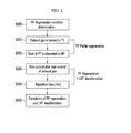
- FIG. 2 is a flowchart showing an exhaust gas after-treatmenfi method according to an exemplary embodiment of the present disclosure.
- step S200 determines the regeneration condition of the particulate matter filter 150.
- the regeneration condition is satisfied when the soot amount trapped in the particulate matter filter 150, the travel distance, the travel time, or the pressure difference between an upstream side and a downstream side of the particulate matter filter 150 are within predetermined conditions.
- the temperature of the exhaust gas flowing through the exhaust line 160 is raised to a temperature T1 (about 650 degrees Celsius) in step S210.
- the temperature of the exhaust gas may be raised in multiple steps by the main injector 125, the post-injection injector 132, or an intake air controller.
- the particulate matter trapped in the particulate matter filter 150 is eliminated to a predetermined level M1 in step S220.
- the predetermined level M1 may be a value at which the particulate matter filter cannot be damaged by DTI (Drop To Idle) or DTO (Drop To Overrun).
- the sulfur compound is eliminated from the nitrogen oxide purifier 140 after the particulate matter filter 150 is completely regenerated, the time that the exhaust gas temperature is sustained at a high temperature longer, and the particulate matter filter 150 and the nitrogen oxide purifier 140 may be degraded by the high temperature. After a predetermined amount of particulate matter trapped in the particulate matter filter 150 is eliminated, the desulfation mode of the nitrogen oxide purifier 140 reduces fuel consumption and prevents the degradation of the particulate matter filter 150 and the nitrogen oxide purifier 140.
- step S230 the condition of the exhaust gas flowing into the nitrogen oxide purifier 140 is controlled to be in a lean state. Accordingly, the temperature of the nitrogen oxide purifier 140 is securely sustained to be less than 700 Celsius degrees.
- the exhaust gas in the nitrogen oxide purifier 140 is in the lean state, the exhaust gas is transformed to a rich state again.
- the temperature of the nitrogen oxide purifier 140 is controlled to be between the desulfation minimum temperature and desulfation high maximum temperature, thereby eliminating the sulfur compound absorbed in the nitrogen oxide purifier.
- step S240 The condition of the exhaust gas alternately repeats the lean state and the rich state in step S240. Afterwards regenerating the particulate matter filter 150, the desulfation of the nitrogen oxide purifier 140 is completed in step S250.
- the exhaust gas regenerates the particulate matter filter 150 in a lean state after the desulfation of the nitrogen oxide purifier 140 is completed.
- the regeneration completion of the particulate matter filter 150 may be determined when amount of trapped particulate matter is less than a predetermined level, the regeneration time passes a predetermined value, or the pressure difference is less than a predetermined value.
- the desulfation condition of the nitrogen oxide purifier 140 is when the amount of sulfur compound thereof is less than a predetermined value, the desulfation time is longer than a predetermined value, or the sum of the rich condition sustaining time is longer than a predetermined value.
- the time that the exhaust gas is being sustained in a lean state and the exhaust gas in a rich state can be predetermined.
- the time can be varied by the exhaust gas temperature in the particulate matter filter 150 or the nitrogen oxide purifier 140.
- FIG. 3 is a graph showing temperature of a nitrogen oxide purifier in an exhaust gas after-treatment method according to an exemplary embodiment of the present disclosure.
- a horizontal axis denotes time and a vertical axis denotes temperature of nitrogen oxide purifier.
- the temperature of the nitrogen oxide purifier 140 or the particulate matter filter 150 can be calculated with the temperature of the exhaust gas where the exhaust gas temperature may be the temperature of the nitrogen oxide purifier 140 or the particulate matter filter 150.
- the temperature of the exhaust gas is raised from about 600 to 700 degrees Celsius so as to regenerate the particulate matter filter 150.
- the desulfation of the nitrogen oxide purifier 140 is performed during the regeneration of the particulate matter filter 150.
- a first temperature line in which the exhaust gas condition is transformed from a lean to a rich state and a second temperature line in which the exhaust gas condition is transformed from a rich to a lean state have different characteristics from each other.
- the temperature of the nitrogen oxide purifier140 descends to be stable. And, the temperature thereof is sustained to be from 650 to 700 degrees Celsius again.
- the temperature of the nitrogen oxide purifier 140 can be raised to exceed 700 degrees Celsius, and this condition can damage the nitrogen oxide purifier 140 or can deteriorate exhaust gas purification performance.
- the desulfation mode of the nitrogen oxide purifier 140 is performed to reduce the fuel consumption and to prevent the degradation of the particulate matter filter 150 and the nitrogen oxide purifier 140.
- the exhaust gas is controlled to be in a rich state to securely control the temperature of the nitrogen oxide purifier 140 and prevent the degradation thereof.
Landscapes
- Engineering & Computer Science (AREA)
- Chemical & Material Sciences (AREA)
- Combustion & Propulsion (AREA)
- Mechanical Engineering (AREA)
- General Engineering & Computer Science (AREA)
- Chemical Kinetics & Catalysis (AREA)
- Processes For Solid Components From Exhaust (AREA)
- Exhaust Gas After Treatment (AREA)
- Electrical Control Of Air Or Fuel Supplied To Internal-Combustion Engine (AREA)
Abstract
Description
- This application claims priority to and the benefit of Korean Patent Application No.
10-2012-0143086 - The present disclosure relates to an exhaust gas after-treatment method, and more particularly, to an exhaust gas after-treatment method controlling a temperature of exhaust gas to eliminate sulfur from a nitrogen oxide purifier and particulate matter from a particulate matter filter.
- Generally, a particulate matter filter filters particulate matter (PM) included in exhaust gas. Further, the filtered particulate matter is burned at high temperature to be eliminated. The elimination of PM is called "regeneration".
- A nitrogen oxide purifier (LNT: lean NOx trap) absorbs nitrogen oxide included in the exhaust gas where the nitrogen oxide is reduced by a reaction with a reducing agent under predetermined conditions.
- In a case in which the nitrogen oxide purifier is disposed at a downstream side of an exhaust manifold, and the particulate matter filter at a downstream side of the nitrogen oxide purifier, sulfur components move with the exhaust gas to be continuously absorbed in the nitrogen oxide purifier.
- The sulfur compound absorbed in the nitrogen oxide purifier deteriorates the nitrogen oxide purification performance, and therefore, the sulfur component has to be cyclically eliminated.
- Further, a high temperature condition is necessary to eliminate the sulfur component while the particulate matter filter is being regenerated. A process for eliminating the sulfur component from the nitrogen oxide purifier during the regeneration of the particulate matter filter has been developed. However, when the sulfur components are eliminated during the regeneration of the particulate matter filter, the nitrogen oxide purifier can be damaged by an excessive high temperature, thus deteriorating the purification performance.
- The above information disclosed in this Background section is only for enhancement of understanding of the background of the disclosure, and therefore may contain information that does not form the prior art already known in this country to a person of ordinary skill in the art.
- The present disclosure has been made in an effort to provide an exhaust gas after-treatment method having advantages of preventing a nitrogen oxide purifier in a sulfur elimination process from overheating during a regeneration of a particulate matter filter.
- An exhaust gas after-treatment method according to an exemplary embodiment of the present disclosure comprises determining a regeneration condition of a particulate matterfilter, eliminating trapped particulate matter up to a predetermined amount by raising a temperature of exhaust gas up to a first value so as to regenerate the particulate matter filter. Exhaust gas that flows into a nitrogen oxide purifier is controlled in a lean condition (air/fuel ratio > 14.5) while the particulate matter filter is being regenerated. Sulfur components are eliminated from the nitrogen oxide purifier by controlling exhaust gas that flows into the nitrogen oxide purifier after the lean condition is performed. The lean condition and a rich condition (air/fuel ratio < 14.5) are repeated. The regeneration of the particulate matter filter or the elimination of the sulfur components from the nitrogen oxide purifier is completed.
- The nitrogen oxide purifier may be disposed at a downstream side of the particulate matter filter or disposed at a downstream side of the exhaust manifold.
- The first value may range from 600 to 700 degrees Celsius. The temperature of exhaust gas may be raised to the first value in multiple steps to protect the particulate matter filter. The temperature of the exhaust gas flowing into the nitrogen oxide purifier may be controlled to be lower than 700 degrees Celsius such that the particulate matter trapped in the particulate matter filter is eliminated in the lean condition or may be controlled to be between a sulfur elimination minimum temperature and a sulfur elimination maximum temperature in the eliminating of the sulfur components from the nitrogen oxide purifier.
- The regeneration condition of the particulate matter filter may be determined by an amount of the particulate matter trapped in the particulate matter filter, travel distance, a travel time, or a front/rear side pressure difference of the particulate matter filter.
- The temperature of the exhaust gas flowing into the particulate matter filter or the nitrogen oxide purifier may be controlled by a main injector injecting fuel into a combustion chamber, an intake air controller, or a post-injection injector.
- The completion of the regeneration of the particulate matter filter may be determined by the particulate matter trapped in the particulate matter filter, front/rear pressure difference, or regeneration time.
- The completion of the sulfur elimination of the nitrogen oxide purifier may be determined by a sulfur amount stored in the nitrogen oxide device, a sulfur elimination time, or a sum of the rich condition duration time in the sulfur elimination process.
- The exhaust gas may be controlled to be in a lean condition when the sulfur elimination of the nitrogen oxide purifier is completed, and the regeneration of the particulate matter filter device is not completed.
- As described above, in an exhaust gas after-treatment method, after exhaust gas is controlled to be in a lean condition, the exhaust gas is controlled to be in a rich condition so as to eliminate sulfur components from the nitrogen oxide purifier during the regeneration of the particulate matter filter to prevent overheating of the nitrogen oxide purifier.
-
-
FIG. 1 is a schematic diagram of an exhaust gas after-treatment system according to an exemplary embodiment of the present disclosure. -
FIG. 2 is a flowchart showing an exhaust gas after-treatment method according to an exemplary embodiment of the present disclosure. -
FIG. 3 is a graph showing temperature of a nitrogen oxide purifier in an exhaust gas after-treatment method according to an exemplary embodiment of the present disclosure. - An exemplary embodiment of the present disclosure will hereinafter be described in detail with reference to the accompanying drawings.
- Referring to
FIG. 1 , an exhaust gas after-treatment system illustrates an exemplary embodiment for understanding of the present disclosure. Further, the present disclosure is not limited thereto and can be applied to various engine systems. - An exhaust gas after-treatment system includes an
intake line 100, athrottle valve 105, anintake manifold 110, acombustion chamber 120, amain injector 125, anexhaust manifold 130, apost-injection injector 132, atemperature sensor 135,oxygen sensors exhaust line 160, anitrogen oxide purifier 140, aparticulate matter filter 150, and adifferential pressure sensor 155. Themain injector 125, which can perform the function of the post-injection injector without the post-injection injector, injects fuel into thecombustion chamber 120, and thepost-injection injector 132 injects fuel into theexhaust line 160. Themain injector 125 generates engine torque through fuel combustion. Further, themain injector 125 and thepost-injection injector 132 control the condition of exhaust gas passing through theexhaust line 160 to a lean or rich state and controls the temperature of the exhaust gas. - The
oxygen sensors controller 170. Thecontroller 170 determines whether the condition of the exhaust gas is lean or rich based on the received signals. - The
throttle valve 105 controls intake air amount, thetemperature sensor 135 detects the temperature of the exhaust gas passing through theexhaust line 160, and thedifferential pressure sensor 155 detects pressure difference between upstream side and downstream side of the particulate matter filter. - The
controller 170 determines whether the regeneration condition for eliminating soot trapped in theparticulate matter filter 150 is satisfied or not based on the differential pressure signal, travel distance, or travel time. - When the regeneration condition for the
particulate matter filter 150 is satisfied, the temperature of the exhaust gas is raised to about 650 degrees Celsius to regenerate theparticulate matter filter 150. - Further, the
controller 170 performs a desulfation mode of thenitrogen oxide purifier 140 when the particulate matter trapped in theparticulate matter filter 150 is reduced to a predetermined level, - When the desulfation mode begins, the condition of the exhaust gas flowing into the
nitrogen oxide purifier 140 is controlled to the lean state such that the temperature of the exhaust gas flowing into thenitrogen oxide purifier 140 is securely sustained. Also, the exhaust gas flowing into thenitrogen oxide purifier 140 is controlled to be in the rich state, such that sulfur compounds are eliminated. - The
particulate matter filter 150 is continuously regenerated while the exhaust gas is repeatedly cycled from the lean to the rich state and the rich to the lean state. - After the desulfation of the
nitrogen oxide purifier 140 is completed, the exhaust gas is controlled to be in the lean state to complete the regeneration of theparticulate matter filter 150. -
FIG. 2 is a flowchart showing an exhaust gas after-treatmenfi method according to an exemplary embodiment of the present disclosure. - Referring to
FIG. 2 , step S200 determines the regeneration condition of theparticulate matter filter 150. The regeneration condition is satisfied when the soot amount trapped in theparticulate matter filter 150, the travel distance, the travel time, or the pressure difference between an upstream side and a downstream side of theparticulate matter filter 150 are within predetermined conditions. - The temperature of the exhaust gas flowing through the
exhaust line 160 is raised to a temperature T1 (about 650 degrees Celsius) in step S210. In this step, the temperature of the exhaust gas may be raised in multiple steps by themain injector 125, thepost-injection injector 132, or an intake air controller. - The particulate matter trapped in the
particulate matter filter 150 is eliminated to a predetermined level M1 in step S220. In this step, the predetermined level M1 may be a value at which the particulate matter filter cannot be damaged by DTI (Drop To Idle) or DTO (Drop To Overrun). - In a case in which the sulfur compound is eliminated from the
nitrogen oxide purifier 140 after theparticulate matter filter 150 is completely regenerated, the time that the exhaust gas temperature is sustained at a high temperature longer, and theparticulate matter filter 150 and thenitrogen oxide purifier 140 may be degraded by the high temperature. After a predetermined amount of particulate matter trapped in theparticulate matter filter 150 is eliminated, the desulfation mode of thenitrogen oxide purifier 140 reduces fuel consumption and prevents the degradation of theparticulate matter filter 150 and thenitrogen oxide purifier 140. - In step S230, the condition of the exhaust gas flowing into the
nitrogen oxide purifier 140 is controlled to be in a lean state. Accordingly, the temperature of thenitrogen oxide purifier 140 is securely sustained to be less than 700 Celsius degrees. - After the exhaust gas in the
nitrogen oxide purifier 140 is in the lean state, the exhaust gas is transformed to a rich state again. In this step, the temperature of thenitrogen oxide purifier 140 is controlled to be between the desulfation minimum temperature and desulfation high maximum temperature, thereby eliminating the sulfur compound absorbed in the nitrogen oxide purifier. - The condition of the exhaust gas alternately repeats the lean state and the rich state in step S240. Afterwards regenerating the
particulate matter filter 150, the desulfation of thenitrogen oxide purifier 140 is completed in step S250. - The exhaust gas regenerates the
particulate matter filter 150 in a lean state after the desulfation of thenitrogen oxide purifier 140 is completed. - The regeneration completion of the
particulate matter filter 150 may be determined when amount of trapped particulate matter is less than a predetermined level, the regeneration time passes a predetermined value, or the pressure difference is less than a predetermined value. - The desulfation condition of the
nitrogen oxide purifier 140 is when the amount of sulfur compound thereof is less than a predetermined value, the desulfation time is longer than a predetermined value, or the sum of the rich condition sustaining time is longer than a predetermined value. - The time that the exhaust gas is being sustained in a lean state and the exhaust gas in a rich state can be predetermined. The time can be varied by the exhaust gas temperature in the
particulate matter filter 150 or thenitrogen oxide purifier 140. -
FIG. 3 is a graph showing temperature of a nitrogen oxide purifier in an exhaust gas after-treatment method according to an exemplary embodiment of the present disclosure. - Referring to
FIG. 3 , a horizontal axis denotes time and a vertical axis denotes temperature of nitrogen oxide purifier. The temperature of thenitrogen oxide purifier 140 or theparticulate matter filter 150 can be calculated with the temperature of the exhaust gas where the exhaust gas temperature may be the temperature of thenitrogen oxide purifier 140 or theparticulate matter filter 150. - As shown in the drawings, the temperature of the exhaust gas is raised from about 600 to 700 degrees Celsius so as to regenerate the
particulate matter filter 150. - The desulfation of the
nitrogen oxide purifier 140 is performed during the regeneration of theparticulate matter filter 150. Here, a first temperature line in which the exhaust gas condition is transformed from a lean to a rich state and a second temperature line in which the exhaust gas condition is transformed from a rich to a lean state have different characteristics from each other. - As shown in the first temperature line, the temperature of the nitrogen oxide purifier140 descends to be stable. And, the temperature thereof is sustained to be from 650 to 700 degrees Celsius again. In the second temperature line, there is a danger that the temperature of the
nitrogen oxide purifier 140 can be raised to exceed 700 degrees Celsius, and this condition can damage thenitrogen oxide purifier 140 or can deteriorate exhaust gas purification performance. - As described above, only predetermined amount of the particulate matter trapped by the
particulate matter filter 150 is eliminated, and the desulfation mode of thenitrogen oxide purifier 140 is performed to reduce the fuel consumption and to prevent the degradation of theparticulate matter filter 150 and thenitrogen oxide purifier 140. - Further, while the
particulate matter filter 150 is being regenerated, after the exhaust gas is in a lean state so as to eliminate sulfur from thenitrogen oxide purifier 140, the exhaust gas is controlled to be in a rich state to securely control the temperature of thenitrogen oxide purifier 140 and prevent the degradation thereof. - While the disclosure has been described in connection with what is presently considered to be practical exemplary embodiments, it is to be understood that the inventive concept is not limited to the disclosed embodiments, but, on the contrary, is intended to cover various modifications and equivalent arrangements included within the spirit and scope of the appended claims.
Claims (11)
- An exhaust gas after-treatment method, comprising:determining a regeneration condition of a particulate matter filter;eliminating a trapped particulate matter up to a predetermined amount by raising a temperature of an exhaust gas to a first predetermined value so as to regenerate the particulate matter filter;controlling an exhaust gas that flows into a nitrogen oxide purifier in a lean condition while the particulate matter filter is being regenerated;eliminating sulfur components from the nitrogen oxide purifier by controlling exhaust gas that flows into the nitrogen oxide purifier after the lean condition is performed; andrepeating the lean condition and a rich condition, and completing the regeneration of the particulate matter filter, or completing the elimination of the sulfur components from the nitrogen oxide purifier.
- The exhaust gas after-treatment method of claim 1, wherein the first value ranges from 600 to 700 degrees Celsius.
- The exhaust gas after-treatment method of claim 1 or 2, wherein a temperature of exhaust gas is raised to the first value in multiple steps to protect the particulate matter filter.
- The exhaust gas after-treatment method of claim 1, wherein the nitrogen oxide purifier is disposed at a downstream side of the exhaust manifold.
- The exhaust gas after-treatment method of claim 1, wherein a temperature of the exhaust gas flowing into the nitrogen oxide purifier is controlled to be lower than 700 degrees Celsius such that the particulate matter trapped in the particulate matter filter is eliminated in the lean condition.
- The exhaust gas after-treatment method of claim 1, wherein the temperature of the exhaust gas flowing into the nitrogen oxide purifier is controlled to be between a sulfur elimination minimum temperature and a sulfur elimination maximum temperature in the eliminating of the sulfur components from the nitrogen oxide purifier.
- The exhaust gas after-treatment method of claim 1, wherein the regeneration condition of the particulate matter filter is determined by an amount of the particulate matter trapped in the particulate matter filter, a travel distance, a travel time, or a front/rear side pressure difference of the particulate matter filter.
- The exhaust gas after-treatment method of claim 1, wherein the temperature of the exhaust gas flowing into the particulate matter filter or the nitrogen oxide purifier is controlled by a main injector injecting fuel into a combustion chamber, an intake air control device, or a post-injection injector.
- The exhaust gas after-treatment method of claim 1, wherein a completion of the regeneration of the particulate matter filter is determined by an amount of the particulate matter trapped in the particulate matter filter, a front/rear pressure difference, or a regeneration time.
- The exhaust gas after-treatment method of claim 1, wherein a completion of the sulfur elimination of the nitrogen oxide purifier is determined by a sulfur amount that is formed in the nitrogen oxide device, a sulfur elimination time, or a sum of the rich condition duration time in the sulfur elimination process.
- The exhaust gas after-treatment method of claim 1, wherein the exhaust gas is controlled to be in a lean condition when the sulfur elimination of the nitrogen oxide purifier is completed and the regeneration of the particulate matter filter is not completed.
Applications Claiming Priority (1)
| Application Number | Priority Date | Filing Date | Title |
|---|---|---|---|
| KR1020120143086A KR20140074770A (en) | 2012-12-10 | 2012-12-10 | Exhaust gas treatment method |
Publications (1)
| Publication Number | Publication Date |
|---|---|
| EP2740912A1 true EP2740912A1 (en) | 2014-06-11 |
Family
ID=49035485
Family Applications (1)
| Application Number | Title | Priority Date | Filing Date |
|---|---|---|---|
| EP13182129.0A Withdrawn EP2740912A1 (en) | 2012-12-10 | 2013-08-29 | Exhaust gas after-treatment method |
Country Status (5)
| Country | Link |
|---|---|
| US (1) | US20140157759A1 (en) |
| EP (1) | EP2740912A1 (en) |
| JP (1) | JP2014114802A (en) |
| KR (1) | KR20140074770A (en) |
| CN (1) | CN103867261A (en) |
Families Citing this family (2)
| Publication number | Priority date | Publication date | Assignee | Title |
|---|---|---|---|---|
| CN108930570B (en) * | 2018-06-28 | 2019-09-03 | 常熟理工学院 | A method for reducing engine particulate matter emission |
| KR102257395B1 (en) * | 2019-10-11 | 2021-05-26 | 서울대학교산학협력단 | Apparatus for controlling engine emission aftertreatment system |
Citations (2)
| Publication number | Priority date | Publication date | Assignee | Title |
|---|---|---|---|---|
| US7918082B2 (en) * | 2003-11-24 | 2011-04-05 | Institut Francais Du Petrole | Method and device intended for desulfation of a nitric oxide trap and regeneration of a particle filter |
| DE10164931B4 (en) * | 2001-05-31 | 2011-07-07 | Daimler AG, 70327 | Process for desulfurizing a nitrogen oxide storage catalyst in a diesel engine comprises heating the catalyst above a determined lowest desulfurization temperature, and operating the engine in a lean-rich alternating method |
Family Cites Families (17)
| Publication number | Priority date | Publication date | Assignee | Title |
|---|---|---|---|---|
| DE10023439A1 (en) * | 2000-05-12 | 2001-11-22 | Dmc2 Degussa Metals Catalysts | Process for removing nitrogen oxides and soot particles from the lean exhaust gas of an internal combustion engine and exhaust gas purification system therefor |
| JP4241032B2 (en) * | 2002-12-26 | 2009-03-18 | 日産自動車株式会社 | Sulfur poisoning release control device for diesel engine catalyst |
| DE10308287B4 (en) * | 2003-02-26 | 2006-11-30 | Umicore Ag & Co. Kg | Process for exhaust gas purification |
| JP4225153B2 (en) * | 2003-07-30 | 2009-02-18 | 日産自動車株式会社 | Exhaust filter regeneration control device |
| US6988361B2 (en) * | 2003-10-27 | 2006-01-24 | Ford Global Technologies, Llc | Method and system for controlling simultaneous diesel particulate filter regeneration and lean NOx trap desulfation |
| US20070012032A1 (en) * | 2005-07-12 | 2007-01-18 | Eaton Corporation | Hybrid system comprising HC-SCR, NOx-trapping, and NH3-SCR for exhaust emission reduction |
| EP1745836A1 (en) * | 2005-07-21 | 2007-01-24 | Ford Global Technologies, LLC | A method and an arrangement for purifying exhaust gas in an internal combustion engine |
| US7677028B2 (en) * | 2006-02-28 | 2010-03-16 | Caterpillar Inc. | Particulate trap regeneration temperature control system |
| US8209960B2 (en) * | 2006-07-21 | 2012-07-03 | International Engine Intellectual Property Company, Llc | System and method for coupled DPF regeneration and LNT DeNOx |
| DE102006034805A1 (en) * | 2006-07-27 | 2008-01-31 | Robert Bosch Gmbh | Diesel particulate filter regenerating and nitrogen oxide storage catalyst desulphurizing method for internal combustion engine, involves triggering combined complete or partial regeneration of filter and desulphurization of catalyst |
| KR100836367B1 (en) * | 2006-11-21 | 2008-06-09 | 현대자동차주식회사 | Purifier for Reducing Particulate Matter and Nitrogen Oxide in Diesel Engine |
| US7543446B2 (en) * | 2006-12-20 | 2009-06-09 | Cummins, Inc. | System for controlling regeneration of exhaust gas aftertreatment components |
| US7788910B2 (en) * | 2007-05-09 | 2010-09-07 | Ford Global Technologies, Llc | Particulate filter regeneration and NOx catalyst re-activation |
| JP4910932B2 (en) * | 2007-08-01 | 2012-04-04 | トヨタ自動車株式会社 | Exhaust gas purification device for internal combustion engine |
| US20100275582A1 (en) * | 2008-01-08 | 2010-11-04 | Honda Motor Co., Ltd. | Exhaust emission control device for internal combustion engine |
| US8701390B2 (en) * | 2010-11-23 | 2014-04-22 | International Engine Intellectual Property Company, Llc | Adaptive control strategy |
| DE102011007364A1 (en) * | 2011-04-14 | 2012-10-18 | Robert Bosch Gmbh | Method and apparatus for regeneration of a particulate filter in a Y exhaust system |
-
2012
- 2012-12-10 KR KR1020120143086A patent/KR20140074770A/en not_active Ceased
-
2013
- 2013-04-24 JP JP2013091696A patent/JP2014114802A/en active Pending
- 2013-08-28 US US14/012,133 patent/US20140157759A1/en not_active Abandoned
- 2013-08-29 EP EP13182129.0A patent/EP2740912A1/en not_active Withdrawn
- 2013-09-16 CN CN201310421542.1A patent/CN103867261A/en active Pending
Patent Citations (2)
| Publication number | Priority date | Publication date | Assignee | Title |
|---|---|---|---|---|
| DE10164931B4 (en) * | 2001-05-31 | 2011-07-07 | Daimler AG, 70327 | Process for desulfurizing a nitrogen oxide storage catalyst in a diesel engine comprises heating the catalyst above a determined lowest desulfurization temperature, and operating the engine in a lean-rich alternating method |
| US7918082B2 (en) * | 2003-11-24 | 2011-04-05 | Institut Francais Du Petrole | Method and device intended for desulfation of a nitric oxide trap and regeneration of a particle filter |
Also Published As
| Publication number | Publication date |
|---|---|
| KR20140074770A (en) | 2014-06-18 |
| CN103867261A (en) | 2014-06-18 |
| US20140157759A1 (en) | 2014-06-12 |
| JP2014114802A (en) | 2014-06-26 |
Similar Documents
| Publication | Publication Date | Title |
|---|---|---|
| CN107762650B (en) | Method for controlling an exhaust gas purification system | |
| US8555619B2 (en) | Exhaust system | |
| EP2253823B1 (en) | Exhaust emission control device | |
| US10287944B2 (en) | Exhaust purification system and method of desulfurizing lean NOx trap of exhaust purification system provided with lean NOx trap and selective catalytic reduction catalyst | |
| EP2559876B1 (en) | Exhaust gas purification device, and control method for exhaust gas purification device | |
| EP1873369A1 (en) | Regeneration of a diesel particulate filter | |
| CN107435575B (en) | Method for regenerating diesel particulate filter | |
| EP3184787B1 (en) | Regeneration device for exhaust-gas purifying device | |
| CN107429589B (en) | Exhaust gas purification system and catalyst regeneration method | |
| US20120023904A1 (en) | Exhaust gas post processing system and control method thereof | |
| CN113047971A (en) | Method and device for preventing engine particle number from exceeding standard | |
| US8555620B2 (en) | Exhaust gas aftertreatment method | |
| US20140157759A1 (en) | Exhaust gas after-treatment method | |
| JP6769281B2 (en) | Internal combustion engine system | |
| KR101409994B1 (en) | Diesel Particulate Filter regeneration method of Exhaust gas after treatment device for diesel engine | |
| KR102072193B1 (en) | Exhaust gas treatment system comprising a catalytic particulate filter, and corresponding method | |
| US7784275B2 (en) | Optimization of hydrocarbon injection during diesel particulate filter (DPF) regeneration | |
| JP2016176428A (en) | Exhaust emission control device for engine | |
| JP6569873B2 (en) | Engine exhaust purification system | |
| JP4957216B2 (en) | Exhaust gas purification device for internal combustion engine | |
| US20130061582A1 (en) | Exhaust gas purification system in upland area | |
| KR102249588B1 (en) | Exhaust gas post processing apparatus and control method thereof | |
| JP7147214B2 (en) | Engine exhaust gas state estimation method, catalyst abnormality determination method, and engine catalyst abnormality determination device | |
| JP7106923B2 (en) | Engine exhaust gas state estimation method, catalyst abnormality determination method, and engine catalyst abnormality determination device | |
| CN100439666C (en) | Optimization of Hydrocarbon Injection During Diesel Particulate Filter Regeneration |
Legal Events
| Date | Code | Title | Description |
|---|---|---|---|
| PUAI | Public reference made under article 153(3) epc to a published international application that has entered the european phase |
Free format text: ORIGINAL CODE: 0009012 |
|
| 17P | Request for examination filed |
Effective date: 20130829 |
|
| AK | Designated contracting states |
Kind code of ref document: A1 Designated state(s): AL AT BE BG CH CY CZ DE DK EE ES FI FR GB GR HR HU IE IS IT LI LT LU LV MC MK MT NL NO PL PT RO RS SE SI SK SM TR |
|
| AX | Request for extension of the european patent |
Extension state: BA ME |
|
| R17P | Request for examination filed (corrected) |
Effective date: 20140918 |
|
| RBV | Designated contracting states (corrected) |
Designated state(s): AL AT BE BG CH CY CZ DE DK EE ES FI FR GB GR HR HU IE IS IT LI LT LU LV MC MK MT NL NO PL PT RO RS SE SI SK SM TR |
|
| STAA | Information on the status of an ep patent application or granted ep patent |
Free format text: STATUS: THE APPLICATION IS DEEMED TO BE WITHDRAWN |
|
| 18D | Application deemed to be withdrawn |
Effective date: 20160301 |