EP2740617A2 - Trailer coupling lock and fastening means - Google Patents
Trailer coupling lock and fastening means Download PDFInfo
- Publication number
- EP2740617A2 EP2740617A2 EP13196012.2A EP13196012A EP2740617A2 EP 2740617 A2 EP2740617 A2 EP 2740617A2 EP 13196012 A EP13196012 A EP 13196012A EP 2740617 A2 EP2740617 A2 EP 2740617A2
- Authority
- EP
- European Patent Office
- Prior art keywords
- sleeve
- trailer coupling
- thread
- support means
- coupling lock
- Prior art date
- Legal status (The legal status is an assumption and is not a legal conclusion. Google has not performed a legal analysis and makes no representation as to the accuracy of the status listed.)
- Granted
Links
Images


Classifications
-
- B—PERFORMING OPERATIONS; TRANSPORTING
- B60—VEHICLES IN GENERAL
- B60D—VEHICLE CONNECTIONS
- B60D1/00—Traction couplings; Hitches; Draw-gear; Towing devices
- B60D1/58—Auxiliary devices
- B60D1/60—Covers, caps or guards, e.g. comprising anti-theft devices
-
- B—PERFORMING OPERATIONS; TRANSPORTING
- B60—VEHICLES IN GENERAL
- B60D—VEHICLE CONNECTIONS
- B60D1/00—Traction couplings; Hitches; Draw-gear; Towing devices
- B60D1/01—Traction couplings or hitches characterised by their type
- B60D1/06—Ball-and-socket hitches
Definitions
- the invention relates to a trailer coupling lock for blocking operation of a release handle of a trailer coupling.
- the invention also concerns a fastening means for adjustable fastening at objects of different sizes.
- a trailer coupling 2 is a device that is designed to connect a trailer to a traction vehicle, see Figure 1 .
- the trailer coupling is usually firmly joined to the trailer and has a recess in which a towing hook 101 of the traction vehicle fits whereby the traction vehicle may pull the trailer when they are connected.
- Figure 1 discloses a trailer coupling 2 with the portion where the tow ball of the towing hook 101 engages the trailer coupling in a cross section.
- a locking means that lockingly engages with a towing ball of the towing hook when connected together, whereby the trailer coupling is prevented from coming loose during a ride when it is connected.
- the trailer coupling also has a release handle 102 that when operated releases the locking device at the recess in the trailer coupling such that it lets the tow ball go, whereby the trailer coupling can be removed from the towing hook.
- a common version of a trailer coupling lock 200 is shown in figure 2 and can be said to resemble a sleeve that is slipped over the trailer coupling when it is in a mounted state on a car. It can also be used in a non-mounted state for the trailer coupling, for instance when the trailer is parked without being connected to a traction vehicle.
- the described trailer coupling lock 200 according to figure 2 is mounted by being slipped over a large part of the trailer coupling in a direction from the towing hook and backwards over the trailer coupling. In this mounted state, a front edge of the trailer coupling lock blocks the release handle of the trailer coupling.
- a padlock 201 introduced in holes of two stand-up flanges, prevents, together with a lower surface of the trailer coupling lock, the trailer coupling lock from being able to be removed from the trailer coupling.
- trailer coupling locks for instance such where a tailor-made housing in synthetic material is slipped over and completely encloses the release handle and parts of the trailer coupling and thereby precludes the release handle from being operated.
- Such locks with a housing for the release handle can have a lock cylinder that penetrates through the material of the trailer coupling and by that locks the trailer coupling lock to it.
- trailer coupling locks do not fit all trailer couplings.
- the first variant of trailer coupling locks mentioned can be adapted to work with trailer coupling locks of different sizes, but there are limitations.
- Such a trailer coupling lock of a relatively large size functions badly with smaller trailer couplings since openings between the trailer coupling and the lock make the lock fit badly and can be used as points of attack for a break attempt.
- the second type of trailer coupling lock that is tailor-made, can in general only be used with a specific, therefore adapted, trailer coupling.
- a main object therefore, is to propose an improved trailer coupling lock that to a higher extent can be used with trailer couplings of different sizes.
- This trailer coupling lock solves the above problem by that it comprises an adjustable fastening means with which the trailer coupling lock can be permanently fixed at trailer couplings of different sizes.
- the fastening means comprises two support means and when fastening the trailer coupling lock on a trailer coupling, at least one of the support means is adjusted in relation to the other such that they together clamp the trailer coupling between each other in a fixed position.
- this support means comprising a portion with a thread and a sleeve that can be screwed off and on the thread of the portion, such that its distance to the trailer coupling can be adjusted.
- both support means clamps a trailer coupling between each other
- they are fixed to the trailer coupling by a fixing screw that is mounted through one of the support means, then through the trailer coupling and finally through the other support means.
- the head of the fixing screw is countersinked in a recess in one of the support means and the head is sealed such that no tool is able to reach and rotate the screw.
- the length of the fixing screw is adapted such that its other end does not protrude outside the second support means and can therefore not be manipulated with a tool.
- the sleeve of the at least one adjustable support means also comprises a second thread, the pitch of which differs from the pitch of the first thread.
- the second thread engages with the fixing screw in the fixed position.
- the trailer coupling lock can be adapted to trailer couplings of different sizes by rotating the sleeve of the first support means and thereby is adjusted to clamp a desired trailer coupling between itself and the opposite support means.
- the sleeve is locked by having the fixing screw thereafter mounted through the support means, through the trailer coupling and be screwed into the second thread of the sleeve.
- the head of the fixing screw When the head of the fixing screw has been sealed, it can no longer be unscrewed; the other end of it is out of reach for a tool and the screw can therefore not be unscrewed from this direction either.
- the sleeve of the adjustable support means is fixed by the pitch of the two different threads. Therefore, the trailer coupling lock is permanently fixed at the trailer coupling.
- trailer coupling locks The most common principle for trailer coupling locks is that they in some way block a release handle of a trailer coupling such that the trailer coupling can not be opened. Also the trailer coupling lock according to the present invention uses this principle.
- Figure 3 discloses a trailer coupling lock 1 for blocking operation of a release handle of a trailer coupling.
- the trailer coupling lock comprises an adjustable fastening means 4 for fastening the trailer coupling lock 1 on trailer couplings of different sizes.
- the trailer coupling lock further comprises a blocking portion 3 to which a blocking device 22 (shown in Figure 5 ) can be connected and be locked, in a way that it can be unlocked, in order to together block operation of the release handle in a locked position.
- the fastening means 4 comprises a first 5 and a second 6 support means located opposite at a distance from each other and mutually fixed.
- At least the first support means 5 comprises a portion 7 with a thread 8 and further a sleeve 9 with a first thread 10 which can be screwed off and on the thread 8 of the portion 7 such that the sleeve 9 can be adjusted to clamp a trailer coupling 2 (not shown in Fig. 3 ) between the sleeve 9 and the second support means 6 in a fixed position.
- the sleeve 9 is shown unscrewed from the portion 7 in figure 4 . Inside the sleeve 9 is a second thread 11 located, the pitch of said second thread 11 is different from the pitch of the first thread 10 of the sleeve 9.
- the fastening means 4 further comprises a fixing screw 12 with a screw head 13 (shown in figure 4 ) and a thread 14, which thread 14 fits with the second thread 11 of the sleeve 9.
- the second support means 6 has a recess 15 (not visible in Fig. 3 ) in which the head 13 of the fixing screw 12 completely can be countersinked such that the head 13 is closely enclosed by the second support means 6. This is not apparent from figure 3 since the second support means 6 is directed in the other direction in the figure; the head 13 of the fixing screw 12 is on the rear end of the second support means 6 in the figure.
- the fixing screw 12 is introduced through the second support means 6, through a trailer coupling 2 (not shown in figure 3 ) fixed between the sleeve 9 and the second support means 6, and further is screwed with its thread 14 into the second thread 11 (shown in figure 4 ) inside the sleeve 9, and lies with its head 13 in the recess 15 of the second support means 6 (not shown in figure 3 ) and against the second support means 6 such that an axial displacement of the fixing screw 12 in a direction towards the sleeve 9 is prevented, and wherein the head 13 of the fixing screw 12 in the fixed position is sealed to prevent an unscrewing of the fixing screw 12 with a screwing tool.
- trailer coupling lock can be permanently fastened on trailer couplings of different sizes.
- the second support means 6 can comprise a portion 16 with a thread 17 and further a sleeve 18 with thread 19 which can be screwed off and on the portion 16 of the second support means.
- the sleeve 18 can be adjusted to clamp a trailer coupling 2 between the sleeve 18 and the sleeve 9 of the first support means and wherein the recess 15 of the second support means 6 is located in the sleeve 18 of the second support means.
- the screw head 13 in the fixed position of the described variants of the trailer coupling lock can be sealed with for instance one into a recess of the screw head driven stop ball.
- a ball can be made of steel and when it is driven into the recess for a rotation tool of the screw head, such as a recess for a screwdriver or a hexagon wrench, it will be impossible to remove if its proportions in view of the recess are the right ones.
- An example thereof is a spherical ball that dimensionwise just about can be driven into a hexagonal recess in the screw head. In this way, the ball constitutes a seal or sealing of the screw head and prevents the screw from being unscrewed again.
- Examples of other ways of sealing the recess in the screw head are to completely or partly fill or cover it with a small weld, in everyday language a welding dot.
- a mechanical modifying of the screw head is of course possible, for instance cutting off of the part that comprises the recess with an angle grinder or other powerful cutting tool.
- Many other variants are possible, for instance weakened screw heads which breaks at a load with a certain torque.
- the trailer coupling lock has, as previously mentioned, a blocking portion to which a blocking device can be connected and locked. When these are connected in the right position they prevent the operation of a release handle. The locking of the blocking device to the blocking portion prevents any unauthorised person from disconnecting the blocking device and operating the release handle.
- the connection of the blocking device to the blocking portion can happen in several ways.
- the blocking portion 3 itself can for instance, as is shown in figure 3 , be arranged to receive a blocking device 22 (an example shown in figure 5 ) with one in the blocking device 22 integrated locking mechanism with which the locking of the blocking device 22 to the blocking portion 3 can happen.
- the blocking portion 3 comprises two protruding bars 20, 21.
- the bars has a free end 25, 26 which are adapted to receive a blocking device by way of a recess that is suggested in the free end 25 of bar 21.
- a corresponding recess may be present in bar 26 but is facing away from the eye of the observer in figure 3 .
- a locking block 22 be used as a blocking device 22.
- a locking block is meant a block with an integrated lock of the same type that is used for a U-lock for bicycles and motorcycles.
- Embodiments of the blocking portion 3 of the trailer coupling lock that have been described above function with both a separate blocking device that is not part of the trailer coupling lock and with a blocking device that is integrated in the trailer coupling lock.
- the embodiments that are shown as examples in figures 3-7 are all of the type where the blocking device 22 is not integrated but is separate from the trailer coupling lock.
- the blocking device must of course in use be mounted on the trailer coupling lock for it to be effective in blocking a release handle of a trailer coupling.
- a blocking device in the form of, on the market available, suitable devices.
- suitable devices are locking bars or locking blocks from U-locks, padlocks or other means that can be connected to a suitably formed blocking portion. In this way, a user can procure a trailer coupling lock according to the invention and in use supplement it with such a device available separately on the market.
- all described embodiments of the blocking portion of the trailer coupling lock function with both a separate blocking device and with a blocking device that is integrated in the trailer coupling lock.
- a blocking device can be mentioned that in one end is articulatedly joined with an end of the blocking portion and in another end of the blocking device is connectible with another end of the blocking portion and is lockable with this.
- the blocking device can articulatedly be removed from a release handle of a trailer coupling to enable operation of the release handle.
- the blocking device may be articulatedly brought towards the release handle and be connected with the blocking portion, according to the previous paragraph, whereupon they together block the release handle from being operated.
- figure 3 is only one possible physical implementation of all different physical implementations that are possible according to the principles described above.
- a trailer coupling lock 1 where the blocking portion 3 comprises two points of attachment 23, 24 is shown. Further, the blocking portion 3 comprises two bars 20, 21, each attached with one end in a corresponding one of the points of attachments 23, 24 and are adjustably protruding from these and are each terminated in a second end 25, 26 with which the blocking device 22 is connectible to be able to be locked to the bars 20, 21. In this way it is enabled that the blocking portion 3 can be adjusted to be adapted to different release handles.
- the trailer coupling lock receives a further dimension of adaptability to different trailer couplings. With that, the trailer coupling can be adjusted to trailer couplings with different placements of release handles, for instance further away from a point of attachment for the trailer coupling lock on the trailer coupling or closer to such a point of attachment.
- the adjustability of the bars 20, 21 of the trailer coupling lock 1 in the preceding paragraph can be achieved by the bars 20, 21 being joined by threads with the points of attachment 23, 24. That brings a simple adjustability, the fine adjustment of which can be controlled by the choice of the pitch of the threads in the threaded connection between the bars 20, 21 and the points of attachment 23, 24.
- Another variant for the adjustability of the bars 20, 21 is that these comprises means along their length that are connectable with the points of attachment by way of a bayonet coupling principle. For instance with protruding protrusions along the lengths of the bars that with a turning hooks into recesses in the points of attachments.
- An example of such a fastening means of another construction can be a fastening means adapted for fixed fastening to a trailer coupling without adjustability.
- a fastening means adapted for fixed fastening to a trailer coupling without adjustability.
- a screw or bolt that is slipped through the trailer coupling lock and the trailer coupling to connect them with each other.
- the screw/bolt can be fixed by a suitable sealing, for instance by welding between this and a part of the trailer coupling or trailer coupling lock.
- Figure 6 discloses an example with a trailer coupling lock 1 according to the invention mounted on a trailer coupling 2.
- the trailer coupling lock 1 is firmly fixed on the trailer coupling 2 and the blocking portion 3 is ready to receive a blocking device in order to together block the operation of the release handle 102.
- the trailer coupling 2 is not blocked by the trailer coupling lock and the trailer coupling 2 can therefore be mounted on or dismounted from a towing hook in this state.
- Figure 7 discloses an example with a trailer coupling lock 1 according to the invention mounted on a trailer coupling 2.
- the trailer coupling lock 1 is firmly fixed on the trailer coupling 2 and on the blocking portion 3, a blocking device 22 is mounted in order to together block the operation of the release handle 102.
- the trailer coupling 2 is blocked by the trailer coupling lock 1 and the trailer coupling 2 is therefore prevented from being mounted on or dismounted from a towing hook in this state.
- the trailer coupling lock according to the invention can be made in many different materials, for instance steel, aluminium, other metals or synthetic materials. On a pure functional basis, all such materials mentioned work, but considering resistance to break attempts on the trailer coupling lock, the trailer coupling should for that reason be made of a strong, high-strength material, such as such materials that are traditionally used for for instance U-locks or padlocks.
- the invention comprises a fastening means for adjustable fastening at objects of different sizes.
- the fastening means comprises:
- the fastening means corresponds in construction with the construction of the fastening means of the trailer coupling lock above. Accordingly, all embodiments of the fastening means of the trailer coupling lock described above are also applicable to this fastening means for adjustable fastening at objects of different sizes.
- This fastening means for adjustable fastening at objects of different sizes makes a connection between this fastening means and objects of different sizes possible. What is needed is that the object that is to be connected with the fastening means has at least one portion that dimensionwise fits into the space that arises by the placement of the support means at a distance from each other.
- any object that has a sufficiently stable physical construction can be clamped in the fastening means.
- the fastening means can in turn already be connected with a another object at a place of the fastening means that does not intrude upon the described fastening mechanism itself with support means and sleeve of the fastening means. Accordingly, a connection of this other object to said objects of different sizes is enabled with the help of the fastening means.
Landscapes
- Engineering & Computer Science (AREA)
- Transportation (AREA)
- Mechanical Engineering (AREA)
- Lock And Its Accessories (AREA)
- Gloves (AREA)
- Body Structure For Vehicles (AREA)
Abstract
Description
- The invention relates to a trailer coupling lock for blocking operation of a release handle of a trailer coupling. The invention also concerns a fastening means for adjustable fastening at objects of different sizes.
- A
trailer coupling 2 is a device that is designed to connect a trailer to a traction vehicle, seeFigure 1 . The trailer coupling is usually firmly joined to the trailer and has a recess in which atowing hook 101 of the traction vehicle fits whereby the traction vehicle may pull the trailer when they are connected.Figure 1 discloses atrailer coupling 2 with the portion where the tow ball of thetowing hook 101 engages the trailer coupling in a cross section. - At the recess of the trailer coupling there is a locking means that lockingly engages with a towing ball of the towing hook when connected together, whereby the trailer coupling is prevented from coming loose during a ride when it is connected.
- The trailer coupling also has a
release handle 102 that when operated releases the locking device at the recess in the trailer coupling such that it lets the tow ball go, whereby the trailer coupling can be removed from the towing hook. - To prevent any unauthorised person from stealing a trailer from a vehicle by disconnecting the trailer, connect it to another vehicle and drive away with it, a number of different trailer coupling locks have been proposed. Their general functioning are by, in different ways, preventing operation of the release handle of a trailer coupling.
- A common version of a
trailer coupling lock 200 is shown infigure 2 and can be said to resemble a sleeve that is slipped over the trailer coupling when it is in a mounted state on a car. It can also be used in a non-mounted state for the trailer coupling, for instance when the trailer is parked without being connected to a traction vehicle. - The described
trailer coupling lock 200 according tofigure 2 is mounted by being slipped over a large part of the trailer coupling in a direction from the towing hook and backwards over the trailer coupling. In this mounted state, a front edge of the trailer coupling lock blocks the release handle of the trailer coupling. Apadlock 201, introduced in holes of two stand-up flanges, prevents, together with a lower surface of the trailer coupling lock, the trailer coupling lock from being able to be removed from the trailer coupling. - There are also other models of trailer coupling locks, for instance such where a tailor-made housing in synthetic material is slipped over and completely encloses the release handle and parts of the trailer coupling and thereby precludes the release handle from being operated. Such locks with a housing for the release handle can have a lock cylinder that penetrates through the material of the trailer coupling and by that locks the trailer coupling lock to it.
- A disadvantage with such known trailer coupling locks is that they do not fit all trailer couplings. The first variant of trailer coupling locks mentioned can be adapted to work with trailer coupling locks of different sizes, but there are limitations. Such a trailer coupling lock of a relatively large size functions badly with smaller trailer couplings since openings between the trailer coupling and the lock make the lock fit badly and can be used as points of attack for a break attempt.
- The second type of trailer coupling lock, that is tailor-made, can in general only be used with a specific, therefore adapted, trailer coupling.
- It is an object of the present invention to propose a solution or a reduction of the problems with the prior art. A main object therefore, is to propose an improved trailer coupling lock that to a higher extent can be used with trailer couplings of different sizes.
- According to the invention this is accomplished with a trailer coupling lock according to
claim 1. - This trailer coupling lock solves the above problem by that it comprises an adjustable fastening means with which the trailer coupling lock can be permanently fixed at trailer couplings of different sizes.
- The fastening means comprises two support means and when fastening the trailer coupling lock on a trailer coupling, at least one of the support means is adjusted in relation to the other such that they together clamp the trailer coupling between each other in a fixed position.
- The adjustability of said at least one adjustable support means arise by this support means comprising a portion with a thread and a sleeve that can be screwed off and on the thread of the portion, such that its distance to the trailer coupling can be adjusted.
- When at least one support means has been adjusted such that both support means clamps a trailer coupling between each other, they are fixed to the trailer coupling by a fixing screw that is mounted through one of the support means, then through the trailer coupling and finally through the other support means.
- The head of the fixing screw is countersinked in a recess in one of the support means and the head is sealed such that no tool is able to reach and rotate the screw. The length of the fixing screw is adapted such that its other end does not protrude outside the second support means and can therefore not be manipulated with a tool.
- The sleeve of the at least one adjustable support means also comprises a second thread, the pitch of which differs from the pitch of the first thread. The second thread engages with the fixing screw in the fixed position.
- Owing to the threads of the sleeve having different pitch, it is prevented from a further adjustment when the fixing screw is screwed in through it, since a rotation attempt of the sleeve causes the sleeve to want to move with one speed along the portion with which its first thread engages but with another speed along the fixing screw with which its second thread engages. This has the effect that the sleeve is fixed in one and the same position.
- Thus, the trailer coupling lock can be adapted to trailer couplings of different sizes by rotating the sleeve of the first support means and thereby is adjusted to clamp a desired trailer coupling between itself and the opposite support means. The sleeve is locked by having the fixing screw thereafter mounted through the support means, through the trailer coupling and be screwed into the second thread of the sleeve.
- When the head of the fixing screw has been sealed, it can no longer be unscrewed; the other end of it is out of reach for a tool and the screw can therefore not be unscrewed from this direction either. Finally, the sleeve of the adjustable support means is fixed by the pitch of the two different threads. Therefore, the trailer coupling lock is permanently fixed at the trailer coupling.
- Further advantageous embodiments of the invention are stated in the dependent claims.
- According to
claim 10, also a problem with fastening of a fastening means at objects of different sizes is solved. Due to the adjustability, a fastening means that can be adapted to adjustably clamp different objects of different sizes is achieved. - Embodiments that exemplify the invention will now be described with reference to the attached drawings on which
-
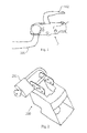
Fig. 1 discloses a towing hook with a trailer coupling mounted, -
Fig. 2 discloses a prior art trailer coupling lock, -
Fig. 3 discloses a trailer coupling lock according to the invention without a locking bar, -
Fig. 4 discloses a trailer coupling lock according to the invention with its constituents in a partly disassembled condition, -
Fig. 5 discloses a trailer coupling lock according to the invention with a locking bar partly mounted, -
Fig. 6 discloses a trailer coupling lock according to the invention mounted on a trailer coupling and without a locking bar, and -
Fig. 7 discloses a trailer coupling lock according to the invention mounted on a trailer coupling and with a locking bar. - The most common principle for trailer coupling locks is that they in some way block a release handle of a trailer coupling such that the trailer coupling can not be opened. Also the trailer coupling lock according to the present invention uses this principle.
-
Figure 3 discloses atrailer coupling lock 1 for blocking operation of a release handle of a trailer coupling. - The trailer coupling lock comprises an adjustable fastening means 4 for fastening the
trailer coupling lock 1 on trailer couplings of different sizes. The trailer coupling lock further comprises ablocking portion 3 to which a blocking device 22 (shown inFigure 5 ) can be connected and be locked, in a way that it can be unlocked, in order to together block operation of the release handle in a locked position. - The fastening means 4 comprises a first 5 and a second 6 support means located opposite at a distance from each other and mutually fixed.
- At least the first support means 5 comprises a portion 7 with a
thread 8 and further asleeve 9 with afirst thread 10 which can be screwed off and on thethread 8 of the portion 7 such that thesleeve 9 can be adjusted to clamp a trailer coupling 2 (not shown inFig. 3 ) between thesleeve 9 and the second support means 6 in a fixed position. - The
sleeve 9 is shown unscrewed from the portion 7 infigure 4 . Inside thesleeve 9 is asecond thread 11 located, the pitch of saidsecond thread 11 is different from the pitch of thefirst thread 10 of thesleeve 9. - Returning to
figure 3 , the fastening means 4 further comprises afixing screw 12 with a screw head 13 (shown infigure 4 ) and athread 14, which thread 14 fits with thesecond thread 11 of thesleeve 9. - The second support means 6 has a recess 15 (not visible in
Fig. 3 ) in which thehead 13 of the fixingscrew 12 completely can be countersinked such that thehead 13 is closely enclosed by the second support means 6. This is not apparent fromfigure 3 since the second support means 6 is directed in the other direction in the figure; thehead 13 of the fixingscrew 12 is on the rear end of the second support means 6 in the figure. - In the fixed position, the fixing
screw 12 is introduced through the second support means 6, through a trailer coupling 2 (not shown infigure 3 ) fixed between thesleeve 9 and the second support means 6, and further is screwed with itsthread 14 into the second thread 11 (shown infigure 4 ) inside thesleeve 9, and lies with itshead 13 in therecess 15 of the second support means 6 (not shown infigure 3 ) and against the second support means 6 such that an axial displacement of the fixingscrew 12 in a direction towards thesleeve 9 is prevented, and wherein thehead 13 of the fixingscrew 12 in the fixed position is sealed to prevent an unscrewing of the fixingscrew 12 with a screwing tool. - By this construction of the trailer coupling lock, a rotation attempt, in the fixed position, on the
sleeve 9, in a direction that wants to carry thesleeve 9 away from the fixed trailer coupling, causes a locking of thesleeve 9 by means of the twodifferent threads sleeve 9 with different pitches. Thus, thesleeve 9 is prevented from being unscrewed from thetrailer coupling 2 in the fixed position. - In this way, the trailer coupling lock can be permanently fastened on trailer couplings of different sizes.
- As a variant, of the described
trailer coupling lock 1 and with reference tofigure 4 , also the second support means 6 can comprise aportion 16 with athread 17 and further asleeve 18 withthread 19 which can be screwed off and on theportion 16 of the second support means. In this way, thesleeve 18 can be adjusted to clamp atrailer coupling 2 between thesleeve 18 and thesleeve 9 of the first support means and wherein therecess 15 of the second support means 6 is located in thesleeve 18 of the second support means. - The
screw head 13 in the fixed position of the described variants of the trailer coupling lock can be sealed with for instance one into a recess of the screw head driven stop ball. Such a ball can be made of steel and when it is driven into the recess for a rotation tool of the screw head, such as a recess for a screwdriver or a hexagon wrench, it will be impossible to remove if its proportions in view of the recess are the right ones. An example thereof is a spherical ball that dimensionwise just about can be driven into a hexagonal recess in the screw head. In this way, the ball constitutes a seal or sealing of the screw head and prevents the screw from being unscrewed again. Examples of other ways of sealing the recess in the screw head are to completely or partly fill or cover it with a small weld, in everyday language a welding dot. Also, a mechanical modifying of the screw head is of course possible, for instance cutting off of the part that comprises the recess with an angle grinder or other powerful cutting tool. Many other variants are possible, for instance weakened screw heads which breaks at a load with a certain torque. - Thus far, the fastening of the trailer coupling lock on a trailer coupling. For the actual blocking of the release handle of a trailer coupling, the trailer coupling lock has, as previously mentioned, a blocking portion to which a blocking device can be connected and locked. When these are connected in the right position they prevent the operation of a release handle. The locking of the blocking device to the blocking portion prevents any unauthorised person from disconnecting the blocking device and operating the release handle.
- The connection of the blocking device to the blocking portion can happen in several ways. For all described variants of the trailer coupling lock, the blocking
portion 3 itself can for instance, as is shown infigure 3 , be arranged to receive a blocking device 22 (an example shown infigure 5 ) with one in the blockingdevice 22 integrated locking mechanism with which the locking of the blockingdevice 22 to the blockingportion 3 can happen. - In the example of this embodiment that is shown in
figure 3 , the blockingportion 3 comprises two protrudingbars free end free end 25 ofbar 21. A corresponding recess may be present inbar 26 but is facing away from the eye of the observer infigure 3 . - For this blocking portion, that is adapted to receive a blocking device having an integrated locking mechanism, can for instance a locking
block 22 be used as a blockingdevice 22. This is shown infigure 5 . With a locking block is meant a block with an integrated lock of the same type that is used for a U-lock for bicycles and motorcycles. Such a solution is rational since it can use already existing such locking blocks and avoid the cost of developing a separate blocking device with an integrated locking mechanism. - Of course, there is nothing that prevents the locking mechanism for the locking of the connection between the blocking portion and the blocking device, as an alternative to the embodiment above, from being located in the blocking portion. This is not shown in any drawing.
- Embodiments of the blocking
portion 3 of the trailer coupling lock that have been described above function with both a separate blocking device that is not part of the trailer coupling lock and with a blocking device that is integrated in the trailer coupling lock. - The embodiments that are shown as examples in
figures 3-7 are all of the type where the blockingdevice 22 is not integrated but is separate from the trailer coupling lock. However, the blocking device must of course in use be mounted on the trailer coupling lock for it to be effective in blocking a release handle of a trailer coupling. It is, however, possible to adapt the blocking portion of the trailer coupling lock such that it can be supplemented with a blocking device in the form of, on the market available, suitable devices. Examples of such suitable devices that can be used are locking bars or locking blocks from U-locks, padlocks or other means that can be connected to a suitably formed blocking portion. In this way, a user can procure a trailer coupling lock according to the invention and in use supplement it with such a device available separately on the market. - As mentioned above, all described embodiments of the blocking portion of the trailer coupling lock function with both a separate blocking device and with a blocking device that is integrated in the trailer coupling lock. As an example of such an integrated blocking device, a blocking device can be mentioned that in one end is articulatedly joined with an end of the blocking portion and in another end of the blocking device is connectible with another end of the blocking portion and is lockable with this.
- In this way the blocking device can articulatedly be removed from a release handle of a trailer coupling to enable operation of the release handle. When such a release handle is to be blocked, the blocking device may be articulatedly brought towards the release handle and be connected with the blocking portion, according to the previous paragraph, whereupon they together block the release handle from being operated.
- The above described variants of the blocking portion and thereto adapted blocking device are described in principle and may take different physical manifestations. They have been described with reference to, i.a.,
figure 3 . In fact,figure 3 is only one possible physical implementation of all different physical implementations that are possible according to the principles described above. - A further advantageous principle that is apparent from
figure 3 will now be described. It can be combined with all principles and embodiments of the trailer coupling lock described above. - In
figure 3 , atrailer coupling lock 1 where the blockingportion 3 comprises two points ofattachment portion 3 comprises twobars attachments second end blocking device 22 is connectible to be able to be locked to thebars portion 3 can be adjusted to be adapted to different release handles. This brings the further advantage that the trailer coupling lock receives a further dimension of adaptability to different trailer couplings. With that, the trailer coupling can be adjusted to trailer couplings with different placements of release handles, for instance further away from a point of attachment for the trailer coupling lock on the trailer coupling or closer to such a point of attachment. - The adjustability of the
bars trailer coupling lock 1 in the preceding paragraph can be achieved by thebars attachment bars attachment - Another variant for the adjustability of the
bars - The above described variants of the adjustable blocking portion can be combined with all earlier described variants of the trailer coupling lock.
- It is also possible to make the adjustable blocking portion independent of the adjustable fastening means. Thus, a trailer coupling lock as described above is possible in all its different variants where the adjustable fastening means has been replaced by a fastening means of another construction than the adjustable fastening means above.
- An example of such a fastening means of another construction can be a fastening means adapted for fixed fastening to a trailer coupling without adjustability. For instance a screw or bolt that is slipped through the trailer coupling lock and the trailer coupling to connect them with each other. The screw/bolt can be fixed by a suitable sealing, for instance by welding between this and a part of the trailer coupling or trailer coupling lock.
- It is also possible that such a fastening means of another construction than has been described above in this application can be of an adjustable type, but which uses another principle than the adjustable fastening means in this application.
-
Figure 6 discloses an example with atrailer coupling lock 1 according to the invention mounted on atrailer coupling 2. In the figure, thetrailer coupling lock 1 is firmly fixed on thetrailer coupling 2 and the blockingportion 3 is ready to receive a blocking device in order to together block the operation of therelease handle 102. Thus, in this position, thetrailer coupling 2 is not blocked by the trailer coupling lock and thetrailer coupling 2 can therefore be mounted on or dismounted from a towing hook in this state. -
Figure 7 discloses an example with atrailer coupling lock 1 according to the invention mounted on atrailer coupling 2. In the figure, thetrailer coupling lock 1 is firmly fixed on thetrailer coupling 2 and on the blockingportion 3, a blockingdevice 22 is mounted in order to together block the operation of therelease handle 102. Thus, in this position, thetrailer coupling 2 is blocked by thetrailer coupling lock 1 and thetrailer coupling 2 is therefore prevented from being mounted on or dismounted from a towing hook in this state. - The trailer coupling lock according to the invention can be made in many different materials, for instance steel, aluminium, other metals or synthetic materials. On a pure functional basis, all such materials mentioned work, but considering resistance to break attempts on the trailer coupling lock, the trailer coupling should for that reason be made of a strong, high-strength material, such as such materials that are traditionally used for for instance U-locks or padlocks.
- Further, the invention comprises a fastening means for adjustable fastening at objects of different sizes. To this end, the fastening means comprises:
- a first and a second support means located opposite at a distance from each other and mutually fixed,
- wherein at least the first support means comprises a portion with a thread and further a sleeve with a first thread which can be screwed off and on the thread of the portion such that the sleeve can be adjusted to clamp an object between the sleeve and the second support means in a fixed position,
- wherein inside the sleeve is a second thread located, the pitch of said second thread is different from the pitch of the first thread of the sleeve,
- wherein the fastening means further comprises a fixing screw with a screw head and a thread, which thread fits with the second thread of the sleeve,
- wherein the second support means has a recess in which the head of the fixing screw can be completely countersinked such that the head is closely enclosed by the second support means,
- wherein the fixing screw, in the fixed position, is introduced through the second support means, through an object fixed between the sleeve and the second support means, and further is screwed with its thread into the second thread inside the sleeve, and lies with its head in the recess of the second support means and against the second support means such that an axial displacement of the fixing screw in a direction towards the sleeve is prevented, and wherein the head of the fixing screw in the fixed position is sealed to prevent an unscrewing of the fixing screw with a screwing tool,
- The fastening means corresponds in construction with the construction of the fastening means of the trailer coupling lock above. Accordingly, all embodiments of the fastening means of the trailer coupling lock described above are also applicable to this fastening means for adjustable fastening at objects of different sizes.
- This fastening means for adjustable fastening at objects of different sizes makes a connection between this fastening means and objects of different sizes possible. What is needed is that the object that is to be connected with the fastening means has at least one portion that dimensionwise fits into the space that arises by the placement of the support means at a distance from each other.
- Any object that has a sufficiently stable physical construction can be clamped in the fastening means. The fastening means can in turn already be connected with a another object at a place of the fastening means that does not intrude upon the described fastening mechanism itself with support means and sleeve of the fastening means. Accordingly, a connection of this other object to said objects of different sizes is enabled with the help of the fastening means.
-
- 1. Trailer coupling lock
- 2. Trailer coupling
- 3. Blocking portion
- 4. Fastening means
- 5. First support means
- 6. Second support means
- 7. Portion of first support means
- 8. Thread of portion of first support means
- 9. Sleeve of first support means
- 10. First thread of sleeve of first support means
- 11. Second thread of sleeve of first support means
- 12. Fixing screw
- 13. Screw head
- 14. Thread of fixing screw
- 15. Recess of second support means
- 16. Portion of second support means
- 17. Thread of portion of second support means
- 18. Sleeve of second support means
- 19. Thread of sleeve of second support means
- 20. Bar
- 21. Bar
- 22. Blocking device
- 23. Point of attachment
- 24. Point of attachment
- 25. End of bar
- 26. End of bar
- 101. Towing hook
- 102. Release handle
Claims (10)
- Trailer coupling lock (1) for blocking operation of a release handle of a trailer coupling (2),- wherein the trailer coupling lock comprises an adjustable fastening means (4) for fastening the trailer coupling lock (1) on trailer couplings of different sizes, and wherein the trailer coupling lock further comprises a blocking portion (3) to which a blocking device (22) can be connected and be locked, in a way that it can be unlocked, in order to together block operation of the release handle in a locked position,- wherein the fastening means (4) comprises a first (5) and a second (6) support means located opposite at a distance from each other and mutually fixed,- wherein at least the first support means (5) comprises a portion (7) with a thread (8) and further a sleeve (9) with a first thread (10) which can be screwed off and on the thread (8) of the portion (7) such that the sleeve (9) can be adjusted to clamp a trailer coupling (2) between the sleeve (9) and the second support means (6) in a fixed position,- wherein inside the sleeve (9) is a second thread (11) located, the pitch of said second thread (11) is different from the pitch of the first thread (10) of the sleeve (9),- wherein the fastening means (4) further comprises a fixing screw (12) with a screw head (13) and a thread (14), which thread (14) fits with the second thread (11) of the sleeve (9),- wherein the second support means (6) has a recess (15) in which the head (13) of the fixing screw (12) can be completely countersinked such that the head (13) is closely enclosed by the second support means (6),- wherein the fixing screw (12), in the fixed position, is introduced through the second support means (6), through a trailer coupling (2) fixed between the sleeve (9) and the second support means (6), and further is screwed with its thread (14) into the second thread (11) inside the sleeve (9), and lies with its head (13) in the recess (15) of the second support means (6) and against the second support means (6) such that an axial displacement of the fixing screw (12) in a direction towards the sleeve (9) is prevented, and wherein the head (13) of the fixing screw (12) in the fixed position is sealed to prevent an unscrewing of the fixing screw (12) with a screwing tool,whereby, in the fixed position, a rotation attempt on the sleeve (9), in a direction that wants to carry the sleeve (9) away from the fixed trailer coupling (2), causes a locking of the sleeve (9) by means of the two different threads (10, 11) of the sleeve (9) with different pitches such that the sleeve (9) is prevented from being unscrewed from the trailer coupling (2) in the fixed position.
- Trailer coupling lock (1) according to claim 1, wherein also the second support means (6) comprises a portion (16) with a thread (17) and further a sleeve (18) with thread (19) which can be screwed off and on the portion (16) of the second support means such that the sleeve (18) can be adjusted to clamp a trailer coupling (2) between the sleeve (18) and the sleeve (9) of the first support means and wherein the recess (15) of the second support means (6) is located in the sleeve (18) of the second support means.
- Trailer coupling lock (1) according to any of claims 1 - 2, wherein the screw head (13) in the fixed position is sealed with any of: one into a recess of the screw head driven stop ball or a welding dot.
- Trailer coupling lock (1) according to any of claims 1 - 3, wherein the blocking portion (3) is adapted to receive a blocking device (22) with one in this device integrated locking mechanism with which the locking of the blocking device (22) to the blocking portion (3) can happen.
- Trailer coupling lock (1) according to the preceding claim, wherein the blocking portion (3) is adapted to receive a locking block (22) as a blocking device (22).
- Trailer coupling lock (1) according to any of claims 1 - 3, wherein the blocking portion (3) comprises a locking mechanism adapted for the locking of the blocking device (22) to the blocking portion (3).
- Trailer coupling lock (1) according to any of claims 1 - 6, wherein the blocking device (22) is a part of the trailer coupling lock (1).
- Trailer coupling lock (1) according to any of claims 1 - 7, wherein the blocking portion (3) comprises two points of attachment (23, 24) and further comprises two bars (20, 21) each attached with one end in a corresponding one of the points of attachments (23, 24) and are adjustably protruding from these and are each terminated in a second end (25, 26) with which the blocking device (22) is connectible to be able to be locked to the bars (20, 21), whereby the blocking portion (3) can be adjusted to be adapted to different release handles.
- Trailer coupling lock (1) according to claim 8, wherein the bars (20, 21) are joined by threads with the points of attachment (23, 24) whereby the adjustability of the bars in the protruding direction arise.
- Fastening means for adjustable fastening at objects of different sizes, wherein the fastening means comprises:- a first and a second support means located opposite at a distance from each other and mutually fixed,- wherein at least the first support means comprises a portion with a thread and further a sleeve with a first thread which can be screwed off and on the thread of the portion such that the sleeve can be adjusted to clamp an object between the sleeve and the second support means in a fixed position,- wherein inside the sleeve is a second thread located, the pitch of said second thread is different from the pitch of the first thread of the sleeve,- wherein the fastening means further comprises a fixing screw with a screw head and a thread, which thread fits with the second thread of the sleeve,- wherein the second support means has a recess in which the head of the fixing screw can be completely countersinked such that the head is closely enclosed by the second support means,- wherein the fixing screw, in the fixed position, is introduced through the second support means, through an object fixed between the sleeve and the second support means, and further is screwed with its thread into the second thread inside the sleeve, and lies with its head in the recess of the second support means and against the second support means such that an axial displacement of the fixing screw in a direction towards the sleeve is prevented, and wherein the head of the fixing screw in the fixed position is sealed to prevent an unscrewing of the fixing screw with a screwing tool,whereby, in the fixed position, a rotation attempt on the sleeve, in a direction that wants to carry the sleeve away from the fixed object, causes a locking of the sleeve by means of the two different threads with different pitches of the sleeve such that the sleeve is prevented from being unscrewed from the object in the fixed position.
Applications Claiming Priority (1)
| Application Number | Priority Date | Filing Date | Title |
|---|---|---|---|
| SE1251394A SE536734C2 (en) | 2012-12-07 | 2012-12-07 | Adjustable ball glove |
Publications (3)
| Publication Number | Publication Date |
|---|---|
| EP2740617A2 true EP2740617A2 (en) | 2014-06-11 |
| EP2740617A3 EP2740617A3 (en) | 2014-08-13 |
| EP2740617B1 EP2740617B1 (en) | 2019-02-13 |
Family
ID=50241054
Family Applications (1)
| Application Number | Title | Priority Date | Filing Date |
|---|---|---|---|
| EP13196012.2A Not-in-force EP2740617B1 (en) | 2012-12-07 | 2013-12-06 | Trailer coupling lock and fastening means |
Country Status (2)
| Country | Link |
|---|---|
| EP (1) | EP2740617B1 (en) |
| SE (1) | SE536734C2 (en) |
Family Cites Families (4)
| Publication number | Priority date | Publication date | Assignee | Title |
|---|---|---|---|---|
| US3391555A (en) * | 1967-12-20 | 1968-07-09 | Anthony Mamo | Locking device for a trailer hitch |
| DE8633616U1 (en) * | 1986-12-16 | 1987-02-12 | Larsson, Karl Gunnar, Eskilstuna | Locking device for a coupling, in particular a trailer coupling |
| GB2218678A (en) * | 1988-05-10 | 1989-11-22 | Alan Place | Security device for theft prevention of a caravan or towable trailer when attached to the towing mechanism of a vehicle |
| DE10249940A1 (en) * | 2002-10-26 | 2004-05-06 | Rudolf Bullinger | Anti-theft device for trailer of lorry has cross sections of inside passages of lower and upper sections matched to larger size of towing bar and adaptable to smaller size by at least one reducing piece |
-
2012
- 2012-12-07 SE SE1251394A patent/SE536734C2/en not_active IP Right Cessation
-
2013
- 2013-12-06 EP EP13196012.2A patent/EP2740617B1/en not_active Not-in-force
Non-Patent Citations (1)
| Title |
|---|
| None |
Also Published As
| Publication number | Publication date |
|---|---|
| SE536734C2 (en) | 2014-07-01 |
| EP2740617A3 (en) | 2014-08-13 |
| EP2740617B1 (en) | 2019-02-13 |
| SE1251394A1 (en) | 2014-06-08 |
Similar Documents
| Publication | Publication Date | Title |
|---|---|---|
| US5290057A (en) | Trailor hitch | |
| US8556288B1 (en) | Lockbox for a coupler of a trailer | |
| US6889995B2 (en) | Hitch locking mechanism | |
| US8882149B2 (en) | Steering device | |
| US9868326B2 (en) | Assemblies for towing | |
| US5832753A (en) | Lock assembly | |
| US20060208457A1 (en) | Hitch locking mechanism | |
| EP2740617B1 (en) | Trailer coupling lock and fastening means | |
| JP2012007662A (en) | Theft prevention bolt and jig used for theft prevention bolt | |
| US1696523A (en) | Lock nut | |
| CN1750964A (en) | Anti-theft device for maneuvering the vehicle via the handlebars | |
| US20080067783A1 (en) | Hitch lock | |
| CN211001169U (en) | Safe camera for looking around dead zone of automobile | |
| US6526789B1 (en) | Lockable anti-wobble hitch pin | |
| CN210436075U (en) | Cross anti-theft bolt and assembling and disassembling tool | |
| US20050273984A1 (en) | Locking quick-release collar | |
| US11358535B2 (en) | Attachment system | |
| US11724767B2 (en) | Quickly detachable and rotatable bicycle handlebar stem | |
| US20040164518A1 (en) | Hitch locking mechanism | |
| CN210760107U (en) | Double-ball-head dragging device | |
| US8876143B1 (en) | Locking mechanism for trailer hitch | |
| GB2381842A (en) | Cover for fastener | |
| CN102108999A (en) | License plate bolt | |
| KR840000713Y1 (en) | Car anti-theft device | |
| DE3511562C2 (en) |
Legal Events
| Date | Code | Title | Description |
|---|---|---|---|
| PUAI | Public reference made under article 153(3) epc to a published international application that has entered the european phase |
Free format text: ORIGINAL CODE: 0009012 |
|
| 17P | Request for examination filed |
Effective date: 20131206 |
|
| AK | Designated contracting states |
Kind code of ref document: A2 Designated state(s): AL AT BE BG CH CY CZ DE DK EE ES FI FR GB GR HR HU IE IS IT LI LT LU LV MC MK MT NL NO PL PT RO RS SE SI SK SM TR |
|
| AX | Request for extension of the european patent |
Extension state: BA ME |
|
| PUAL | Search report despatched |
Free format text: ORIGINAL CODE: 0009013 |
|
| AK | Designated contracting states |
Kind code of ref document: A3 Designated state(s): AL AT BE BG CH CY CZ DE DK EE ES FI FR GB GR HR HU IE IS IT LI LT LU LV MC MK MT NL NO PL PT RO RS SE SI SK SM TR |
|
| AX | Request for extension of the european patent |
Extension state: BA ME |
|
| RIC1 | Information provided on ipc code assigned before grant |
Ipc: B60D 1/06 20060101AFI20140708BHEP Ipc: B60D 1/60 20060101ALI20140708BHEP |
|
| R17P | Request for examination filed (corrected) |
Effective date: 20150207 |
|
| RBV | Designated contracting states (corrected) |
Designated state(s): AL AT BE BG CH CY CZ DE DK EE ES FI FR GB GR HR HU IE IS IT LI LT LU LV MC MK MT NL NO PL PT RO RS SE SI SK SM TR |
|
| STAA | Information on the status of an ep patent application or granted ep patent |
Free format text: STATUS: REQUEST FOR EXAMINATION WAS MADE |
|
| GRAP | Despatch of communication of intention to grant a patent |
Free format text: ORIGINAL CODE: EPIDOSNIGR1 |
|
| STAA | Information on the status of an ep patent application or granted ep patent |
Free format text: STATUS: GRANT OF PATENT IS INTENDED |
|
| INTG | Intention to grant announced |
Effective date: 20180703 |
|
| GRAS | Grant fee paid |
Free format text: ORIGINAL CODE: EPIDOSNIGR3 |
|
| GRAA | (expected) grant |
Free format text: ORIGINAL CODE: 0009210 |
|
| STAA | Information on the status of an ep patent application or granted ep patent |
Free format text: STATUS: THE PATENT HAS BEEN GRANTED |
|
| AK | Designated contracting states |
Kind code of ref document: B1 Designated state(s): AL AT BE BG CH CY CZ DE DK EE ES FI FR GB GR HR HU IE IS IT LI LT LU LV MC MK MT NL NO PL PT RO RS SE SI SK SM TR |
|
| REG | Reference to a national code |
Ref country code: GB Ref legal event code: FG4D |
|
| REG | Reference to a national code |
Ref country code: CH Ref legal event code: EP Ref country code: AT Ref legal event code: REF Ref document number: 1095974 Country of ref document: AT Kind code of ref document: T Effective date: 20190215 |
|
| REG | Reference to a national code |
Ref country code: IE Ref legal event code: FG4D |
|
| REG | Reference to a national code |
Ref country code: DE Ref legal event code: R096 Ref document number: 602013050725 Country of ref document: DE |
|
| REG | Reference to a national code |
Ref country code: LT Ref legal event code: MG4D |
|
| REG | Reference to a national code |
Ref country code: NL Ref legal event code: MP Effective date: 20190213 |
|
| PG25 | Lapsed in a contracting state [announced via postgrant information from national office to epo] |
Ref country code: PT Free format text: LAPSE BECAUSE OF FAILURE TO SUBMIT A TRANSLATION OF THE DESCRIPTION OR TO PAY THE FEE WITHIN THE PRESCRIBED TIME-LIMIT Effective date: 20190613 Ref country code: NL Free format text: LAPSE BECAUSE OF FAILURE TO SUBMIT A TRANSLATION OF THE DESCRIPTION OR TO PAY THE FEE WITHIN THE PRESCRIBED TIME-LIMIT Effective date: 20190213 Ref country code: LT Free format text: LAPSE BECAUSE OF FAILURE TO SUBMIT A TRANSLATION OF THE DESCRIPTION OR TO PAY THE FEE WITHIN THE PRESCRIBED TIME-LIMIT Effective date: 20190213 Ref country code: NO Free format text: LAPSE BECAUSE OF FAILURE TO SUBMIT A TRANSLATION OF THE DESCRIPTION OR TO PAY THE FEE WITHIN THE PRESCRIBED TIME-LIMIT Effective date: 20190513 Ref country code: FI Free format text: LAPSE BECAUSE OF FAILURE TO SUBMIT A TRANSLATION OF THE DESCRIPTION OR TO PAY THE FEE WITHIN THE PRESCRIBED TIME-LIMIT Effective date: 20190213 Ref country code: SE Free format text: LAPSE BECAUSE OF FAILURE TO SUBMIT A TRANSLATION OF THE DESCRIPTION OR TO PAY THE FEE WITHIN THE PRESCRIBED TIME-LIMIT Effective date: 20190213 |
|
| PG25 | Lapsed in a contracting state [announced via postgrant information from national office to epo] |
Ref country code: BG Free format text: LAPSE BECAUSE OF FAILURE TO SUBMIT A TRANSLATION OF THE DESCRIPTION OR TO PAY THE FEE WITHIN THE PRESCRIBED TIME-LIMIT Effective date: 20190513 Ref country code: GR Free format text: LAPSE BECAUSE OF FAILURE TO SUBMIT A TRANSLATION OF THE DESCRIPTION OR TO PAY THE FEE WITHIN THE PRESCRIBED TIME-LIMIT Effective date: 20190514 Ref country code: RS Free format text: LAPSE BECAUSE OF FAILURE TO SUBMIT A TRANSLATION OF THE DESCRIPTION OR TO PAY THE FEE WITHIN THE PRESCRIBED TIME-LIMIT Effective date: 20190213 Ref country code: IS Free format text: LAPSE BECAUSE OF FAILURE TO SUBMIT A TRANSLATION OF THE DESCRIPTION OR TO PAY THE FEE WITHIN THE PRESCRIBED TIME-LIMIT Effective date: 20190613 Ref country code: LV Free format text: LAPSE BECAUSE OF FAILURE TO SUBMIT A TRANSLATION OF THE DESCRIPTION OR TO PAY THE FEE WITHIN THE PRESCRIBED TIME-LIMIT Effective date: 20190213 Ref country code: HR Free format text: LAPSE BECAUSE OF FAILURE TO SUBMIT A TRANSLATION OF THE DESCRIPTION OR TO PAY THE FEE WITHIN THE PRESCRIBED TIME-LIMIT Effective date: 20190213 |
|
| REG | Reference to a national code |
Ref country code: AT Ref legal event code: MK05 Ref document number: 1095974 Country of ref document: AT Kind code of ref document: T Effective date: 20190213 |
|
| PG25 | Lapsed in a contracting state [announced via postgrant information from national office to epo] |
Ref country code: IT Free format text: LAPSE BECAUSE OF FAILURE TO SUBMIT A TRANSLATION OF THE DESCRIPTION OR TO PAY THE FEE WITHIN THE PRESCRIBED TIME-LIMIT Effective date: 20190213 Ref country code: RO Free format text: LAPSE BECAUSE OF FAILURE TO SUBMIT A TRANSLATION OF THE DESCRIPTION OR TO PAY THE FEE WITHIN THE PRESCRIBED TIME-LIMIT Effective date: 20190213 Ref country code: SK Free format text: LAPSE BECAUSE OF FAILURE TO SUBMIT A TRANSLATION OF THE DESCRIPTION OR TO PAY THE FEE WITHIN THE PRESCRIBED TIME-LIMIT Effective date: 20190213 Ref country code: CZ Free format text: LAPSE BECAUSE OF FAILURE TO SUBMIT A TRANSLATION OF THE DESCRIPTION OR TO PAY THE FEE WITHIN THE PRESCRIBED TIME-LIMIT Effective date: 20190213 Ref country code: DK Free format text: LAPSE BECAUSE OF FAILURE TO SUBMIT A TRANSLATION OF THE DESCRIPTION OR TO PAY THE FEE WITHIN THE PRESCRIBED TIME-LIMIT Effective date: 20190213 Ref country code: ES Free format text: LAPSE BECAUSE OF FAILURE TO SUBMIT A TRANSLATION OF THE DESCRIPTION OR TO PAY THE FEE WITHIN THE PRESCRIBED TIME-LIMIT Effective date: 20190213 Ref country code: AL Free format text: LAPSE BECAUSE OF FAILURE TO SUBMIT A TRANSLATION OF THE DESCRIPTION OR TO PAY THE FEE WITHIN THE PRESCRIBED TIME-LIMIT Effective date: 20190213 Ref country code: EE Free format text: LAPSE BECAUSE OF FAILURE TO SUBMIT A TRANSLATION OF THE DESCRIPTION OR TO PAY THE FEE WITHIN THE PRESCRIBED TIME-LIMIT Effective date: 20190213 |
|
| REG | Reference to a national code |
Ref country code: DE Ref legal event code: R097 Ref document number: 602013050725 Country of ref document: DE |
|
| PG25 | Lapsed in a contracting state [announced via postgrant information from national office to epo] |
Ref country code: PL Free format text: LAPSE BECAUSE OF FAILURE TO SUBMIT A TRANSLATION OF THE DESCRIPTION OR TO PAY THE FEE WITHIN THE PRESCRIBED TIME-LIMIT Effective date: 20190213 Ref country code: SM Free format text: LAPSE BECAUSE OF FAILURE TO SUBMIT A TRANSLATION OF THE DESCRIPTION OR TO PAY THE FEE WITHIN THE PRESCRIBED TIME-LIMIT Effective date: 20190213 |
|
| PLBE | No opposition filed within time limit |
Free format text: ORIGINAL CODE: 0009261 |
|
| STAA | Information on the status of an ep patent application or granted ep patent |
Free format text: STATUS: NO OPPOSITION FILED WITHIN TIME LIMIT |
|
| PG25 | Lapsed in a contracting state [announced via postgrant information from national office to epo] |
Ref country code: AT Free format text: LAPSE BECAUSE OF FAILURE TO SUBMIT A TRANSLATION OF THE DESCRIPTION OR TO PAY THE FEE WITHIN THE PRESCRIBED TIME-LIMIT Effective date: 20190213 |
|
| 26N | No opposition filed |
Effective date: 20191114 |
|
| PG25 | Lapsed in a contracting state [announced via postgrant information from national office to epo] |
Ref country code: SI Free format text: LAPSE BECAUSE OF FAILURE TO SUBMIT A TRANSLATION OF THE DESCRIPTION OR TO PAY THE FEE WITHIN THE PRESCRIBED TIME-LIMIT Effective date: 20190213 |
|
| PG25 | Lapsed in a contracting state [announced via postgrant information from national office to epo] |
Ref country code: TR Free format text: LAPSE BECAUSE OF FAILURE TO SUBMIT A TRANSLATION OF THE DESCRIPTION OR TO PAY THE FEE WITHIN THE PRESCRIBED TIME-LIMIT Effective date: 20190213 |
|
| REG | Reference to a national code |
Ref country code: DE Ref legal event code: R119 Ref document number: 602013050725 Country of ref document: DE |
|
| REG | Reference to a national code |
Ref country code: CH Ref legal event code: PL |
|
| REG | Reference to a national code |
Ref country code: BE Ref legal event code: MM Effective date: 20191231 |
|
| PG25 | Lapsed in a contracting state [announced via postgrant information from national office to epo] |
Ref country code: MC Free format text: LAPSE BECAUSE OF FAILURE TO SUBMIT A TRANSLATION OF THE DESCRIPTION OR TO PAY THE FEE WITHIN THE PRESCRIBED TIME-LIMIT Effective date: 20190213 |
|
| GBPC | Gb: european patent ceased through non-payment of renewal fee |
Effective date: 20191206 |
|
| PG25 | Lapsed in a contracting state [announced via postgrant information from national office to epo] |
Ref country code: IE Free format text: LAPSE BECAUSE OF NON-PAYMENT OF DUE FEES Effective date: 20191206 Ref country code: DE Free format text: LAPSE BECAUSE OF NON-PAYMENT OF DUE FEES Effective date: 20200701 Ref country code: GB Free format text: LAPSE BECAUSE OF NON-PAYMENT OF DUE FEES Effective date: 20191206 Ref country code: FR Free format text: LAPSE BECAUSE OF NON-PAYMENT OF DUE FEES Effective date: 20191231 Ref country code: LU Free format text: LAPSE BECAUSE OF NON-PAYMENT OF DUE FEES Effective date: 20191206 |
|
| PG25 | Lapsed in a contracting state [announced via postgrant information from national office to epo] |
Ref country code: BE Free format text: LAPSE BECAUSE OF NON-PAYMENT OF DUE FEES Effective date: 20191231 Ref country code: CH Free format text: LAPSE BECAUSE OF NON-PAYMENT OF DUE FEES Effective date: 20191231 Ref country code: LI Free format text: LAPSE BECAUSE OF NON-PAYMENT OF DUE FEES Effective date: 20191231 |
|
| PG25 | Lapsed in a contracting state [announced via postgrant information from national office to epo] |
Ref country code: CY Free format text: LAPSE BECAUSE OF FAILURE TO SUBMIT A TRANSLATION OF THE DESCRIPTION OR TO PAY THE FEE WITHIN THE PRESCRIBED TIME-LIMIT Effective date: 20190213 |
|
| PG25 | Lapsed in a contracting state [announced via postgrant information from national office to epo] |
Ref country code: MT Free format text: LAPSE BECAUSE OF FAILURE TO SUBMIT A TRANSLATION OF THE DESCRIPTION OR TO PAY THE FEE WITHIN THE PRESCRIBED TIME-LIMIT Effective date: 20190213 Ref country code: HU Free format text: LAPSE BECAUSE OF FAILURE TO SUBMIT A TRANSLATION OF THE DESCRIPTION OR TO PAY THE FEE WITHIN THE PRESCRIBED TIME-LIMIT; INVALID AB INITIO Effective date: 20131206 |
|
| PG25 | Lapsed in a contracting state [announced via postgrant information from national office to epo] |
Ref country code: MK Free format text: LAPSE BECAUSE OF FAILURE TO SUBMIT A TRANSLATION OF THE DESCRIPTION OR TO PAY THE FEE WITHIN THE PRESCRIBED TIME-LIMIT Effective date: 20190213 |