EP2740540A1 - Annular adhesive bead application - Google Patents
Annular adhesive bead application Download PDFInfo
- Publication number
- EP2740540A1 EP2740540A1 EP13193709.6A EP13193709A EP2740540A1 EP 2740540 A1 EP2740540 A1 EP 2740540A1 EP 13193709 A EP13193709 A EP 13193709A EP 2740540 A1 EP2740540 A1 EP 2740540A1
- Authority
- EP
- European Patent Office
- Prior art keywords
- nozzle
- adhesive material
- annular
- wall
- adhesive
- Prior art date
- Legal status (The legal status is an assumption and is not a legal conclusion. Google has not performed a legal analysis and makes no representation as to the accuracy of the status listed.)
- Granted
Links
Images


Classifications
-
- B—PERFORMING OPERATIONS; TRANSPORTING
- B05—SPRAYING OR ATOMISING IN GENERAL; APPLYING FLUENT MATERIALS TO SURFACES, IN GENERAL
- B05C—APPARATUS FOR APPLYING FLUENT MATERIALS TO SURFACES, IN GENERAL
- B05C5/00—Apparatus in which liquid or other fluent material is projected, poured or allowed to flow on to the surface of the work
- B05C5/02—Apparatus in which liquid or other fluent material is projected, poured or allowed to flow on to the surface of the work the liquid or other fluent material being discharged through an outlet orifice by pressure, e.g. from an outlet device in contact or almost in contact, with the work
- B05C5/0241—Apparatus in which liquid or other fluent material is projected, poured or allowed to flow on to the surface of the work the liquid or other fluent material being discharged through an outlet orifice by pressure, e.g. from an outlet device in contact or almost in contact, with the work for applying liquid or other fluent material to elongated work, e.g. wires, cables, tubes
-
- B—PERFORMING OPERATIONS; TRANSPORTING
- B05—SPRAYING OR ATOMISING IN GENERAL; APPLYING FLUENT MATERIALS TO SURFACES, IN GENERAL
- B05B—SPRAYING APPARATUS; ATOMISING APPARATUS; NOZZLES
- B05B1/00—Nozzles, spray heads or other outlets, with or without auxiliary devices such as valves, heating means
- B05B1/02—Nozzles, spray heads or other outlets, with or without auxiliary devices such as valves, heating means designed to produce a jet, spray, or other discharge of particular shape or nature, e.g. in single drops, or having an outlet of particular shape
- B05B1/06—Nozzles, spray heads or other outlets, with or without auxiliary devices such as valves, heating means designed to produce a jet, spray, or other discharge of particular shape or nature, e.g. in single drops, or having an outlet of particular shape in annular, tubular or hollow conical form
-
- B—PERFORMING OPERATIONS; TRANSPORTING
- B05—SPRAYING OR ATOMISING IN GENERAL; APPLYING FLUENT MATERIALS TO SURFACES, IN GENERAL
- B05C—APPARATUS FOR APPLYING FLUENT MATERIALS TO SURFACES, IN GENERAL
- B05C17/00—Hand tools or apparatus using hand held tools, for applying liquids or other fluent materials to, for spreading applied liquids or other fluent materials on, or for partially removing applied liquids or other fluent materials from, surfaces
-
- B—PERFORMING OPERATIONS; TRANSPORTING
- B05—SPRAYING OR ATOMISING IN GENERAL; APPLYING FLUENT MATERIALS TO SURFACES, IN GENERAL
- B05C—APPARATUS FOR APPLYING FLUENT MATERIALS TO SURFACES, IN GENERAL
- B05C17/00—Hand tools or apparatus using hand held tools, for applying liquids or other fluent materials to, for spreading applied liquids or other fluent materials on, or for partially removing applied liquids or other fluent materials from, surfaces
- B05C17/002—Hand tools or apparatus using hand held tools, for applying liquids or other fluent materials to, for spreading applied liquids or other fluent materials on, or for partially removing applied liquids or other fluent materials from, surfaces with feed system for supplying material from an external source; Supply controls therefor
-
- B—PERFORMING OPERATIONS; TRANSPORTING
- B05—SPRAYING OR ATOMISING IN GENERAL; APPLYING FLUENT MATERIALS TO SURFACES, IN GENERAL
- B05C—APPARATUS FOR APPLYING FLUENT MATERIALS TO SURFACES, IN GENERAL
- B05C17/00—Hand tools or apparatus using hand held tools, for applying liquids or other fluent materials to, for spreading applied liquids or other fluent materials on, or for partially removing applied liquids or other fluent materials from, surfaces
- B05C17/005—Hand tools or apparatus using hand held tools, for applying liquids or other fluent materials to, for spreading applied liquids or other fluent materials on, or for partially removing applied liquids or other fluent materials from, surfaces for discharging material from a reservoir or container located in or on the hand tool through an outlet orifice by pressure without using surface contacting members like pads or brushes
- B05C17/00503—Details of the outlet element
- B05C17/00516—Shape or geometry of the outlet orifice or the outlet element
-
- B—PERFORMING OPERATIONS; TRANSPORTING
- B05—SPRAYING OR ATOMISING IN GENERAL; APPLYING FLUENT MATERIALS TO SURFACES, IN GENERAL
- B05C—APPARATUS FOR APPLYING FLUENT MATERIALS TO SURFACES, IN GENERAL
- B05C17/00—Hand tools or apparatus using hand held tools, for applying liquids or other fluent materials to, for spreading applied liquids or other fluent materials on, or for partially removing applied liquids or other fluent materials from, surfaces
- B05C17/005—Hand tools or apparatus using hand held tools, for applying liquids or other fluent materials to, for spreading applied liquids or other fluent materials on, or for partially removing applied liquids or other fluent materials from, surfaces for discharging material from a reservoir or container located in or on the hand tool through an outlet orifice by pressure without using surface contacting members like pads or brushes
- B05C17/01—Hand tools or apparatus using hand held tools, for applying liquids or other fluent materials to, for spreading applied liquids or other fluent materials on, or for partially removing applied liquids or other fluent materials from, surfaces for discharging material from a reservoir or container located in or on the hand tool through an outlet orifice by pressure without using surface contacting members like pads or brushes with manually mechanically or electrically actuated piston or the like
-
- B—PERFORMING OPERATIONS; TRANSPORTING
- B65—CONVEYING; PACKING; STORING; HANDLING THIN OR FILAMENTARY MATERIAL
- B65D—CONTAINERS FOR STORAGE OR TRANSPORT OF ARTICLES OR MATERIALS, e.g. BAGS, BARRELS, BOTTLES, BOXES, CANS, CARTONS, CRATES, DRUMS, JARS, TANKS, HOPPERS, FORWARDING CONTAINERS; ACCESSORIES, CLOSURES, OR FITTINGS THEREFOR; PACKAGING ELEMENTS; PACKAGES
- B65D47/00—Closures with filling and discharging, or with discharging, devices
- B65D47/04—Closures with discharging devices other than pumps
- B65D47/06—Closures with discharging devices other than pumps with pouring spouts or tubes; with discharge nozzles or passages
- B65D47/08—Closures with discharging devices other than pumps with pouring spouts or tubes; with discharge nozzles or passages having articulated or hinged closures
-
- B—PERFORMING OPERATIONS; TRANSPORTING
- B65—CONVEYING; PACKING; STORING; HANDLING THIN OR FILAMENTARY MATERIAL
- B65D—CONTAINERS FOR STORAGE OR TRANSPORT OF ARTICLES OR MATERIALS, e.g. BAGS, BARRELS, BOTTLES, BOXES, CANS, CARTONS, CRATES, DRUMS, JARS, TANKS, HOPPERS, FORWARDING CONTAINERS; ACCESSORIES, CLOSURES, OR FITTINGS THEREFOR; PACKAGING ELEMENTS; PACKAGES
- B65D83/00—Containers or packages with special means for dispensing contents
Definitions
- This application relates generally to a method and device for applying an annular bead of adhesive material to a surface.
- the preparation of thousands of holes commonly formed in aircraft skin panels to receive skin panel fasteners includes the mounting of thousands of nutplates in alignment with the respective skin panel fastener holes.
- To affix each nutplate it is known to apply an annular bead of adhesive material either to a flange portion of the nutplate around a fastener hole in the nutplate, or to a skin panel to which the nutplate is to be affixed, around a corresponding skin panel fastener hole.
- the nutplate is then applied to the skin panel with the nutplate fastener hole aligned with the skin panel fastener hole and the annular bead of adhesive material sandwiched between the nutplate flange and the skin panel.
- the annular bead of adhesive material must be applied consistently in sufficient quantity and with sufficient surface area to securely attach the nutplate to the skin panel without flowing into and migrating along the nutplate fastener hole and between the flange and a floating element of the nutplate. Curing of adhesive material between a flange and floating element of a nutplate can jam or otherwise impede proper functioning of the nutplate.
- An adhesive applicator device for applying uncured adhesive material in a bead ring to a surface.
- the device may include a nozzle comprising a nozzle intake port, a nozzle outlet port, and a nozzle cavity connecting and providing fluid communication between the inlet and outlet ports.
- the nozzle intake port may be configured to receive uncured adhesive material into the nozzle cavity from a source of uncured adhesive material.
- the outlet port may have an annular shape configured to form an annular bead of adhesive material on a surface onto which the nozzle is dispensing adhesive material.
- the nozzle cavity may comprise an annular flow path that leads to the annular outlet port and is shaped to dispense adhesive material axially through the outlet port.
- the nozzle may also comprise inner and outer concentric walls that at least partially define the annular flow path therebetween.
- the inner concentric wall of the applicator nozzle may extend axially beyond the outer concentric wall to allow outward radial movement of uncured adhesive material and to block inward radial encroachment of uncured adhesive material.
- an adhesive applicator device may include a nozzle comprising a nozzle intake port, a nozzle outlet port, and a nozzle cavity connecting and providing fluid communication between the inlet and outlet ports; the nozzle intake port make be configured to receive uncured adhesive material into the nozzle cavity from a source ofuncured adhesive material, the outlet port may have an annular shape configured to form an annular bead of adhesive material on a surface onto which the nozzle is dispensing adhesive material, the nozzle cavity may comprise an annular flow path that leads to the annular outlet port and is shaped to dispense adhesive material axially through the outlet port, and the nozzle may comprise inner and outer concentric walls that at least partially define the annular flow path therebetween, and the inner and outer concentric walls may be shaped and positioned such that the annular flow path tapers in cross-sectional area in a flow direction of adhesive material along the annular flow path.
- Figure 1 is a perspective view of an adhesive applicator device carried by an adhesive dispenser gun
- Figure 2 is a fragmentary cross-sectional side view of the adhesive applicator device and dispenser gun of Figure 1 being held in coaxial alignment with a fastener hole of a nutplate by a nutplate positioning worm while applying adhesive material to a flange of the nutplate;
- Figure 3 is a top view of the adhesive applicator device of Figure 1 ;
- Figure 4 is a fragmentary exploded perspective view of the adhesive applicator device, dispenser gun barrel, nutplate, and nutplate alignment worm of Figure 2 ;
- Figure 5 is an enlarged perspective fragmentary view of the adhesive applicator device, dispenser gun barrel, nutplate, and nutplate alignment worm of Figure 4 showing the adhesive applicator device applying a bead of adhesive material to a flange portion of the nutplate while being held in alignment by the nutplate alignment worm;
- Figure 6 is a cross-sectional view of the adhesive applicator device of Figure 3 taken along line 5-5 of Figure 3 ;
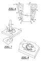
- Figure 7 is an orthogonal view of the nutplate of Figure 2 with adhesive material having been applied and with the nutplate and adhesive material being supported and drawn against a panel in alignment with a panel fastener hole by the nutplate positioning worm of Figure 2 ;
- Figure 8 is an orthogonal view of the nutplate of Figure 7 affixed to the panel of Figure 7 with the nutplate positioning worm of Figure 7 having been removed.
- an adhesive applicator device for applying uncured adhesive material 11 in a bead ring 13 surrounding a fastener hole 15 in a nutplate 17 is generally shown at 10 in Figures 1-6 .
- the device 10 may comprise a nozzle 12, with the nozzle 12 comprising a nozzle intake port 14, a nozzle outlet port 16, and a nozzle cavity 18 connecting and providing fluid communication between the intake 14 and outlet ports 16.
- the nozzle intake port 14 may be configured to receive uncured adhesive material 11 into the nozzle cavity 18 from a source 20 of uncured adhesive material 11.
- the outlet port 16 may have an annular shape configured to form an annular bead ring 13 of adhesive material 11 on a surface 22 onto which the nozzle 12 is dispensing adhesive material 11.
- the nozzle cavity 18 may comprise an annular flow path leading to the annular outlet port 16 and shaped to dispense adhesive material 11 axially through the outlet port 16.
- the nozzle 12 may also comprise inner and outer concentric walls 24, 26 that may at least partially define the cavity 18 and the annular flow path therebetween.
- the inner concentric wall 24 of the applicator nozzle 12 may protrude or extend axially beyond the outer concentric wall 26 to allow outward radial movement of uncured adhesive material 11 and to block inward radial encroachment of uncured adhesive material 11.
- the nozzle intake port 14 may be configured to receive the adhesive material 11 from the source 20 of uncured adhesive material, for example, an adhesive dispenser gun.
- the intake port 14, best shown in Figure 2 may be established by an intake fitting 28, which may be carried by the nozzle 12, through which the adhesive material 11 from the gun 20 may be received into the nozzle cavity 18.
- the intake fitting 28 may be configured to receive a mixing tip 30 of the adhesive dispenser gun 20 and to guide the adhesive material 11 from the mixing tip 30 of such a dispenser gun 20 into the annular flow path of the nozzle cavity 18 through the nozzle intake port 14.
- the intake fitting 28 may be oriented such that the uncured adhesive material 11 is received into the nozzle cavity 18 in a radially inward direction generally perpendicular to the annular flow path.
- the dispenser gun 20 may be a precision sealant dispensing system (PSDS) having pulsed volume control and configured such that a single trigger pull of the adhesive dispenser gun 20 will deliver an amount of uncured adhesive material 11 equal to a desired annular adhesive material bead volume.
- PSDS precision sealant dispensing system
- the device 10 may be configured to apply the uncured adhesive material 11 in the bead ring 13 to a surface of a flange portion 21 of a nutplate 17 surrounding the fastener hole 15 of the nutplate 17.
- the nutplate 17 may be of any suitable type including, but not limited to, a type available from Click Bond, Inc. of Carson City, Nevada.
- the inner concentric wall 24 of the nozzle 12 may define an axial clearance hole 32 shaped and sized to removably receive a generally rod-shaped nutplate positioning worm 23 shown in Figures 2 , 4, and 5 .
- the positioning worm 23 may be configured to be received both in the nutplate fastener hole 15 and in a panel fastener hole 25 formed in a panel 27 (shown in Figures 7 and 8 ) to which the nutplate 17 is to be adhered.
- the positioning worm 23 may include an annular shoulder 29 configured to engage the nutplate 17 and allow an installer to draw and hold the nutplate 17 against the panel 27 with the uncured bead ring 13 sandwiched between, while maintaining the nutplate 17 in concentric alignment with the panel fastener hole 25 as shown in Figure 7 . As shown in Figure 8 , the nutplate positioning worm 23 may be removed once the nutplate 17 has been successfully positioned against and adhered to the panel 27.
- the adhesive material bead ring 13 may be applied, as shown in Figure 5 , while the inner wall 24 blocks the uncured adhesive material 11 from flowing radially inward and prevents the uncured adhesive material 11 from entering and migrating along the nutplate fastener hole 15 between the fastener hole 15 and the worm 23 into locations where, once cured, the adhesive material 11 would limit movement between a floating portion of the nutplate 17 and the nutplate flange 21.
- the inner and outer concentric walls 24, 26 of the nozzle 12 may be shaped and positioned such that the nozzle cavity 18, and thus the annular flow path tapers in cross-sectional area in a flow direction 31 of adhesive material 11 along the annular flow path from an upper portion of the nozzle 12 to a lower portion of the nozzle 12.
- an axially lower portion 36 of the inner wall 24 may have an inverted frusto-conical radially outwardly-facing surface 38
- the outer wall 26 may have an inverted frusto-conical radially inwardly-facing surface 40 angled and positioned such that a lower portion 41 of the outer wall 26 is disposed generally parallel to, radially opposite, and spaced from the radially outer-facing surface 38 of the lower portion 36 of the inner wall 24.
- the smaller cross-sectional area of the annular flow path between the lower portions 36, 41 of the inner and outer concentric walls 24, 26; relative to the larger cross-sectional area of the annular flow path in the upper portion of the nozzle 12, causes the adhesive material 11 to flow around the nozzle 12 before being forced downward into and through the lower portions 36, 41 of the nozzle 12.
- the nozzle 12 may also include an annular upper end wall 42 capping the inner and outer concentric walls 24, 26 and an axially upper portion 44 of the inner concentric wall 24, which may extend from a radially inner periphery of the annular upper end wall 42 to an upper end of the axially lower portion 36 of the inner concentric wall 24.
- the axially upper portion 44 of the inner concentric wall 24 may have a generally cylindrical radially outward-facing surface 45.
- the nozzle 12 may include four circumferentially spaced stiffening ribs 46 that extend between the inner and outer concentric walls 24, 26. These circumferentially spaced ribs 46 may be integrally formed as a single unitary piece with the inner and outer concentric walls 24, 26 as is best shown in Figure 6 .
- the ribs 46 help to maintain a consistent adhesive material bead application by resisting radially outward flexing of the outer concentric wall 26 that might otherwise result from high pressure adhesive material flow through the nozzle 12.
- the ribs 46 may be thin enough to allow adhesive material to flow around them through intercostal spaces 47 defined by the ribs 46 and shown in Figure 3 .
- An adhesive application device constructed as described above, guides the application of a carefully metered adhesive material bead on a surface in a circumferentially continuous bead of uniform shape, size, and volume centered around a hole in the surface, while preventing the sealant from contaminating the hole.
Landscapes
- Engineering & Computer Science (AREA)
- Mechanical Engineering (AREA)
- Physics & Mathematics (AREA)
- Geometry (AREA)
- Coating Apparatus (AREA)
Abstract
Description
- This application relates generally to a method and device for applying an annular bead of adhesive material to a surface.
- Manufacturing processes in many fields require large numbers of extremely precise and consistent applications of adhesive material. For example, the preparation of thousands of holes commonly formed in aircraft skin panels to receive skin panel fasteners includes the mounting of thousands of nutplates in alignment with the respective skin panel fastener holes. To affix each nutplate, it is known to apply an annular bead of adhesive material either to a flange portion of the nutplate around a fastener hole in the nutplate, or to a skin panel to which the nutplate is to be affixed, around a corresponding skin panel fastener hole. The nutplate is then applied to the skin panel with the nutplate fastener hole aligned with the skin panel fastener hole and the annular bead of adhesive material sandwiched between the nutplate flange and the skin panel. In either case, the annular bead of adhesive material must be applied consistently in sufficient quantity and with sufficient surface area to securely attach the nutplate to the skin panel without flowing into and migrating along the nutplate fastener hole and between the flange and a floating element of the nutplate. Curing of adhesive material between a flange and floating element of a nutplate can jam or otherwise impede proper functioning of the nutplate. Current adhesive material application techniques rely on installer skill to accomplish the task of adhesive material application, with the inevitable result being that many nutplates are either insufficiently attached (resulting in failure of a subsequent push test, and requiring reinstallation), or are rendered inoperable due to adhesive contamination and must be replaced.
- An adhesive applicator device is provided for applying uncured adhesive material in a bead ring to a surface. The device may include a nozzle comprising a nozzle intake port, a nozzle outlet port, and a nozzle cavity connecting and providing fluid communication between the inlet and outlet ports. The nozzle intake port may be configured to receive uncured adhesive material into the nozzle cavity from a source of uncured adhesive material. The outlet port may have an annular shape configured to form an annular bead of adhesive material on a surface onto which the nozzle is dispensing adhesive material. The nozzle cavity may comprise an annular flow path that leads to the annular outlet port and is shaped to dispense adhesive material axially through the outlet port. The nozzle may also comprise inner and outer concentric walls that at least partially define the annular flow path therebetween. The inner concentric wall of the applicator nozzle may extend axially beyond the outer concentric wall to allow outward radial movement of uncured adhesive material and to block inward radial encroachment of uncured adhesive material.
- Also provided is an adhesive applicator device that may include a nozzle comprising a nozzle intake port, a nozzle outlet port, and a nozzle cavity connecting and providing fluid communication between the inlet and outlet ports; the nozzle intake port make be configured to receive uncured adhesive material into the nozzle cavity from a source ofuncured adhesive material, the outlet port may have an annular shape configured to form an annular bead of adhesive material on a surface onto which the nozzle is dispensing adhesive material, the nozzle cavity may comprise an annular flow path that leads to the annular outlet port and is shaped to dispense adhesive material axially through the outlet port, and the nozzle may comprise inner and outer concentric walls that at least partially define the annular flow path therebetween, and the inner and outer concentric walls may be shaped and positioned such that the annular flow path tapers in cross-sectional area in a flow direction of adhesive material along the annular flow path.
- These and other features and advantages will become apparent to those skilled in the art in connection with the following detailed description and drawings of one or more embodiments of the invention, in which:
-
Figure 1 is a perspective view of an adhesive applicator device carried by an adhesive dispenser gun; -
Figure 2 is a fragmentary cross-sectional side view of the adhesive applicator device and dispenser gun ofFigure 1 being held in coaxial alignment with a fastener hole of a nutplate by a nutplate positioning worm while applying adhesive material to a flange of the nutplate; -
Figure 3 is a top view of the adhesive applicator device ofFigure 1 ; -
Figure 4 is a fragmentary exploded perspective view of the adhesive applicator device, dispenser gun barrel, nutplate, and nutplate alignment worm ofFigure 2 ; -
Figure 5 is an enlarged perspective fragmentary view of the adhesive applicator device, dispenser gun barrel, nutplate, and nutplate alignment worm ofFigure 4 showing the adhesive applicator device applying a bead of adhesive material to a flange portion of the nutplate while being held in alignment by the nutplate alignment worm; -
Figure 6 is a cross-sectional view of the adhesive applicator device ofFigure 3 taken along line 5-5 ofFigure 3 ; -
Figure 7 is an orthogonal view of the nutplate ofFigure 2 with adhesive material having been applied and with the nutplate and adhesive material being supported and drawn against a panel in alignment with a panel fastener hole by the nutplate positioning worm ofFigure 2 ; and -
Figure 8 is an orthogonal view of the nutplate ofFigure 7 affixed to the panel ofFigure 7 with the nutplate positioning worm ofFigure 7 having been removed. - An adhesive applicator device for applying uncured adhesive material 11 in a
bead ring 13 surrounding afastener hole 15 in anutplate 17 is generally shown at 10 inFigures 1-6 . As best shown inFigure 2 , thedevice 10 may comprise anozzle 12, with thenozzle 12 comprising anozzle intake port 14, anozzle outlet port 16, and anozzle cavity 18 connecting and providing fluid communication between theintake 14 andoutlet ports 16. Thenozzle intake port 14 may be configured to receive uncured adhesive material 11 into thenozzle cavity 18 from asource 20 of uncured adhesive material 11. Theoutlet port 16 may have an annular shape configured to form anannular bead ring 13 of adhesive material 11 on a surface 22 onto which thenozzle 12 is dispensing adhesive material 11. Thenozzle cavity 18 may comprise an annular flow path leading to theannular outlet port 16 and shaped to dispense adhesive material 11 axially through theoutlet port 16. Thenozzle 12 may also comprise inner and outerconcentric walls cavity 18 and the annular flow path therebetween. The innerconcentric wall 24 of theapplicator nozzle 12 may protrude or extend axially beyond the outerconcentric wall 26 to allow outward radial movement of uncured adhesive material 11 and to block inward radial encroachment of uncured adhesive material 11. - As shown in
Figure 1 , thenozzle intake port 14 may be configured to receive the adhesive material 11 from thesource 20 of uncured adhesive material, for example, an adhesive dispenser gun. Theintake port 14, best shown inFigure 2 , may be established by an intake fitting 28, which may be carried by thenozzle 12, through which the adhesive material 11 from thegun 20 may be received into thenozzle cavity 18. The intake fitting 28 may be configured to receive amixing tip 30 of theadhesive dispenser gun 20 and to guide the adhesive material 11 from themixing tip 30 of such adispenser gun 20 into the annular flow path of thenozzle cavity 18 through thenozzle intake port 14. The intake fitting 28 may be oriented such that the uncured adhesive material 11 is received into thenozzle cavity 18 in a radially inward direction generally perpendicular to the annular flow path. To ensure consistent adhesive material flow, thedispenser gun 20 may be a precision sealant dispensing system (PSDS) having pulsed volume control and configured such that a single trigger pull of theadhesive dispenser gun 20 will deliver an amount of uncured adhesive material 11 equal to a desired annular adhesive material bead volume. - As shown in
Figures 2 ,4, and 5 , thedevice 10 may be configured to apply the uncured adhesive material 11 in thebead ring 13 to a surface of a flange portion 21 of anutplate 17 surrounding thefastener hole 15 of thenutplate 17. Thenutplate 17 may be of any suitable type including, but not limited to, a type available from Click Bond, Inc. of Carson City, Nevada. - As best shown in
Figure 3 , the innerconcentric wall 24 of thenozzle 12 may define anaxial clearance hole 32 shaped and sized to removably receive a generally rod-shapednutplate positioning worm 23 shown inFigures 2 ,4, and 5 . Thepositioning worm 23 may be configured to be received both in thenutplate fastener hole 15 and in apanel fastener hole 25 formed in a panel 27 (shown inFigures 7 and 8 ) to which thenutplate 17 is to be adhered. Thepositioning worm 23 may include anannular shoulder 29 configured to engage thenutplate 17 and allow an installer to draw and hold thenutplate 17 against thepanel 27 with theuncured bead ring 13 sandwiched between, while maintaining thenutplate 17 in concentric alignment with thepanel fastener hole 25 as shown inFigure 7 . As shown inFigure 8 , thenutplate positioning worm 23 may be removed once thenutplate 17 has been successfully positioned against and adhered to thepanel 27. - When the
applicator nozzle 12 is positioned against the nutplate flange 21, as shown inFigure 5 , with theapplicator clearance hole 32 positioned concentrically with thenutplate fastener hole 15, aforward end 34 of theinner wall 24 of theapplicator device 10 may be seated against the nutplate flange 21 as shown inFigure 2 . Because theinner wall 24 extends axially beyond theouter wall 26, the adhesivematerial bead ring 13 may be applied, as shown inFigure 5 , while theinner wall 24 blocks the uncured adhesive material 11 from flowing radially inward and prevents the uncured adhesive material 11 from entering and migrating along thenutplate fastener hole 15 between thefastener hole 15 and theworm 23 into locations where, once cured, the adhesive material 11 would limit movement between a floating portion of thenutplate 17 and the nutplate flange 21. - As best shown in
Figures 2 and6 , the inner and outerconcentric walls nozzle 12 may be shaped and positioned such that thenozzle cavity 18, and thus the annular flow path tapers in cross-sectional area in aflow direction 31 of adhesive material 11 along the annular flow path from an upper portion of thenozzle 12 to a lower portion of thenozzle 12. In other words, an axiallylower portion 36 of theinner wall 24 may have an inverted frusto-conical radially outwardly-facingsurface 38, and theouter wall 26 may have an inverted frusto-conical radially inwardly-facingsurface 40 angled and positioned such that alower portion 41 of theouter wall 26 is disposed generally parallel to, radially opposite, and spaced from the radially outer-facingsurface 38 of thelower portion 36 of theinner wall 24. The smaller cross-sectional area of the annular flow path between thelower portions concentric walls nozzle 12, causes the adhesive material 11 to flow around thenozzle 12 before being forced downward into and through thelower portions nozzle 12. Thenozzle 12 may also include an annularupper end wall 42 capping the inner and outerconcentric walls upper portion 44 of the innerconcentric wall 24, which may extend from a radially inner periphery of the annularupper end wall 42 to an upper end of the axiallylower portion 36 of the innerconcentric wall 24. The axiallyupper portion 44 of the innerconcentric wall 24 may have a generally cylindrical radially outward-facingsurface 45. - As best shown in
Figures 3 and6 , thenozzle 12 may include four circumferentially spacedstiffening ribs 46 that extend between the inner and outerconcentric walls ribs 46 may be integrally formed as a single unitary piece with the inner and outerconcentric walls Figure 6 . Theribs 46 help to maintain a consistent adhesive material bead application by resisting radially outward flexing of the outerconcentric wall 26 that might otherwise result from high pressure adhesive material flow through thenozzle 12. Theribs 46 may be thin enough to allow adhesive material to flow around them through intercostal spaces 47 defined by theribs 46 and shown inFigure 3 . - An adhesive application device constructed as described above, guides the application of a carefully metered adhesive material bead on a surface in a circumferentially continuous bead of uniform shape, size, and volume centered around a hole in the surface, while preventing the sealant from contaminating the hole.
- This description, rather than describing limitations of an invention, only illustrates an embodiment of the invention recited in the claims. The language of this description is therefore exclusively descriptive and is non-limiting. Obviously, it's possible to modify this invention from what the description teaches. Within the scope of the claims, one may practice the invention other than as described above.
Claims (14)
- An adhesive applicator device for applying adhesive material in a bead ring to a surface, the device comprising:a nozzle comprising a nozzle intake port, a nozzle outlet port, and a nozzle cavity connecting and providing fluid communication between the inlet and outlet ports;the outlet port having an annular shape configured to form an annular bead of adhesive material on a surface onto which the nozzle dispenses adhesive material;the nozzle cavity comprising an annular flow path leading to the annular outlet port and shaped to dispense adhesive material through the outlet port axially; andthe nozzle comprising inner and outer concentric walls defining the annular flow path therebetween, the inner concentric wall extending axially beyond the outer concentric wall to allow outward radial movement of adhesive material and to block inward radial encroachment of adhesive material.
- An adhesive applicator device as defined in claim 1 in which the intake port is configured to receive adhesive material from an adhesive dispenser into the annular flow path.
- An adhesive applicator device as defined in claim 1 or 2 in which an intake fitting is carried by the nozzle and is configured to receive a mixing tip of an adhesive dispenser gun and to guide adhesive material from the mixing tip of the dispenser gun into the nozzle cavity through the nozzle intake port.
- An adhesive applicator device as defined in claim 3 in which the intake fitting is oriented such that uncured adhesive material is received into the nozzle cavity in a radially inward direction generally perpendicular to the annular flow path.
- An adhesive applicator device as defined in any one of the preceding claims in which the inner concentric wall defines an axial clearance hole for removably receiving a nutplate positioning worm.
- An adhesive applicator device as defined in any one of the preceding claims, wherein the inner and outer concentric walls are shaped and positioned such that the annular flow path tapers in cross-sectional area in a flow direction of adhesive material along the annular flow path.
- An adhesive applicator device for applying uncured adhesive material in a bead ring to a panel surface, the device comprising:a nozzle comprising a nozzle intake port, a nozzle outlet port, and a nozzle cavity connecting and providing fluid communication between the inlet and outlet ports;the nozzle intake port being configured to receive uncured adhesive material into the nozzle cavity from a source of uncured adhesive material;the outlet port having an annular shape configured to form an annular bead of adhesive material on a surface onto which the nozzle dispenses adhesive material;the nozzle cavity comprising an annular flow path leading to the annular outlet port and shaped to dispense the adhesive material through the outlet port axially; andthe nozzle including inner and outer concentric walls that at least partially define the annular flow path and that are shaped and positioned such that the annular flow path tapers in cross-sectional area in a flow direction of adhesive material along the annular flow path.
- An adhesive applicator device as defined in any one of the preceding claims in which the nozzle includes an annular upper end wall capping the inner and outer concentric walls.
- An adhesive applicator device as defined in any one of the preceding claims in which:an axially lower portion of the inner wall has an inverted frusto-conical radially outwardly-facing surface; andthe outer wall has an inverted frusto-conical radially inwardly-facing surface angled and positioned such that a lower portion of the outer wall is disposed generally parallel to, radially opposite, and spaced from the radially outer-facing surface of the lower portion of the inner wall.
- An adhesive applicator device as defined in claim 9 in which an axially upper portion of the inner wall, which extends from a radially inner periphery of the annular upper end wall to an upper end of the axially lower portion of the inner concentric wall, has a generally cylindrical radially outwardly-facing surface.
- An adhesive applicator device as defined in any one of the preceding claims in which the inner wall of the nozzle extends axially beyond the outer wall so that, by engaging a forward end of the inner wall against a nutplate surface surrounding a fastener hole, the inner wall is positioned to block adhesive material from moving radially inward toward the fastener hole during bead application.
- An adhesive applicator device as defined in any one of claims 7 to 11, in which the inner concentric wall defines an axial clearance hole for removably receiving a nutplate positioning worm.
- An adhesive applicator device as defined in any one of the preceding claims in which the nozzle further includes a plurality of circumferentially spaced ribs that extend between the inner and outer concentric walls.
- An adhesive applicator device as defined in claim 13 in which the plurality of circumferentially spaced ribs is integrally formed with the inner and outer concentric walls as a single unitary piece.
Applications Claiming Priority (1)
| Application Number | Priority Date | Filing Date | Title |
|---|---|---|---|
| US13/683,470 US9266140B2 (en) | 2012-11-21 | 2012-11-21 | Annular adhesive bead application |
Publications (2)
| Publication Number | Publication Date |
|---|---|
| EP2740540A1 true EP2740540A1 (en) | 2014-06-11 |
| EP2740540B1 EP2740540B1 (en) | 2017-10-18 |
Family
ID=49596190
Family Applications (1)
| Application Number | Title | Priority Date | Filing Date |
|---|---|---|---|
| EP13193709.6A Active EP2740540B1 (en) | 2012-11-21 | 2013-11-20 | Annular adhesive bead application |
Country Status (3)
| Country | Link |
|---|---|
| US (1) | US9266140B2 (en) |
| EP (1) | EP2740540B1 (en) |
| JP (1) | JP6271961B2 (en) |
Cited By (1)
| Publication number | Priority date | Publication date | Assignee | Title |
|---|---|---|---|---|
| GB2579229A (en) * | 2018-11-26 | 2020-06-17 | Airbus Operations Ltd | Spark containment cap |
Families Citing this family (2)
| Publication number | Priority date | Publication date | Assignee | Title |
|---|---|---|---|---|
| US9578949B2 (en) * | 2013-06-24 | 2017-02-28 | HCT Group Holdings Limited | Dispenser with threaded tip/dispenser with removable cap |
| US9968962B2 (en) * | 2015-03-19 | 2018-05-15 | The Boeing Company | Material applicator comprising a surface interface guide forming a continuous ring shaped flow channel with an unobstructive guding assembly therein |
Citations (5)
| Publication number | Priority date | Publication date | Assignee | Title |
|---|---|---|---|---|
| GB1399924A (en) * | 1971-09-04 | 1975-07-02 | Itw Ateco Gmbh | Sealing holes in panels |
| WO1983001747A1 (en) * | 1981-11-18 | 1983-05-26 | Hans Moss | A blowing nozzle for silent outflow of gas |
| US4385728A (en) * | 1981-01-30 | 1983-05-31 | Vortec Corporation | Flow-amplifying nozzle |
| FR2606674A1 (en) * | 1986-11-18 | 1988-05-20 | Rasselstein Ag | DEVICE FOR THE APPLICATION OF A VERY VISCOUS SEALING MATERIAL IN THE FORM OF A RING ON AN ESSENTIALLY FLAT SURFACE, IN PARTICULAR, A BOX COVER |
| GB2470488A (en) * | 2009-05-22 | 2010-11-24 | Stjohn Van Niftrik | Annular applicator |
Family Cites Families (10)
| Publication number | Priority date | Publication date | Assignee | Title |
|---|---|---|---|---|
| GB1042714A (en) | 1964-04-06 | 1966-09-14 | Dca Food Ind | Method and apparatus for forming fried ring-shaped comestibles |
| JPS5139905B2 (en) * | 1973-05-14 | 1976-10-30 | ||
| US4429658A (en) | 1981-08-10 | 1984-02-07 | The Boeing Company | Sealant applicator for rivets |
| US5013391A (en) * | 1989-06-12 | 1991-05-07 | Physical Systems, Inc. | Adhesive nutplate assembly for mounting |
| US5605541A (en) | 1994-12-07 | 1997-02-25 | E. R. Squibb And Sons, Inc. | Fibrin sealant applicatoor |
| JP2001246304A (en) * | 2000-03-09 | 2001-09-11 | Koojiitekku Kk | High viscous material applying nozzle and nozzle engaging member |
| US6981611B2 (en) * | 2003-09-09 | 2006-01-03 | Ronald Scott Carruth | Tip for a caulking gun |
| US7845536B2 (en) | 2004-10-18 | 2010-12-07 | Tyco Healthcare Group Lp | Annular adhesive structure |
| GB2477223A (en) | 2006-11-28 | 2011-07-27 | Optinose As | Nasal delivery system with a replaceable nosepiece unit |
| US8616868B2 (en) * | 2011-02-28 | 2013-12-31 | Physical Systems, Inc. | Sealant mold fixture for a domed cap |
-
2012
- 2012-11-21 US US13/683,470 patent/US9266140B2/en active Active
-
2013
- 2013-11-19 JP JP2013239207A patent/JP6271961B2/en active Active
- 2013-11-20 EP EP13193709.6A patent/EP2740540B1/en active Active
Patent Citations (5)
| Publication number | Priority date | Publication date | Assignee | Title |
|---|---|---|---|---|
| GB1399924A (en) * | 1971-09-04 | 1975-07-02 | Itw Ateco Gmbh | Sealing holes in panels |
| US4385728A (en) * | 1981-01-30 | 1983-05-31 | Vortec Corporation | Flow-amplifying nozzle |
| WO1983001747A1 (en) * | 1981-11-18 | 1983-05-26 | Hans Moss | A blowing nozzle for silent outflow of gas |
| FR2606674A1 (en) * | 1986-11-18 | 1988-05-20 | Rasselstein Ag | DEVICE FOR THE APPLICATION OF A VERY VISCOUS SEALING MATERIAL IN THE FORM OF A RING ON AN ESSENTIALLY FLAT SURFACE, IN PARTICULAR, A BOX COVER |
| GB2470488A (en) * | 2009-05-22 | 2010-11-24 | Stjohn Van Niftrik | Annular applicator |
Cited By (2)
| Publication number | Priority date | Publication date | Assignee | Title |
|---|---|---|---|---|
| GB2579229A (en) * | 2018-11-26 | 2020-06-17 | Airbus Operations Ltd | Spark containment cap |
| US11731783B2 (en) | 2018-11-26 | 2023-08-22 | Airbus Operations Limited | Spark containment cap |
Also Published As
| Publication number | Publication date |
|---|---|
| US20140138413A1 (en) | 2014-05-22 |
| EP2740540B1 (en) | 2017-10-18 |
| JP6271961B2 (en) | 2018-01-31 |
| JP2014100705A (en) | 2014-06-05 |
| US9266140B2 (en) | 2016-02-23 |
Similar Documents
| Publication | Publication Date | Title |
|---|---|---|
| US8881950B2 (en) | Multiple component dispensing cartridge, mixing nozzle and method for reducing contact between fluids | |
| EP2740540B1 (en) | Annular adhesive bead application | |
| EP3059170A1 (en) | Cap with injected sealant | |
| US8460235B2 (en) | Dispensing assembly for two components with double syringe and mixer | |
| US7232273B2 (en) | Method and apparatus for applying sealant to fasteners | |
| US8562888B2 (en) | Portable sealant dispense system | |
| EP2828005B1 (en) | A flow restrictor | |
| US20140263480A1 (en) | Countersink sealant applicator | |
| US9656287B2 (en) | Handheld valve dispensers and related methods | |
| EP2982440B1 (en) | Attachment for liquid injection and liquid injection method | |
| KR20170038006A (en) | Syringe attachment/detachment mechanism and device provided with mechanism | |
| US10480700B2 (en) | Nozzle arrangement for flowable substances | |
| US10471461B2 (en) | Liquid dispensing module | |
| US20160325295A1 (en) | Coating Machine | |
| EP2817102B1 (en) | Dispenser comprising actuating piston and outlet check valve | |
| KR102383801B1 (en) | Mixing valve assembly having an atomizing spray tip | |
| ES2917416T3 (en) | Procedure for the automatic application of a viscous product on a rivet head | |
| EP2788823B1 (en) | Capillary flow control system for fluid indicator | |
| EP3784167B1 (en) | Dispenser assembly | |
| US20220331834A1 (en) | Dispense tips and methods of manufacturing the same | |
| KR102544897B1 (en) | Long flow path member, plastic container, and viscous-liquid discharge device | |
| WO2020054113A1 (en) | Viscous material coating apparatus | |
| US10724568B2 (en) | Sealant application system | |
| US20120294780A1 (en) | Drop-in nozzle | |
| EP3656679A1 (en) | Spark containment cap |
Legal Events
| Date | Code | Title | Description |
|---|---|---|---|
| PUAI | Public reference made under article 153(3) epc to a published international application that has entered the european phase |
Free format text: ORIGINAL CODE: 0009012 |
|
| 17P | Request for examination filed |
Effective date: 20131120 |
|
| AK | Designated contracting states |
Kind code of ref document: A1 Designated state(s): AL AT BE BG CH CY CZ DE DK EE ES FI FR GB GR HR HU IE IS IT LI LT LU LV MC MK MT NL NO PL PT RO RS SE SI SK SM TR |
|
| AX | Request for extension of the european patent |
Extension state: BA ME |
|
| R17P | Request for examination filed (corrected) |
Effective date: 20141210 |
|
| RBV | Designated contracting states (corrected) |
Designated state(s): AL AT BE BG CH CY CZ DE DK EE ES FI FR GB GR HR HU IE IS IT LI LT LU LV MC MK MT NL NO PL PT RO RS SE SI SK SM TR |
|
| 17Q | First examination report despatched |
Effective date: 20160722 |
|
| STAA | Information on the status of an ep patent application or granted ep patent |
Free format text: STATUS: EXAMINATION IS IN PROGRESS |
|
| GRAP | Despatch of communication of intention to grant a patent |
Free format text: ORIGINAL CODE: EPIDOSNIGR1 |
|
| STAA | Information on the status of an ep patent application or granted ep patent |
Free format text: STATUS: GRANT OF PATENT IS INTENDED |
|
| INTG | Intention to grant announced |
Effective date: 20170622 |
|
| GRAS | Grant fee paid |
Free format text: ORIGINAL CODE: EPIDOSNIGR3 |
|
| GRAA | (expected) grant |
Free format text: ORIGINAL CODE: 0009210 |
|
| STAA | Information on the status of an ep patent application or granted ep patent |
Free format text: STATUS: THE PATENT HAS BEEN GRANTED |
|
| AK | Designated contracting states |
Kind code of ref document: B1 Designated state(s): AL AT BE BG CH CY CZ DE DK EE ES FI FR GB GR HR HU IE IS IT LI LT LU LV MC MK MT NL NO PL PT RO RS SE SI SK SM TR |
|
| REG | Reference to a national code |
Ref country code: GB Ref legal event code: FG4D |
|
| REG | Reference to a national code |
Ref country code: CH Ref legal event code: EP |
|
| REG | Reference to a national code |
Ref country code: AT Ref legal event code: REF Ref document number: 937477 Country of ref document: AT Kind code of ref document: T Effective date: 20171115 Ref country code: IE Ref legal event code: FG4D |
|
| REG | Reference to a national code |
Ref country code: FR Ref legal event code: PLFP Year of fee payment: 5 |
|
| REG | Reference to a national code |
Ref country code: DE Ref legal event code: R096 Ref document number: 602013028036 Country of ref document: DE |
|
| REG | Reference to a national code |
Ref country code: NL Ref legal event code: MP Effective date: 20171018 |
|
| REG | Reference to a national code |
Ref country code: LT Ref legal event code: MG4D |
|
| REG | Reference to a national code |
Ref country code: AT Ref legal event code: MK05 Ref document number: 937477 Country of ref document: AT Kind code of ref document: T Effective date: 20171018 |
|
| PG25 | Lapsed in a contracting state [announced via postgrant information from national office to epo] |
Ref country code: NL Free format text: LAPSE BECAUSE OF FAILURE TO SUBMIT A TRANSLATION OF THE DESCRIPTION OR TO PAY THE FEE WITHIN THE PRESCRIBED TIME-LIMIT Effective date: 20171018 |
|
| PG25 | Lapsed in a contracting state [announced via postgrant information from national office to epo] |
Ref country code: LT Free format text: LAPSE BECAUSE OF FAILURE TO SUBMIT A TRANSLATION OF THE DESCRIPTION OR TO PAY THE FEE WITHIN THE PRESCRIBED TIME-LIMIT Effective date: 20171018 Ref country code: FI Free format text: LAPSE BECAUSE OF FAILURE TO SUBMIT A TRANSLATION OF THE DESCRIPTION OR TO PAY THE FEE WITHIN THE PRESCRIBED TIME-LIMIT Effective date: 20171018 Ref country code: NO Free format text: LAPSE BECAUSE OF FAILURE TO SUBMIT A TRANSLATION OF THE DESCRIPTION OR TO PAY THE FEE WITHIN THE PRESCRIBED TIME-LIMIT Effective date: 20180118 Ref country code: ES Free format text: LAPSE BECAUSE OF FAILURE TO SUBMIT A TRANSLATION OF THE DESCRIPTION OR TO PAY THE FEE WITHIN THE PRESCRIBED TIME-LIMIT Effective date: 20171018 Ref country code: SE Free format text: LAPSE BECAUSE OF FAILURE TO SUBMIT A TRANSLATION OF THE DESCRIPTION OR TO PAY THE FEE WITHIN THE PRESCRIBED TIME-LIMIT Effective date: 20171018 |
|
| PG25 | Lapsed in a contracting state [announced via postgrant information from national office to epo] |
Ref country code: LV Free format text: LAPSE BECAUSE OF FAILURE TO SUBMIT A TRANSLATION OF THE DESCRIPTION OR TO PAY THE FEE WITHIN THE PRESCRIBED TIME-LIMIT Effective date: 20171018 Ref country code: RS Free format text: LAPSE BECAUSE OF FAILURE TO SUBMIT A TRANSLATION OF THE DESCRIPTION OR TO PAY THE FEE WITHIN THE PRESCRIBED TIME-LIMIT Effective date: 20171018 Ref country code: HR Free format text: LAPSE BECAUSE OF FAILURE TO SUBMIT A TRANSLATION OF THE DESCRIPTION OR TO PAY THE FEE WITHIN THE PRESCRIBED TIME-LIMIT Effective date: 20171018 Ref country code: AT Free format text: LAPSE BECAUSE OF FAILURE TO SUBMIT A TRANSLATION OF THE DESCRIPTION OR TO PAY THE FEE WITHIN THE PRESCRIBED TIME-LIMIT Effective date: 20171018 Ref country code: GR Free format text: LAPSE BECAUSE OF FAILURE TO SUBMIT A TRANSLATION OF THE DESCRIPTION OR TO PAY THE FEE WITHIN THE PRESCRIBED TIME-LIMIT Effective date: 20180119 Ref country code: BG Free format text: LAPSE BECAUSE OF FAILURE TO SUBMIT A TRANSLATION OF THE DESCRIPTION OR TO PAY THE FEE WITHIN THE PRESCRIBED TIME-LIMIT Effective date: 20180118 Ref country code: IS Free format text: LAPSE BECAUSE OF FAILURE TO SUBMIT A TRANSLATION OF THE DESCRIPTION OR TO PAY THE FEE WITHIN THE PRESCRIBED TIME-LIMIT Effective date: 20180218 |
|
| REG | Reference to a national code |
Ref country code: DE Ref legal event code: R097 Ref document number: 602013028036 Country of ref document: DE |
|
| PG25 | Lapsed in a contracting state [announced via postgrant information from national office to epo] |
Ref country code: MC Free format text: LAPSE BECAUSE OF FAILURE TO SUBMIT A TRANSLATION OF THE DESCRIPTION OR TO PAY THE FEE WITHIN THE PRESCRIBED TIME-LIMIT Effective date: 20171018 Ref country code: SK Free format text: LAPSE BECAUSE OF FAILURE TO SUBMIT A TRANSLATION OF THE DESCRIPTION OR TO PAY THE FEE WITHIN THE PRESCRIBED TIME-LIMIT Effective date: 20171018 Ref country code: CZ Free format text: LAPSE BECAUSE OF FAILURE TO SUBMIT A TRANSLATION OF THE DESCRIPTION OR TO PAY THE FEE WITHIN THE PRESCRIBED TIME-LIMIT Effective date: 20171018 Ref country code: LI Free format text: LAPSE BECAUSE OF NON-PAYMENT OF DUE FEES Effective date: 20171130 Ref country code: CH Free format text: LAPSE BECAUSE OF NON-PAYMENT OF DUE FEES Effective date: 20171130 Ref country code: EE Free format text: LAPSE BECAUSE OF FAILURE TO SUBMIT A TRANSLATION OF THE DESCRIPTION OR TO PAY THE FEE WITHIN THE PRESCRIBED TIME-LIMIT Effective date: 20171018 Ref country code: DK Free format text: LAPSE BECAUSE OF FAILURE TO SUBMIT A TRANSLATION OF THE DESCRIPTION OR TO PAY THE FEE WITHIN THE PRESCRIBED TIME-LIMIT Effective date: 20171018 |
|
| PLBE | No opposition filed within time limit |
Free format text: ORIGINAL CODE: 0009261 |
|
| STAA | Information on the status of an ep patent application or granted ep patent |
Free format text: STATUS: NO OPPOSITION FILED WITHIN TIME LIMIT |
|
| PG25 | Lapsed in a contracting state [announced via postgrant information from national office to epo] |
Ref country code: SM Free format text: LAPSE BECAUSE OF FAILURE TO SUBMIT A TRANSLATION OF THE DESCRIPTION OR TO PAY THE FEE WITHIN THE PRESCRIBED TIME-LIMIT Effective date: 20171018 Ref country code: RO Free format text: LAPSE BECAUSE OF FAILURE TO SUBMIT A TRANSLATION OF THE DESCRIPTION OR TO PAY THE FEE WITHIN THE PRESCRIBED TIME-LIMIT Effective date: 20171018 Ref country code: PL Free format text: LAPSE BECAUSE OF FAILURE TO SUBMIT A TRANSLATION OF THE DESCRIPTION OR TO PAY THE FEE WITHIN THE PRESCRIBED TIME-LIMIT Effective date: 20171018 Ref country code: LU Free format text: LAPSE BECAUSE OF NON-PAYMENT OF DUE FEES Effective date: 20171120 |
|
| REG | Reference to a national code |
Ref country code: BE Ref legal event code: MM Effective date: 20171130 |
|
| REG | Reference to a national code |
Ref country code: IE Ref legal event code: MM4A |
|
| 26N | No opposition filed |
Effective date: 20180719 |
|
| PG25 | Lapsed in a contracting state [announced via postgrant information from national office to epo] |
Ref country code: MT Free format text: LAPSE BECAUSE OF NON-PAYMENT OF DUE FEES Effective date: 20171120 |
|
| PG25 | Lapsed in a contracting state [announced via postgrant information from national office to epo] |
Ref country code: IE Free format text: LAPSE BECAUSE OF NON-PAYMENT OF DUE FEES Effective date: 20171120 |
|
| PG25 | Lapsed in a contracting state [announced via postgrant information from national office to epo] |
Ref country code: SI Free format text: LAPSE BECAUSE OF FAILURE TO SUBMIT A TRANSLATION OF THE DESCRIPTION OR TO PAY THE FEE WITHIN THE PRESCRIBED TIME-LIMIT Effective date: 20171018 Ref country code: BE Free format text: LAPSE BECAUSE OF NON-PAYMENT OF DUE FEES Effective date: 20171130 |
|
| PG25 | Lapsed in a contracting state [announced via postgrant information from national office to epo] |
Ref country code: HU Free format text: LAPSE BECAUSE OF FAILURE TO SUBMIT A TRANSLATION OF THE DESCRIPTION OR TO PAY THE FEE WITHIN THE PRESCRIBED TIME-LIMIT; INVALID AB INITIO Effective date: 20131120 |
|
| PG25 | Lapsed in a contracting state [announced via postgrant information from national office to epo] |
Ref country code: CY Free format text: LAPSE BECAUSE OF NON-PAYMENT OF DUE FEES Effective date: 20171018 |
|
| PG25 | Lapsed in a contracting state [announced via postgrant information from national office to epo] |
Ref country code: MK Free format text: LAPSE BECAUSE OF FAILURE TO SUBMIT A TRANSLATION OF THE DESCRIPTION OR TO PAY THE FEE WITHIN THE PRESCRIBED TIME-LIMIT Effective date: 20171018 |
|
| PG25 | Lapsed in a contracting state [announced via postgrant information from national office to epo] |
Ref country code: TR Free format text: LAPSE BECAUSE OF FAILURE TO SUBMIT A TRANSLATION OF THE DESCRIPTION OR TO PAY THE FEE WITHIN THE PRESCRIBED TIME-LIMIT Effective date: 20171018 |
|
| PG25 | Lapsed in a contracting state [announced via postgrant information from national office to epo] |
Ref country code: PT Free format text: LAPSE BECAUSE OF FAILURE TO SUBMIT A TRANSLATION OF THE DESCRIPTION OR TO PAY THE FEE WITHIN THE PRESCRIBED TIME-LIMIT Effective date: 20171018 |
|
| PG25 | Lapsed in a contracting state [announced via postgrant information from national office to epo] |
Ref country code: AL Free format text: LAPSE BECAUSE OF FAILURE TO SUBMIT A TRANSLATION OF THE DESCRIPTION OR TO PAY THE FEE WITHIN THE PRESCRIBED TIME-LIMIT Effective date: 20171018 |
|
| P01 | Opt-out of the competence of the unified patent court (upc) registered |
Effective date: 20230515 |
|
| PGFP | Annual fee paid to national office [announced via postgrant information from national office to epo] |
Ref country code: DE Payment date: 20251128 Year of fee payment: 13 |
|
| PGFP | Annual fee paid to national office [announced via postgrant information from national office to epo] |
Ref country code: GB Payment date: 20251127 Year of fee payment: 13 |
|
| PGFP | Annual fee paid to national office [announced via postgrant information from national office to epo] |
Ref country code: IT Payment date: 20251119 Year of fee payment: 13 |
|
| PGFP | Annual fee paid to national office [announced via postgrant information from national office to epo] |
Ref country code: FR Payment date: 20251125 Year of fee payment: 13 |