EP2738935A1 - Electric machine comprising an alternating current electric motor and an inverter - Google Patents
Electric machine comprising an alternating current electric motor and an inverter Download PDFInfo
- Publication number
- EP2738935A1 EP2738935A1 EP20130193243 EP13193243A EP2738935A1 EP 2738935 A1 EP2738935 A1 EP 2738935A1 EP 20130193243 EP20130193243 EP 20130193243 EP 13193243 A EP13193243 A EP 13193243A EP 2738935 A1 EP2738935 A1 EP 2738935A1
- Authority
- EP
- European Patent Office
- Prior art keywords
- semi
- winding
- inverter
- frequency
- alternating current
- Prior art date
- Legal status (The legal status is an assumption and is not a legal conclusion. Google has not performed a legal analysis and makes no representation as to the accuracy of the status listed.)
- Ceased
Links
Images


Classifications
-
- H—ELECTRICITY
- H02—GENERATION; CONVERSION OR DISTRIBUTION OF ELECTRIC POWER
- H02P—CONTROL OR REGULATION OF ELECTRIC MOTORS, ELECTRIC GENERATORS OR DYNAMO-ELECTRIC CONVERTERS; CONTROLLING TRANSFORMERS, REACTORS OR CHOKE COILS
- H02P25/00—Arrangements or methods for the control of AC motors characterised by the kind of AC motor or by structural details
- H02P25/16—Arrangements or methods for the control of AC motors characterised by the kind of AC motor or by structural details characterised by the circuit arrangement or by the kind of wiring
- H02P25/22—Multiple windings; Windings for more than three phases
-
- H—ELECTRICITY
- H02—GENERATION; CONVERSION OR DISTRIBUTION OF ELECTRIC POWER
- H02M—APPARATUS FOR CONVERSION BETWEEN AC AND AC, BETWEEN AC AND DC, OR BETWEEN DC AND DC, AND FOR USE WITH MAINS OR SIMILAR POWER SUPPLY SYSTEMS; CONVERSION OF DC OR AC INPUT POWER INTO SURGE OUTPUT POWER; CONTROL OR REGULATION THEREOF
- H02M7/00—Conversion of AC power input into DC power output; Conversion of DC power input into AC power output
- H02M7/42—Conversion of DC power input into AC power output without possibility of reversal
- H02M7/44—Conversion of DC power input into AC power output without possibility of reversal by static converters
- H02M7/48—Conversion of DC power input into AC power output without possibility of reversal by static converters using discharge tubes with control electrode or semiconductor devices with control electrode
- H02M7/53—Conversion of DC power input into AC power output without possibility of reversal by static converters using discharge tubes with control electrode or semiconductor devices with control electrode using devices of a triode or transistor type requiring continuous application of a control signal
- H02M7/537—Conversion of DC power input into AC power output without possibility of reversal by static converters using discharge tubes with control electrode or semiconductor devices with control electrode using devices of a triode or transistor type requiring continuous application of a control signal using semiconductor devices only, e.g. single switched pulse inverters
- H02M7/5387—Conversion of DC power input into AC power output without possibility of reversal by static converters using discharge tubes with control electrode or semiconductor devices with control electrode using devices of a triode or transistor type requiring continuous application of a control signal using semiconductor devices only, e.g. single switched pulse inverters in a bridge configuration
- H02M7/53871—Conversion of DC power input into AC power output without possibility of reversal by static converters using discharge tubes with control electrode or semiconductor devices with control electrode using devices of a triode or transistor type requiring continuous application of a control signal using semiconductor devices only, e.g. single switched pulse inverters in a bridge configuration with automatic control of output voltage or current
-
- H—ELECTRICITY
- H02—GENERATION; CONVERSION OR DISTRIBUTION OF ELECTRIC POWER
- H02P—CONTROL OR REGULATION OF ELECTRIC MOTORS, ELECTRIC GENERATORS OR DYNAMO-ELECTRIC CONVERTERS; CONTROLLING TRANSFORMERS, REACTORS OR CHOKE COILS
- H02P23/00—Arrangements or methods for the control of AC motors characterised by a control method other than vector control
- H02P23/28—Controlling the motor by varying the switching frequency of switches connected to a DC supply and the motor phases
-
- H—ELECTRICITY
- H02—GENERATION; CONVERSION OR DISTRIBUTION OF ELECTRIC POWER
- H02P—CONTROL OR REGULATION OF ELECTRIC MOTORS, ELECTRIC GENERATORS OR DYNAMO-ELECTRIC CONVERTERS; CONTROLLING TRANSFORMERS, REACTORS OR CHOKE COILS
- H02P27/00—Arrangements or methods for the control of AC motors characterised by the kind of supply voltage
- H02P27/04—Arrangements or methods for the control of AC motors characterised by the kind of supply voltage using variable-frequency supply voltage, e.g. inverter or converter supply voltage
- H02P27/06—Arrangements or methods for the control of AC motors characterised by the kind of supply voltage using variable-frequency supply voltage, e.g. inverter or converter supply voltage using DC to AC converters or inverters
- H02P27/08—Arrangements or methods for the control of AC motors characterised by the kind of supply voltage using variable-frequency supply voltage, e.g. inverter or converter supply voltage using DC to AC converters or inverters with pulse width modulation
-
- H—ELECTRICITY
- H02—GENERATION; CONVERSION OR DISTRIBUTION OF ELECTRIC POWER
- H02P—CONTROL OR REGULATION OF ELECTRIC MOTORS, ELECTRIC GENERATORS OR DYNAMO-ELECTRIC CONVERTERS; CONTROLLING TRANSFORMERS, REACTORS OR CHOKE COILS
- H02P5/00—Arrangements specially adapted for regulating or controlling the speed or torque of two or more electric motors
- H02P5/74—Arrangements specially adapted for regulating or controlling the speed or torque of two or more electric motors controlling two or more AC dynamo-electric motors
-
- H—ELECTRICITY
- H02—GENERATION; CONVERSION OR DISTRIBUTION OF ELECTRIC POWER
- H02P—CONTROL OR REGULATION OF ELECTRIC MOTORS, ELECTRIC GENERATORS OR DYNAMO-ELECTRIC CONVERTERS; CONTROLLING TRANSFORMERS, REACTORS OR CHOKE COILS
- H02P6/00—Arrangements for controlling synchronous motors or other dynamo-electric motors using electronic commutation dependent on the rotor position; Electronic commutators therefor
- H02P6/08—Arrangements for controlling the speed or torque of a single motor
- H02P6/085—Arrangements for controlling the speed or torque of a single motor in a bridge configuration
Definitions
- the present invention relates in general to the field of electric machines.
- the present invention relates to an electric machine comprising an alternating current electric motor (in particular, but not exclusively, a three-phase electric motor) and an inverter suitable for supplying said electric motor.
- an alternating current electric motor in particular, but not exclusively, a three-phase electric motor
- an inverter suitable for supplying said electric motor.
- a three-phase electric motor comprises a stator which generates a rotating magnetic field with a rotational frequency f R and a rotor which generates a stationary magnetic field.
- the stationary magnetic field of the rotor over time tends to remain aligned with the rotating magnetic field generated by the stator, thus inducing a rotation of the rotor with respect to the stator with rotational frequency f R .
- the stator In order to generate the rotating magnetic field, the stator typically comprises three windings which are supplied by a three-phase electric current. Each winding in particular is supplied with a respective periodic phase current with period 1/f R and phase of 120° with respect to the phase currents which supply the other two windings.
- the three-phase current which supplies the windings is generally provided by an inverter.
- an inverter is a device which is suitable for converting a direct voltage into an alternating voltage.
- an inverter generally comprises one or more inverter branches arranged in parallel.
- Each branch typically comprises two switches (for example two BJT transistors) arranged in series and switchable between an open state and a closed state.
- Each switch is in turn arranged in an anti-parallel configuration with a respective diode.
- the various branches of the inverter are connected together in parallel and are connected to a direct voltage generator.
- the switches of each branch are alternately opened and closed so that the branch provides an alternating voltage at its middle point (namely a point situated between the two switches of the branch).
- each winding of the stator is connected to one or more inverter branches, so that the voltage provided by the inverter branch(es) induces a phase current across the winding.
- Inverter branches connected to a same winding are driven in-phase with each other.
- Inverter branches connected to different windings are instead driven with a reciprocal phase difference of 120° relative to the rotational frequency f R .
- each winding shall be supplied with a phase current having a waveform which is as similar as possible to that of a sinusoid with frequency f R .
- the amplitude of the higher harmonics of the waveform of each phase current shall be minimized.
- PWM Pulse Width Modulation
- each winding of the stator is substantially an inductance
- the voltage generated by the inverter branch(es) to which it is connected induces across it a phase current which is proportional to the integral of the voltage itself.
- the duration of the voltage pulses it is therefore possible to ensure that the phase current which crosses the winding approximates a sinusoid of frequency f R .
- the greater the ratio between the pulse frequency f P and the rotational frequency of the motor f R the greater the accuracy of the approximation which can be obtained and therefore the smaller the power dissipated by the motor.
- the power dissipated by the same inverter increases.
- the inverter dissipates a very small power in stationary conditions (namely when the two switches of each branch are in the open state or the closed state)
- switching of the switches between the open state and the closed state results in power dissipation, which increases with an increase in the frequency at which the switches are switched.
- inverter branches In the case, therefore, of motors for high-speed applications (namely motors with a rotational frequency f R corresponding to 30,000-300,000 rpm) or multi-polar motors, in order to minimize the power dissipated by the motor the inverter branches shall be driven with a very high pulse frequency f P , thus increasing significantly the power dissipated by the inverter.
- the object of the present invention is to provide an electric machine comprising an alternating current electric motor (in particular, but not exclusively, a three-phase electric motor) and an inverter suitable for supplying said motor, which solves the abovementioned problem, namely which allows a reduction in the power dissipated by the motor as a result of the presence of higher harmonics in the power supply current and/or the power dissipated by the inverter as a result of switching of its switches.
- an electric machine the motor of which comprises two semi-windings per phase, instead of a single winding per phase.
- Each semi-winding is supplied by a respective inverter branch.
- the two inverter branches which supply the two semi-windings associated with a same phase are driven so as to generate respective sequences of voltage pulses with a same pulse frequency f P , which induce in the two semi-windings two phase currents which are associated with the same phase and which are proportional to the integrals of the two voltage pulse sequences.
- the two inverter branches are driven in phase opposition (namely out of phase by 180°) relative to the pulse frequency f P , namely are reciprocally delayed in time relative to each other by 1/2f P .
- the two phase currents associated with the same phase are delayed in time relative to each other by 1/2f P .
- the sum of the two phase currents associated with the same phase gives rise to an overall phase current which in turn induces a phase magnetic flux through the two semi-windings.
- This overall phase current and the phase magnetic flux induced by it have a waveform which approximates a sinusoid of frequency f R .
- the waveform has oscillations with respect to the sinusoid of frequency f R , the frequency of which is 2f P , namely double that which would be obtained with a single winding per phase supplied by one or more inverter branches driven in-phase with each other at frequency f P .
- the amplitude of the oscillations with respect to the sinusoid is substantially half that which would be obtained with a single winding per phase supplied by one or more inverter branches driven in-phase with each other at frequency f P .
- a much more accurate approximation of the sinusoid of frequency f R is obtained. Therefore, for the same power dissipated by the inverter (namely for the same pulse frequency f P ), the power dissipated by the motor is reduced significantly because the amplitude of the higher harmonics of the overall phase current and magnetic flux induced by it is reduced.
- the present invention provides an electric machine comprising
- the alternating current electric motor is a three-phase electric motor and the sum of the first alternating current and the second alternating current is a phase of a three-phase current.
- the first semi-winding and the second semi-winding are electrically connected according to a "Y" configuration or a " ⁇ " configuration.
- the first semi-winding and the second semi-winding are arranged so as to behave as a primary winding and a secondary winding of a transformer.
- the first semi-winding and the second semi-winding have electric inductances having a same value.
- the inverter comprises a number N ⁇ 1 of first inverter branches electrically connected to the first semi-winding and a same number N ⁇ 1 of second inverter branches electrically connected to the second semi-winding.
- each one of the first inverter branch and the second inverter branch comprises:
- the first control signal is configured so that the first inverter branch provides a first voltage across the first semi-winding and the second control signal is configured so that the second inverter branch provides a second voltage across the second semi-winding, the first voltage and the second voltage having a same waveform and being reciprocally delayed in time by substantially 1/2f P .
- the waveform comprises a sequence of pulses with pulse frequency equal to the second frequency f P .
- the present invention provides a method for supplying an alternating current electric motor comprising a first semi-winding and a second semi-winding by means of an inverter comprising a first inverter branch electrically connected to the first semi-winding and a second inverter branch electrically connected to the second semi-winding, the method comprising:
- FIG. 1 shows an electric machine 1 according to an embodiment of the present invention.
- the electric machine 1 preferably comprises an electric motor 2, an inverter 3 and a control unit 4.
- the electric motor 2 preferably is an alternating current motor, more preferably a three-phase electric motor.
- the electric motor 2 preferably comprises a stator 20 and a rotor 21.
- the stator 20 preferably defines a cavity 22 inside which the rotor 21 is housed rotatably about an axis of rotation Z.
- the rotor 21 preferably comprises means (not shown in Figure 1 ) for generating a stationary magnetic field.
- the stator 20 preferably comprises three pairs of semi-windings (namely one pair for each phase) 231a/231b, 232a/232b, 233a/233b arranged in positions angularly spaced at 120° in the circumferential direction.
- the two semi-windings of each pair are arranged so as to act as a primary winding and secondary winding of a transformer.
- the two semi-windings of each pair may be housed inside a same cavity of the stator 20.
- the semi-windings 231a/231b, 232a/232b, 233a/233b preferably have the same electrical characteristics, in particular have the same inductance.
- the semi-windings 231a/231b, 232a/232b, 233a/233b are preferably connected together in a star ("Y") configuration, namely have a first end connected to a star centre S, as shown in Figure 2 .
- the semi-windings 231a/231b, 232a/232b, 233a/233b may be connected together in a triangle (" ⁇ ") configuration.
- the inverter 3 preferably comprises a number of parallel inverter branches.
- the inverter 3 preferably comprises a same number N ⁇ 1 of parallel inverter branches for each semi-winding of the electric motor 2.
- each inverter branch preferably comprises a first switch S1a/S1b, a second switch S2a/S2b arranged in series with the first switch S1a/S1b, a first diode D1a/D1b arranged in an anti-parallel configuration with the first switch S1a/S1b and a second diode D2a/D2b arranged in an anti-parallel configuration with the second switch S2a/S2b.
- Each switch S1a/S1b and S2a/S2b is preferably connected to the control unit 4 and is configured to receive from it a respective control signal suitable for switching the switch between an open state and a closed state, as will be described in greater detail hereinbelow.
- the other two pairs of inverter branches 32a/32b, 33a/33b have a structure substantially identical to that of the inverter branches 31a/31b, and therefore a detailed description will not be repeated.
- the inverter branches 31a/31b, 32a/32b, 33a/33b are preferably all connected to one or more direct voltage generators which supply a dc supply voltage V across them.
- Each semi-winding 231a/231b, 232a/232b, 233a/233b is preferably connected to a respective inverter branch 31a/31b, 32a/32b, 33a/33b.
- each semi-winding 231a/231b has its end opposite to the star centre S connected to the middle point of the branch 31a/31b, namely between the first switch S1a/S1b and the second switch S2a/S2b.
- the switches S1a and S1b may therefore be switched temporally between the open state and the closed state so as to modulate temporally the voltage V1a.
- the control unit 4 sends to the two switches S1a, S2a of the inverter branch 31a control signals so that the voltage V1a has a waveform of a sequence of pulses with pulse frequency f P , the pulse frequency being defined as the inverse of the time which lapses between the leading edges of two consecutive pulses.
- the pulse frequency f P is chosen so as to be greater than the rotational frequency f R of the rotor 21 which is to be obtained.
- the pulse frequency f P is greater than or equal to 10 ⁇ f R .
- the pulses may have a positive polarity (namely amplitude +V) or negative polarity (namely amplitude -V).
- the pulses may moreover have a variable duration or duty cycle, as shown in Figure 3 .
- the voltage V1a induces a phase current I1a across the semi-winding 231a. Since the semi-winding 231a is substantially an inductance from an electrical point of view, the phase current I1a which crosses it is proportional to the integral of the voltage Va1 generated by the inverter branch 31a.
- the phase current I1a therefore has a waveform which depends on the polarity and the duration or duty cycle of the voltage pulses V1a.
- the control signals provided by the control unit 4 to the switches S1a, S2a are chosen so that the phase current I1a has a waveform of a broken line which approximates a sinusoid SIN of frequency f R , as shown in Figure 3 .
- the inverter branch 31b and the semi-winding 231b connected thereto operate in a manner similar to that described above.
- the control unit 4 preferably also sends to the switches S1b, S2b control signals able to switch the switches S1b, S2b between a closed state and an open state so as to generate a voltage V1b which induces across the semi-winding 231b a phase current I1b proportional to the integral of the voltage V1b.
- the switches S1b, S2b are driven so that the phase current I1b also has a waveform of a broken line which approximates the sinusoid SIN of frequency f R .
- the switches S1b, S2b of the inverter branch 31b are driven in phase opposition (namely out of phase by 180°) with respect to the switches S1a, S2a of the inverter branch 31a.
- the control signals which the control unit 4 sends to the switches S2a, S2b are identical to the control signals which the control unit sends to the switches S1a, S1b, but are delayed in time relative thereto by 1/2f P .
- the voltage V1a generated by the inverter branch 31a and the voltage V1b generated by the inverter branch 31b have waveforms which are identical (namely have the same pulse sequence), but are delayed in time with respect to each other by 1/2f P .
- phase current I1a and the phase current I1b also have waveforms which are the same (namely the same broken line which approximates the sinusoid SIN of frequency f R ), but are delayed in time with respect to each other by 1/2f P .
- the overall phase current I1 approximates the sinusoid SIN in a more accurate manner.
- the accuracy of the approximation namely the amplitude of the higher harmonics is comparable to that which would be obtained with a single phase winding supplied by a single inverter branch driven with a pulse frequency 2f P .
- FIG 4 is a graph showing the results of a numerical simulation performed by the inventors.
- the current Icomp is a comparative phase current which crosses a winding supplied by a single inverter branch driven with pulse frequency f P .
- the current I1 is instead the phase current obtained as the sum of two phase currents which cross two semi-windings which are connected in a star configuration and supplied by two inverter branches driven with a pulse frequency f P and in phase-opposition.
- the ripples of the current I1 with respect to the sinusoid SIN have an amplitude which is substantially halved compared to ripples of the comparative current Icomp and a double frequency 2f P .
- Operation of the other pairs of inverter branches 32a/32b, 33a/33b is preferably similar to that of the pair of inverter branches 31a/31b.
- the control unit 4 preferably sends to the switches of the branches 32a and 32b control signals which are identical but reciprocally out of phase by 180° (namely delayed in time with respect to each other by 1/2f P ) so that the phase currents which cross the two semi-windings 232a and 232b have the same waveform (namely a broken line which approximates the sinusoid SIN of frequency f R ) and are delayed in time with respect to each other by 1/2f P .
- control unit 4 preferably sends to the switches of the branches 33a and 33b control signals which are identical, but reciprocally out of phase by 180° (namely delayed in time with respect to each other by 1/2f P ), so that the phase currents which cross the two semi-windings 233a and 233b have waveforms which are the same (namely a broken line which approximates the sinusoid SIN of frequency f R ) and are delayed in time with respect to each other by 1/2 f P .
- the control signals provided by the control unit 4 to the pairs of branches 31a/31b, 32a/32b and 33a/33b are moreover reciprocally out of phase by 120° relative to the rotational frequency f R .
- the three pairs of semi-windings 231a/231b, 232a/232b, 233a/233b provide a three-phase alternating current comprising three overall phase currents I1, I2, I3 which are approximately sinusoidal with frequency f R and reciprocally out of phase by 120°, each of which having ripples with frequency 2 f P relative to the sinusoid SIN.
- This three-phase alternating current generates a rotating magnetic field with rotational frequency f R which induces a rotation of the rotor 21 with respect to the stator 20 (indicated by the arrow A in Figure 1 ).
- the phase currents provided by each pair of semi-windings approximate in fact in a more accurate manner an ideal sinusoid compared to the phase current generated by a single winding, since it has ripples with frequency which is doubled and an amplitude which is substantially halved.
- the phase currents provided by each pair of semi-windings approximate in fact in a more accurate manner an ideal sinusoid compared to the phase current generated by a single winding, since it has ripples with frequency which is doubled and an amplitude which is substantially halved.
- the power dissipated by the motor 2 it is possible to reduce the power dissipated by the inverter 3.
- phase currents which approximate an ideal sinusoid with the same accuracy (namely with ripples having the same frequency and same amplitude) as the phase current generated by a single winding driving the inverter with a pulse frequency f P which is substantially halved.
- the electric machine 1 may be produced substantially at no additional cost compared to the known machines.
- the known electric machines for high-speed applications typically comprise two inverter branches for each phase. This allows the inverter to be driven at particularly high frequencies.
- the inverter branches associated with a same phase are driven in-phase with each other.
- This modification advantageously does not involve substantially any additional cost for the machine.
- the two semi-windings associated with a same phase behave as though they were a transformer. Therefore, when a phase current with non-zero intensity flows in one of the two semi-windings, a current is induced also in the other semi-winding independently of the voltage generated by the inverter branch supplying it. When the switches of this inverter branch are switched so as to induce a phase current with non-zero intensity also in this latter semi-winding, the switching losses are advantageously reduced, because the induced current was already flowing in the semi-winding.
- the inverter 3 of the electric machine 1 described above comprises a single inverter branch for each semi-winding, this is not limiting.
- the inverter may in fact comprise a number N ⁇ 1 of inverter branches for each semi-winding.
- the number of inverter branches which supply a semi-winding is the same for all the semi-windings.
- each semi-winding may be supplied by three parallel inverter branches.
- Inverter branches which supply a same semi-winding are preferably driven in-phase with each other.
Landscapes
- Engineering & Computer Science (AREA)
- Power Engineering (AREA)
- Control Of Ac Motors In General (AREA)
- Inverter Devices (AREA)
Abstract
Description
- The present invention relates in general to the field of electric machines. In particular, the present invention relates to an electric machine comprising an alternating current electric motor (in particular, but not exclusively, a three-phase electric motor) and an inverter suitable for supplying said electric motor.
- As is known, a three-phase electric motor comprises a stator which generates a rotating magnetic field with a rotational frequency fR and a rotor which generates a stationary magnetic field. The stationary magnetic field of the rotor over time tends to remain aligned with the rotating magnetic field generated by the stator, thus inducing a rotation of the rotor with respect to the stator with rotational frequency fR.
- In order to generate the rotating magnetic field, the stator typically comprises three windings which are supplied by a three-phase electric current. Each winding in particular is supplied with a respective periodic phase current with
period 1/fR and phase of 120° with respect to the phase currents which supply the other two windings. - The three-phase current which supplies the windings is generally provided by an inverter.
- As is known, an inverter is a device which is suitable for converting a direct voltage into an alternating voltage. For this purpose, an inverter generally comprises one or more inverter branches arranged in parallel. Each branch typically comprises two switches (for example two BJT transistors) arranged in series and switchable between an open state and a closed state. Each switch is in turn arranged in an anti-parallel configuration with a respective diode. The various branches of the inverter are connected together in parallel and are connected to a direct voltage generator. The switches of each branch are alternately opened and closed so that the branch provides an alternating voltage at its middle point (namely a point situated between the two switches of the branch).
- In order to supply a three-phase motor, each winding of the stator is connected to one or more inverter branches, so that the voltage provided by the inverter branch(es) induces a phase current across the winding. Inverter branches connected to a same winding are driven in-phase with each other. Inverter branches connected to different windings are instead driven with a reciprocal phase difference of 120° relative to the rotational frequency fR.
- In order to maximize the efficiency of the electric motor (or minimize the power which it dissipates) each winding shall be supplied with a phase current having a waveform which is as similar as possible to that of a sinusoid with frequency fR. In other words the amplitude of the higher harmonics of the waveform of each phase current shall be minimized.
- In order to achieve this aim, it is known to use the PWM (Pulse Width Modulation) technique. This technique envisages driving each inverter branch so that the voltage which it generates has the form of a sequence of substantially rectangular pulses with a pulse frequency fP greater than the rotational frequency fR (the pulse frequency fP being defined as the reciprocal of the time which lapses between the leading edges of two consecutive pulses).
- Since each winding of the stator is substantially an inductance, the voltage generated by the inverter branch(es) to which it is connected induces across it a phase current which is proportional to the integral of the voltage itself. By suitably modulating the duration of the voltage pulses, it is therefore possible to ensure that the phase current which crosses the winding approximates a sinusoid of frequency fR. The greater the ratio between the pulse frequency fP and the rotational frequency of the motor fR, the greater the accuracy of the approximation which can be obtained and therefore the smaller the power dissipated by the motor.
- With an increase in the pulse frequency fP, however, the power dissipated by the same inverter increases. Although in fact the inverter dissipates a very small power in stationary conditions (namely when the two switches of each branch are in the open state or the closed state), switching of the switches between the open state and the closed state results in power dissipation, which increases with an increase in the frequency at which the switches are switched.
- In the case, therefore, of motors for high-speed applications (namely motors with a rotational frequency fR corresponding to 30,000-300,000 rpm) or multi-polar motors, in order to minimize the power dissipated by the motor the inverter branches shall be driven with a very high pulse frequency fP, thus increasing significantly the power dissipated by the inverter.
- In the light of the above, the object of the present invention is to provide an electric machine comprising an alternating current electric motor (in particular, but not exclusively, a three-phase electric motor) and an inverter suitable for supplying said motor, which solves the abovementioned problem, namely which allows a reduction in the power dissipated by the motor as a result of the presence of higher harmonics in the power supply current and/or the power dissipated by the inverter as a result of switching of its switches.
- According to embodiments of the present invention this object is achieved by an electric machine, the motor of which comprises two semi-windings per phase, instead of a single winding per phase. Each semi-winding is supplied by a respective inverter branch. The two inverter branches which supply the two semi-windings associated with a same phase are driven so as to generate respective sequences of voltage pulses with a same pulse frequency fP, which induce in the two semi-windings two phase currents which are associated with the same phase and which are proportional to the integrals of the two voltage pulse sequences. The two inverter branches are driven in phase opposition (namely out of phase by 180°) relative to the pulse frequency fP, namely are reciprocally delayed in time relative to each other by 1/2fP.
- In this way, also the two phase currents associated with the same phase are delayed in time relative to each other by 1/2fP. The sum of the two phase currents associated with the same phase gives rise to an overall phase current which in turn induces a phase magnetic flux through the two semi-windings. This overall phase current and the phase magnetic flux induced by it have a waveform which approximates a sinusoid of frequency fR. In particular, the waveform has oscillations with respect to the sinusoid of frequency fR, the frequency of which is 2fP, namely double that which would be obtained with a single winding per phase supplied by one or more inverter branches driven in-phase with each other at frequency fP. On the other hand, the amplitude of the oscillations with respect to the sinusoid is substantially half that which would be obtained with a single winding per phase supplied by one or more inverter branches driven in-phase with each other at frequency fP. In other words, for the same pulse frequency fP at which the inverter branches are driven, a much more accurate approximation of the sinusoid of frequency fR is obtained. Therefore, for the same power dissipated by the inverter (namely for the same pulse frequency fP), the power dissipated by the motor is reduced significantly because the amplitude of the higher harmonics of the overall phase current and magnetic flux induced by it is reduced.
- On the other hand, it is possible to obtain the same power dissipated by the motor (namely the same amplitude of the higher harmonics of the phase current) by driving the inverter at a pulse frequency fP which is substantially halved, thus reducing the power dissipated by the inverter.
- According to a first aspect, the present invention provides an electric machine comprising
- an alternating current electric motor comprising a first semi-winding and a second semi-winding;
- an inverter comprising at least one first inverter branch electrically connected to the first semi-winding and at least one second inverter branch electrically connected to the second semi-winding;
- a control unit suitable for providing a first control signal to the first inverter branch so as to induce a first alternating current in the first semi-winding and a second control signal to the second inverter branch so as to induce a second alternating current in the second semi-winding, the first alternating current and the second alternating current having a first frequency fR, the first control signal and the second control signal having a second frequency fP smaller than the first frequency fR and being reciprocally out of phase by substantially 180° relative to the second frequency fP.
- Preferably, the alternating current electric motor is a three-phase electric motor and the sum of the first alternating current and the second alternating current is a phase of a three-phase current.
- Preferably, the first semi-winding and the second semi-winding are electrically connected according to a "Y" configuration or a "Δ" configuration.
- Preferably, the first semi-winding and the second semi-winding are arranged so as to behave as a primary winding and a secondary winding of a transformer.
- Preferably, the first semi-winding and the second semi-winding have electric inductances having a same value.
- According to preferred embodiments, the inverter comprises a number N≥1 of first inverter branches electrically connected to the first semi-winding and a same number N≥1 of second inverter branches electrically connected to the second semi-winding.
- Preferably, each one of the first inverter branch and the second inverter branch comprises:
- a first switch;
- a second switch arranged in series with the first switch;
- a first diode arranged in an anti-parallel configuration with the first switch; and
- a second diode arranged in an anti-parallel configuration with the second switch,
- Preferably, the first control signal is configured so that the first inverter branch provides a first voltage across the first semi-winding and the second control signal is configured so that the second inverter branch provides a second voltage across the second semi-winding, the first voltage and the second voltage having a same waveform and being reciprocally delayed in time by substantially 1/2fP.
- Preferably, the waveform comprises a sequence of pulses with pulse frequency equal to the second frequency fP.
- According to a second aspect the present invention provides a method for supplying an alternating current electric motor comprising a first semi-winding and a second semi-winding by means of an inverter comprising a first inverter branch electrically connected to the first semi-winding and a second inverter branch electrically connected to the second semi-winding, the method comprising:
- providing a first control signal to the first inverter branch so as to induce a first alternating current in the first semi-winding; and
- providing a second control signal to the second inverter branch so as to induce a second alternating current in the second semi-winding, the first alternating current and the second alternating current having a first frequency fR,
- The present invention will become clearer in the light of the following detailed description provided by way of a non-limiting example to be read with reference to the accompanying drawings in which:
-
Figure 1 shows schematically an electric machine according to an embodiment of the present invention; -
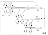
Figure 2 shows an electrical scheme of a portion of the electric machine shown inFigure 1 ; -
Figure 3 is a time diagram of the voltage provided by an inverter branch and the phase current induced by this voltage in one of the semi-windings shown inFigures 1 and2 ; and -
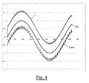
Figure 4 is a graph which shows the result of a numerical simulation relating to operation of the machine according toFigure 1 . -
Figure 1 shows anelectric machine 1 according to an embodiment of the present invention. Theelectric machine 1 preferably comprises anelectric motor 2, aninverter 3 and acontrol unit 4. - The
electric motor 2 preferably is an alternating current motor, more preferably a three-phase electric motor. - In particular, the
electric motor 2 preferably comprises astator 20 and arotor 21. Thestator 20 preferably defines acavity 22 inside which therotor 21 is housed rotatably about an axis of rotation Z. Therotor 21 preferably comprises means (not shown inFigure 1 ) for generating a stationary magnetic field. - The
stator 20 preferably comprises three pairs of semi-windings (namely one pair for each phase) 231a/231b, 232a/232b, 233a/233b arranged in positions angularly spaced at 120° in the circumferential direction. Preferably the two semi-windings of each pair are arranged so as to act as a primary winding and secondary winding of a transformer. For example, the two semi-windings of each pair may be housed inside a same cavity of thestator 20. The semi-windings 231a/231b, 232a/232b, 233a/233b preferably have the same electrical characteristics, in particular have the same inductance. The semi-windings 231a/231b, 232a/232b, 233a/233b are preferably connected together in a star ("Y") configuration, namely have a first end connected to a star centre S, as shown inFigure 2 . According to embodiments not shown in the drawings, the semi-windings 231a/231b, 232a/232b, 233a/233b may be connected together in a triangle ("Δ") configuration. - As shown in
Figure 2 , theinverter 3 preferably comprises a number of parallel inverter branches. In particular, theinverter 3 preferably comprises a same number N≥1 of parallel inverter branches for each semi-winding of theelectric motor 2. By way of a non-limiting example, theinverter 3 shown inFigure 2 comprises N=1inverter branch 31a/31b, 32a/32b, 33a/33b for each semi-winding 231a/231b, 232a/232b, 233a/233b of themotor 3. - With reference to the
inverter branches 31a/31b, each inverter branch preferably comprises a first switch S1a/S1b, a second switch S2a/S2b arranged in series with the first switch S1a/S1b, a first diode D1a/D1b arranged in an anti-parallel configuration with the first switch S1a/S1b and a second diode D2a/D2b arranged in an anti-parallel configuration with the second switch S2a/S2b. Each switch S1a/S1b and S2a/S2b is preferably connected to thecontrol unit 4 and is configured to receive from it a respective control signal suitable for switching the switch between an open state and a closed state, as will be described in greater detail hereinbelow. The other two pairs ofinverter branches 32a/32b, 33a/33b have a structure substantially identical to that of theinverter branches 31a/31b, and therefore a detailed description will not be repeated. Theinverter branches 31a/31b, 32a/32b, 33a/33b are preferably all connected to one or more direct voltage generators which supply a dc supply voltage V across them. - Each semi-winding 231a/231b, 232a/232b, 233a/233b is preferably connected to a
respective inverter branch 31a/31b, 32a/32b, 33a/33b. In particular, with reference for example to the semi-windings 231a/231b, each semi-winding 231a/231b has its end opposite to the star centre S connected to the middle point of thebranch 31a/31b, namely between the first switch S1a/S1b and the second switch S2a/S2b. - Operation of the
electric machine 1 will now be described in detail, with reference in particular to the semi-windings 231a/232b and to theinverter branches 31a/31b which supply them. - In the
inverter branch 31a, when the first switch S1a is in the closed state and the second switch S2a is in the open state, theinverter branch 31a generates across the semi-winding 231a a positive voltage V1a=+V. When instead the first switch S1a is in the open state and the second switch S2a is in the closed state, theinverter branch 31a generates across the semi-winding 231a a negative voltage V1a=-V. When, finally, both the switches S1a, S2a are in the closed state, theinverter branch 31a generates across the semi-winding 231a a voltage V1a=0. The switches S1a and S1b may therefore be switched temporally between the open state and the closed state so as to modulate temporally the voltage V1a. - In particular, preferably, the
control unit 4 sends to the two switches S1a, S2a of theinverter branch 31a control signals so that the voltage V1a has a waveform of a sequence of pulses with pulse frequency fP, the pulse frequency being defined as the inverse of the time which lapses between the leading edges of two consecutive pulses. The pulse frequency fP is chosen so as to be greater than the rotational frequency fR of therotor 21 which is to be obtained. Preferably, the pulse frequency fP is greater than or equal to 10·fR. The pulses may have a positive polarity (namely amplitude +V) or negative polarity (namely amplitude -V). The pulses may moreover have a variable duration or duty cycle, as shown inFigure 3 . - The voltage V1a induces a phase current I1a across the semi-winding 231a. Since the semi-winding 231a is substantially an inductance from an electrical point of view, the phase current I1a which crosses it is proportional to the integral of the voltage Va1 generated by the
inverter branch 31a. The phase current I1a therefore has a waveform which depends on the polarity and the duration or duty cycle of the voltage pulses V1a. Preferably the control signals provided by thecontrol unit 4 to the switches S1a, S2a are chosen so that the phase current I1a has a waveform of a broken line which approximates a sinusoid SIN of frequency fR, as shown inFigure 3 . - The
inverter branch 31b and the semi-winding 231b connected thereto operate in a manner similar to that described above. In other words, thecontrol unit 4 preferably also sends to the switches S1b, S2b control signals able to switch the switches S1b, S2b between a closed state and an open state so as to generate a voltage V1b which induces across the semi-winding 231b a phase current I1b proportional to the integral of the voltage V1b. Preferably the switches S1b, S2b are driven so that the phase current I1b also has a waveform of a broken line which approximates the sinusoid SIN of frequency fR. - However, according to embodiments of the present invention, the switches S1b, S2b of the
inverter branch 31b are driven in phase opposition (namely out of phase by 180°) with respect to the switches S1a, S2a of theinverter branch 31a. In other words, the control signals which thecontrol unit 4 sends to the switches S2a, S2b are identical to the control signals which the control unit sends to the switches S1a, S1b, but are delayed in time relative thereto by 1/2fP. In this way, the voltage V1a generated by theinverter branch 31a and the voltage V1b generated by theinverter branch 31b have waveforms which are identical (namely have the same pulse sequence), but are delayed in time with respect to each other by 1/2fP. Consequently, the phase current I1a and the phase current I1b also have waveforms which are the same (namely the same broken line which approximates the sinusoid SIN of frequency fR), but are delayed in time with respect to each other by 1/2fP. - The sum of the two phase currents I1=I1a+I1b is therefore also a broken line which approximates the sinusoid SIN of frequency fR. However, owing to the reciprocal phase difference of 180° of the two phase currents I1a and I1b based on the times of the pulse frequency fP, the overall phase current I1 approximates the sinusoid SIN in a more accurate manner. In particular, the accuracy of the approximation (namely the amplitude of the higher harmonics) is comparable to that which would be obtained with a single phase winding supplied by a single inverter branch driven with a pulse frequency 2fP.
-
Figure 4 is a graph showing the results of a numerical simulation performed by the inventors. The current Icomp is a comparative phase current which crosses a winding supplied by a single inverter branch driven with pulse frequency fP. The current I1 is instead the phase current obtained as the sum of two phase currents which cross two semi-windings which are connected in a star configuration and supplied by two inverter branches driven with a pulse frequency fP and in phase-opposition. As can be seen from the graph, the ripples of the current I1 with respect to the sinusoid SIN have an amplitude which is substantially halved compared to ripples of the comparative current Icomp and a double frequency 2fP. This means that, for the same power dissipated by the inverter 3 (namely for the same pulse frequency fP), the power dissipated by theelectric motor 2 is advantageously reduced. Similarly, it is possible to obtain the same power dissipated by the motor 2 (namely the same accuracy of approximation of the sinusoid SIN) reducing the pulse frequency fP and therefore the power dissipated by theinverter 3. - Operation of the other pairs of
inverter branches 32a/32b, 33a/33b is preferably similar to that of the pair ofinverter branches 31a/31b. In particular, thecontrol unit 4 preferably sends to the switches of thebranches control unit 4 preferably sends to the switches of thebranches - The control signals provided by the
control unit 4 to the pairs ofbranches 31a/31b, 32a/32b and 33a/33b are moreover reciprocally out of phase by 120° relative to the rotational frequency fR. In this way the three pairs of semi-windings 231a/231b, 232a/232b, 233a/233b provide a three-phase alternating current comprising three overall phase currents I1, I2, I3 which are approximately sinusoidal with frequency fR and reciprocally out of phase by 120°, each of which having ripples with frequency 2 fP relative to the sinusoid SIN. This three-phase alternating current generates a rotating magnetic field with rotational frequency fR which induces a rotation of therotor 21 with respect to the stator 20 (indicated by the arrow A inFigure 1 ). - The electric machine described above offers various advantages.
- First and foremost, as discussed above, for the same power dissipated by the
inverter 3, it is possible to reduce the power dissipated by theelectric motor 2. For the same pulse frequency fP, the phase currents provided by each pair of semi-windings approximate in fact in a more accurate manner an ideal sinusoid compared to the phase current generated by a single winding, since it has ripples with frequency which is doubled and an amplitude which is substantially halved. On the other hand, for the same power dissipated by themotor 2 it is possible to reduce the power dissipated by theinverter 3. It is in fact possible to obtain phase currents which approximate an ideal sinusoid with the same accuracy (namely with ripples having the same frequency and same amplitude) as the phase current generated by a single winding driving the inverter with a pulse frequency fP which is substantially halved. - Moreover, advantageously, the
electric machine 1 may be produced substantially at no additional cost compared to the known machines. In fact, the known electric machines for high-speed applications typically comprise two inverter branches for each phase. This allows the inverter to be driven at particularly high frequencies. However, in the known machines the inverter branches associated with a same phase are driven in-phase with each other. In order to provide an electric machine according to embodiments of the present invention it is sufficient to reconfigure the logic of the control unit which drives the inverter branches so that the inverter branches associated with a same phase are driven in phase opposition to each other and not in-phase. This modification, however, advantageously does not involve substantially any additional cost for the machine. - Moreover, advantageously, the two semi-windings associated with a same phase behave as though they were a transformer. Therefore, when a phase current with non-zero intensity flows in one of the two semi-windings, a current is induced also in the other semi-winding independently of the voltage generated by the inverter branch supplying it. When the switches of this inverter branch are switched so as to induce a phase current with non-zero intensity also in this latter semi-winding, the switching losses are advantageously reduced, because the induced current was already flowing in the semi-winding.
- Although the
inverter 3 of theelectric machine 1 described above comprises a single inverter branch for each semi-winding, this is not limiting. The inverter may in fact comprise a number N≥1 of inverter branches for each semi-winding. Preferably, the number of inverter branches which supply a semi-winding is the same for all the semi-windings. For example, each semi-winding may be supplied by three parallel inverter branches. Inverter branches which supply a same semi-winding are preferably driven in-phase with each other.
Claims (10)
- An electric machine (1) comprising:- an alternating current electric motor (2) comprising a first semi-winding (231a) and a second semi-winding (231b);- an inverter (3) comprising a first inverter branch (31a) electrically connected to said first semi-winding (231a) and a second inverter branch (31b) electrically connected to said second semi-winding (231b);- a control unit (4) suitable for providing a first control signal to said first inverter branch (31a) so as to induce a first alternating current (I1a) in said first semi-winding (231a) and a second control signal to said second inverter branch (32a) so as to induce a second alternating current (I1b) in said second semi-winding (231b), said first alternating current (I1a) and said second alternating current (I1b) having a first frequency (fR), said first control signal and said second control signal having a second frequency (fP) smaller than said first frequency (fR) and being reciprocally out of phase by substantially 180° relative to said second frequency (fP).
- The electric machine (1) according to claim 1, wherein said alternating current electric motor (2) is a three-phase electric motor and wherein a sum of said first alternating current (I1a) and said second alternating current (I1b) is a phase (I1) of a three-phase current.
- The electric machine (1) according to claim 1 or 2, wherein said first semi-winding (231a) and said second semi-winding (231b) are electrically connected according to an "Y" configuration or a "Δ" configuration.
- The electric machine (1) according to any of the preceding claims, wherein said first semi-winding (231a) and said second semi-winding (231b) are arranged so as to behave as a primary winding and a secondary winding of a transformer.
- The electric machine (1) according to any of the preceding claims, wherein said first semi-winding (231a) and said second semi-winding (231b) have electric inductances having a same value.
- The electric machine (1) according to any of the preceding claims, wherein said inverter (3) comprises a number N≥1 of first inverter branches electrically connected to said first semi-winding (231a) and a same number N≥1 of second inverter branches electrically connected to said second semi-winding (231b).
- The electric machine (1) according to any of the preceding claims, wherein each one of said first inverter branch (31a) and second inverter branch (31b) comprises:- a first switch (S1a/S1b);- a second switch (S2a/S2b) connected in series to said first switch (S1a/S1b);- a first diode (D1a/D1b) connected in anti-parallel configuration with said first switch (S1a/S1b); and- a second diode (D2a/D2b) connected in anti-parallel configuration with said second switch (S2a/S2b),wherein said first switch (S1a/S1b) and said second switch (S2a/S2b) are connected to said control unit (4) and are suitable for being switched between an open state and a closed state.
- The electric machine (1) according to any of the preceding claims, wherein said first control signal is suitable for inducing said first inverter branch (31a) to provide a first voltage (V1a) across said first semi-winding (231a) and said second control signal is suitable for inducing said second inverter branch (321b) to provide a second voltage (V1b) across said second semi-winding (231b), said first voltage e(V1a) and said second voltage (V1b) having a same waveform and being reciprocally delayed in time by substantially 1/2fP.
- The electric machine (1) according to claim 8, wherein said waveform comprises a sequence of pulses with pulse frequency equal to said second frequency (fP).
- A method for supplying an alternating current electric motor (2) comprising a first semi-winding (231a) and a second semi-winding (231b) by means of an inverter (3) comprising a first inverter branch (31a) electrically connected to said first semi-winding (231a) and a second inverter branch (31b) electrically connected to said second semi-winding (231b), said method comprising:- providing a first control signal to said first inverter branch (31a) so as to induce a first alternating current (I1a) in said first semi-winding (231a); and- providing a second control signal to said second inverter branch (32a) so as to induce a second alternating current (I1b) in said second semi-winding (231b),wherein said first alternating current (I1a) and said second alternating current (I1b) have a first frequency (fR) and wherein said first control signal and said second control signal have a second frequency (fP) smaller than said first frequency (fR) and are reciprocally out of phase by substantially 180° relative to said second frequency (fP).
Applications Claiming Priority (1)
| Application Number | Priority Date | Filing Date | Title |
|---|---|---|---|
| IT002053A ITMI20122053A1 (en) | 2012-11-30 | 2012-11-30 | ELECTRIC MACHINE INCLUDING AN ALTERNATING CURRENT ELECTRIC MOTOR AND AN INVERTER |
Publications (1)
| Publication Number | Publication Date |
|---|---|
| EP2738935A1 true EP2738935A1 (en) | 2014-06-04 |
Family
ID=47633183
Family Applications (1)
| Application Number | Title | Priority Date | Filing Date |
|---|---|---|---|
| EP20130193243 Ceased EP2738935A1 (en) | 2012-11-30 | 2013-11-18 | Electric machine comprising an alternating current electric motor and an inverter |
Country Status (3)
| Country | Link |
|---|---|
| US (2) | US20140152226A1 (en) |
| EP (1) | EP2738935A1 (en) |
| IT (1) | ITMI20122053A1 (en) |
Families Citing this family (1)
| Publication number | Priority date | Publication date | Assignee | Title |
|---|---|---|---|---|
| KR20230169643A (en) * | 2022-06-09 | 2023-12-18 | 현대자동차주식회사 | Motor driving apparatus |
Citations (4)
| Publication number | Priority date | Publication date | Assignee | Title |
|---|---|---|---|---|
| US20040160201A1 (en) * | 2003-02-14 | 2004-08-19 | Rahman Khwaja M. | Multiple inverter system with low power bus ripples and method therefor |
| US20100072928A1 (en) * | 2008-09-23 | 2010-03-25 | Gm Global Technology Operations, Inc. | Electrical system for pulse-width modulated control of a power inverter using phase-shifted carrier signals and related operating methods |
| US20110074326A1 (en) * | 2009-09-25 | 2011-03-31 | Ut-Battelle, Llc | Electrical motor/generator drive apparatus and method |
| US20110156627A1 (en) * | 2009-12-25 | 2011-06-30 | Denso Corporation | Motor drive and electric power steering apparatus using the same |
Family Cites Families (5)
| Publication number | Priority date | Publication date | Assignee | Title |
|---|---|---|---|---|
| MXPA05001099A (en) * | 2002-07-31 | 2005-09-08 | Smc Electrical Products Inc | Low voltage, two-level, six-pulse induction motor controller driving a medium-to-high voltage, three-or-more-level ac drive inverter bridge. |
| DE102006027716B3 (en) * | 2006-06-15 | 2008-01-24 | Lenze Drive Systems Gmbh | Control with inverters with low switching losses |
| US8183814B2 (en) * | 2008-07-24 | 2012-05-22 | Ewald Franz Fuchs | Alternating current machine with increased torque above and below rated speed for hybrid electric propulsion systems |
| FR2936380B1 (en) * | 2008-09-24 | 2010-10-29 | Messier Bugatti | ELECTRIC ACTUATOR WHICH INCLUDES TWO CURRENT VOLTAGE INVERTERS SUPPLYING AN ELECTRICAL MACHINE AND WHICH IS RECONFIGURABLE IN THE PRESENCE OF A FAULT |
| CN102035446B (en) | 2009-09-29 | 2013-11-06 | 意法半导体研发(上海)有限公司 | System and method for detecting high current condition in electric motor |
-
2012
- 2012-11-30 IT IT002053A patent/ITMI20122053A1/en unknown
-
2013
- 2013-11-18 EP EP20130193243 patent/EP2738935A1/en not_active Ceased
- 2013-11-19 US US14/084,135 patent/US20140152226A1/en not_active Abandoned
-
2016
- 2016-12-01 US US15/366,385 patent/US10320321B2/en active Active
Patent Citations (4)
| Publication number | Priority date | Publication date | Assignee | Title |
|---|---|---|---|---|
| US20040160201A1 (en) * | 2003-02-14 | 2004-08-19 | Rahman Khwaja M. | Multiple inverter system with low power bus ripples and method therefor |
| US20100072928A1 (en) * | 2008-09-23 | 2010-03-25 | Gm Global Technology Operations, Inc. | Electrical system for pulse-width modulated control of a power inverter using phase-shifted carrier signals and related operating methods |
| US20110074326A1 (en) * | 2009-09-25 | 2011-03-31 | Ut-Battelle, Llc | Electrical motor/generator drive apparatus and method |
| US20110156627A1 (en) * | 2009-12-25 | 2011-06-30 | Denso Corporation | Motor drive and electric power steering apparatus using the same |
Also Published As
| Publication number | Publication date |
|---|---|
| US20170085206A1 (en) | 2017-03-23 |
| US20140152226A1 (en) | 2014-06-05 |
| US10320321B2 (en) | 2019-06-11 |
| ITMI20122053A1 (en) | 2014-05-31 |
Similar Documents
| Publication | Publication Date | Title |
|---|---|---|
| CN110089013B (en) | Field winding type rotating electrical machine | |
| US7358698B2 (en) | Field-winding type of synchronous machine | |
| EP2779428B1 (en) | Variable speed constant frequency system with generator and rotating power converter | |
| JP6776841B2 (en) | Rotating electric machine control system and its adjustment method | |
| JP6262336B2 (en) | Modular multiphase motor | |
| AU2005333993A1 (en) | Electric motor | |
| EP3069442B1 (en) | Method and apparatus for control of switched reluctance motors | |
| US20030184245A1 (en) | Drive of rotary electric machine | |
| EP3453109B1 (en) | Switched reluctance machine and power converter | |
| WO2018117144A1 (en) | Field-winding type rotating electric machine | |
| JP2024518405A (en) | Method and apparatus for driving coils of a polyphase electric machine - Patents.com | |
| EP3400646A1 (en) | Software-controlled electronic circuit for switching power to a three-phase motor | |
| KR20170024744A (en) | The high efficiency direct current motor and thereof control method | |
| US7071657B2 (en) | Method and apparatus for the production of power frequency alternating current directly from the output of a single-pole type generator | |
| CN110391706B (en) | Rotating electrical machine | |
| US10320321B2 (en) | Electric machine comprising an alternating current electric motor and an inverter | |
| JP6323220B2 (en) | Synchronous motor drive device | |
| Omar et al. | Performances comparison of various design slot pole of Field Excitation Flux Switching Machines with segmental rotor | |
| KR20230024430A (en) | Direct Drive Systems for Brushless DC (BLDC) Motors | |
| Su et al. | Design of a PM brushless motor drive for hybrid electrical vehicle application | |
| Nadh | A New Five Level Stacked Multilevel Inverter with Reduced Common Mode Voltage | |
| RU2192091C1 (en) | Direct-current drive | |
| WO2019244212A1 (en) | Variable-speed motor device | |
| Nakamura et al. | Phase Control Characteristics of SRMs Driven by Single-Phase Voltage Source Inverter | |
| US20090230907A1 (en) | Method and Circuit Arrangement for Continously Supplying Power to a Brushless Electric Motor |
Legal Events
| Date | Code | Title | Description |
|---|---|---|---|
| PUAI | Public reference made under article 153(3) epc to a published international application that has entered the european phase |
Free format text: ORIGINAL CODE: 0009012 |
|
| 17P | Request for examination filed |
Effective date: 20131118 |
|
| AK | Designated contracting states |
Kind code of ref document: A1 Designated state(s): AL AT BE BG CH CY CZ DE DK EE ES FI FR GB GR HR HU IE IS IT LI LT LU LV MC MK MT NL NO PL PT RO RS SE SI SK SM TR |
|
| AX | Request for extension of the european patent |
Extension state: BA ME |
|
| RAP1 | Party data changed (applicant data changed or rights of an application transferred) |
Owner name: MAVEL S.R.L. Owner name: IFP ENERGIES NOUVELLES |
|
| R17P | Request for examination filed (corrected) |
Effective date: 20150420 |
|
| RBV | Designated contracting states (corrected) |
Designated state(s): AL AT BE BG CH CY CZ DE DK EE ES FI FR GB GR HR HU IE IS IT LI LT LU LV MC MK MT NL NO PL PT RO RS SE SI SK SM TR |
|
| RAP1 | Party data changed (applicant data changed or rights of an application transferred) |
Owner name: MAVEL S.R.L. Owner name: IFP ENERGIES NOUVELLES |
|
| STAA | Information on the status of an ep patent application or granted ep patent |
Free format text: STATUS: EXAMINATION IS IN PROGRESS |
|
| 17Q | First examination report despatched |
Effective date: 20191115 |
|
| R17C | First examination report despatched (corrected) |
Effective date: 20191115 |
|
| RAP1 | Party data changed (applicant data changed or rights of an application transferred) |
Owner name: MAVEL EDT S.P.A. |
|
| STAA | Information on the status of an ep patent application or granted ep patent |
Free format text: STATUS: THE APPLICATION HAS BEEN REFUSED |
|
| 18R | Application refused |
Effective date: 20210501 |