EP2738698A2 - Locking protocol for partitioned and distributed tables - Google Patents
Locking protocol for partitioned and distributed tables Download PDFInfo
- Publication number
- EP2738698A2 EP2738698A2 EP13195150.1A EP13195150A EP2738698A2 EP 2738698 A2 EP2738698 A2 EP 2738698A2 EP 13195150 A EP13195150 A EP 13195150A EP 2738698 A2 EP2738698 A2 EP 2738698A2
- Authority
- EP
- European Patent Office
- Prior art keywords
- node
- lock
- database
- transaction
- acquire
- Prior art date
- Legal status (The legal status is an assumption and is not a legal conclusion. Google has not performed a legal analysis and makes no representation as to the accuracy of the status listed.)
- Granted
Links
Images



Classifications
-
- G—PHYSICS
- G06—COMPUTING OR CALCULATING; COUNTING
- G06F—ELECTRIC DIGITAL DATA PROCESSING
- G06F16/00—Information retrieval; Database structures therefor; File system structures therefor
- G06F16/20—Information retrieval; Database structures therefor; File system structures therefor of structured data, e.g. relational data
- G06F16/21—Design, administration or maintenance of databases
-
- G—PHYSICS
- G06—COMPUTING OR CALCULATING; COUNTING
- G06F—ELECTRIC DIGITAL DATA PROCESSING
- G06F16/00—Information retrieval; Database structures therefor; File system structures therefor
- G06F16/20—Information retrieval; Database structures therefor; File system structures therefor of structured data, e.g. relational data
- G06F16/23—Updating
- G06F16/2308—Concurrency control
-
- G—PHYSICS
- G06—COMPUTING OR CALCULATING; COUNTING
- G06F—ELECTRIC DIGITAL DATA PROCESSING
- G06F16/00—Information retrieval; Database structures therefor; File system structures therefor
- G06F16/20—Information retrieval; Database structures therefor; File system structures therefor of structured data, e.g. relational data
- G06F16/23—Updating
- G06F16/2308—Concurrency control
- G06F16/2336—Pessimistic concurrency control approaches, e.g. locking or multiple versions without time stamps
- G06F16/2343—Locking methods, e.g. distributed locking or locking implementation details
Definitions
- the present embodiments are generally related to a locking protocol for partitioned and distributed database tables.
- Databases of online transaction processing systems have been modified to utilize multi-core parallel processor computer systems efficiently.
- these databases support parallel execution of transactions, are now located in-memory and are organized to be cache efficient.
- the databases support partitioning over a plurality of nodes.
- conventional locking protocols may be improved to mitigate deadlock and overhead.
- the example embodiments include system, method and computer program product embodiments, and combinations and sub-combinations thereof, for providing a locking protocol for partitioned and distributed database tables.
- multi-core parallel processing in-memory partitioned database systems may execute an optimistic intentional exclusive locking protocol.
- a method includes executing, by at least one processor, a first database transaction on a second node, attempting to acquire and acquiring a lock on the second node in intentional exclusive mode.
- the method further includes executing, by the at least one processor, a second database transaction on a first node, acquiring a lock on the first node in exclusive mode and waiting to acquire a lock on the second node in exclusive mode.
- the method includes routing, by the at least one processor, the first database transaction to the first node and unsuccessfully trying to acquire a lock on the first node. The first database transaction is then committed by the at least one processor.
- a method includes attempting, by at least one processor, an intentional exclusive lock for a local database node having a partition of a database table. The method further includes determining, by the at least one processor, that the trying failed and determining whether a remote database node having another partition of the database table has acquired an intentional exclusive lock and acquiring the intentional exclusive lock for the another portion of the database table if not acquired.
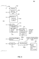
- FIG. 1 illustrates a block diagram of database system hardware architecture according to example embodiments.
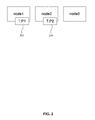
- FIG. 2 illustrates a partitioned database according to example embodiments.
- FIG. 3 illustrates an example instance of deadlock between DDL and DML transactions.
- FIG. 4A illustrates a method based on an optimistic IX locking protocol according to example embodiments.
- FIG. 4B illustrates the optimistic IX locking protocol according to example embodiments.
- FIG. 5 illustrates a further embodiment involving the optimistic IX locking protocol according to example embodiments.
- FIG. 6 illustrates an even further embodiment involving the optimistic IX locking protocol according to example embodiments.
- FIG. 7 illustrates an additional embodiment involving the optimistic IX locking protocol according to example embodiments.
- FIG. 8 illustrates a method of avoiding deadlock using an optimistic IX locking protocol according to example embodiments.
- FIG. 9 illustrates an example computer system according to example embodiments.
- FIG. 1 shows a block diagram of a database system 106 according to example embodiments.
- the database system may be, but is not limited to, an in-memory column-store database system.
- database system 106 may include a computer 108 having at least one processor (CPU) 110.
- CPU 110 in FIG. 1 is shown having one processor, but the database system is not limited to having one processor and may have two or more processors.
- CPU 110 in FIG. 1 is shown as having two cores 112, but the processor 110 may include less than two cores or more than two cores.
- the cores 112 may have a CPU cache 114 that is shared among the cores.
- Each core 112 may have a plurality of hardware contexts, e.g. threads.
- the computer 108 includes random-access memory (RAM) 116 which may include hundreds of GB or TBs of RAM.
- RAM random-access memory
- the database system 106 may be an in-memory column-store database system stored and executed within RAM 116.
- the RAM 116 of an in-memory database system presents a bottleneck for the faster cache 114.
- the RAM 116 and processor 110 may communicate via a bus 118.
- the database system 106 may execute transactions.
- a transaction is a logical unit of work that includes one or more SQL statements.
- a transaction may begin with a first executable statement being DML (data manipulation language) used for inserting, updating, deleting or replacing (upserting) data into partitioned database tables or DDL (data definition language) used for defining partitioned database tables such as creating or dropping a table.
- DML data manipulation language
- DDL data definition language
- a transaction ends with one of the following events: a COMMIT or ROLLBACK statement issues, a DDL statement executes (e.g. automatic commit) or an error occurs (e.g. a lock timeout error or a deadlock error).
- transactions executed are provided full ACID support (atomicity, consistency, isolation and durability).
- the database provides multi-version concurrency control (MVCC) with statement-level and transaction-level isolation as well as multi-level locking and deadlock detection.
- MVCC multi-version concurrency control
- statement-snapshot isolation a statement may see changes that are committed before a statement is started. This is a default isolation level and is also known as read-committed.
- transaction-snapshot isolation a statement may see changes committed before its transaction is started. This is known as repeatable-read or serializable.
- the database system 106 may serialize access to shared resources that may change. Serialization may be provided by locks. A lock may be acquired right before changes are made to a database and released at transaction commit or transaction rollback.
- the DB lock may include a shared mode (S) and an exclusive mode (X).
- the Table Lock may include intentional exclusive (IX) and exclusive (X) modes.
- the record lock may include exclusive (X) mode.
- the example embodiments described below are related to Table Locks, but the embodiments are not limited to Table Locks.
- An exclusive lock may be acquired by a Lock Table command explicitly or by a DDL command implicitly. However, a transaction that holds an exclusive lock is the only transaction that may access the table. Lock requests for the table by other transactions are blocked while the exclusive lock is held.
- Intentional exclusive locks may be acquired by DML implicitly. Multiple transactions may acquire an intentional exclusive lock. Exclusive lock requests for the table by other transactions are blocked while the intentional exclusive lock is held.
- a lock wait timeout may occur.
- a lock wait timeout occurs when a commit/rollback is missing, when an update transaction takes a long time to process or a lock wait timeout configuration value is very small.
- deadlocks may occur and may be automatically detected. Deadlocks may be resolved by rolling back a database transaction that is involved in the deadlock. However, according to example embodiments, deadlocks may be mitigated.
- database tables may be partitioned into multiple partitions as shown in FIG. 2 .
- a database may be divided or partitioned into independent parts and may be distributed.
- each database may be spread amongst a plurality of partitions or nodes and transactions may be performed in parallel on the partitions.
- FIG. 2 shows partition P1 202 and partition P2 204.
- P1 202 is associated with node1
- P2 204 is associated with node2.
- FIG. 3 illustrates deadlock in a partitioned database between DDL and DML transactions.
- an X (exclusive) lock was used to lock a master node and all nodes containing the partitions.
- An X lock may acquire multiple locks on multiple nodes.
- a single database transaction may move around to multiple connections on multiple nodes using statement routing.
- a DML single transaction also acquires an IX lock on multiple nodes, deadlock may occur between DDL and DML operations.
- this conventional method of locking causes deadlock 300 between DDL and DML transactions.
- a first transaction Tx1 302 may be DML and a second transaction Tx2 304 may be DDL.
- Tx1 302 may begin first as DML on node2.
- An IX lock may be applied to node2.
- Tx2 304 may begin DDL.
- An X lock may be applied to node1.
- Tx2 304 attempts to apply an X lock on node2, but is forced to wait for Tx1 302.
- Tx1 302 performs DML on node1 and applies an IX lock on node1 and waits for Tx2 304.
- Tx1 302 has acquired multiple locks on multiple partitions of the same database. Acquisition of IX locks on multiple nodes is avoided according to the embodiments described below.
- each node has its own local lock server and there is not a centralized global lock server. Deadlock problems may be solved according to the example embodiments below.
- deadlock may be avoided between an IX lock used for DML in a first transaction and an X lock used for DDL in a second transaction.
- each node may maintain its own lock manager.
- an optimistic IX locking protocol 400 is shown as pseudocode.
- IX try_lock is performed by a transaction in step 402 before any locking occurs. If try_lock is successful by the transaction, then a local node is locked in an IX mode.
- try_lock fails, then it is determined whether the transaction has already acquired an IX lock on any of the remote nodes in step 404.
- step 406 If the transaction has acquired a lock on one of the remote nodes, then locking of the local node is skipped in step 406.
- the transaction may wait on the local node in step 408 and the transaction may wait to acquire the local node in IX mode without deadlock occurring.
- a first transaction Tx1 410 performs DML and a second transaction Tx2 420 performs DDL.
- DML is performed by Tx1 410 on node2.
- Tx1 410 may perform IX try_lock on node2, which is successful, e.g. Tx1 will acquire the lock in IX mode.
- DDL is performed by Tx2 420.
- An X lock is acquired by Tx2 420 and node1 is locked.
- Tx2 420 will acquire and apply an X lock to node2, but will wait for Tx1 410.
- a database connection is moved from node2 to node1 by Tx1 410.
- Tx1 410 DML is performed by Tx1 410 on node1.
- Tx1 410 will perform IX try_lock on node1, which will fail because Tx2 420 holds an X lock on node1.
- Tx1 410 will then check for an IX lock on a remote node.
- Tx1 410 has an IX lock on node2, and will skip locking.
- Tx1 410 will then commit and Tx2 420 is successful.
- there is no deadlock In other words, DML transactions may only lock a single partition/node of a database at a time, thereby mitigating deadlock.
- a first transaction Tx1 510 performs DML and a second transaction Tx2 520 performs DDL.
- DDL is performed by Tx2 520.
- An X lock is applied to node1 and then an X lock is applied to node2.
- Tx1 510 may perform DML on node2.
- Tx1 510 will perform IX try_lock on node2, but this will fail because Tx2 520 holds an X lock on node2.
- Tx1 510 will check whether there is an IX lock on a remote node.
- Tx1 510 will determine that there are no other IX locks on remote nodes.
- Tx1 510 will then wait for Tx2 520 to complete.
- Tx2 520 will commit and then Tx1 510 may continue.
- the scenario shown in FIG. 5 is successful and no deadlock occurs.
- a first transaction Tx1 610 performs DML and a second transaction Tx2 620 performs DDL.
- DML is performed by Tx1 610 on node2.
- Tx1 610 may perform IX try_lock on node2, which is successful.
- Tx1 610 will lock node2 in IX mode.
- Tx2 620 may add a partition on node3.
- Tx2 620 will apply an X lock to node1, and then attempt to apply an X lock to node2.
- Tx2 620 will have to wait for Tx1 610.
- Tx1 610 will perform statement routing and apply DML to node1.
- Tx1 610 will perform IX try_lock to node1, but this will fail. Tx1 610 will then try to check remote IX locks. Tx1 610 will see that there is an IX lock on node2 and will skip locking node1. Thus, Tx1 610 will then commit. Tx2 620 will be able to commit and deadlocks may be avoided.
- five transactions may occur simultaneously. As shown, DML is performed by Tx1 710, DDL is performed by Tx2 720, DML is performed by Tx3 730, DML is performed by Tx4 740 and DML is performed by Tx5 750.
- Tx1 710 may perform IX try_lock on node2, which is successful. Tx1 710 will lock node2 in IX mode. Next, Tx2 720 performs DDL and applies an X lock to node1 and then applies an X lock to node2. However, Tx2 720 will wait for Tx1 710 to apply the X lock on node2. Next, Tx1 710 may perform IX try_lock on node1. However, this will fail. Tx1 710 will then check whether the transaction has already acquired an IX lock on remote nodes. Tx1 710 will see that it has an IX lock on node2 and will skip locking node1. Thus, Tx1 710 will commit.
- Tx3 730 may perform IX try_lock on node1, and this will fail. However, Tx3 730 does not hold any other IX locks on remote nodes. Thus, Tx3 730 may apply an IX lock on node1, and will wait for Tx2 720.
- Tx4 740 may perform IX try_lock on node2 and this will fail. However, Tx4 740 does not hold any other IX locks on remote nodes. Thus, Tx4 740 may apply an IX lock on node2 and will wait for Tx2 720.
- Tx5 750 may perform IX try_lock on node3. This will succeed and Tx5 750 will obtain an IX lock on node3.
- Tx2 720 may obtain an X lock on node3. However, Tx2 720 will wait for Tx5 750. After Tx5 750 commits, then Tx2 720 will be able to apply the X lock to Tx5 750 and then commit.
- FIG. 8 illustrates a method 800 of avoiding deadlock using an optimistic intentional exclusive locking protocol according to example embodiments.
- a multi-core parallel processing in-memory database system may execute database transactions over multiple partitions and mitigate deadlock.
- a first DML transaction may begin on a second node.
- the first transaction may successfully execute IX try_lock on the second node and acquire an IX lock on the second node.
- a second DDL transaction may begin and the second transaction may acquire an X lock on a first node and acquire an X lock on the second node. However, the second transaction will have to wait for the first transaction to complete on node2.
- step 840 by applying statement routing, the first DML transaction may move from node2 to node1.
- the first transaction may execute IX try_lock on node1. However, IX try_lock will fail because of the X lock held on node1 by the second transaction.
- the first transaction may check if there is an IX lock on a remote node.
- the first transaction may determine that it has an IX lock on the second node, e.g. a remote node.
- the first transaction may skip locking on the first node and commit.
- deadlock does not occur.
- the systems, methods and computer products described herein are implemented using well known computers, such as computer 900 shown in FIG. 9 .
- Computer 900 can be any commercially available and well known computer capable of performing the functions described herein, such as computers available from International Business Machines, Apple, Sun, HP, Dell, Compaq, Digital, Cray, etc.
- Computer 900 includes one or more processors (also called central processing units, or CPUs), such as a processor 906.
- the processor 906 is connected to a communication bus 904.
- Processors 906 may include any conventional or special purpose processor, including, but not limited to, digital signal processor (DSP), field programmable gate array (FPGA), and application specific integrated circuit (ASIC).
- DSP digital signal processor
- FPGA field programmable gate array
- ASIC application specific integrated circuit
- Computer 900 includes one or more graphics processing units (also called GPUs), such as GPU 907.
- GPU 907 is a specialized processor that executes instructions and programs selected for complex graphics and mathematical operations in parallel.
- Computer 900 also includes a main or primary memory 908, such as random access memory (RAM).
- the primary memory 908 has stored therein control logic 928A (computer software), and data.
- Computer 900 also includes one or more secondary storage devices 910.
- the secondary storage devices 910 include, for example, a hard disk drive 912 and/or a removable storage device or drive 914, as well as other types of storage devices, such as memory cards and memory sticks.
- the removable storage drive 914 represents a floppy disk drive, a magnetic tape drive, a compact disk drive, an optical storage device, tape backup, etc.
- the removable storage drive 914 interacts with a removable storage unit 916.
- the removable storage unit 916 includes a computer useable or readable storage medium 924A having stored therein computer software 928B (control logic) and/or data.
- Removable storage unit 916 represents a floppy disk, magnetic tape, compact disk, DVD, optical storage disk, or any other computer data storage device.
- the removable storage drive 914 reads from and/or writes to the removable storage unit 916 in a well-known manner.
- Computer 900 also includes input/output/display devices 922, such as monitors, keyboards, pointing devices, touch-screen displays, etc.
- input/output/display devices 922 such as monitors, keyboards, pointing devices, touch-screen displays, etc.
- Computer 900 further includes a communication or network interface 918.
- the network interface 918 enables the computer 900 to communicate with remote devices.
- the network interface 918 allows computer 900 to communicate over communication networks or mediums 924B (representing a form of a computer useable or readable medium), such as LANs, WANs, the Internet, etc.
- the network interface 918 may interface with remote sites or networks via wired or wireless connections.
- Control logic 928C may be transmitted to and from computer 900 via the communication medium 924B. More particularly, the computer 900 may receive and transmit carrier waves (electromagnetic signals) modulated with control logic 930 via the communication medium 924B.
- Any apparatus or manufacture comprising a computer useable or readable medium having control logic (software) stored therein is referred to herein as a computer program product or program storage device.
- the disclosure can work with software, hardware, and/or operating system implementations other than those described herein. Any software, hardware, and operating system implementations suitable for performing the functions described herein can be used.
Landscapes
- Engineering & Computer Science (AREA)
- Theoretical Computer Science (AREA)
- Databases & Information Systems (AREA)
- Data Mining & Analysis (AREA)
- Physics & Mathematics (AREA)
- General Engineering & Computer Science (AREA)
- General Physics & Mathematics (AREA)
- Information Retrieval, Db Structures And Fs Structures Therefor (AREA)
Abstract
Description
- The present embodiments are generally related to a locking protocol for partitioned and distributed database tables.
- Conventional database management systems have been optimized to perform on hardware with limited main memory, e.g. random access memory (RAM). These conventional database management systems have slower disk input/output (I/O) that serves as a bottleneck.
- However, computer architecture has advanced so that multi-core parallel processing is possible by processor cores communicating using RAM or a shared cache. In addition, RAM is no longer as limited a resource. Databases may now be stored entirely in RAM and thus disk access is no longer a limiting factor for performance. However, multi-core systems present other challenges.
- Databases of online transaction processing systems have been modified to utilize multi-core parallel processor computer systems efficiently. In particular, these databases support parallel execution of transactions, are now located in-memory and are organized to be cache efficient. In addition, the databases support partitioning over a plurality of nodes. Conventionally, there was a single lock manager used for an entire partitioned database table. Maintaining this single lock manager provides challenges such as deadlock and extra network costs as well as overhead resulting from a master database node. However, conventional locking protocols may be improved to mitigate deadlock and overhead.
- Aspects of the invention are set out in the independent claims. Certain preferred features are set out in the dependent claims.
- Briefly stated, the example embodiments include system, method and computer program product embodiments, and combinations and sub-combinations thereof, for providing a locking protocol for partitioned and distributed database tables. According to embodiments, multi-core parallel processing in-memory partitioned database systems may execute an optimistic intentional exclusive locking protocol.
- In an embodiment, a method includes executing, by at least one processor, a first database transaction on a second node, attempting to acquire and acquiring a lock on the second node in intentional exclusive mode. The method further includes executing, by the at least one processor, a second database transaction on a first node, acquiring a lock on the first node in exclusive mode and waiting to acquire a lock on the second node in exclusive mode. In addition, the method includes routing, by the at least one processor, the first database transaction to the first node and unsuccessfully trying to acquire a lock on the first node. The first database transaction is then committed by the at least one processor.
- In a further embodiment, a method includes attempting, by at least one processor, an intentional exclusive lock for a local database node having a partition of a database table. The method further includes determining, by the at least one processor, that the trying failed and determining whether a remote database node having another partition of the database table has acquired an intentional exclusive lock and acquiring the intentional exclusive lock for the another portion of the database table if not acquired.
- Further features and advantages, as well as the structure and operation of various embodiments thereof, are described in detail below with reference to the accompanying drawings. It is noted that the disclosure is not limited to the specific embodiments described herein. Such embodiments are presented herein for illustrative purposes only. Additional embodiments will be apparent to persons skilled in the relevant art(s) based on the teachings contained herein.
- The accompanying drawings, which are incorporated herein and form a part of the specification, illustrate exemplary embodiments and, together with the description, further serve to explain the principles of the disclosure and to enable a person skilled in the relevant art(s) to make and use the contemplated and disclosed embodiments.
-
FIG. 1 illustrates a block diagram of database system hardware architecture according to example embodiments. -
FIG. 2 illustrates a partitioned database according to example embodiments. -
FIG. 3 illustrates an example instance of deadlock between DDL and DML transactions. -
FIG. 4A illustrates a method based on an optimistic IX locking protocol according to example embodiments. -
FIG. 4B illustrates the optimistic IX locking protocol according to example embodiments. -
FIG. 5 illustrates a further embodiment involving the optimistic IX locking protocol according to example embodiments. -
FIG. 6 illustrates an even further embodiment involving the optimistic IX locking protocol according to example embodiments. -
FIG. 7 illustrates an additional embodiment involving the optimistic IX locking protocol according to example embodiments. -
FIG. 8 illustrates a method of avoiding deadlock using an optimistic IX locking protocol according to example embodiments. -
FIG. 9 illustrates an example computer system according to example embodiments. - Features and advantages of embodiments of the present disclosure will become more apparent from the detailed description set forth below when taken in conjunction with the drawings. In the drawings, like reference numbers generally indicate identical, functionally similar, and/or structurally similar elements. Generally, the drawing in which an element first appears is indicated by the leftmost digit(s) in the corresponding reference number.
- The following detailed description refers to the accompanying drawings that illustrate exemplary embodiments consistent with this disclosure. Other embodiments are possible, and modifications can be made to the embodiments within the spirit and scope of the embodiments. Therefore, the detailed description is not meant to limit the embodiments. Rather, the scope of the embodiments is defined by the appended claims.
-
FIG. 1 shows a block diagram of adatabase system 106 according to example embodiments. The database system may be, but is not limited to, an in-memory column-store database system. - In conventional database systems, the focus is directed to optimizing disk access, by minimizing a number of disk pages to be read into main memory when processing a query. This bottleneck is shown in
FIG. 1 at 102. - However, the performance bottleneck in multi-core parallel processor computer systems is found between a CPU cache and RAM. The processor cores wait for data to be loaded from RAM into the processor cache. This bottleneck is shown in
FIG. 1 at 104. This bottleneck is addressed by making efficient usage of the CPU cache. As a number of processor cores increase, CPUs will continue to be able to simultaneously process increasingly more data. - As shown in
FIG. 1 ,database system 106 may include acomputer 108 having at least one processor (CPU) 110. As an example, thedatabase system 106 inFIG. 1 is shown having one processor, but the database system is not limited to having one processor and may have two or more processors. As an example,CPU 110 inFIG. 1 is shown as having twocores 112, but theprocessor 110 may include less than two cores or more than two cores. Thecores 112 may have aCPU cache 114 that is shared among the cores. Eachcore 112 may have a plurality of hardware contexts, e.g. threads. In addition, thecomputer 108 includes random-access memory (RAM) 116 which may include hundreds of GB or TBs of RAM. According to example embodiments, thedatabase system 106 may be an in-memory column-store database system stored and executed withinRAM 116. Thus, as opposed to conventional database systems stored on disk where disk access and speed presents a bottleneck, theRAM 116 of an in-memory database system presents a bottleneck for thefaster cache 114. TheRAM 116 andprocessor 110 may communicate via abus 118. - According to example embodiments, the
database system 106 may execute transactions. A transaction is a logical unit of work that includes one or more SQL statements. A transaction may begin with a first executable statement being DML (data manipulation language) used for inserting, updating, deleting or replacing (upserting) data into partitioned database tables or DDL (data definition language) used for defining partitioned database tables such as creating or dropping a table. In addition, a transaction ends with one of the following events: a COMMIT or ROLLBACK statement issues, a DDL statement executes (e.g. automatic commit) or an error occurs (e.g. a lock timeout error or a deadlock error). - According to example embodiments, transactions executed are provided full ACID support (atomicity, consistency, isolation and durability). In addition, according to example embodiments, the database provides multi-version concurrency control (MVCC) with statement-level and transaction-level isolation as well as multi-level locking and deadlock detection. Regarding statement-snapshot isolation, a statement may see changes that are committed before a statement is started. This is a default isolation level and is also known as read-committed. Regarding transaction-snapshot isolation, a statement may see changes committed before its transaction is started. This is known as repeatable-read or serializable.
- According to example embodiments, the
database system 106 may serialize access to shared resources that may change. Serialization may be provided by locks. A lock may be acquired right before changes are made to a database and released at transaction commit or transaction rollback. According to example embodiments, there are three types of transaction locks: a DB lock, e.g. a meta lock, a Table Lock, e.g. an object lock and a record lock. The DB lock may include a shared mode (S) and an exclusive mode (X). The Table Lock may include intentional exclusive (IX) and exclusive (X) modes. The record lock may include exclusive (X) mode. The example embodiments described below are related to Table Locks, but the embodiments are not limited to Table Locks. - An exclusive lock may be acquired by a Lock Table command explicitly or by a DDL command implicitly. However, a transaction that holds an exclusive lock is the only transaction that may access the table. Lock requests for the table by other transactions are blocked while the exclusive lock is held.
- Intentional exclusive locks may be acquired by DML implicitly. Multiple transactions may acquire an intentional exclusive lock. Exclusive lock requests for the table by other transactions are blocked while the intentional exclusive lock is held.
- According to example embodiments, a lock wait timeout may occur. A lock wait timeout occurs when a commit/rollback is missing, when an update transaction takes a long time to process or a lock wait timeout configuration value is very small. In addition, deadlocks may occur and may be automatically detected. Deadlocks may be resolved by rolling back a database transaction that is involved in the deadlock. However, according to example embodiments, deadlocks may be mitigated.
- According to example embodiments, database tables may be partitioned into multiple partitions as shown in
FIG. 2 . In particular, a database may be divided or partitioned into independent parts and may be distributed. Thus, each database may be spread amongst a plurality of partitions or nodes and transactions may be performed in parallel on the partitions.FIG. 2 showspartition P1 202 andpartition P2 204.P1 202 is associated with node1 andP2 204 is associated with node2. As shown inFIG. 2 , there is not a partition associated with node3, but this is merely an example, and a partition may be associated with node3. - Conventionally, for DML transactions a shared lock is acquired for each partition of a database table. When DDL transactions occur simultaneously, deadlock situations may occur.
-
FIG. 3 illustrates deadlock in a partitioned database between DDL and DML transactions. Conventionally, for DDL an X (exclusive) lock was used to lock a master node and all nodes containing the partitions. An X lock may acquire multiple locks on multiple nodes. - However, according to example embodiments, a single database transaction may move around to multiple connections on multiple nodes using statement routing. Thus, if a DML single transaction also acquires an IX lock on multiple nodes, deadlock may occur between DDL and DML operations.
- In other words, this conventional method of locking
causes deadlock 300 between DDL and DML transactions. As an example, afirst transaction Tx1 302 may be DML and asecond transaction Tx2 304 may be DDL.Tx1 302 may begin first as DML on node2. An IX lock may be applied to node2. Next,Tx2 304 may begin DDL. An X lock may be applied to node1.Tx2 304 attempts to apply an X lock on node2, but is forced to wait forTx1 302. Next,Tx1 302 performs DML on node1 and applies an IX lock on node1 and waits forTx2 304. At this point, there is deadlock becauseTx1 302 has acquired multiple locks on multiple partitions of the same database. Acquisition of IX locks on multiple nodes is avoided according to the embodiments described below. - According to embodiments, each node has its own local lock server and there is not a centralized global lock server. Deadlock problems may be solved according to the example embodiments below.
- According to example embodiments, deadlock may be avoided between an IX lock used for DML in a first transaction and an X lock used for DDL in a second transaction. Rather than a single lock manager, each node may maintain its own lock manager.
- As shown in
FIG. 4A , an optimisticIX locking protocol 400 is shown as pseudocode. First, IX try_lock is performed by a transaction instep 402 before any locking occurs. If try_lock is successful by the transaction, then a local node is locked in an IX mode. - If try_lock fails, then it is determined whether the transaction has already acquired an IX lock on any of the remote nodes in
step 404. - If the transaction has acquired a lock on one of the remote nodes, then locking of the local node is skipped in
step 406. - However, if no other remote lock exists, then the transaction may wait on the local node in
step 408 and the transaction may wait to acquire the local node in IX mode without deadlock occurring. - In a first embodiment shown in
FIG. 4B , afirst transaction Tx1 410 performs DML and asecond transaction Tx2 420 performs DDL. As shown, DML is performed byTx1 410 on node2. Next,Tx1 410 may perform IX try_lock on node2, which is successful, e.g. Tx1 will acquire the lock in IX mode. Simultaneously, DDL is performed byTx2 420. An X lock is acquired byTx2 420 and node1 is locked.Tx2 420 will acquire and apply an X lock to node2, but will wait forTx1 410. A database connection is moved from node2 to node1 byTx1 410. Next, DML is performed byTx1 410 on node1.Tx1 410 will perform IX try_lock on node1, which will fail becauseTx2 420 holds an X lock on node1.Tx1 410 will then check for an IX lock on a remote node.Tx1 410 has an IX lock on node2, and will skip locking.Tx1 410 will then commit andTx2 420 is successful. Thus, there is no deadlock. In other words, DML transactions may only lock a single partition/node of a database at a time, thereby mitigating deadlock. - In an additional embodiment shown in
FIG. 5 , afirst transaction Tx1 510 performs DML and asecond transaction Tx2 520 performs DDL. As shown, DDL is performed byTx2 520. An X lock is applied to node1 and then an X lock is applied to node2. Next,Tx1 510 may perform DML on node2.Tx1 510 will perform IX try_lock on node2, but this will fail becauseTx2 520 holds an X lock on node2. Next,Tx1 510 will check whether there is an IX lock on a remote node.Tx1 510 will determine that there are no other IX locks on remote nodes.Tx1 510 will then wait forTx2 520 to complete.Tx2 520 will commit and thenTx1 510 may continue. Thus, the scenario shown inFIG. 5 is successful and no deadlock occurs. - In a further embodiment shown in
FIG. 6 , afirst transaction Tx1 610 performs DML and asecond transaction Tx2 620 performs DDL. As shown, DML is performed byTx1 610 on node2. Next,Tx1 610 may perform IX try_lock on node2, which is successful.Tx1 610 will lock node2 in IX mode. Simultaneously,Tx2 620 may add a partition on node3. Next,Tx2 620 will apply an X lock to node1, and then attempt to apply an X lock to node2. However,Tx2 620 will have to wait forTx1 610.Tx1 610 will perform statement routing and apply DML to node1.Tx1 610 will perform IX try_lock to node1, but this will fail.Tx1 610 will then try to check remote IX locks.Tx1 610 will see that there is an IX lock on node2 and will skip locking node1. Thus,Tx1 610 will then commit.Tx2 620 will be able to commit and deadlocks may be avoided. - In an even further embodiment shown in
FIG. 7 , five transactions may occur simultaneously. As shown, DML is performed byTx1 710, DDL is performed byTx2 720, DML is performed byTx3 730, DML is performed byTx4 740 and DML is performed byTx5 750. - First,
Tx1 710 may perform IX try_lock on node2, which is successful.Tx1 710 will lock node2 in IX mode. Next,Tx2 720 performs DDL and applies an X lock to node1 and then applies an X lock to node2. However,Tx2 720 will wait forTx1 710 to apply the X lock on node2. Next,Tx1 710 may perform IX try_lock on node1. However, this will fail.Tx1 710 will then check whether the transaction has already acquired an IX lock on remote nodes.Tx1 710 will see that it has an IX lock on node2 and will skip locking node1. Thus,Tx1 710 will commit. - Next,
Tx3 730 may perform IX try_lock on node1, and this will fail. However,Tx3 730 does not hold any other IX locks on remote nodes. Thus,Tx3 730 may apply an IX lock on node1, and will wait forTx2 720. - Next,
Tx4 740 may perform IX try_lock on node2 and this will fail. However,Tx4 740 does not hold any other IX locks on remote nodes. Thus,Tx4 740 may apply an IX lock on node2 and will wait forTx2 720. - Next,
Tx5 750 may perform IX try_lock on node3. This will succeed andTx5 750 will obtain an IX lock on node3. - Next,
Tx2 720 may obtain an X lock on node3. However,Tx2 720 will wait forTx5 750. AfterTx5 750 commits, thenTx2 720 will be able to apply the X lock toTx5 750 and then commit. - Thus, according to example embodiments, there is limited network cost in most cases and there is reduced master node overhead.
- According to embodiments,
FIG. 8 illustrates amethod 800 of avoiding deadlock using an optimistic intentional exclusive locking protocol according to example embodiments. A multi-core parallel processing in-memory database system may execute database transactions over multiple partitions and mitigate deadlock. - As an example, two separate transactions may execute in parallel over database partitions/nodes. In
step 810, a first DML transaction may begin on a second node. - In
step 820, the first transaction may successfully execute IX try_lock on the second node and acquire an IX lock on the second node. - In step 830, a second DDL transaction may begin and the second transaction may acquire an X lock on a first node and acquire an X lock on the second node. However, the second transaction will have to wait for the first transaction to complete on node2.
- In
step 840, by applying statement routing, the first DML transaction may move from node2 to node1. - In
step 850, the first transaction may execute IX try_lock on node1. However, IX try_lock will fail because of the X lock held on node1 by the second transaction. - In
step 860, the first transaction may check if there is an IX lock on a remote node. - In
step 870, the first transaction may determine that it has an IX lock on the second node, e.g. a remote node. - In
step 880, the first transaction may skip locking on the first node and commit. Thus, according to example embodiments, deadlock does not occur. - In an example embodiment, the systems, methods and computer products described herein are implemented using well known computers, such as
computer 900 shown inFIG. 9 . -
Computer 900 can be any commercially available and well known computer capable of performing the functions described herein, such as computers available from International Business Machines, Apple, Sun, HP, Dell, Compaq, Digital, Cray, etc. -
Computer 900 includes one or more processors (also called central processing units, or CPUs), such as aprocessor 906. Theprocessor 906 is connected to acommunication bus 904.Processors 906 may include any conventional or special purpose processor, including, but not limited to, digital signal processor (DSP), field programmable gate array (FPGA), and application specific integrated circuit (ASIC). -
Computer 900 includes one or more graphics processing units (also called GPUs), such asGPU 907.GPU 907 is a specialized processor that executes instructions and programs selected for complex graphics and mathematical operations in parallel. -
Computer 900 also includes a main orprimary memory 908, such as random access memory (RAM). Theprimary memory 908 has stored therein controllogic 928A (computer software), and data. -
Computer 900 also includes one or moresecondary storage devices 910. Thesecondary storage devices 910 include, for example, ahard disk drive 912 and/or a removable storage device or drive 914, as well as other types of storage devices, such as memory cards and memory sticks. Theremovable storage drive 914 represents a floppy disk drive, a magnetic tape drive, a compact disk drive, an optical storage device, tape backup, etc. - The
removable storage drive 914 interacts with aremovable storage unit 916. Theremovable storage unit 916 includes a computer useable orreadable storage medium 924A having stored thereincomputer software 928B (control logic) and/or data.Removable storage unit 916 represents a floppy disk, magnetic tape, compact disk, DVD, optical storage disk, or any other computer data storage device. Theremovable storage drive 914 reads from and/or writes to theremovable storage unit 916 in a well-known manner. -
Computer 900 also includes input/output/display devices 922, such as monitors, keyboards, pointing devices, touch-screen displays, etc. -
Computer 900 further includes a communication ornetwork interface 918. Thenetwork interface 918 enables thecomputer 900 to communicate with remote devices. For example, thenetwork interface 918 allowscomputer 900 to communicate over communication networks ormediums 924B (representing a form of a computer useable or readable medium), such as LANs, WANs, the Internet, etc. Thenetwork interface 918 may interface with remote sites or networks via wired or wireless connections. -
Control logic 928C may be transmitted to and fromcomputer 900 via thecommunication medium 924B. More particularly, thecomputer 900 may receive and transmit carrier waves (electromagnetic signals) modulated withcontrol logic 930 via thecommunication medium 924B. - Any apparatus or manufacture comprising a computer useable or readable medium having control logic (software) stored therein is referred to herein as a computer program product or program storage device. This includes, but is not limited to, the
computer 900, themain memory 908, thesecondary storage devices 910, theremovable storage unit 916 and the carrier waves modulated withcontrol logic 930. Such computer program products, having control logic stored therein that, when executed by one or more data processing devices, cause such data processing devices to operate as described herein, represent embodiments of the disclosure. - The disclosure can work with software, hardware, and/or operating system implementations other than those described herein. Any software, hardware, and operating system implementations suitable for performing the functions described herein can be used.
- It is to be appreciated that the Detailed Description section, and not the Summary and Abstract sections, is intended to be used to interpret the claims. The Summary and Abstract sections may set forth one or more, but not all, exemplary embodiments as contemplated by the inventors, and thus, are not intended to limit the disclosure and the appended claims in any way.
- Embodiments have been described above with the aid of functional building blocks illustrating the implementation of specified functions and relationships thereof. The boundaries of these functional building blocks have been arbitrarily defined herein for the convenience of the description. Alternate boundaries can be defined so long as the specified functions and relationships thereof are appropriately performed.
- The foregoing description of the specific embodiments will so fully reveal the general nature of the disclosure that others can, by applying knowledge within the skill of the art, readily modify and/or adapt for various applications such specific embodiments, without undue experimentation, without departing from the general concept of the disclosure. Therefore, such adaptations and modifications are intended to be within the meaning and range of equivalents of the disclosed embodiments, based on the teaching and guidance presented herein. It is to be understood that the phraseology or terminology herein is for the purpose of description and not of limitation, such that the terminology or phraseology of the specification is to be interpreted by the skilled artisan in light of the teachings and guidance.
- The breadth and scope of the disclosure should not be limited by any of the above-described exemplary embodiments, but should be defined only in accordance with the following claims and their equivalents.
Claims (17)
- A method, comprising:executing, by at least one processor, a first database transaction on a second node, attempting to acquire and acquiring a lock on the second node in intentional exclusive mode;executing, by the at least one processor, a second database transaction on a first node, acquiring a lock on the first node in exclusive mode and waiting to acquire a lock on the second node in exclusive mode;routing, by the at least one processor, the first database transaction to the first node and unsuccessfully trying to acquire a lock on the first node; andcommitting, by the at least one processor, the first database transaction.
- The method of claim 1, wherein the first database transaction is a data manipulation language (DML) transaction.
- The method of claim 1 or 2, wherein the second database transaction is a data definition language (DDL) transaction.
- The method of any of the preceding claims, further comprising:determining that the second node is locked in intentional exclusive mode before committing the first database transaction.
- The method of claim 4, further comprising:skipping locking the first node by the first database transaction.
- The method of any of the preceding claims, further comprising:executing a third database transaction on the first node and unsuccessfully trying to acquire a lock on the first node.
- The method of any of the preceding claims, further comprising:executing a fourth database transaction on the second node and unsuccessfully trying to acquire a lock on the second node.
- A system, comprising:random access memory configured to store a database; andat least one processor configured to:execute a first database transaction on a second node, attempt to acquire and acquire a lock on the second node in intentional exclusive mode;execute a second database transaction on a first node, acquire a lock on the first node in exclusive mode and wait to acquire a lock on the second node in exclusive mode;route the first database transaction to the first node and unsuccessfully try to acquire a lock on the first node; andcommit the first database transaction.
- The system of claim 8, wherein the first database transaction is a data manipulation language (DML) transaction.
- The system of claim 8 or 9, wherein the second database transaction is a data definition language (DDL) transaction.
- The system of any of claims 8 to 10, the at least one processor further configured to:determine that the second node is locked in intentional exclusive mode before committing the first database transaction.
- The system of claim 11, the at least one processor further configured to:skip locking the first node by the first database transaction.
- The system of any of claims 8 to 12, the at least one processor further configured to:execute a third database transaction on the first node and unsuccessfully try to acquire a lock on the first node.
- The system of any of claims 8 to 13, the at least one processor further configured to:execute a fourth database transaction on the second node and unsuccessfully try to acquire a lock on the second node.
- A method, comprising:attempting, by at least one processor, an intentional exclusive lock for a local database node having a partition of a database table; anddetermining, by the at least one processor, that the trying failed and determining whether a remote database node having another partition of the database table has acquired an intentional exclusive lock and acquiring the intentional exclusive lock for the another portion of the database table if not acquired.
- The method of claim 15, further comprising:skipping locking the intentional exclusive lock for the another portion of the database table if acquired.
- A computer-readable medium having instructions stored thereon, execution of which, by at least one computing device, causes the at least one computing device to perform a method as set out in any of claims 1 to 7, 15 or 16.
Applications Claiming Priority (2)
| Application Number | Priority Date | Filing Date | Title |
|---|---|---|---|
| US201261731631P | 2012-11-30 | 2012-11-30 | |
| US13/750,194 US9501502B2 (en) | 2012-11-30 | 2013-01-25 | Locking protocol for partitioned and distributed tables |
Publications (3)
| Publication Number | Publication Date |
|---|---|
| EP2738698A2 true EP2738698A2 (en) | 2014-06-04 |
| EP2738698A3 EP2738698A3 (en) | 2017-01-04 |
| EP2738698B1 EP2738698B1 (en) | 2018-11-14 |
Family
ID=49709541
Family Applications (1)
| Application Number | Title | Priority Date | Filing Date |
|---|---|---|---|
| EP13195150.1A Active EP2738698B1 (en) | 2012-11-30 | 2013-11-29 | Locking protocol for partitioned and distributed tables |
Country Status (2)
| Country | Link |
|---|---|
| US (1) | US9501502B2 (en) |
| EP (1) | EP2738698B1 (en) |
Cited By (1)
| Publication number | Priority date | Publication date | Assignee | Title |
|---|---|---|---|---|
| US20170308547A1 (en) * | 2016-04-25 | 2017-10-26 | Sap Se | Metadata synchronization in a distrubuted database |
Families Citing this family (22)
| Publication number | Priority date | Publication date | Assignee | Title |
|---|---|---|---|---|
| US10698723B2 (en) * | 2014-03-31 | 2020-06-30 | Oracle International Corporation | Dropping an index without blocking locks |
| US10268743B2 (en) | 2015-06-19 | 2019-04-23 | Sap Se | Distributed database transaction protocol |
| US10095764B2 (en) | 2015-06-19 | 2018-10-09 | Sap Se | Multi-replica asynchronous table replication |
| US10795881B2 (en) | 2015-12-18 | 2020-10-06 | Sap Se | Table replication in a database environment |
| US10572510B2 (en) | 2015-12-21 | 2020-02-25 | Sap Se | Distributed database transaction protocol |
| US10235440B2 (en) | 2015-12-21 | 2019-03-19 | Sap Se | Decentralized transaction commit protocol |
| US10552413B2 (en) | 2016-05-09 | 2020-02-04 | Sap Se | Database workload capture and replay |
| US10298702B2 (en) | 2016-07-05 | 2019-05-21 | Sap Se | Parallelized replay of captured database workload |
| US10761946B2 (en) | 2017-02-10 | 2020-09-01 | Sap Se | Transaction commit protocol with recoverable commit identifier |
| US10592528B2 (en) | 2017-02-27 | 2020-03-17 | Sap Se | Workload capture and replay for replicated database systems |
| US10585873B2 (en) | 2017-05-08 | 2020-03-10 | Sap Se | Atomic processing of compound database transactions that modify a metadata entity |
| US11573947B2 (en) | 2017-05-08 | 2023-02-07 | Sap Se | Adaptive query routing in a replicated database environment |
| US10936578B2 (en) | 2017-06-01 | 2021-03-02 | Sap Se | Client-driven commit of distributed write transactions in a database environment |
| US10977227B2 (en) | 2017-06-06 | 2021-04-13 | Sap Se | Dynamic snapshot isolation protocol selection |
| US10698892B2 (en) | 2018-04-10 | 2020-06-30 | Sap Se | Order-independent multi-record hash generation and data filtering |
| US10999392B2 (en) * | 2019-03-01 | 2021-05-04 | Accenture Global Solutions Limited | Message recovery system for computing nodes with replicated databases |
| US11347705B2 (en) | 2019-04-02 | 2022-05-31 | Sap Se | Supporting scalable distributed secondary index using replication engine for high-performance distributed database systems |
| US11709752B2 (en) | 2020-04-02 | 2023-07-25 | Sap Se | Pause and resume in database system workload capture and replay |
| US11615012B2 (en) | 2020-04-03 | 2023-03-28 | Sap Se | Preprocessing in database system workload capture and replay |
| US11650974B2 (en) | 2020-07-01 | 2023-05-16 | Sap Se | Cross-system process control framework |
| CN113205422B (en) * | 2021-05-28 | 2024-12-17 | 中国工商银行股份有限公司 | Transaction deadlock test method and device |
| CN115203226B (en) * | 2022-09-08 | 2023-02-24 | 北京奥星贝斯科技有限公司 | Distributed meter lock operation method, device and equipment |
Family Cites Families (3)
| Publication number | Priority date | Publication date | Assignee | Title |
|---|---|---|---|---|
| US6105026A (en) * | 1997-07-03 | 2000-08-15 | Oracle Corporation | Multi-phase locking for partition maintenance operations |
| US8041691B2 (en) * | 2007-07-30 | 2011-10-18 | Oracle International Corporation | Acquiring locks in wait mode in a deadlock free manner |
| US8924370B2 (en) * | 2011-05-31 | 2014-12-30 | Ori Software Development Ltd. | Efficient distributed lock manager |
-
2013
- 2013-01-25 US US13/750,194 patent/US9501502B2/en active Active
- 2013-11-29 EP EP13195150.1A patent/EP2738698B1/en active Active
Non-Patent Citations (1)
| Title |
|---|
| None |
Cited By (2)
| Publication number | Priority date | Publication date | Assignee | Title |
|---|---|---|---|---|
| US20170308547A1 (en) * | 2016-04-25 | 2017-10-26 | Sap Se | Metadata synchronization in a distrubuted database |
| US10503699B2 (en) * | 2016-04-25 | 2019-12-10 | Sap Se | Metadata synchronization in a distrubuted database |
Also Published As
| Publication number | Publication date |
|---|---|
| EP2738698B1 (en) | 2018-11-14 |
| US9501502B2 (en) | 2016-11-22 |
| EP2738698A3 (en) | 2017-01-04 |
| US20140156619A1 (en) | 2014-06-05 |
Similar Documents
| Publication | Publication Date | Title |
|---|---|---|
| EP2738698B1 (en) | Locking protocol for partitioned and distributed tables | |
| US11263236B2 (en) | Real-time cross-system database replication for hybrid-cloud elastic scaling and high-performance data virtualization | |
| US9965359B2 (en) | Log forwarding to avoid deadlocks during parallel log replay in asynchronous table replication | |
| US8713046B2 (en) | Snapshot isolation support for distributed query processing in a shared disk database cluster | |
| US10191932B2 (en) | Dependency-aware transaction batching for data replication | |
| US10157108B2 (en) | Multi-way, zero-copy, passive transaction log collection in distributed transaction systems | |
| US10268743B2 (en) | Distributed database transaction protocol | |
| US10296371B2 (en) | Passive two-phase commit system for high-performance distributed transaction execution | |
| US9317208B2 (en) | Data row cache for an acid compliant in-memory row store in a page-based RDBMS engine | |
| US9990392B2 (en) | Distributed transaction processing in MPP databases | |
| CN104750720B (en) | The realization that high-performance data is handled under multi-thread concurrent access environment | |
| AU2016244128A1 (en) | Processing database transactions in a distributed computing system | |
| US10706019B2 (en) | Database processing after a lock condition | |
| US9652492B2 (en) | Out-of-order execution of strictly-ordered transactional workloads | |
| US20180074919A1 (en) | Hybrid Database Concurrent Transaction Control | |
| US12032560B2 (en) | Distributed transaction execution management in distributed databases | |
| CN104885054A (en) | System and method for performing a transaction in a massively parallel processing database | |
| CN114661738B (en) | Method, device, equipment and storage medium for adding index | |
| US11940972B2 (en) | Execution of operations on partitioned tables | |
| CN115422188A (en) | Table structure online changing method and device, electronic equipment and storage medium | |
| US12130796B2 (en) | Method and apparatus for distributed database transactions using global timestamping | |
| US9311379B2 (en) | Utilization of data structures to synchronize copies of a resource | |
| US20110191549A1 (en) | Data Array Manipulation | |
| EP3765972A1 (en) | Index management in a multi-process environment | |
| US12373402B1 (en) | Resource efficient schema object creation system |
Legal Events
| Date | Code | Title | Description |
|---|---|---|---|
| PUAI | Public reference made under article 153(3) epc to a published international application that has entered the european phase |
Free format text: ORIGINAL CODE: 0009012 |
|
| 17P | Request for examination filed |
Effective date: 20131129 |
|
| AK | Designated contracting states |
Kind code of ref document: A2 Designated state(s): AL AT BE BG CH CY CZ DE DK EE ES FI FR GB GR HR HU IE IS IT LI LT LU LV MC MK MT NL NO PL PT RO RS SE SI SK SM TR |
|
| AX | Request for extension of the european patent |
Extension state: BA ME |
|
| RAP1 | Party data changed (applicant data changed or rights of an application transferred) |
Owner name: SAP SE |
|
| PUAL | Search report despatched |
Free format text: ORIGINAL CODE: 0009013 |
|
| AK | Designated contracting states |
Kind code of ref document: A3 Designated state(s): AL AT BE BG CH CY CZ DE DK EE ES FI FR GB GR HR HU IE IS IT LI LT LU LV MC MK MT NL NO PL PT RO RS SE SI SK SM TR |
|
| AX | Request for extension of the european patent |
Extension state: BA ME |
|
| RIC1 | Information provided on ipc code assigned before grant |
Ipc: G06F 17/30 20060101AFI20161130BHEP |
|
| R17P | Request for examination filed (corrected) |
Effective date: 20170614 |
|
| RBV | Designated contracting states (corrected) |
Designated state(s): AL AT BE BG CH CY CZ DE DK EE ES FI FR GB GR HR HU IE IS IT LI LT LU LV MC MK MT NL NO PL PT RO RS SE SI SK SM TR |
|
| GRAP | Despatch of communication of intention to grant a patent |
Free format text: ORIGINAL CODE: EPIDOSNIGR1 |
|
| INTG | Intention to grant announced |
Effective date: 20180528 |
|
| GRAS | Grant fee paid |
Free format text: ORIGINAL CODE: EPIDOSNIGR3 |
|
| GRAJ | Information related to disapproval of communication of intention to grant by the applicant or resumption of examination proceedings by the epo deleted |
Free format text: ORIGINAL CODE: EPIDOSDIGR1 |
|
| GRAL | Information related to payment of fee for publishing/printing deleted |
Free format text: ORIGINAL CODE: EPIDOSDIGR3 |
|
| GRAR | Information related to intention to grant a patent recorded |
Free format text: ORIGINAL CODE: EPIDOSNIGR71 |
|
| GRAA | (expected) grant |
Free format text: ORIGINAL CODE: 0009210 |
|
| INTC | Intention to grant announced (deleted) | ||
| AK | Designated contracting states |
Kind code of ref document: B1 Designated state(s): AL AT BE BG CH CY CZ DE DK EE ES FI FR GB GR HR HU IE IS IT LI LT LU LV MC MK MT NL NO PL PT RO RS SE SI SK SM TR |
|
| INTG | Intention to grant announced |
Effective date: 20181005 |
|
| REG | Reference to a national code |
Ref country code: CH Ref legal event code: EP Ref country code: AT Ref legal event code: REF Ref document number: 1065671 Country of ref document: AT Kind code of ref document: T Effective date: 20181115 |
|
| REG | Reference to a national code |
Ref country code: DE Ref legal event code: R079 Ref document number: 602013046595 Country of ref document: DE Free format text: PREVIOUS MAIN CLASS: G06F0017300000 Ipc: G06F0016000000 |
|
| REG | Reference to a national code |
Ref country code: DE Ref legal event code: R096 Ref document number: 602013046595 Country of ref document: DE |
|
| REG | Reference to a national code |
Ref country code: IE Ref legal event code: FG4D |
|
| REG | Reference to a national code |
Ref country code: NL Ref legal event code: MP Effective date: 20181114 |
|
| REG | Reference to a national code |
Ref country code: LT Ref legal event code: MG4D |
|
| REG | Reference to a national code |
Ref country code: AT Ref legal event code: MK05 Ref document number: 1065671 Country of ref document: AT Kind code of ref document: T Effective date: 20181114 |
|
| PG25 | Lapsed in a contracting state [announced via postgrant information from national office to epo] |
Ref country code: NO Free format text: LAPSE BECAUSE OF FAILURE TO SUBMIT A TRANSLATION OF THE DESCRIPTION OR TO PAY THE FEE WITHIN THE PRESCRIBED TIME-LIMIT Effective date: 20190214 Ref country code: LT Free format text: LAPSE BECAUSE OF FAILURE TO SUBMIT A TRANSLATION OF THE DESCRIPTION OR TO PAY THE FEE WITHIN THE PRESCRIBED TIME-LIMIT Effective date: 20181114 Ref country code: AT Free format text: LAPSE BECAUSE OF FAILURE TO SUBMIT A TRANSLATION OF THE DESCRIPTION OR TO PAY THE FEE WITHIN THE PRESCRIBED TIME-LIMIT Effective date: 20181114 Ref country code: BG Free format text: LAPSE BECAUSE OF FAILURE TO SUBMIT A TRANSLATION OF THE DESCRIPTION OR TO PAY THE FEE WITHIN THE PRESCRIBED TIME-LIMIT Effective date: 20190214 Ref country code: HR Free format text: LAPSE BECAUSE OF FAILURE TO SUBMIT A TRANSLATION OF THE DESCRIPTION OR TO PAY THE FEE WITHIN THE PRESCRIBED TIME-LIMIT Effective date: 20181114 Ref country code: LV Free format text: LAPSE BECAUSE OF FAILURE TO SUBMIT A TRANSLATION OF THE DESCRIPTION OR TO PAY THE FEE WITHIN THE PRESCRIBED TIME-LIMIT Effective date: 20181114 Ref country code: FI Free format text: LAPSE BECAUSE OF FAILURE TO SUBMIT A TRANSLATION OF THE DESCRIPTION OR TO PAY THE FEE WITHIN THE PRESCRIBED TIME-LIMIT Effective date: 20181114 Ref country code: ES Free format text: LAPSE BECAUSE OF FAILURE TO SUBMIT A TRANSLATION OF THE DESCRIPTION OR TO PAY THE FEE WITHIN THE PRESCRIBED TIME-LIMIT Effective date: 20181114 Ref country code: IS Free format text: LAPSE BECAUSE OF FAILURE TO SUBMIT A TRANSLATION OF THE DESCRIPTION OR TO PAY THE FEE WITHIN THE PRESCRIBED TIME-LIMIT Effective date: 20190314 |
|
| PG25 | Lapsed in a contracting state [announced via postgrant information from national office to epo] |
Ref country code: GR Free format text: LAPSE BECAUSE OF FAILURE TO SUBMIT A TRANSLATION OF THE DESCRIPTION OR TO PAY THE FEE WITHIN THE PRESCRIBED TIME-LIMIT Effective date: 20190215 Ref country code: NL Free format text: LAPSE BECAUSE OF FAILURE TO SUBMIT A TRANSLATION OF THE DESCRIPTION OR TO PAY THE FEE WITHIN THE PRESCRIBED TIME-LIMIT Effective date: 20181114 Ref country code: PT Free format text: LAPSE BECAUSE OF FAILURE TO SUBMIT A TRANSLATION OF THE DESCRIPTION OR TO PAY THE FEE WITHIN THE PRESCRIBED TIME-LIMIT Effective date: 20190314 Ref country code: RS Free format text: LAPSE BECAUSE OF FAILURE TO SUBMIT A TRANSLATION OF THE DESCRIPTION OR TO PAY THE FEE WITHIN THE PRESCRIBED TIME-LIMIT Effective date: 20181114 Ref country code: SE Free format text: LAPSE BECAUSE OF FAILURE TO SUBMIT A TRANSLATION OF THE DESCRIPTION OR TO PAY THE FEE WITHIN THE PRESCRIBED TIME-LIMIT Effective date: 20181114 Ref country code: AL Free format text: LAPSE BECAUSE OF FAILURE TO SUBMIT A TRANSLATION OF THE DESCRIPTION OR TO PAY THE FEE WITHIN THE PRESCRIBED TIME-LIMIT Effective date: 20181114 |
|
| REG | Reference to a national code |
Ref country code: CH Ref legal event code: PL |
|
| PG25 | Lapsed in a contracting state [announced via postgrant information from national office to epo] |
Ref country code: PL Free format text: LAPSE BECAUSE OF FAILURE TO SUBMIT A TRANSLATION OF THE DESCRIPTION OR TO PAY THE FEE WITHIN THE PRESCRIBED TIME-LIMIT Effective date: 20181114 Ref country code: CZ Free format text: LAPSE BECAUSE OF FAILURE TO SUBMIT A TRANSLATION OF THE DESCRIPTION OR TO PAY THE FEE WITHIN THE PRESCRIBED TIME-LIMIT Effective date: 20181114 Ref country code: LU Free format text: LAPSE BECAUSE OF NON-PAYMENT OF DUE FEES Effective date: 20181129 Ref country code: IT Free format text: LAPSE BECAUSE OF FAILURE TO SUBMIT A TRANSLATION OF THE DESCRIPTION OR TO PAY THE FEE WITHIN THE PRESCRIBED TIME-LIMIT Effective date: 20181114 Ref country code: DK Free format text: LAPSE BECAUSE OF FAILURE TO SUBMIT A TRANSLATION OF THE DESCRIPTION OR TO PAY THE FEE WITHIN THE PRESCRIBED TIME-LIMIT Effective date: 20181114 |
|
| REG | Reference to a national code |
Ref country code: DE Ref legal event code: R097 Ref document number: 602013046595 Country of ref document: DE |
|
| REG | Reference to a national code |
Ref country code: BE Ref legal event code: MM Effective date: 20181130 |
|
| REG | Reference to a national code |
Ref country code: IE Ref legal event code: MM4A |
|
| PG25 | Lapsed in a contracting state [announced via postgrant information from national office to epo] |
Ref country code: MC Free format text: LAPSE BECAUSE OF FAILURE TO SUBMIT A TRANSLATION OF THE DESCRIPTION OR TO PAY THE FEE WITHIN THE PRESCRIBED TIME-LIMIT Effective date: 20181114 Ref country code: LI Free format text: LAPSE BECAUSE OF NON-PAYMENT OF DUE FEES Effective date: 20181130 Ref country code: SK Free format text: LAPSE BECAUSE OF FAILURE TO SUBMIT A TRANSLATION OF THE DESCRIPTION OR TO PAY THE FEE WITHIN THE PRESCRIBED TIME-LIMIT Effective date: 20181114 Ref country code: CH Free format text: LAPSE BECAUSE OF NON-PAYMENT OF DUE FEES Effective date: 20181130 Ref country code: EE Free format text: LAPSE BECAUSE OF FAILURE TO SUBMIT A TRANSLATION OF THE DESCRIPTION OR TO PAY THE FEE WITHIN THE PRESCRIBED TIME-LIMIT Effective date: 20181114 Ref country code: SM Free format text: LAPSE BECAUSE OF FAILURE TO SUBMIT A TRANSLATION OF THE DESCRIPTION OR TO PAY THE FEE WITHIN THE PRESCRIBED TIME-LIMIT Effective date: 20181114 Ref country code: RO Free format text: LAPSE BECAUSE OF FAILURE TO SUBMIT A TRANSLATION OF THE DESCRIPTION OR TO PAY THE FEE WITHIN THE PRESCRIBED TIME-LIMIT Effective date: 20181114 |
|
| PLBE | No opposition filed within time limit |
Free format text: ORIGINAL CODE: 0009261 |
|
| STAA | Information on the status of an ep patent application or granted ep patent |
Free format text: STATUS: NO OPPOSITION FILED WITHIN TIME LIMIT |
|
| 26N | No opposition filed |
Effective date: 20190815 |
|
| PG25 | Lapsed in a contracting state [announced via postgrant information from national office to epo] |
Ref country code: IE Free format text: LAPSE BECAUSE OF NON-PAYMENT OF DUE FEES Effective date: 20181129 Ref country code: SI Free format text: LAPSE BECAUSE OF FAILURE TO SUBMIT A TRANSLATION OF THE DESCRIPTION OR TO PAY THE FEE WITHIN THE PRESCRIBED TIME-LIMIT Effective date: 20181114 |
|
| PG25 | Lapsed in a contracting state [announced via postgrant information from national office to epo] |
Ref country code: BE Free format text: LAPSE BECAUSE OF NON-PAYMENT OF DUE FEES Effective date: 20181130 |
|
| PG25 | Lapsed in a contracting state [announced via postgrant information from national office to epo] |
Ref country code: MT Free format text: LAPSE BECAUSE OF NON-PAYMENT OF DUE FEES Effective date: 20181129 |
|
| PG25 | Lapsed in a contracting state [announced via postgrant information from national office to epo] |
Ref country code: TR Free format text: LAPSE BECAUSE OF FAILURE TO SUBMIT A TRANSLATION OF THE DESCRIPTION OR TO PAY THE FEE WITHIN THE PRESCRIBED TIME-LIMIT Effective date: 20181114 |
|
| PG25 | Lapsed in a contracting state [announced via postgrant information from national office to epo] |
Ref country code: CY Free format text: LAPSE BECAUSE OF FAILURE TO SUBMIT A TRANSLATION OF THE DESCRIPTION OR TO PAY THE FEE WITHIN THE PRESCRIBED TIME-LIMIT Effective date: 20181114 Ref country code: HU Free format text: LAPSE BECAUSE OF FAILURE TO SUBMIT A TRANSLATION OF THE DESCRIPTION OR TO PAY THE FEE WITHIN THE PRESCRIBED TIME-LIMIT; INVALID AB INITIO Effective date: 20131129 Ref country code: MK Free format text: LAPSE BECAUSE OF NON-PAYMENT OF DUE FEES Effective date: 20181114 |
|
| PGFP | Annual fee paid to national office [announced via postgrant information from national office to epo] |
Ref country code: DE Payment date: 20251119 Year of fee payment: 13 |
|
| PGFP | Annual fee paid to national office [announced via postgrant information from national office to epo] |
Ref country code: GB Payment date: 20251121 Year of fee payment: 13 |
|
| PGFP | Annual fee paid to national office [announced via postgrant information from national office to epo] |
Ref country code: FR Payment date: 20251125 Year of fee payment: 13 |