EP2738529B1 - Photoelectric sensor - Google Patents
Photoelectric sensor Download PDFInfo
- Publication number
- EP2738529B1 EP2738529B1 EP13185860.7A EP13185860A EP2738529B1 EP 2738529 B1 EP2738529 B1 EP 2738529B1 EP 13185860 A EP13185860 A EP 13185860A EP 2738529 B1 EP2738529 B1 EP 2738529B1
- Authority
- EP
- European Patent Office
- Prior art keywords
- case
- main body
- positioning
- body part
- connecting hole
- Prior art date
- Legal status (The legal status is an assumption and is not a legal conclusion. Google has not performed a legal analysis and makes no representation as to the accuracy of the status listed.)
- Active
Links
- 238000003780 insertion Methods 0.000 claims description 5
- 230000037431 insertion Effects 0.000 claims description 5
- 239000002184 metal Substances 0.000 claims description 4
- 238000004519 manufacturing process Methods 0.000 description 11
- 238000000034 method Methods 0.000 description 11
- 239000012530 fluid Substances 0.000 description 8
- 238000013461 design Methods 0.000 description 6
- 230000003287 optical effect Effects 0.000 description 6
- 230000005540 biological transmission Effects 0.000 description 3
- 230000007547 defect Effects 0.000 description 2
- 239000000463 material Substances 0.000 description 1
- 238000012544 monitoring process Methods 0.000 description 1
- 238000012545 processing Methods 0.000 description 1
- XLYOFNOQVPJJNP-UHFFFAOYSA-N water Substances O XLYOFNOQVPJJNP-UHFFFAOYSA-N 0.000 description 1
Images

Classifications
-
- G—PHYSICS
- G01—MEASURING; TESTING
- G01J—MEASUREMENT OF INTENSITY, VELOCITY, SPECTRAL CONTENT, POLARISATION, PHASE OR PULSE CHARACTERISTICS OF INFRARED, VISIBLE OR ULTRAVIOLET LIGHT; COLORIMETRY; RADIATION PYROMETRY
- G01J1/00—Photometry, e.g. photographic exposure meter
- G01J1/02—Details
- G01J1/0271—Housings; Attachments or accessories for photometers
-
- G—PHYSICS
- G01—MEASURING; TESTING
- G01D—MEASURING NOT SPECIALLY ADAPTED FOR A SPECIFIC VARIABLE; ARRANGEMENTS FOR MEASURING TWO OR MORE VARIABLES NOT COVERED IN A SINGLE OTHER SUBCLASS; TARIFF METERING APPARATUS; MEASURING OR TESTING NOT OTHERWISE PROVIDED FOR
- G01D11/00—Component parts of measuring arrangements not specially adapted for a specific variable
- G01D11/24—Housings ; Casings for instruments
- G01D11/245—Housings for sensors
-
- G—PHYSICS
- G01—MEASURING; TESTING
- G01J—MEASUREMENT OF INTENSITY, VELOCITY, SPECTRAL CONTENT, POLARISATION, PHASE OR PULSE CHARACTERISTICS OF INFRARED, VISIBLE OR ULTRAVIOLET LIGHT; COLORIMETRY; RADIATION PYROMETRY
- G01J5/00—Radiation pyrometry, e.g. infrared or optical thermometry
- G01J5/02—Constructional details
- G01J5/04—Casings
- G01J5/048—Protective parts
Definitions
- the present invention relates to a photoelectric sensor.
- a photoelectric sensor comprising a case and a main body part set inside the case.
- the case and the main body part are fixedly connected each other by a connecting member (usually a positioning pin or a threaded member and the like) which is simultaneously inserted into a positioning through hole in the case and a corresponding positioning hole in the main body part.
- the connecting member may not be smoothly pressed into the positioning through hole in the case and the corresponding positioning hole in the main body part.
- the connecting member is forcefully pressed thereinto, it is possible to damage the case or the main body part.
- the defects described above often cause that the photoelectric sensor has low production efficiency and higher rejection rate.
- a photoelectric sensor comprises a thin plate-shaped optical body, a circuit block and a casing for incorporating therein the optical body and the circuit block:
- a nearly infrared light incoming through a front surface of the casing is reflected upon a first reflective surface of the optical body. Following this first reflection, a second reflection is made upon a second reflective surface thereof.
- the light having passed through a light collective lens is received by a photoelectric converting element and converted into electric signals for output. Since the optical body comprises a plurality of reflective surfaces, an optical path up to the photoelectric converting element can be incorporated compactly within the thin plate-shaped optical body.
- US 2006/191825 A1 proposes a monitoring port assembly for a fluid treatment system, such as for use in an ultra-violet water treatment system.
- the port assembly comprises a sensor port cup having a port for access to an interior of the fluid treatment vessel.
- the port is offset from the central axis of the sensor port cup.
- a cylindrical body, having an offset through-hole to receive a sensor assembly is disposed within the sensor port cup for rotational movement about the central longitudinal axis between an operational position where the offset through-hole is aligned and coincident with the port, and a servicing position where the offset through-hole is displaced relative to the port. Sensors can be safely and conveniently removed from or installed into a port in the fluid treatment vessel by rotating the cylindrical body from the servicing to the operational position.
- a tip assembly for an IR thermometer apparatus includes a heat sink having a heat sink cavity and a tip section and a fluid path and at least one hydraulic port.
- the tip assembly also includes an IR sensor mechanically seated in the tip section and thermally coupled to the heat sink.
- the tip assembly also includes an electrical connector configured to provide an electrical connection to the tip assembly.
- a fluid having a fluid temperature is introduced into the fluid path via the hydraulic port. The fluid causes the heat sink and the IR sensor to substantially reach one or more pre-determined temperatures by thermal conduction during calibration of the tip assembly.
- Another tip assembly having an internal heat source is described.
- Another tip assembly having an internal heat pump is described.
- a method to calibrate a tip assembly is also described.
- EP 1 878 624 A1 discloses a device for detecting objects near vehicles, particularly for applications in parking aid, anti-break in systems or the like, comprising at least one support associable with the bodywork of a vehicle, at least one sensor associable with the support, suitable for detecting at least one object near the vehicle and associable electronically with at least one processing and control unit by interposition of electronic transmission means, the support comprises connection means to the electronic transmission means in an assembly configuration in which the electronic transmission means are associated electronically and directly with at least a pair of metal terminals of the sensor.
- An object of the present invention is to provide a novel photoelectric sensor, which can overcome the defects described above in the prior art by a simple structure.
- one aspect of the present invention provides a photoelectric sensor, comprising: a case and a main body part set inside the case, wherein the case is cylindrical and the main body part is columnar; and further, the circumferential wall of the case is provided with at least one case connecting hole, the outer surface of the circumferential wall of the main body part is also provided with at least one main body connecting hole, and the case and the main body part are fixedly connected together by at least one connecting member configured to be inserted into the case connecting hole and the main body connecting hole; and the photoelectric sensor further comprising: a positioning protrusion and a positioning recess, one of the positioning protrusion and the positioning recess is provided on the inner surface of the circumferential wall of the case, and the other is provided on the outer surface of the circumferential wall of the main body part, and the positioning recess is suitable for receiving a part or all of the positioning protrusion; when the positioning recess receives a part or all of the positioning protrusion, the position of the case connecting hole is
- the relative rotation between the case and the main body part may be prevented by a simple structure, thereby greatly improving the production efficiency of the photoelectric sensor and reducing the rejection rate in the production process, and accordingly, reducing the labor cost and the production cost.
- a photoelectric sensor comprising: a case and a main body part set inside the case, wherein the case is cylindrical and the main body part is columnar; and further, the circumferential wall of the case is provided with at least one case connecting hole, the outer surface of the circumferential wall of the main body part is also provided with at least one main body connecting hole, and the case and the main body part are fixedly connected together by at least one connecting member configured to be inserted into the case connecting hole and the main body connecting hole; and the photoelectric sensor further comprising: a positioning through hole provided on the circumferential wall of the case and a positioning recess provided on the outer surface of the circumferential wall of the main body part; and when the position of the positioning recess is consistent with that of the positioning through hole, the position of the case connecting hole is consistent with that of the main body connecting hole.
- the positioning recess is a groove.
- the case is a metal case.
- Fig. 1 is a sectional view of the photoelectric sensor according to embodiment 1 of the present invention
- Fig. 2 is a sectional view of the photoelectric sensor according to embodiment 2 of the present invention.
- one aspect of the present invention provides a photoelectric sensor, including a case 1 and a main body part 2 set inside the case.
- the case 1 is cylindrical, and the main body part is columnar.
- the circumferential wall of the case 1 is provided with at least one case connecting hole, and the outer surface of the circumferential wall of the main body part 2 is also provided with at least one main body connecting hole (not shown in figures).
- the case 1 and the main body part 2 are fixedly connected together by at least one connecting member configured to be inserted into the case connecting hole and the main body connecting hole.
- At least one case connecting hole, at least one main body connecting hole and at least one connecting member define a one-to-one correspondence relation.
- the photoelectric sensor further includes a positioning protrusion 41 and a positioning recess 51, one of the positioning protrusion 41 and the positioning recess 51 is provided on the inner surface of the circumferential wall of the case 1, and the other is provided on the outer surface of the circumferential wall of the main body part 2.
- the positioning recess 51 is suitable for receiving a part or all of the positioning protrusion 41, and when the positioning recess 51 receives a part or all of the positioning protrusion 41, the position of the case connecting hole is consistent with that of the main body connecting hole; and in addition, the opening width of an opening, configured to allow the insertion of the positioning protrusion 41, of the positioning protrusion 51 is larger than or equal to the width of the positioning protrusion 41.
- the relative rotation between the case 1 and the main body part 2 is prevented by a simple structure, and when the positioning recess 51 receives a part or all of the positioning protrusion 41, the position of the case connecting hole is consistent with that of the main body connecting hole, thus the connecting member may be easily inserted into the case connecting hole and the main body connecting hole, thereby greatly improving the production efficiency of the photoelectric sensor and reducing the rejection rate in the production process, and accordingly, reducing the labor cost and the production cost.
- the positioning protrusion 41 is provided on the inner surface of the circumferential wall of the case 1, and the positioning recess 51 is provided in a position, corresponding to the positioning protrusion 41, on the outer surface of the circumferential wall of the main body part 2.
- the positioning protrusion 41 is fitted in the positioning recess 51. More specifically, as shown in Fig.
- the positioning protrusion 41 provided on the inner surface of the circumferential wall of the case 1 protrudes from the inner surface of the circumferential wall of the case 1 to the interior of the case 1, and the positioning recess 51 is configured to be suitable for receiving a part or all of the positioning protrusion 41. Further, when the positioning recess 51 receives a part or all of the positioning protrusion 41, the position of the case connecting hole is consistent with that of the main body connecting hole. Further, with the purpose of inserting the positioning protrusion 41 to the positioning recess 51 smoothly, the opening, configured to allow the insertion of the positioning protrusion 41, of the positioning recess 51 is larger than or equal to the width of the positioning protrusion 41.
- the positioning protrusion 41 may be conveniently fitted in the positioning recess 51 both in a process of assembling the case 1 and the main body part 2 and a process of inserting the main body part 2 into the case 1 by a producer, in such a way, the relative rotation between the case 4 and the main body part 5 is effectively prevented by the coordination between the positioning protrusion 41 and the positioning recess 51, and in addition, when the positioning recess 51 receives a part or all of the positioning protrusion 41, the position of the case connecting hole is consistent with that of the main body connecting hole, thus, each connecting member may be inserted into the corresponding case connecting hole and main body connecting hole smoothly.
- the relative rotation between the case 1 and the main body part 2 may also be effectively prevented by a structure defined by the positioning protrusion 41 and the positioning recess 51 in the using process, therefore the positioning stability between the case 1 and the main body part 2 is ensured both in the mounting process and in the using process.
- a structure defined by the positioning protrusion 41 and the positioning recess 51 in the using process therefore the positioning stability between the case 1 and the main body part 2 is ensured both in the mounting process and in the using process.
- the positioning protrusion 41 is configured to be a columnar protrusion provided on the inner surface of the circumferential wall of the front end part of the case 1, and the positioning recess 51 is configured to be a V-shaped groove provided in a corresponding position on the outer surface of the circumferential wall of the main body part 2.
- the positioning protrusion 41 may be fitted in the positioning recess 51 easily, and the positioning protrusion 41 may be positioned at the V-shaped top end of the positioning recess 51, thus the relative rotation between the case 1 and the main body part 2 is prevented by a simple structure.
- the present invention is not limited thereto, those skilled in the art may randomly select the shape of the positioning recess 51 in accordance with actual use and design requirements, for instance, the positioning recess 51 may be a semicircular groove, a rectangular groove or a strip-type groove configured to penetrate through the outer surface of the circumferential wall of the main body part 2 in the longitudinal direction, as long as the positioning recess 51 may accommodate a part or all of the positioning protrusion 41.
- the Fig. 2 of the description below is a sectional view of the photoelectric sensor according to embodiment 2 of the present invention.
- the photoelectric sensor in embodiment 2 is basically similar to the photoelectric sensor in embodiment 1 in terms of structure, and the difference therebetween is that: in embodiment 2, the positioning recess 51 is configured to be a strip-type groove in the inner surface of the circumferential wall of the rear end part of the case 1, and the positioning protrusion 41 is configured to be a strip-type boss provided in a position, corresponding to the positioning recess 51, on the outer surface of the circumferential wall of the main body part 2.
- a producer may fit the positioning protrusion 41 into the positioning recess 51 along the insertion direction (i.e., the extension direction of the strip-type groove and the strip-type protrusion) conveniently in a process of inserting the main body part 2 to the case 1, and in this way, the relative rotation between the case 4 and the main body 5 is effectively prevented by the boss-groove coordination between the positioning protrusion 41 and the positioning recess 51.
- Other components in embodiment 2 are similar to structures in embodiment 1 described above, and will not be repeatedly described herein.
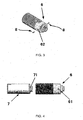
- Fig. 3 of the description below is a sectional view of the photoelectric sensor according to an example.
- Fig. 4 of the description is an exploded schematic view of the photoelectric sensor according this example.
- the photoelectric sensor provided in accordance with this example includes a case 6 and a main body part 7 set inside the case 6; the case 6 is cylindrical, and the main body part 7 is columnar; and in addition, the circumferential wall of the case 6 is provided with at least one case connecting hole 62, and the outer surface of the circumferential wall of the main body part 7 is also provided with at least one main body connecting hole (not shown in the figure), and the case 6 and the main body part 7 are fixedly connected together by at least one connecting member 8 configured to be inserted into the case connecting hole 62 and the main body connecting hole.
- the photoelectric sensor provided in accordance with this example further includes: a positioning through hole 61 provided on the circumferential wall of the case 6, and a positioning recess 71 provided on the outer surface of the circumferential wall of the main body part 7; and when the position of the positioning recess 71 is consistent with that of the positioning through hole 61, the position of the case connecting hole 62 is consistent with that of the main body connecting hole. More specifically, in this example, at least one case connecting hole 62, at least one main body connecting hole and at least one connecting member 8 define a one-to-one correspondence relation.
- case connecting hole of the embodiment 1 may be the same or similar in structure, position and function as the case connecting hole 62 of this example, and the connecting members of the embodiment 1 may be the same or similar in structure, position and function as the connecting members 8 of this example.
- the photoelectric sensor includes: a positioning through hole 61 provided on the circumferential wall of the case 6, and a positioning recess 71 provided in a position, corresponding to the positioning through hole 61, on the outer surface of the circumferential wall of the main body part 7.
- the position of the positioning recess 71 is consistent with that of the positioning through hole 61
- the position of the case connecting hole 62 is consistent with that of the main body connecting hole.
- a producer inserts a positioning member (which may be a positioning pin or other similar members) into the positioning through hole 61 in the circumferential wall of the case 6 at first, and then fits the positioning member configured to be inserted into the positioning through hole 61 into the positioning recess 71 in the outer surface of the circumferential wall of the main body part 7 in a process of setting the main body part 7 into the case 6.
- a positioning member which may be a positioning pin or other similar members
- each connecting member 8 may be inserted into the corresponding case connecting hole 62 and main body connecting hole smoothly.
- the producer may select to pull the positioning member out of the positioning through hole 61 or fixedly mount the positioning member in the positioning through hole 61, which is determined in accordance with actual design and use requirements.
- the positioning member may be a protrusion or a positioning pin and the like provided in a corresponding position of equipment fixture for assembling the case 6 and the main body part 7, and may also be an independent member configured to be manually operated by the producer, which may be determined in accordance with actual design and use requirements for those skilled in the art.
- the case is a metal case.
- the present invention is not limited thereto, and those skilled in the art may optionally select materials of the case and the main body part in accordance with actual use and design requirements.
- an anti-rotating structure only includes a positioning through hole or a positioning protrusion, however, it is obvious for those skilled in the art to optionally select the quantity and setting mode of the positioning through hole or the positioning protrusion in accordance with actual use and design requirements, as long as the anti-rotating structure formed in such a way may prevent the relative rotation between the main body part and the case.
Landscapes
- Physics & Mathematics (AREA)
- General Physics & Mathematics (AREA)
- Spectroscopy & Molecular Physics (AREA)
- Switches Operated By Changes In Physical Conditions (AREA)
Description
- The present invention relates to a photoelectric sensor.
- In the prior art, there is a photoelectric sensor, comprising a case and a main body part set inside the case. Generally speaking, according to this photoelectric sensor, the case and the main body part are fixedly connected each other by a connecting member (usually a positioning pin or a threaded member and the like) which is simultaneously inserted into a positioning through hole in the case and a corresponding positioning hole in the main body part.
- However, as the case is cylindrical usually, and the main body part is columnar correspondingly, when the case and the main body part are assembled, the positioning through hole in the case and the corresponding positioning hole in the main body part may not be aligned usually owing to angle phase difference between the case and the main body part, and thus the connecting member may not be smoothly pressed into the positioning through hole in the case and the corresponding positioning hole in the main body part. Further, if the connecting member is forcefully pressed thereinto, it is possible to damage the case or the main body part. In the actual production process, the defects described above often cause that the photoelectric sensor has low production efficiency and higher rejection rate.
InUS 4 880 974 A , a photoelectric sensor comprises a thin plate-shaped optical body, a circuit block and a casing for incorporating therein the optical body and the circuit block: A nearly infrared light incoming through a front surface of the casing is reflected upon a first reflective surface of the optical body. Following this first reflection, a second reflection is made upon a second reflective surface thereof. The light having passed through a light collective lens is received by a photoelectric converting element and converted into electric signals for output. Since the optical body comprises a plurality of reflective surfaces, an optical path up to the photoelectric converting element can be incorporated compactly within the thin plate-shaped optical body.
US 2006/191825 A1 proposes a monitoring port assembly for a fluid treatment system, such as for use in an ultra-violet water treatment system. The port assembly comprises a sensor port cup having a port for access to an interior of the fluid treatment vessel. The port is offset from the central axis of the sensor port cup. A cylindrical body, having an offset through-hole to receive a sensor assembly, is disposed within the sensor port cup for rotational movement about the central longitudinal axis between an operational position where the offset through-hole is aligned and coincident with the port, and a servicing position where the offset through-hole is displaced relative to the port. Sensors can be safely and conveniently removed from or installed into a port in the fluid treatment vessel by rotating the cylindrical body from the servicing to the operational position.
InUS 2010/265986 A1 , a tip assembly for an IR thermometer apparatus includes a heat sink having a heat sink cavity and a tip section and a fluid path and at least one hydraulic port. The tip assembly also includes an IR sensor mechanically seated in the tip section and thermally coupled to the heat sink. The tip assembly also includes an electrical connector configured to provide an electrical connection to the tip assembly. A fluid having a fluid temperature is introduced into the fluid path via the hydraulic port. The fluid causes the heat sink and the IR sensor to substantially reach one or more pre-determined temperatures by thermal conduction during calibration of the tip assembly. Another tip assembly having an internal heat source is described. Another tip assembly having an internal heat pump is described. A method to calibrate a tip assembly is also described.
EP 1 878 624 A1 - An object of the present invention is to provide a novel photoelectric sensor, which can overcome the defects described above in the prior art by a simple structure.
- To be specific, one aspect of the present invention provides a photoelectric sensor, comprising: a case and a main body part set inside the case, wherein the case is cylindrical and the main body part is columnar; and further, the circumferential wall of the case is provided with at least one case connecting hole, the outer surface of the circumferential wall of the main body part is also provided with at least one main body connecting hole, and the case and the main body part are fixedly connected together by at least one connecting member configured to be inserted into the case connecting hole and the main body connecting hole; and the photoelectric sensor further comprising: a positioning protrusion and a positioning recess, one of the positioning protrusion and the positioning recess is provided on the inner surface of the circumferential wall of the case, and the other is provided on the outer surface of the circumferential wall of the main body part, and the positioning recess is suitable for receiving a part or all of the positioning protrusion; when the positioning recess receives a part or all of the positioning protrusion, the position of the case connecting hole is consistent with that of the main body connecting hole, and the opening width of an opening, configured to allow the insertion of the positioning protrusion, of the positioning recess is larger than or equal to the width of the positioning protrusion; and when the main body part is set inside the case, a part or all of the positioning protrusion is positioned in the positioning recess.
- With such a structure, the relative rotation between the case and the main body part may be prevented by a simple structure, thereby greatly improving the production efficiency of the photoelectric sensor and reducing the rejection rate in the production process, and accordingly, reducing the labor cost and the production cost.
- Another example provides a photoelectric sensor, comprising: a case and a main body part set inside the case, wherein the case is cylindrical and the main body part is columnar; and further, the circumferential wall of the case is provided with at least one case connecting hole, the outer surface of the circumferential wall of the main body part is also provided with at least one main body connecting hole, and the case and the main body part are fixedly connected together by at least one connecting member configured to be inserted into the case connecting hole and the main body connecting hole; and the photoelectric sensor further comprising: a positioning through hole provided on the circumferential wall of the case and a positioning recess provided on the outer surface of the circumferential wall of the main body part; and when the position of the positioning recess is consistent with that of the positioning through hole, the position of the case connecting hole is consistent with that of the main body connecting hole.
- Preferably, in accordance with the photoelectric sensor provided by the present invention, the positioning recess is a groove.
- Preferably, in accordance with the photoelectric sensor provided by the present invention, the case is a metal case.
-
-
Fig. 1 is a sectional view of the photoelectric sensor according toembodiment 1 of the present invention; -
Fig. 2 is a sectional view of the photoelectric sensor according toembodiment 2 of the present invention; -
Fig. 3 is a sectional view of the photoelectric sensor according to an example and -
Fig. 4 is an exploded schematic view of the photoelectric sensor according to an example. - Preferred embodiments of the present invention are described below in combination with figures.
-
Fig. 1 is a sectional view of the photoelectric sensor according toembodiment 1 of the present invention; andFig. 2 is a sectional view of the photoelectric sensor according toembodiment 2 of the present invention. - To be specific, as described in
Figs. 1 and 2 of the description below, one aspect of the present invention provides a photoelectric sensor, including acase 1 and amain body part 2 set inside the case. Further, thecase 1 is cylindrical, and the main body part is columnar. Further, the circumferential wall of thecase 1 is provided with at least one case connecting hole, and the outer surface of the circumferential wall of themain body part 2 is also provided with at least one main body connecting hole (not shown in figures). Thecase 1 and themain body part 2 are fixedly connected together by at least one connecting member configured to be inserted into the case connecting hole and the main body connecting hole. More specifically, according to the present invention, at least one case connecting hole, at least one main body connecting hole and at least one connecting member define a one-to-one correspondence relation. The photoelectric sensor further includes apositioning protrusion 41 and a positioning recess 51, one of thepositioning protrusion 41 and thepositioning recess 51 is provided on the inner surface of the circumferential wall of thecase 1, and the other is provided on the outer surface of the circumferential wall of themain body part 2. Further, thepositioning recess 51 is suitable for receiving a part or all of thepositioning protrusion 41, and when thepositioning recess 51 receives a part or all of thepositioning protrusion 41, the position of the case connecting hole is consistent with that of the main body connecting hole; and in addition, the opening width of an opening, configured to allow the insertion of thepositioning protrusion 41, of thepositioning protrusion 51 is larger than or equal to the width of thepositioning protrusion 41. When themain body part 2 is set inside thecase 1, a part or all of thepositioning protrusion 41 is positioned in the positioning recess 51. - With of such structure, the relative rotation between the
case 1 and themain body part 2 is prevented by a simple structure, and when thepositioning recess 51 receives a part or all of thepositioning protrusion 41, the position of the case connecting hole is consistent with that of the main body connecting hole, thus the connecting member may be easily inserted into the case connecting hole and the main body connecting hole, thereby greatly improving the production efficiency of the photoelectric sensor and reducing the rejection rate in the production process, and accordingly, reducing the labor cost and the production cost. - More specifically, as shown in
Fig. 1 of the description, in accordance withembodiment 1 of the present invention, thepositioning protrusion 41 is provided on the inner surface of the circumferential wall of thecase 1, and thepositioning recess 51 is provided in a position, corresponding to thepositioning protrusion 41, on the outer surface of the circumferential wall of themain body part 2. When themain body part 2 is set inside thecase 1, thepositioning protrusion 41 is fitted in thepositioning recess 51. More specifically, as shown inFig. 1 of the description, thepositioning protrusion 41 provided on the inner surface of the circumferential wall of thecase 1 protrudes from the inner surface of the circumferential wall of thecase 1 to the interior of thecase 1, and thepositioning recess 51 is configured to be suitable for receiving a part or all of thepositioning protrusion 41. Further, when the positioning recess 51 receives a part or all of thepositioning protrusion 41, the position of the case connecting hole is consistent with that of the main body connecting hole. Further, with the purpose of inserting thepositioning protrusion 41 to the positioning recess 51 smoothly, the opening, configured to allow the insertion of thepositioning protrusion 41, of thepositioning recess 51 is larger than or equal to the width of thepositioning protrusion 41. Thus, thepositioning protrusion 41 may be conveniently fitted in the positioning recess 51 both in a process of assembling thecase 1 and themain body part 2 and a process of inserting themain body part 2 into thecase 1 by a producer, in such a way, the relative rotation between the case 4 and the main body part 5 is effectively prevented by the coordination between thepositioning protrusion 41 and the positioning recess 51, and in addition, when thepositioning recess 51 receives a part or all of thepositioning protrusion 41, the position of the case connecting hole is consistent with that of the main body connecting hole, thus, each connecting member may be inserted into the corresponding case connecting hole and main body connecting hole smoothly. Further, in accordance with the photoelectric sensor provided byembodiment 1, the relative rotation between thecase 1 and themain body part 2 may also be effectively prevented by a structure defined by thepositioning protrusion 41 and the positioning recess 51 in the using process, therefore the positioning stability between thecase 1 and themain body part 2 is ensured both in the mounting process and in the using process. With such a structure, not only is the production efficiency of the photoelectric sensor greatly improved and the rejection rate in the production process is reduced, so that the labor cost and the production cost are reduced, but also damage of the photoelectric sensor caused by the relative rotation between thecase 1 and themain body part 2 in the using process may also be avoided. - More specifically, as shown in
Fig. 1 of the description below, according toembodiment 1 of the present invention, thepositioning protrusion 41 is configured to be a columnar protrusion provided on the inner surface of the circumferential wall of the front end part of thecase 1, and thepositioning recess 51 is configured to be a V-shaped groove provided in a corresponding position on the outer surface of the circumferential wall of themain body part 2. With such a structure, thepositioning protrusion 41 may be fitted in the positioning recess 51 easily, and thepositioning protrusion 41 may be positioned at the V-shaped top end of the positioning recess 51, thus the relative rotation between thecase 1 and themain body part 2 is prevented by a simple structure. However, it is evident that the present invention is not limited thereto, those skilled in the art may randomly select the shape of the positioning recess 51 in accordance with actual use and design requirements, for instance, thepositioning recess 51 may be a semicircular groove, a rectangular groove or a strip-type groove configured to penetrate through the outer surface of the circumferential wall of themain body part 2 in the longitudinal direction, as long as the positioning recess 51 may accommodate a part or all of thepositioning protrusion 41. - The preferred embodiments of the present invention have been described above, and those skilled in the art may make various variations in accordance with the preferred embodiments described above without departing from the scope of the present invention. A variant of the present invention is further illustrated with reference to
Fig. 2 of the description as follows. - The
Fig. 2 of the description below is a sectional view of the photoelectric sensor according toembodiment 2 of the present invention. The photoelectric sensor inembodiment 2 is basically similar to the photoelectric sensor inembodiment 1 in terms of structure, and the difference therebetween is that: inembodiment 2, thepositioning recess 51 is configured to be a strip-type groove in the inner surface of the circumferential wall of the rear end part of thecase 1, and thepositioning protrusion 41 is configured to be a strip-type boss provided in a position, corresponding to the positioning recess 51, on the outer surface of the circumferential wall of themain body part 2. By employing such a structure, in the process of assembling thecase 1 and themain body part 2, a producer may fit thepositioning protrusion 41 into thepositioning recess 51 along the insertion direction (i.e., the extension direction of the strip-type groove and the strip-type protrusion) conveniently in a process of inserting themain body part 2 to thecase 1, and in this way, the relative rotation between the case 4 and the main body 5 is effectively prevented by the boss-groove coordination between the positioningprotrusion 41 and thepositioning recess 51. Other components inembodiment 2 are similar to structures inembodiment 1 described above, and will not be repeatedly described herein. -
Fig. 3 of the description below is a sectional view of the photoelectric sensor according to an example.Fig. 4 of the description is an exploded schematic view of the photoelectric sensor according this example. The photoelectric sensor provided in accordance with this example includes acase 6 and amain body part 7 set inside thecase 6; thecase 6 is cylindrical, and themain body part 7 is columnar; and in addition, the circumferential wall of thecase 6 is provided with at least onecase connecting hole 62, and the outer surface of the circumferential wall of themain body part 7 is also provided with at least one main body connecting hole (not shown in the figure), and thecase 6 and themain body part 7 are fixedly connected together by at least one connectingmember 8 configured to be inserted into thecase connecting hole 62 and the main body connecting hole. Further, the photoelectric sensor provided in accordance with this example further includes: a positioning throughhole 61 provided on the circumferential wall of thecase 6, and apositioning recess 71 provided on the outer surface of the circumferential wall of themain body part 7; and when the position of thepositioning recess 71 is consistent with that of the positioning throughhole 61, the position of thecase connecting hole 62 is consistent with that of the main body connecting hole. More specifically, in this example, at least onecase connecting hole 62, at least one main body connecting hole and at least one connectingmember 8 define a one-to-one correspondence relation. It should be noted that the case connecting hole of theembodiment 1 may be the same or similar in structure, position and function as thecase connecting hole 62 of this example, and the connecting members of theembodiment 1 may be the same or similar in structure, position and function as the connectingmembers 8 of this example. - More specifically, as shown in
Figs. 3 and 4 of the description below, in this example, the photoelectric sensor includes: a positioning throughhole 61 provided on the circumferential wall of thecase 6, and apositioning recess 71 provided in a position, corresponding to the positioning throughhole 61, on the outer surface of the circumferential wall of themain body part 7. When the position of thepositioning recess 71 is consistent with that of the positioning throughhole 61, the position of thecase connecting hole 62 is consistent with that of the main body connecting hole. More specifically, in this example, in a process of assembling thecase 6 and themain body part 7, a producer inserts a positioning member (which may be a positioning pin or other similar members) into the positioning throughhole 61 in the circumferential wall of thecase 6 at first, and then fits the positioning member configured to be inserted into the positioning throughhole 61 into thepositioning recess 71 in the outer surface of the circumferential wall of themain body part 7 in a process of setting themain body part 7 into thecase 6. Under such circumstance, the position of thecase connecting hole 62 is consistent with that of the main body connecting hole. In this way, the relative rotation between thecase 6 and themain body part 7 is prevented by the positioning member, and thus each connectingmember 8 may be inserted into the correspondingcase connecting hole 62 and main body connecting hole smoothly. After thecase 6 and themain body part 7 are fixedly connected together through the connectingmember 8, the producer may select to pull the positioning member out of the positioning throughhole 61 or fixedly mount the positioning member in the positioning throughhole 61, which is determined in accordance with actual design and use requirements. More specifically, in this example, the positioning member may be a protrusion or a positioning pin and the like provided in a corresponding position of equipment fixture for assembling thecase 6 and themain body part 7, and may also be an independent member configured to be manually operated by the producer, which may be determined in accordance with actual design and use requirements for those skilled in the art. - Further, in the embodiments and the example described above, the case is a metal case. However, the present invention is not limited thereto, and those skilled in the art may optionally select materials of the case and the main body part in accordance with actual use and design requirements.
- Furthermore, except for concrete structures in two embodiments described above, those skilled in the art may make various variants in accordance with a basic design concept of the present invention, without going beyond the scope claimed by claims below of the present invention. For instance, in the embodiments described above, an anti-rotating structure only includes a positioning through hole or a positioning protrusion, however, it is obvious for those skilled in the art to optionally select the quantity and setting mode of the positioning through hole or the positioning protrusion in accordance with actual use and design requirements, as long as the anti-rotating structure formed in such a way may prevent the relative rotation between the main body part and the case.
Claims (3)
- A photoelectric sensor, comprising: a case (1, 6); and
a main body part (2, 7) set inside the case (1, 6), wherein
the case (1, 6) is cylindrical and the main body part (2, 7) is columnar; and further, the circumferential wall of the case (1, 6) is provided with at least one case connecting hole (62), the outer surface of the circumferential wall of the main body part (2, 7) is also provided with at least one main body connecting hole, and the case (1, 6) and the main body part (2, 7) are fixedly connected together by at least one connecting member (8) configured to be inserted into the case connecting hole (62) and the main body connecting hole; and
the photoelectric sensor further comprises: a positioning protrusion (41) and a positioning recess (51, 71), one of the positioning protrusion (41) and the positioning recess (51, 71) is provided on the inner surface of the circumferential wall of the case (1, 6), the other is provided on the outer surface of the circumferential wall of the main body part (2, 7), and the positioning recess (51, 71) is suitable for receiving a part or all of the positioning protrusion (41); and
when the positioning recess (51, 71) receives a part or all of the positioning protrusion (41), the position of the case connecting hole (62) is consistent with that of the main body connecting hole;
the opening width of an opening, configured to allow the insertion of the positioning protrusion (41), of the positioning recess (51, 71) is larger than or equal to the width of the positioning protrusion (41); and
when the main body part (2, 7) is set inside the case (1, 6), a part or all of the positioning protrusion (41) is positioned in the positioning recess (51, 71). - The photoelectric sensor according to Claim 1, wherein the positioning recess (51, 71) is a V shape groove.
- The photoelectric sensor according to Claim 1 or 2, wherein, the case (1, 6) is a metal case.
Applications Claiming Priority (1)
| Application Number | Priority Date | Filing Date | Title |
|---|---|---|---|
| CN 201220652585 CN203177876U (en) | 2012-11-30 | 2012-11-30 | Photoelectric sensor |
Publications (2)
| Publication Number | Publication Date |
|---|---|
| EP2738529A1 EP2738529A1 (en) | 2014-06-04 |
| EP2738529B1 true EP2738529B1 (en) | 2015-11-04 |
Family
ID=49074559
Family Applications (1)
| Application Number | Title | Priority Date | Filing Date |
|---|---|---|---|
| EP13185860.7A Active EP2738529B1 (en) | 2012-11-30 | 2013-09-25 | Photoelectric sensor |
Country Status (3)
| Country | Link |
|---|---|
| EP (1) | EP2738529B1 (en) |
| CN (1) | CN203177876U (en) |
| DE (1) | DE202013012243U1 (en) |
Families Citing this family (1)
| Publication number | Priority date | Publication date | Assignee | Title |
|---|---|---|---|---|
| FR3024611B1 (en) | 2014-08-01 | 2016-09-02 | Alstom Transp Tech | ELECTRIC MOTOR AND DISASSEMBLY METHOD |
Family Cites Families (4)
| Publication number | Priority date | Publication date | Assignee | Title |
|---|---|---|---|---|
| US4880974A (en) * | 1988-10-14 | 1989-11-14 | Wako Corporation | Photoelectric sensor employing custom lens member |
| US7575671B2 (en) * | 2005-02-25 | 2009-08-18 | R-Can Environmental Inc. | Monitoring port assembly for fluid treatment systems |
| ITMO20060225A1 (en) * | 2006-07-11 | 2008-01-12 | Meta System Spa | DEVICE FOR DETECTING OBJECTS NEAR VEHICLES, PARTICULARLY FOR APPLICATIONS IN PARKING, ANTI-INTRUSION OR SIMILAR ASSISTANCE SYSTEMS. |
| US8186876B2 (en) * | 2009-04-20 | 2012-05-29 | Welch Allyn, Inc. | Calibrated assembly for IR thermometer apparatus |
-
2012
- 2012-11-30 CN CN 201220652585 patent/CN203177876U/en not_active Expired - Lifetime
-
2013
- 2013-09-25 EP EP13185860.7A patent/EP2738529B1/en active Active
- 2013-09-25 DE DE202013012243.9U patent/DE202013012243U1/en not_active Expired - Lifetime
Also Published As
| Publication number | Publication date |
|---|---|
| DE202013012243U1 (en) | 2015-10-19 |
| EP2738529A1 (en) | 2014-06-04 |
| CN203177876U (en) | 2013-09-04 |
Similar Documents
| Publication | Publication Date | Title |
|---|---|---|
| US11221543B2 (en) | Camera module | |
| EP2950613B1 (en) | Induction coil assembly and induction hob comprising an induction coil assembly | |
| JP6378638B2 (en) | Sensor configuration | |
| US6389903B1 (en) | Pressure-detecting device coupling member with interchangeable connector part | |
| KR102198051B1 (en) | Compressor | |
| KR102280348B1 (en) | Camera module | |
| US11121607B2 (en) | Electronics housing for an E-axis drive and E-axis having an electronics housing | |
| KR20160104316A (en) | Camera module and camera for vehicle | |
| TWI834765B (en) | Sensor assembly and physical quantity measuring device | |
| US20140213103A1 (en) | Adapter device with mechanical interface | |
| CN105628293B (en) | Pressure sensor | |
| CN112782808A (en) | Optical fiber device, method for producing an optical fiber device, and aircraft | |
| CN114424030B (en) | Low heat resistance sensor | |
| US20110260034A1 (en) | Photo detection device | |
| US9247115B2 (en) | Imager module for a camera, camera and method for manufacturing the imager module | |
| CN111561554A (en) | Adapter plate | |
| EP2705986A1 (en) | Retaining device for retaining a sensor device on a pane of a motor vehicle | |
| US7546766B2 (en) | Sun sensor using MID technology | |
| US20180003582A1 (en) | Device for sensing a pressure of a fluid medium | |
| EP3404384B1 (en) | Temperature detection device | |
| KR102167663B1 (en) | Camera module | |
| EP1878624B1 (en) | Device for detecting objects near vehicles | |
| CN114199391A (en) | Sensor assembly | |
| CN111795755B (en) | Sensor devices, methods and vehicles for manufacturing sensor devices | |
| EP3958414B1 (en) | Panel comprising temperature abnormality detection device |
Legal Events
| Date | Code | Title | Description |
|---|---|---|---|
| REG | Reference to a national code |
Ref country code: DE Ref legal event code: R138 Ref document number: 602013003739 Country of ref document: DE Free format text: GERMAN DOCUMENT NUMBER IS 602013003739 Ref country code: DE Ref legal event code: R138 Ref document number: 202013012243 Country of ref document: DE Free format text: GERMAN DOCUMENT NUMBER IS 602013003739 |
|
| PUAI | Public reference made under article 153(3) epc to a published international application that has entered the european phase |
Free format text: ORIGINAL CODE: 0009012 |
|
| 17P | Request for examination filed |
Effective date: 20130925 |
|
| AK | Designated contracting states |
Kind code of ref document: A1 Designated state(s): AL AT BE BG CH CY CZ DE DK EE ES FI FR GB GR HR HU IE IS IT LI LT LU LV MC MK MT NL NO PL PT RO RS SE SI SK SM TR |
|
| AX | Request for extension of the european patent |
Extension state: BA ME |
|
| GRAJ | Information related to disapproval of communication of intention to grant by the applicant or resumption of examination proceedings by the epo deleted |
Free format text: ORIGINAL CODE: EPIDOSDIGR1 |
|
| GRAP | Despatch of communication of intention to grant a patent |
Free format text: ORIGINAL CODE: EPIDOSNIGR1 |
|
| RIN1 | Information on inventor provided before grant (corrected) |
Inventor name: IIDA, HIROYUKI Inventor name: YE, JIONG |
|
| INTG | Intention to grant announced |
Effective date: 20150518 |
|
| GRAS | Grant fee paid |
Free format text: ORIGINAL CODE: EPIDOSNIGR3 |
|
| GRAA | (expected) grant |
Free format text: ORIGINAL CODE: 0009210 |
|
| AK | Designated contracting states |
Kind code of ref document: B1 Designated state(s): AL AT BE BG CH CY CZ DE DK EE ES FI FR GB GR HR HU IE IS IT LI LT LU LV MC MK MT NL NO PL PT RO RS SE SI SK SM TR |
|
| REG | Reference to a national code |
Ref country code: GB Ref legal event code: FG4D |
|
| REG | Reference to a national code |
Ref country code: CH Ref legal event code: EP |
|
| REG | Reference to a national code |
Ref country code: AT Ref legal event code: REF Ref document number: 759519 Country of ref document: AT Kind code of ref document: T Effective date: 20151115 |
|
| REG | Reference to a national code |
Ref country code: IE Ref legal event code: FG4D |
|
| REG | Reference to a national code |
Ref country code: DE Ref legal event code: R096 Ref document number: 602013003739 Country of ref document: DE |
|
| REG | Reference to a national code |
Ref country code: NL Ref legal event code: MP Effective date: 20151104 |
|
| REG | Reference to a national code |
Ref country code: LT Ref legal event code: MG4D |
|
| REG | Reference to a national code |
Ref country code: AT Ref legal event code: MK05 Ref document number: 759519 Country of ref document: AT Kind code of ref document: T Effective date: 20151104 |
|
| PG25 | Lapsed in a contracting state [announced via postgrant information from national office to epo] |
Ref country code: NL Free format text: LAPSE BECAUSE OF FAILURE TO SUBMIT A TRANSLATION OF THE DESCRIPTION OR TO PAY THE FEE WITHIN THE PRESCRIBED TIME-LIMIT Effective date: 20151104 Ref country code: IT Free format text: LAPSE BECAUSE OF FAILURE TO SUBMIT A TRANSLATION OF THE DESCRIPTION OR TO PAY THE FEE WITHIN THE PRESCRIBED TIME-LIMIT Effective date: 20151104 Ref country code: NO Free format text: LAPSE BECAUSE OF FAILURE TO SUBMIT A TRANSLATION OF THE DESCRIPTION OR TO PAY THE FEE WITHIN THE PRESCRIBED TIME-LIMIT Effective date: 20160204 Ref country code: IS Free format text: LAPSE BECAUSE OF FAILURE TO SUBMIT A TRANSLATION OF THE DESCRIPTION OR TO PAY THE FEE WITHIN THE PRESCRIBED TIME-LIMIT Effective date: 20160304 Ref country code: ES Free format text: LAPSE BECAUSE OF FAILURE TO SUBMIT A TRANSLATION OF THE DESCRIPTION OR TO PAY THE FEE WITHIN THE PRESCRIBED TIME-LIMIT Effective date: 20151104 Ref country code: LT Free format text: LAPSE BECAUSE OF FAILURE TO SUBMIT A TRANSLATION OF THE DESCRIPTION OR TO PAY THE FEE WITHIN THE PRESCRIBED TIME-LIMIT Effective date: 20151104 Ref country code: HR Free format text: LAPSE BECAUSE OF FAILURE TO SUBMIT A TRANSLATION OF THE DESCRIPTION OR TO PAY THE FEE WITHIN THE PRESCRIBED TIME-LIMIT Effective date: 20151104 |
|
| PG25 | Lapsed in a contracting state [announced via postgrant information from national office to epo] |
Ref country code: AT Free format text: LAPSE BECAUSE OF FAILURE TO SUBMIT A TRANSLATION OF THE DESCRIPTION OR TO PAY THE FEE WITHIN THE PRESCRIBED TIME-LIMIT Effective date: 20151104 Ref country code: PT Free format text: LAPSE BECAUSE OF FAILURE TO SUBMIT A TRANSLATION OF THE DESCRIPTION OR TO PAY THE FEE WITHIN THE PRESCRIBED TIME-LIMIT Effective date: 20160304 Ref country code: GR Free format text: LAPSE BECAUSE OF FAILURE TO SUBMIT A TRANSLATION OF THE DESCRIPTION OR TO PAY THE FEE WITHIN THE PRESCRIBED TIME-LIMIT Effective date: 20160205 Ref country code: FI Free format text: LAPSE BECAUSE OF FAILURE TO SUBMIT A TRANSLATION OF THE DESCRIPTION OR TO PAY THE FEE WITHIN THE PRESCRIBED TIME-LIMIT Effective date: 20151104 Ref country code: RS Free format text: LAPSE BECAUSE OF FAILURE TO SUBMIT A TRANSLATION OF THE DESCRIPTION OR TO PAY THE FEE WITHIN THE PRESCRIBED TIME-LIMIT Effective date: 20151104 Ref country code: SE Free format text: LAPSE BECAUSE OF FAILURE TO SUBMIT A TRANSLATION OF THE DESCRIPTION OR TO PAY THE FEE WITHIN THE PRESCRIBED TIME-LIMIT Effective date: 20151104 Ref country code: PL Free format text: LAPSE BECAUSE OF FAILURE TO SUBMIT A TRANSLATION OF THE DESCRIPTION OR TO PAY THE FEE WITHIN THE PRESCRIBED TIME-LIMIT Effective date: 20151104 Ref country code: LV Free format text: LAPSE BECAUSE OF FAILURE TO SUBMIT A TRANSLATION OF THE DESCRIPTION OR TO PAY THE FEE WITHIN THE PRESCRIBED TIME-LIMIT Effective date: 20151104 |
|
| PG25 | Lapsed in a contracting state [announced via postgrant information from national office to epo] |
Ref country code: CZ Free format text: LAPSE BECAUSE OF FAILURE TO SUBMIT A TRANSLATION OF THE DESCRIPTION OR TO PAY THE FEE WITHIN THE PRESCRIBED TIME-LIMIT Effective date: 20151104 |
|
| REG | Reference to a national code |
Ref country code: DE Ref legal event code: R097 Ref document number: 602013003739 Country of ref document: DE |
|
| PG25 | Lapsed in a contracting state [announced via postgrant information from national office to epo] |
Ref country code: SM Free format text: LAPSE BECAUSE OF FAILURE TO SUBMIT A TRANSLATION OF THE DESCRIPTION OR TO PAY THE FEE WITHIN THE PRESCRIBED TIME-LIMIT Effective date: 20151104 Ref country code: DK Free format text: LAPSE BECAUSE OF FAILURE TO SUBMIT A TRANSLATION OF THE DESCRIPTION OR TO PAY THE FEE WITHIN THE PRESCRIBED TIME-LIMIT Effective date: 20151104 Ref country code: SK Free format text: LAPSE BECAUSE OF FAILURE TO SUBMIT A TRANSLATION OF THE DESCRIPTION OR TO PAY THE FEE WITHIN THE PRESCRIBED TIME-LIMIT Effective date: 20151104 Ref country code: EE Free format text: LAPSE BECAUSE OF FAILURE TO SUBMIT A TRANSLATION OF THE DESCRIPTION OR TO PAY THE FEE WITHIN THE PRESCRIBED TIME-LIMIT Effective date: 20151104 Ref country code: RO Free format text: LAPSE BECAUSE OF FAILURE TO SUBMIT A TRANSLATION OF THE DESCRIPTION OR TO PAY THE FEE WITHIN THE PRESCRIBED TIME-LIMIT Effective date: 20151104 |
|
| PLBE | No opposition filed within time limit |
Free format text: ORIGINAL CODE: 0009261 |
|
| STAA | Information on the status of an ep patent application or granted ep patent |
Free format text: STATUS: NO OPPOSITION FILED WITHIN TIME LIMIT |
|
| 26N | No opposition filed |
Effective date: 20160805 |
|
| PG25 | Lapsed in a contracting state [announced via postgrant information from national office to epo] |
Ref country code: SI Free format text: LAPSE BECAUSE OF FAILURE TO SUBMIT A TRANSLATION OF THE DESCRIPTION OR TO PAY THE FEE WITHIN THE PRESCRIBED TIME-LIMIT Effective date: 20151104 |
|
| PG25 | Lapsed in a contracting state [announced via postgrant information from national office to epo] |
Ref country code: BE Free format text: LAPSE BECAUSE OF FAILURE TO SUBMIT A TRANSLATION OF THE DESCRIPTION OR TO PAY THE FEE WITHIN THE PRESCRIBED TIME-LIMIT Effective date: 20151104 |
|
| PG25 | Lapsed in a contracting state [announced via postgrant information from national office to epo] |
Ref country code: MC Free format text: LAPSE BECAUSE OF FAILURE TO SUBMIT A TRANSLATION OF THE DESCRIPTION OR TO PAY THE FEE WITHIN THE PRESCRIBED TIME-LIMIT Effective date: 20151104 |
|
| REG | Reference to a national code |
Ref country code: CH Ref legal event code: PL |
|
| REG | Reference to a national code |
Ref country code: IE Ref legal event code: MM4A |
|
| REG | Reference to a national code |
Ref country code: FR Ref legal event code: ST Effective date: 20170531 |
|
| PG25 | Lapsed in a contracting state [announced via postgrant information from national office to epo] |
Ref country code: FR Free format text: LAPSE BECAUSE OF NON-PAYMENT OF DUE FEES Effective date: 20160930 Ref country code: IE Free format text: LAPSE BECAUSE OF NON-PAYMENT OF DUE FEES Effective date: 20160925 Ref country code: LI Free format text: LAPSE BECAUSE OF NON-PAYMENT OF DUE FEES Effective date: 20160930 Ref country code: CH Free format text: LAPSE BECAUSE OF NON-PAYMENT OF DUE FEES Effective date: 20160930 |
|
| PG25 | Lapsed in a contracting state [announced via postgrant information from national office to epo] |
Ref country code: LU Free format text: LAPSE BECAUSE OF NON-PAYMENT OF DUE FEES Effective date: 20160925 |
|
| GBPC | Gb: european patent ceased through non-payment of renewal fee |
Effective date: 20170925 |
|
| PG25 | Lapsed in a contracting state [announced via postgrant information from national office to epo] |
Ref country code: HU Free format text: LAPSE BECAUSE OF FAILURE TO SUBMIT A TRANSLATION OF THE DESCRIPTION OR TO PAY THE FEE WITHIN THE PRESCRIBED TIME-LIMIT; INVALID AB INITIO Effective date: 20130925 Ref country code: CY Free format text: LAPSE BECAUSE OF FAILURE TO SUBMIT A TRANSLATION OF THE DESCRIPTION OR TO PAY THE FEE WITHIN THE PRESCRIBED TIME-LIMIT Effective date: 20151104 |
|
| PG25 | Lapsed in a contracting state [announced via postgrant information from national office to epo] |
Ref country code: MK Free format text: LAPSE BECAUSE OF FAILURE TO SUBMIT A TRANSLATION OF THE DESCRIPTION OR TO PAY THE FEE WITHIN THE PRESCRIBED TIME-LIMIT Effective date: 20151104 Ref country code: MT Free format text: LAPSE BECAUSE OF NON-PAYMENT OF DUE FEES Effective date: 20160930 |
|
| PG25 | Lapsed in a contracting state [announced via postgrant information from national office to epo] |
Ref country code: BG Free format text: LAPSE BECAUSE OF FAILURE TO SUBMIT A TRANSLATION OF THE DESCRIPTION OR TO PAY THE FEE WITHIN THE PRESCRIBED TIME-LIMIT Effective date: 20151104 Ref country code: GB Free format text: LAPSE BECAUSE OF NON-PAYMENT OF DUE FEES Effective date: 20170925 |
|
| PG25 | Lapsed in a contracting state [announced via postgrant information from national office to epo] |
Ref country code: TR Free format text: LAPSE BECAUSE OF FAILURE TO SUBMIT A TRANSLATION OF THE DESCRIPTION OR TO PAY THE FEE WITHIN THE PRESCRIBED TIME-LIMIT Effective date: 20151104 Ref country code: AL Free format text: LAPSE BECAUSE OF FAILURE TO SUBMIT A TRANSLATION OF THE DESCRIPTION OR TO PAY THE FEE WITHIN THE PRESCRIBED TIME-LIMIT Effective date: 20151104 |
|
| PGFP | Annual fee paid to national office [announced via postgrant information from national office to epo] |
Ref country code: DE Payment date: 20240919 Year of fee payment: 12 |