EP2738519A2 - Orten eines mobilen Endgeräts unter Nutzung von optisch detektierbaren Landmarken - Google Patents
Orten eines mobilen Endgeräts unter Nutzung von optisch detektierbaren Landmarken Download PDFInfo
- Publication number
- EP2738519A2 EP2738519A2 EP13192308.8A EP13192308A EP2738519A2 EP 2738519 A2 EP2738519 A2 EP 2738519A2 EP 13192308 A EP13192308 A EP 13192308A EP 2738519 A2 EP2738519 A2 EP 2738519A2
- Authority
- EP
- European Patent Office
- Prior art keywords
- mobile terminal
- landmark
- still image
- location
- data
- Prior art date
- Legal status (The legal status is an assumption and is not a legal conclusion. Google has not performed a legal analysis and makes no representation as to the accuracy of the status listed.)
- Granted
Links
- 230000004807 localization Effects 0.000 title 1
- 238000000034 method Methods 0.000 claims abstract description 21
- 230000033001 locomotion Effects 0.000 claims description 9
- 230000001133 acceleration Effects 0.000 claims description 4
- 230000008878 coupling Effects 0.000 claims description 4
- 238000010168 coupling process Methods 0.000 claims description 4
- 238000005859 coupling reaction Methods 0.000 claims description 4
- 238000004364 calculation method Methods 0.000 description 11
- 238000001514 detection method Methods 0.000 description 6
- 238000004458 analytical method Methods 0.000 description 5
- 238000012545 processing Methods 0.000 description 5
- 238000004590 computer program Methods 0.000 description 3
- 230000001276 controlling effect Effects 0.000 description 2
- 230000001419 dependent effect Effects 0.000 description 2
- 238000010586 diagram Methods 0.000 description 2
- 238000011156 evaluation Methods 0.000 description 2
- 238000010191 image analysis Methods 0.000 description 2
- 230000003287 optical effect Effects 0.000 description 2
- 238000001454 recorded image Methods 0.000 description 2
- 238000013459 approach Methods 0.000 description 1
- 230000003190 augmentative effect Effects 0.000 description 1
- 230000005540 biological transmission Effects 0.000 description 1
- 239000003086 colorant Substances 0.000 description 1
- 238000004040 coloring Methods 0.000 description 1
- 238000013461 design Methods 0.000 description 1
- 238000011161 development Methods 0.000 description 1
- 230000018109 developmental process Effects 0.000 description 1
- 238000005265 energy consumption Methods 0.000 description 1
- 239000000284 extract Substances 0.000 description 1
- 238000013507 mapping Methods 0.000 description 1
- 239000003550 marker Substances 0.000 description 1
- 230000003340 mental effect Effects 0.000 description 1
- 238000011017 operating method Methods 0.000 description 1
- 229920001690 polydopamine Polymers 0.000 description 1
- 230000001105 regulatory effect Effects 0.000 description 1
- 230000001131 transforming effect Effects 0.000 description 1
- 230000000007 visual effect Effects 0.000 description 1
Images


Classifications
-
- G—PHYSICS
- G01—MEASURING; TESTING
- G01C—MEASURING DISTANCES, LEVELS OR BEARINGS; SURVEYING; NAVIGATION; GYROSCOPIC INSTRUMENTS; PHOTOGRAMMETRY OR VIDEOGRAMMETRY
- G01C21/00—Navigation; Navigational instruments not provided for in groups G01C1/00 - G01C19/00
- G01C21/20—Instruments for performing navigational calculations
- G01C21/206—Instruments for performing navigational calculations specially adapted for indoor navigation
-
- G—PHYSICS
- G05—CONTROLLING; REGULATING
- G05D—SYSTEMS FOR CONTROLLING OR REGULATING NON-ELECTRIC VARIABLES
- G05D1/00—Control of position, course, altitude or attitude of land, water, air or space vehicles, e.g. using automatic pilots
- G05D1/02—Control of position or course in two dimensions
- G05D1/021—Control of position or course in two dimensions specially adapted to land vehicles
- G05D1/0231—Control of position or course in two dimensions specially adapted to land vehicles using optical position detecting means
- G05D1/0234—Control of position or course in two dimensions specially adapted to land vehicles using optical position detecting means using optical markers or beacons
-
- G—PHYSICS
- G06—COMPUTING; CALCULATING OR COUNTING
- G06T—IMAGE DATA PROCESSING OR GENERATION, IN GENERAL
- G06T7/00—Image analysis
- G06T7/70—Determining position or orientation of objects or cameras
- G06T7/73—Determining position or orientation of objects or cameras using feature-based methods
- G06T7/74—Determining position or orientation of objects or cameras using feature-based methods involving reference images or patches
-
- G—PHYSICS
- G06—COMPUTING; CALCULATING OR COUNTING
- G06T—IMAGE DATA PROCESSING OR GENERATION, IN GENERAL
- G06T2207/00—Indexing scheme for image analysis or image enhancement
- G06T2207/30—Subject of image; Context of image processing
- G06T2207/30204—Marker
Definitions
- the present invention relates to locating a mobile terminal in a location area using optically detectable landmarks.
- the present invention relates to a corresponding device for locating a mobile terminal in a location area according to the preamble of patent claim 1 and a method for locating a mobile terminal in a location area according to the preamble of patent claim 14.
- the present invention relates to a location system for locating a mobile terminal in a local area.
- a mobile terminal such as a mobile phone, a smart phone, a personal digital assistant (PDA), a tablet computer, a notebook, or the like often has a satellite-based navigation sensor such as GPS (Global Positioning System) a location of the mobile terminal outdoors, so in the uncovered room allows.
- GPS Global Positioning System
- This form of location of a mobile terminal is based on the receipt of corresponding satellite signals.
- Such a reception is usually only possible outside of buildings, while the location of a mobile terminal within a building (in the so-called indoor area) or vehicle is often not possible because walls, ceilings, windows or roofs hinder the reception of the satellite signals, sometimes prevent.
- Conventional systems for locating a mobile terminal in an indoor area are therefore not based on GPS data, but already use one in the indoor area existing WLAN (Wireless Local Area Network) system and / or specially designed for indoor location transmitter, such as infrared transmitter.
- WLAN Wireless Local Area Network
- Such an indoor location system is for example from the WO 2012/114304 A1 known.
- a plurality of active transmitters is installed in a local area for locating a mobile terminal.
- Data broadcast from a respective transmitter may be received by the mobile terminal for the purpose of location.
- the data that a respective transmitter emits contains an identifier for the environment in which the respective transmitter is installed.
- the mobile terminal determines this identifier from the radiated data and transmits it to a database station.
- the database station locates the mobile terminal based on the identifier broadcast by the broadcaster. For this purpose, the database station assigns location data to the identifier regarding the spatial environment of the transmitter.
- a device that takes an image of its environment and contains over this location data associated with this image and which are stored on a server. Based on this location data, the device determines a position of the device. So-called “positioning markers” act as landmarks. The positioning markers can be any object that is arranged in a clearly visible manner, such as a door sign, a shop sign, a bar code, etc.
- a computer of the device performs a classification of the image of the surroundings and determines location data depending on a classification result that are assigned to a positioning marker. As a result, the device locates itself based on the determined location data.
- Word contents in the still image are referred to as "primary content” (such as “7-ELEVEN-East Lake Shop ”) and positional data encoded in a barcode, for example, as” Secondary Content. "Based on one or both of the data contents, the device itself may locate itself, but the calculation of the position is based solely on the positional data. A distance between the recorded object and the device is not included in the position calculation.
- a mobile terminal picks up an image or an image sequence of an environment.
- the captured image is sent to a so-called position and navigation server.
- the transmitted image is compared with already existing images, which are already assigned position data.
- the position data result from exact survey data for the relevant surrounding area. Also street names, house numbers, name of buildings etc. can be extracted as information from the pictures. This method is expensive because a lot of information has to be transported between the mobile terminal and the server. In addition, no consideration of the relative position of the device to the recorded object takes place in this method.
- the DE 60018466 T2 suggests that a mobile device photograph a landmark using a camera.
- the mobile station first transmits the image to an OCR server, which determines OCR data from the image and forwards this OCR data to a location server.
- the location server allocates location data to the OCR data of the image. This location data is sent back to the mobile station. A further position calculation by the mobile station does not take place.
- a user's camera unit captures an image or video of the environment. This image or video is transmitted to a network to which a so-called Distal Server is connected.
- the Distal Server performs image analysis and, in particular, determines whether reference information exists for an object contained in the video or image. However, it goes with the US 7,775,437 B2 not about positioning the device with the camera unit, but about obtaining other object-related information.
- US 7,558,595 B2 a mobile terminal, which is designed to capture an image from an environment and to subject this image to an analysis. For example, an internet address, a telephone number or a street name should result from the analysis (see abstract).
- the object underlying the present invention is to improve the location of a mobile terminal while avoiding the above-mentioned disadvantages.
- a first aspect of the present invention is the device specified in claim 1.
- the present invention includes the insight that a mobile terminal such as a mobile phone, a smart phone, a PDA, a tablet computer, a notebook, or the like is usually equipped with a camera unit as well as a powerful computer that is not only conventional Applications allow, for example, to store still images recorded in the original state and, if necessary, to transmit wirelessly with the camera unit, but also those in which an evaluation of the still images is already performed in the mobile terminal, such as the scanning and decoding of code symbols, a detection of Objects and other complex image processing tasks.
- the present invention can be dispensed with a complex infrastructure, such as a number of active transmitter for locating the mobile terminal.
- a complex infrastructure such as a number of active transmitter for locating the mobile terminal.
- the location of the mobile terminal is essentially purely opto-electronically using passive landmarks, ie landmarks that cause particular no energy consumption. Furthermore, the location of the mobile terminal can essentially be carried out by the device alone. The database only has to hold data that is requested by the device for the purpose of calculating the position. Thus, no complex to be organized server-side calculations need to be coordinated.
- the present invention can be used particularly advantageously in the field of indoor location and there, for example, for navigation applications, for position-based advertising and / or for position-based value-added services (so-called location-based services). Such services may be offered to a user of the mobile terminal depending on his position on the mobile terminal.
- the mobile terminal may not only be a mobile phone, a smartphone, a PDA, a tablet computer, a notebook or the like, but also a tool or a vehicle which, for example, is to maintain a predefined distance to a landmark.
- the present invention can thus be used not only in the context of a position calculation, but also for the purposes of a position control / position control downstream of this position calculation for controlling the position of the mobile terminal. For such a position control / position control, the previously calculated position of the mobile terminal can be used.
- the device for locating a mobile terminal in a location area is implemented, for example, in the mobile terminal itself.
- the local area may be a limited indoor area but may be outdoors.
- one or more landmarks are installed in the latter, which are designed such that they can be detected by the detector in a still image generated by the camera unit.
- the position of the mobile terminal within the location area is calculated with respect to a landmark fixed coordinate system, which may be, for example, a fixed geodetic coordinate system or a movable coordinate system, which will be explained in more detail below.
- Landmarks within the meaning of the present invention are spatial-physical structures that can be recognized as such by the detector of the device.
- the landmarks have a striking two-dimensional or three-dimensional structure and / or coloring, which facilitates the detection.
- the landmark may also be an imprint on a surface of a wall or a vehicle.
- the landmarks are arranged locally fixed.
- the position calculated by the computer expresses, for example, an absolute position of the mobile terminal (for example in the form of a smartphone) with respect to a fixed coordinate system, such as a geodetic coordinate system.
- the calculated position indicates longitude information, latitude information and information regarding a height of the mobile terminal.
- the landmark is arranged on a moving object.
- the position calculated by the computer expresses, for example, an absolute position of the mobile terminal (for example in the form of a tool or vehicle) with respect to a coordinate system of the mobile object, ie with respect to a movable coordinate system.
- the location data associated with the landmark are also data indicating a position of the landmark relative to the coordinate system of the moving object. For example, this location data indicates that the landmark is in a coordinate origin of the movable coordinate system.
- the database is implemented in the device itself. This variant is particularly advantageous if the position calculation of a position control / Position control should serve.
- the mobile terminal may be required that the mobile terminal should be within a predetermined distance range to a movable landmark. This is for example the case with a distance control for regulating a distance between a first vehicle having the landmark and a mobile terminal in the form of a second vehicle.
- the detector, the comparator and / or the computer can all be realized in the form of an image processing unit coupled to the camera unit.
- the detector is designed to evaluate stand-alone images recorded by the camera unit of the device of the surroundings of the mobile terminal and thereby to detect a landmark.
- the generation of still images takes place, for example, on the appropriate command of a user of the mobile terminal and / or by a specific program sequence control, for example in the context of a position control or a position control.
- the detection of the landmark by the detector can be carried out in particular also after the generation of the still image from the landmark.
- the detector it is possible for the detector to instruct the camera unit to generate a still image from a detected landmark, and, on the other hand, it is possible for the camera unit to record one or more still images of the surroundings of the mobile terminal and for the detector to record that from the camera unit analyzed still images detected and detected in this landmark.
- a comparator assigns location data from a database to the still image of the detected landmark.
- the database may be implemented on the mobile terminal itself and / or on one or more servers which the device can access by means of a dedicated device.
- the database may be implemented as a two-column table, where the first column includes a list of landmarks installed in the location area (eg, in the form of image data and / or identification numbers), and where the second column is location data, such as position and alignment data that uniquely identifies the location and spatial orientation of a particular landmark specify, includes.
- each landmark installed in the location area is uniquely assigned position and orientation data.
- these data refer to either a fixed geodetic coordinate system or a movable coordinate system.
- the computer of the device calculates the position of the mobile terminal within the location area based on an analysis of the still image and on the basis of the location data associated therewith. For example, based on the still image, the computer determines a relative position of the mobile terminal to the landmark and arrives at the absolute position of the mobile terminal by taking into account the absolute location data of the landmark.
- the comparator is additionally designed to allocate alignment data from the database to the still image of the detected landmark, wherein the alignment data contain information about a spatial direction into which a side of the detected landmark is imaged in the still image.
- the computer is configured to calculate the position of the mobile terminal based on the alignment data associated with the still image. This alignment data indicates the spatial direction with respect to, for example, a fixed geodetic coordinate system or a movable coordinate system.
- the landmark is a visually distinctive cube with six sides.
- the device recognizes in the still image not only the landmark as such and assigns this absolute location data, but it is also and in particular recognized, for example, by the detector, which side or which sides of the detected landmark are mapped in the still image.
- the detection of the imaged page in the still picture is done, for example, due to respectively different colors that may have the different sides (for example: front green; Backside blue; right side yellow etc.).
- Other examples regarding recognition of pages of a landmark are given below.
- the comparator recognizes that a front side of the detected landmark has been detected in the still image.
- the database stores the alignment data which, in this example, indicates in which spatial direction the front of the detected landmark points.
- the calculation of the position of the mobile terminal based on the still image thus takes place, in particular, by taking into account the determined spatial orientation of the side (s) of the landmark which is (are) displayed in the still image.
- This embodiment allows a much more accurate determination of the position of the mobile terminal.
- the computer of the device is further configured to calculate an orientation of the mobile terminal relative to the detected landmark based on the visual image.
- the orientation of the mobile terminal relative to the detected landmark indicates, for example, a direction of a mental path connecting the mobile terminal and a center of the detected landmark.
- the computer compares the image of the landmark within the still image with a map of an orthographic view of the landmark deposited or even computed in the database. For example, shapes and sizes of the landmarks are normalized and known to the computer. By such a comparison, the computer determines a degree of distortion between the image of the orthographic view and the actual image of the detected landmark in the still image. This degree of distortion provides information about the orientation of the camera unit - and thus the device - to the landmark. For example, by transforming coordinates of a camera coordinate system of the camera unit that define the landmark image within the still image, the calculator then calculates coordinates for defining a landmark Illustration of an orthographic view of the landmark would be necessary, the orientation of the mobile terminal relative to the detected landmark.
- the comparator in a preferred embodiment of the apparatus is designed to also assign such data to the still image of the detected landmark.
- This embodiment allows an even more accurate determination of the position of the mobile terminal. If the device is used, for example, for the purpose of navigation, it is also possible to display position-related contents, such as a representation of the current environment of the mobile terminal, taking into account the orientation of the mobile terminal for the user.
- the landmark has a number of uniquely identifiable and opto-electronically detectable characters, such as a one- or multi-dimensional barcode, in particular a barcode, a DataMatrix code, a Maxicode and / or an Aztec code.
- a one-dimensional or multidimensional barcode in particular a barcode, a DataMatrix code, a Maxicode and / or an Aztec code.
- other clearly identifiable and opto-electronically detectable characters are also suitable.
- the clearly identifiable and opto-electronically detectable character is a defined color, black-and-white and / or grayscale pattern, which can be detected and identified by the device.
- the latter variant offers the possibility to design the landmarks individually, for example in such a way that they harmonize with a layout of a company logo.
- the camera unit is designed to also generate the still image from the number of opto-electronically detectable characters.
- the camera unit is thus designed to detect one or more opto-electronically detectable characters with the still image.
- a scanning of the one-dimensional or multidimensional code takes place.
- the comparator can allocate location data and possibly further data, such as the above-mentioned alignment data, from a database more quickly, easily and reliably to the still image.
- location data and possibly further data such as the above-mentioned alignment data
- the installed landmarks may be passive landmarks that do not actively broadcast radio signals regarding a landmark identification / landmark identification (and thereby consume energy), but only an easily detectable physical form and preferably have at least one clearly identifiable and optoelectronically detectable character. Even with the above-mentioned position control / position control can be dispensed with a transmission of infrared signals, radar signals or other radio signals, as is common in the prior art. By detecting and photographing a passive landmark and then processing the still image data, the position of the mobile terminal can be reliably and accurately calculated. The determination of the landmark associated location data is carried out automatically by the device.
- the database contains only the location data and optionally the above-mentioned registration data and / or data with information regarding the shapes and sizes of the landmarks, but does not have to perform any calculations for locating the mobile terminal.
- the comparator is designed to determine from the still image an identification / identifier of the detected landmark and, based on this identification / identifier, to associate the location data with the still image. This facilitates both the assignment of location data as such and the structure of the database.
- the comparator is configured to associate the alignment data with a respective one of the plurality of opto-electronically detectable characters imaged in the still image.
- the detected landmark has, for example, a cuboid shape.
- Opto-electronically detectable characters in the form of barcodes are each mounted on several sides of the cuboid landmark. All barcodes of the cuboid landmark have an identification, which are each assigned the same location data in the database. In the case of a spatially very large landmark, the location data may also differ slightly so that the different positions of the bar codes on the landmark can be taken into account.
- each barcode is associated with alignment data indicating which side of the landmark a respective barcode is attached to.
- the device can now not only recognize that the mobile terminal is located near and at a certain distance from the landmark, but also to which side of the landmark the mobile terminal points.
- the location of the mobile terminal that is to say the determination of the position of the mobile terminal, can take place more precisely in this embodiment.
- the computer for computing the position of the mobile terminal next to the location data associated with the landmark uses first alignment data associated with a first optoelectronically detectable landmark symbol and second alignment data associated with a second landmark opto-electronically detectable signs of the landmark are assigned.
- first alignment data associated with a first optoelectronically detectable landmark symbol uses first alignment data associated with a first optoelectronically detectable landmark symbol and second alignment data associated with a second landmark opto-electronically detectable signs of the landmark are assigned.
- the computer of the device is designed to first calculate a relative position of the mobile terminal to the landmark based on the still image of the landmark, and based on the calculated relative position and the location data, an absolute position of the mobile terminal within the location area to calculate.
- this absolute position selectively indicates a position within a fixed geodetic coordinate system or within a movable coordinate system.
- the locations of the mobile terminal are therefore preferably in two main steps.
- absolute location data of a landmark located near the mobile terminal is determined. This is done for example by photographic Detecting an optoelectronically detectable character mounted on the landmark and determining the location data associated with that character.
- the relative position of the mobile terminal to the landmark is defined, for example, by the distance of the mobile terminal to the landmark, by an angle at which the mobile terminal is relative to the landmark and / or by a height difference between the mobile terminal and the landmark.
- the position can also be calculated by additional consideration of the alignment data also assigned to the optoelectronically detectable character.
- the computer of this variant is designed to take information about the following from the still image of the landmark: an area which claims an image of the landmark in the still image; a location of the image within the still image; and / or a perspective distortion of the figure. It is also possible for the computer to take into account a zoom factor which the camera unit used to generate the still image from the landmark and / or adjustment data of the camera unit for one or more camera parameters in determining the relative position of the mobile terminal. For example, a calibration of the camera unit is initiated before the locating process. The calibration may either be initiated automatically by the device itself or upon appropriate instruction from a user of the device.
- the calibration of the camera unit can be done in a conventional manner, for example by positioning the camera unit in a predefined position and subsequent photographic detection of predefined optical fixed points.
- the calibration can avoid that the accuracy of the position calculation due to optical errors, such as lens errors, camera unit misadjustments and / or a non-calibrated sensors is affected.
- Possibilities are already indicated above how the calculator can calculate the perspective distortion / degree of distortion to determine the relative position.
- the computer for calculating the relative position is designed to carry out an analysis of the still image, for example, in accordance with the principles of the teaching of V. Lepetit et al .: "EPnP: An Accurate O (n) Solution to the PnP Problem" in International Journal of Computer Vision, DOI 10.1007 / s11263-008-0152-6, June 25, 2008, Springer Science + Business Media , LLC 2008 , in particular, as explained in this publication with reference to FIG. 8 there.
- the computer is designed to compare the image of the landmark in the still image with an image of a normalized view of the landmark for calculating the relative position.
- the device additionally comprises a motion sensor, for example in the form of an acceleration sensor and / or position sensor, which is designed to generate additional data on a current position and / or a current speed and / or an actual acceleration of the mobile terminal the computer is designed to calculate the position of the mobile terminal, the position and / or the orientation of the mobile terminal taking into account the additional data.
- a motion sensor for example in the form of an acceleration sensor and / or position sensor, which is designed to generate additional data on a current position and / or a current speed and / or an actual acceleration of the mobile terminal the computer is designed to calculate the position of the mobile terminal, the position and / or the orientation of the mobile terminal taking into account the additional data.
- a motion sensor is also usually located in a conventional mobile terminal, so that the improved position determination can again be achieved by utilizing already existing components.
- the detector is designed to detect the landmark as such, based on a spatial-physical configuration of the landmark.
- the landmark may be designed in two dimensions, for example in the form of an imprint on a surface of a wall or of a vehicle, or else in three dimensions, such as spherical, cuboid or cuboid or hexagonal. It is advantageous if the landmarks are visually distinctive, for example, have a shape of a cube with colored edges, so that they can be easily recognized by the detector.
- the device is designed to make the position of the mobile terminal taking into account two or more detected landmarks.
- the location of the mobile terminal takes place with increased accuracy, since, for example, a calculated first relative position range to a first landmark and a calculated second relative position range to a second landmark allow a more accurate statement about the current location of the mobile terminal.
- the database with the location data and optionally with the orientation data and / or with the data regarding shape and size of the landmarks and / or with the images of standardized views of landmarks is stored on a server.
- the device has a coupling element via which the comparator can access the server for the purpose of the assignment.
- the comparator is thus configured to access the server via a current mobile radio network and / or via a WLAN and / or via another radio connection and there to determine the location data and possibly further data associated with the detected landmark and the computer of Supply device for the purpose of determining the position of the mobile terminal.
- the coupling member is thus realized by a conventional transmitter-receiver part of a mobile terminal.
- the computer is additionally designed based on the calculated position on an audiovisual output device of the mobile terminal, such as a loudspeaker and / or a display, outputting position-related content and / or services, such as a picture of a current environment of the mobile terminal and / or location-related information and / or advertising content.
- position-related content and / or services such as a picture of a current environment of the mobile terminal and / or location-related information and / or advertising content.
- the calculated position is visualized as such in the display, for example as a picture element in a displayed map section or by specifying the current address and / or in spatial coordinates and / or the current situation in the building ( for example "14th floor, room 14.231").
- the issuing of position-related contents and / or services takes place in the usual manner, with the essential difference that the position of the mobile terminal has been calculated in the manner presented here.
- the computer is designed to initiate the outputting of position-related contents and / or services with the aid of the specific orientation and / or the orientation data and / or the additional data assigned to the still image. If the mobile terminal is located, for example, in the viewing direction to a first side of the landmark, the computer causes the issuing of first position-related contents and / or services. If, however, the mobile terminal is in the viewing direction to another side of the same landmark or in another direction to the same side of the same landmark, it may be appropriate that the computer causes the issuing of second position-related content and / or services, which differs from the first position-related content and / or services.
- This variant is advantageous, for example, for an application in a sales hall, such as a supermarket, where the landmark can be recognized from different aisles in which different product types are offered for sale. It is then expedient that, for example, advertising content is displayed / output in dependence on the orientation data assigned to the still image.
- a mobile terminal comprising a device according to the first aspect of the present invention constitutes the second aspect of the invention.
- the mobile terminal is adapted to reliably and accurately determine its current position without additional hardware, in particular in a location area having a number of the landmarks described above.
- a method for locating a mobile terminal in a location area according to claim 14 forms the third aspect of the present invention.
- the method of the third aspect of the present invention shares the advantages of the device of the first aspect of the present invention.
- Preferred embodiments of the method correspond to the above-described embodiments of the device for locating the mobile terminal.
- Features of these preferred embodiments are particularly apparent from the dependent claims.
- the method of the third aspect of the present invention is an operating method for operating a mobile terminal.
- the method for locating a mobile terminal part of a position control method or a position control method for controlling a position of a mobile terminal is an operating method for operating a mobile terminal.
- a computer program having machine-readable code, which, when executed on a device, is adapted to cause the device to perform the method of the third aspect of the present invention constitutes a fourth aspect of the present invention.
- the computer program is embodied, for example, in the form of a so-called "app" for a mobile terminal.
- the app is preferably designed to be called in the usual manner by a user of the mobile terminal (for example in the form of a smartphone).
- the user holds the mobile terminal in the room (or pans it through the room) so that the camera unit can occasionally or continuously record still pictures of the location area.
- the evaluation of the recorded still pictures which ends with the output of the calculated position of the mobile terminal, begins. It can then be provided by the app that on the mobile terminal position-related content / services, such as navigation instructions, location information, advertising information, etc., are displayed and / or output acoustically.
- the computer program is configured in another variant as a program module of a position control or position control program.
- a difference between a predetermined desired position of a mobile terminal and an actual position of the mobile terminal calculated according to the invention represents an input variable for the position control or position control program.
- a machine-readable storage medium having machine-readable program code adapted to be executed on a mobile terminal and causing the mobile terminal to execute the method of the third aspect of the present invention in executing the program code forms a fifth aspect of the present invention
- a location system for locating a mobile terminal in a location area comprises an apparatus of the first or second aspect of the present invention and a number of landmarks, each of which is configured to be detected by the device by means of a still image recording as such. Further, the system includes a database containing location data related to a respective landmark indicating an absolute position of the respective landmark within the location area. In this case, the database has an interface via which the device can access contents of the database for the purpose of allocating location data to a current still image of a detected landmark.
- the location system of the sixth aspect of the present invention shares the advantages of the device of the first aspect of the present invention.
- Preferred embodiments of this locating system correspond to the above-described embodiments of the device of the first aspect of the present invention.
- Features of this preferred embodiment are specified in particular in the subclaims.
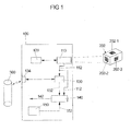
- FIG. 1 shows a block diagram of a device 100 for locating a mobile terminal in a location area.
- the device 100 is for example in the mobile Terminal, like one in the FIG. 2 or FIG. 3 shown smartphone 400, implemented. Subsequently, both on the FIG. 1 , the FIG. 2 and the FIG. 3 Referenced.
- a camera unit 110 of the device 100 occasionally or continuously provides still images of the current environment of the device 100 to a detector 120.
- a detector 120 detects in the still images provided by the camera unit 110 a landmark 202 located in the current environment.
- the landmark 202 can be designed in two dimensions, for example in the form of an imprint on a wall, or three-dimensional, as shown in FIG FIG. 1 is shown. It is advantageous if the landmark 202 is made visually distinctive, so that the detection for the detector 120 is simplified. In addition, each landmark should be installed so that it is clearly visible from as many positions in the local area as possible. It is also conceivable, for example, that the landmark (similar to a lamp) is suspended, so that it can be easily detected by the camera unit.
- the size, the number and the spatial density of the landmarks to be installed depend on the area of the location area and the desired spatial resolution of the location.
- the landmark 202 has a number of uniquely identifiable and opto-electronically detectable characters 202-1, 202-2 and 202-3.
- a two-dimensional barcode such as a QR code or a DataMatrix code.
- Each of these characters are assigned the same or slightly different location data, which is the absolute position of the landmark 202 or the absolute position of the respective character 202-1; 202-2 or 202-3. This location data is contained in a database 300.
- the database 300 includes, for each character 202-1, 202-2 and 202-3, alignment data each indicating in which spatial direction the page of the landmark on which the character in question is mounted.
- the detector 120 detects the landmark 202 in the still image 112, it causes scanning of the barcode 202-2.
- the still image 112 generated by the camera unit 110 is fed to a comparator 130, which, for example, like the detector, is implemented in the form of an image processing unit.
- the comparator 130 determines from the still image 112 the identification of the landmark 200 and the character 202-2.
- the comparator 130 then accesses the database 300 via a link 134 to determine absolute location data and alignment data associated with the identification.
- the database 300 is implemented, for example, on a server (not shown) outside the device 100 and outside the mobile terminal 400. Access to this database 300 takes place, for example, via a mobile radio network present in the local area and / or a WLAN present in the local area and / or via another radio connection.
- the location and orientation data 132 determined by the comparator 130 and the still image from the landmark 202 generated by the camera unit 110 are fed to a computer 140 of the device 100.
- the computer 140 calculates, based on the still image 112 and the location and orientation data 132, a position 142 of the mobile terminal 400 within the location area. For example, the computer 140 first determines based on the still image 132 of the landmark 200 a position of the mobile terminal 400 relative to the landmark 200. To determine the relative position of the mobile terminal 400, the computer 140 extracts from the still image 132, for example, information about the following: a Surface occupying an image of the landmark 200 in the still image 132; a location of the image within the still image 132; and / or a perspective distortion of the figure. Using the absolute location data 132 and the orientation data of the landmark 200, the calculator 140 may then calculate the absolute position of the mobile terminal 400 within the location area.
- the device 100 may include a motion sensor 150 that provides additional data 152 about a current location and / or about an actual acceleration of the mobile device 400.
- a motion sensor 150 that provides additional data 152 about a current location and / or about an actual acceleration of the mobile device 400.
- the motion sensor 150 detects, for example, whether the mobile terminal is in the horizontal or vertical. If such a motion sensor is present, the computer 140 can determine the position of the mobile terminal 400, taking into account the additional data 152 generated by the motion sensor 150.
- the device 100 is particularly suitable for locating the mobile terminal 400 in an indoor area where reception of GPS data is not possible.
- an indoor area is shown in the form of a warehouse having a plurality of aisles and shelves with parcels or the like installed therein.
- the computer 140 may, based on the calculated position 142 on an audiovisual output device in the form of a display 410 of the mobile terminal 400, cause output of position-related content and / or services.
- an audiovisual output device in the form of a display 410 of the mobile terminal 400
- a kind of map 146 of the current environment of the mobile terminal is displayed on the display 410, and graphically highlights the calculated position 142 and / or the current direction of movement.
- the position-related contents / services are on the one hand a navigation instruction 146-1 and on the other hand a position-related advertising content 146-2.
- Such position-related contents / services can also be stored on a database and queried by the mobile terminal 400 with the device 100.
- the present invention supports the use of a so-called. Augmented reality mode on a mobile device.
- FIG. 4 illustrates by way of example and in simplified form a method for locating the mobile terminal 400 in a location area.
- a still image is generated from the location area.
- a second step 720 there is detected a landmark arranged in the location area and imaged in a generated still image.
- the generated still image is assigned location data from a database 300 (step 730).
- a location of the mobile terminal 400 within the location area is determined based on the generated still image and the location data associated therewith (step 740).
Landscapes
- Engineering & Computer Science (AREA)
- Radar, Positioning & Navigation (AREA)
- Remote Sensing (AREA)
- Physics & Mathematics (AREA)
- General Physics & Mathematics (AREA)
- Automation & Control Theory (AREA)
- Electromagnetism (AREA)
- Aviation & Aerospace Engineering (AREA)
- Computer Vision & Pattern Recognition (AREA)
- Theoretical Computer Science (AREA)
- Navigation (AREA)
Applications Claiming Priority (1)
| Application Number | Priority Date | Filing Date | Title |
|---|---|---|---|
| DE102012221921.8A DE102012221921B4 (de) | 2012-11-29 | 2012-11-29 | Orten eines mobilen Endgeräts unter Nutzung von optisch detektierbaren Landmarken |
Publications (3)
| Publication Number | Publication Date |
|---|---|
| EP2738519A2 true EP2738519A2 (de) | 2014-06-04 |
| EP2738519A3 EP2738519A3 (de) | 2016-05-18 |
| EP2738519B1 EP2738519B1 (de) | 2019-10-02 |
Family
ID=49554130
Family Applications (1)
| Application Number | Title | Priority Date | Filing Date |
|---|---|---|---|
| EP13192308.8A Active EP2738519B1 (de) | 2012-11-29 | 2013-11-11 | Orten eines mobilen Endgeräts unter Nutzung von optisch detektierbaren Landmarken |
Country Status (3)
| Country | Link |
|---|---|
| EP (1) | EP2738519B1 (ko) |
| DE (1) | DE102012221921B4 (ko) |
| ES (1) | ES2759977T3 (ko) |
Cited By (5)
| Publication number | Priority date | Publication date | Assignee | Title |
|---|---|---|---|---|
| EP3037837A1 (de) * | 2014-12-22 | 2016-06-29 | Deutsche Telekom AG | Verfahren und Positionsbestimmungssystem zum Bestimmen der Position wenigstens einer mobilen, eine digitale Bilderfassungseinrichtung aufweisenden Kommunikationseinrichtung |
| WO2018144429A1 (en) * | 2017-01-31 | 2018-08-09 | Saudi Arabian Oil Company | Auto-generation of map landmarks using sensor readable tags |
| CN110618680A (zh) * | 2019-09-09 | 2019-12-27 | 金鹏电子信息机器有限公司 | 一种基于人工智能的定向位移装置 |
| EP3640594A1 (de) * | 2018-10-17 | 2020-04-22 | Robert Bosch GmbH | System von künstlichen landmarken in einer umgebung zur verwendung für eine sensorgestützte lokalisierung von mobilen plattformen |
| CN117560638A (zh) * | 2024-01-10 | 2024-02-13 | 山东派蒙机电技术有限公司 | 应用于移动端通信系统的融合通信方法、装置及设备 |
Families Citing this family (2)
| Publication number | Priority date | Publication date | Assignee | Title |
|---|---|---|---|---|
| DE102019211871B4 (de) * | 2019-08-07 | 2021-04-22 | Siemens Schweiz Ag | Verfahren und Anordnung zur Darstellung von technischen Objekten |
| DE102020213111A1 (de) | 2020-10-16 | 2022-04-21 | FoP Consult GmbH | Verfahren und System zur Bestimmung einer Pose oder Position eines mobilen Endgeräts |
Citations (7)
| Publication number | Priority date | Publication date | Assignee | Title |
|---|---|---|---|---|
| DE10248534A1 (de) | 2002-10-14 | 2004-04-22 | T-Mobile Deutschland Gmbh | Verfahren zur genauen Positionsbestimmung eines mobilen Endgerätes |
| DE60018466T2 (de) | 1999-12-23 | 2005-12-29 | Nokia Corp. | Verfahren und system zur bereitsstellung von ortsinformation in einem drahtlosen kommunikationsnetz |
| US7558595B2 (en) | 2004-06-25 | 2009-07-07 | Sony Ericsson Mobile Communications Ab | Mobile terminals, methods, and program products that generate communication information based on characters recognized in image data |
| US7775437B2 (en) | 2006-06-01 | 2010-08-17 | Evryx Technologies, Inc. | Methods and devices for detecting linkable objects |
| US8144920B2 (en) | 2007-03-15 | 2012-03-27 | Microsoft Corporation | Automated location estimation using image analysis |
| US20120133506A1 (en) | 2010-11-25 | 2012-05-31 | Institute For Information Industry | Mobile positioning apparatus, server, and mobile positioning method thereof |
| WO2012114304A1 (en) | 2011-02-24 | 2012-08-30 | Sisvel Technology S.R.L. | Indoor locating mobile terminals in a mobile cellular telecommunication network |
Family Cites Families (3)
| Publication number | Priority date | Publication date | Assignee | Title |
|---|---|---|---|---|
| US6697761B2 (en) | 2000-09-19 | 2004-02-24 | Olympus Optical Co., Ltd. | Three-dimensional position/orientation sensing apparatus, information presenting system, and model error detecting system |
| JP2003111128A (ja) * | 2001-09-28 | 2003-04-11 | J-Phone East Co Ltd | 現在位置特定方法、現在位置情報提供方法、移動経路案内方法、位置情報管理システム及び情報通信端末 |
| US20110039573A1 (en) | 2009-08-13 | 2011-02-17 | Qualcomm Incorporated | Accessing positional information for a mobile station using a data code label |
-
2012
- 2012-11-29 DE DE102012221921.8A patent/DE102012221921B4/de not_active Expired - Fee Related
-
2013
- 2013-11-11 EP EP13192308.8A patent/EP2738519B1/de active Active
- 2013-11-11 ES ES13192308T patent/ES2759977T3/es active Active
Patent Citations (7)
| Publication number | Priority date | Publication date | Assignee | Title |
|---|---|---|---|---|
| DE60018466T2 (de) | 1999-12-23 | 2005-12-29 | Nokia Corp. | Verfahren und system zur bereitsstellung von ortsinformation in einem drahtlosen kommunikationsnetz |
| DE10248534A1 (de) | 2002-10-14 | 2004-04-22 | T-Mobile Deutschland Gmbh | Verfahren zur genauen Positionsbestimmung eines mobilen Endgerätes |
| US7558595B2 (en) | 2004-06-25 | 2009-07-07 | Sony Ericsson Mobile Communications Ab | Mobile terminals, methods, and program products that generate communication information based on characters recognized in image data |
| US7775437B2 (en) | 2006-06-01 | 2010-08-17 | Evryx Technologies, Inc. | Methods and devices for detecting linkable objects |
| US8144920B2 (en) | 2007-03-15 | 2012-03-27 | Microsoft Corporation | Automated location estimation using image analysis |
| US20120133506A1 (en) | 2010-11-25 | 2012-05-31 | Institute For Information Industry | Mobile positioning apparatus, server, and mobile positioning method thereof |
| WO2012114304A1 (en) | 2011-02-24 | 2012-08-30 | Sisvel Technology S.R.L. | Indoor locating mobile terminals in a mobile cellular telecommunication network |
Non-Patent Citations (1)
| Title |
|---|
| V. LEPETIT ET AL.: "International Journal of Computer Vision", 25 June 2008, SPRINGER SCIENCE + BUSINESS MEDIA, article "EPnP: An Accurate O(n) Solution to the PnP Problem" |
Cited By (7)
| Publication number | Priority date | Publication date | Assignee | Title |
|---|---|---|---|---|
| EP3037837A1 (de) * | 2014-12-22 | 2016-06-29 | Deutsche Telekom AG | Verfahren und Positionsbestimmungssystem zum Bestimmen der Position wenigstens einer mobilen, eine digitale Bilderfassungseinrichtung aufweisenden Kommunikationseinrichtung |
| WO2018144429A1 (en) * | 2017-01-31 | 2018-08-09 | Saudi Arabian Oil Company | Auto-generation of map landmarks using sensor readable tags |
| US10290137B2 (en) | 2017-01-31 | 2019-05-14 | Saudi Arabian Oil Company | Auto-generation of map landmarks using sensor readable tags |
| EP3640594A1 (de) * | 2018-10-17 | 2020-04-22 | Robert Bosch GmbH | System von künstlichen landmarken in einer umgebung zur verwendung für eine sensorgestützte lokalisierung von mobilen plattformen |
| CN110618680A (zh) * | 2019-09-09 | 2019-12-27 | 金鹏电子信息机器有限公司 | 一种基于人工智能的定向位移装置 |
| CN117560638A (zh) * | 2024-01-10 | 2024-02-13 | 山东派蒙机电技术有限公司 | 应用于移动端通信系统的融合通信方法、装置及设备 |
| CN117560638B (zh) * | 2024-01-10 | 2024-03-22 | 山东派蒙机电技术有限公司 | 应用于移动端通信系统的融合通信方法、装置及设备 |
Also Published As
| Publication number | Publication date |
|---|---|
| EP2738519B1 (de) | 2019-10-02 |
| DE102012221921B4 (de) | 2018-04-05 |
| ES2759977T3 (es) | 2020-05-12 |
| EP2738519A3 (de) | 2016-05-18 |
| DE102012221921A1 (de) | 2014-06-05 |
Similar Documents
| Publication | Publication Date | Title |
|---|---|---|
| EP2738519B1 (de) | Orten eines mobilen Endgeräts unter Nutzung von optisch detektierbaren Landmarken | |
| DE112010003324T5 (de) | RFID-Ortungssystem | |
| CN106233371A (zh) | 选择用于显示的时间分布的全景图像 | |
| US20140280199A1 (en) | System and Method for Determining and Maintaining Object Location and Status | |
| KR101983852B1 (ko) | 관람객의 인지범위를 고려한 전시공간분석 기반 전시회 서비스 제공 시스템 | |
| DE112018004395T5 (de) | Virtueller zugriff auf ein zugriffsbeschränktes objekt | |
| DE102018120510A1 (de) | Systeme und verfahren zur verkaufsstellenerkennung mit bildsensoren zur identifizierung neuer radiofrequenz- identifikations (rfid) -etiketten-ereignisse in der nähe eines rfid- lesegeräts | |
| CN103703758A (zh) | 移动增强现实系统 | |
| US11134193B2 (en) | Information processing system, information processing method, and non-transitory computer-readable storage medium | |
| US11520033B2 (en) | Techniques for determining a location of a mobile object | |
| JP2021519470A (ja) | 商品位置特定方法及び装置、デバイス、及び記憶媒体 | |
| DE112016001304T5 (de) | Detektieren des Ortes einer Mobilvorrichtung basierend auf semantischen Indikatoren | |
| US8724848B1 (en) | Locating objects using indicia | |
| KR20160009686A (ko) | 증강 현실 콘텐츠를 스크리닝하는 방법, 장치, 및 시스템 | |
| Zhang et al. | Seeing Eye Phone: a smart phone-based indoor localization and guidance system for the visually impaired | |
| EP3752986B1 (en) | Boundary maps for virtual reality systems | |
| DE102020209054A1 (de) | Vorrichtung und verfahren zur personenerkennung, -verfolgung und -identifizierung unter verwendung drahtloser signale und bilder | |
| CN104508706B (zh) | 特征提取方法、程序和系统 | |
| EP3711392B1 (de) | Verfahren und vorrichtung zur positionsbestimmung | |
| DE112021000762T5 (de) | Verfahren, system und vorrichtung zur mobilen ortung | |
| DE112018005119B4 (de) | Systeme und verfahren zum steuern eines oder mehrerer produktlesegeräte und zum bestimmen von produkteigenschaften | |
| CN105814606A (zh) | 基于图像的位置确定 | |
| EP3008636A1 (de) | Verfahren und system zum auffinden einer oder mehrerer personen durch ein fahrzeug | |
| EP3534293A1 (de) | Verfahren und vorrichtung zur ermittlung der position von objekten | |
| EP2287753A1 (de) | Verfahren zur informativen Beschreibung von Bildobjekten |
Legal Events
| Date | Code | Title | Description |
|---|---|---|---|
| PUAI | Public reference made under article 153(3) epc to a published international application that has entered the european phase |
Free format text: ORIGINAL CODE: 0009012 |
|
| 17P | Request for examination filed |
Effective date: 20131111 |
|
| AK | Designated contracting states |
Kind code of ref document: A2 Designated state(s): AL AT BE BG CH CY CZ DE DK EE ES FI FR GB GR HR HU IE IS IT LI LT LU LV MC MK MT NL NO PL PT RO RS SE SI SK SM TR |
|
| AX | Request for extension of the european patent |
Extension state: BA ME |
|
| PUAL | Search report despatched |
Free format text: ORIGINAL CODE: 0009013 |
|
| AK | Designated contracting states |
Kind code of ref document: A3 Designated state(s): AL AT BE BG CH CY CZ DE DK EE ES FI FR GB GR HR HU IE IS IT LI LT LU LV MC MK MT NL NO PL PT RO RS SE SI SK SM TR |
|
| AX | Request for extension of the european patent |
Extension state: BA ME |
|
| RIC1 | Information provided on ipc code assigned before grant |
Ipc: G06T 7/00 20060101ALI20160411BHEP Ipc: G01C 21/20 20060101AFI20160411BHEP Ipc: H04W 4/02 20090101ALI20160411BHEP |
|
| STAA | Information on the status of an ep patent application or granted ep patent |
Free format text: STATUS: REQUEST FOR EXAMINATION WAS MADE |
|
| R17P | Request for examination filed (corrected) |
Effective date: 20161103 |
|
| RBV | Designated contracting states (corrected) |
Designated state(s): AL AT BE BG CH CY CZ DE DK EE ES FI FR GB GR HR HU IE IS IT LI LT LU LV MC MK MT NL NO PL PT RO RS SE SI SK SM TR |
|
| STAA | Information on the status of an ep patent application or granted ep patent |
Free format text: STATUS: EXAMINATION IS IN PROGRESS |
|
| 17Q | First examination report despatched |
Effective date: 20170922 |
|
| RIC1 | Information provided on ipc code assigned before grant |
Ipc: G06T 7/73 20170101ALI20190312BHEP Ipc: G05D 1/02 20060101ALI20190312BHEP Ipc: H04W 4/02 20180101ALI20190312BHEP Ipc: G01C 21/20 20060101AFI20190312BHEP |
|
| GRAP | Despatch of communication of intention to grant a patent |
Free format text: ORIGINAL CODE: EPIDOSNIGR1 |
|
| STAA | Information on the status of an ep patent application or granted ep patent |
Free format text: STATUS: GRANT OF PATENT IS INTENDED |
|
| INTG | Intention to grant announced |
Effective date: 20190516 |
|
| RIN1 | Information on inventor provided before grant (corrected) |
Inventor name: VANDENHOUTEN, RALF |
|
| GRAS | Grant fee paid |
Free format text: ORIGINAL CODE: EPIDOSNIGR3 |
|
| GRAA | (expected) grant |
Free format text: ORIGINAL CODE: 0009210 |
|
| STAA | Information on the status of an ep patent application or granted ep patent |
Free format text: STATUS: THE PATENT HAS BEEN GRANTED |
|
| AK | Designated contracting states |
Kind code of ref document: B1 Designated state(s): AL AT BE BG CH CY CZ DE DK EE ES FI FR GB GR HR HU IE IS IT LI LT LU LV MC MK MT NL NO PL PT RO RS SE SI SK SM TR |
|
| REG | Reference to a national code |
Ref country code: GB Ref legal event code: FG4D Free format text: NOT ENGLISH |
|
| REG | Reference to a national code |
Ref country code: CH Ref legal event code: EP Ref country code: AT Ref legal event code: REF Ref document number: 1186681 Country of ref document: AT Kind code of ref document: T Effective date: 20191015 |
|
| REG | Reference to a national code |
Ref country code: DE Ref legal event code: R096 Ref document number: 502013013680 Country of ref document: DE |
|
| REG | Reference to a national code |
Ref country code: IE Ref legal event code: FG4D Free format text: LANGUAGE OF EP DOCUMENT: GERMAN |
|
| REG | Reference to a national code |
Ref country code: NL Ref legal event code: MP Effective date: 20191002 |
|
| REG | Reference to a national code |
Ref country code: LT Ref legal event code: MG4D |
|
| PG25 | Lapsed in a contracting state [announced via postgrant information from national office to epo] |
Ref country code: FI Free format text: LAPSE BECAUSE OF FAILURE TO SUBMIT A TRANSLATION OF THE DESCRIPTION OR TO PAY THE FEE WITHIN THE PRESCRIBED TIME-LIMIT Effective date: 20191002 Ref country code: BG Free format text: LAPSE BECAUSE OF FAILURE TO SUBMIT A TRANSLATION OF THE DESCRIPTION OR TO PAY THE FEE WITHIN THE PRESCRIBED TIME-LIMIT Effective date: 20200102 Ref country code: PT Free format text: LAPSE BECAUSE OF FAILURE TO SUBMIT A TRANSLATION OF THE DESCRIPTION OR TO PAY THE FEE WITHIN THE PRESCRIBED TIME-LIMIT Effective date: 20200203 Ref country code: SE Free format text: LAPSE BECAUSE OF FAILURE TO SUBMIT A TRANSLATION OF THE DESCRIPTION OR TO PAY THE FEE WITHIN THE PRESCRIBED TIME-LIMIT Effective date: 20191002 Ref country code: LV Free format text: LAPSE BECAUSE OF FAILURE TO SUBMIT A TRANSLATION OF THE DESCRIPTION OR TO PAY THE FEE WITHIN THE PRESCRIBED TIME-LIMIT Effective date: 20191002 Ref country code: NL Free format text: LAPSE BECAUSE OF FAILURE TO SUBMIT A TRANSLATION OF THE DESCRIPTION OR TO PAY THE FEE WITHIN THE PRESCRIBED TIME-LIMIT Effective date: 20191002 Ref country code: LT Free format text: LAPSE BECAUSE OF FAILURE TO SUBMIT A TRANSLATION OF THE DESCRIPTION OR TO PAY THE FEE WITHIN THE PRESCRIBED TIME-LIMIT Effective date: 20191002 Ref country code: GR Free format text: LAPSE BECAUSE OF FAILURE TO SUBMIT A TRANSLATION OF THE DESCRIPTION OR TO PAY THE FEE WITHIN THE PRESCRIBED TIME-LIMIT Effective date: 20200103 Ref country code: NO Free format text: LAPSE BECAUSE OF FAILURE TO SUBMIT A TRANSLATION OF THE DESCRIPTION OR TO PAY THE FEE WITHIN THE PRESCRIBED TIME-LIMIT Effective date: 20200102 Ref country code: PL Free format text: LAPSE BECAUSE OF FAILURE TO SUBMIT A TRANSLATION OF THE DESCRIPTION OR TO PAY THE FEE WITHIN THE PRESCRIBED TIME-LIMIT Effective date: 20191002 |
|
| REG | Reference to a national code |
Ref country code: ES Ref legal event code: FG2A Ref document number: 2759977 Country of ref document: ES Kind code of ref document: T3 Effective date: 20200512 |
|
| PG25 | Lapsed in a contracting state [announced via postgrant information from national office to epo] |
Ref country code: RS Free format text: LAPSE BECAUSE OF FAILURE TO SUBMIT A TRANSLATION OF THE DESCRIPTION OR TO PAY THE FEE WITHIN THE PRESCRIBED TIME-LIMIT Effective date: 20191002 Ref country code: HR Free format text: LAPSE BECAUSE OF FAILURE TO SUBMIT A TRANSLATION OF THE DESCRIPTION OR TO PAY THE FEE WITHIN THE PRESCRIBED TIME-LIMIT Effective date: 20191002 Ref country code: IS Free format text: LAPSE BECAUSE OF FAILURE TO SUBMIT A TRANSLATION OF THE DESCRIPTION OR TO PAY THE FEE WITHIN THE PRESCRIBED TIME-LIMIT Effective date: 20200224 Ref country code: CZ Free format text: LAPSE BECAUSE OF FAILURE TO SUBMIT A TRANSLATION OF THE DESCRIPTION OR TO PAY THE FEE WITHIN THE PRESCRIBED TIME-LIMIT Effective date: 20191002 |
|
| PG25 | Lapsed in a contracting state [announced via postgrant information from national office to epo] |
Ref country code: AL Free format text: LAPSE BECAUSE OF FAILURE TO SUBMIT A TRANSLATION OF THE DESCRIPTION OR TO PAY THE FEE WITHIN THE PRESCRIBED TIME-LIMIT Effective date: 20191002 |
|
| REG | Reference to a national code |
Ref country code: CH Ref legal event code: PL |
|
| REG | Reference to a national code |
Ref country code: DE Ref legal event code: R097 Ref document number: 502013013680 Country of ref document: DE |
|
| PG2D | Information on lapse in contracting state deleted |
Ref country code: IS |
|
| PG25 | Lapsed in a contracting state [announced via postgrant information from national office to epo] |
Ref country code: DK Free format text: LAPSE BECAUSE OF FAILURE TO SUBMIT A TRANSLATION OF THE DESCRIPTION OR TO PAY THE FEE WITHIN THE PRESCRIBED TIME-LIMIT Effective date: 20191002 Ref country code: MC Free format text: LAPSE BECAUSE OF FAILURE TO SUBMIT A TRANSLATION OF THE DESCRIPTION OR TO PAY THE FEE WITHIN THE PRESCRIBED TIME-LIMIT Effective date: 20191002 Ref country code: LI Free format text: LAPSE BECAUSE OF NON-PAYMENT OF DUE FEES Effective date: 20191130 Ref country code: CH Free format text: LAPSE BECAUSE OF NON-PAYMENT OF DUE FEES Effective date: 20191130 Ref country code: RO Free format text: LAPSE BECAUSE OF FAILURE TO SUBMIT A TRANSLATION OF THE DESCRIPTION OR TO PAY THE FEE WITHIN THE PRESCRIBED TIME-LIMIT Effective date: 20191002 Ref country code: EE Free format text: LAPSE BECAUSE OF FAILURE TO SUBMIT A TRANSLATION OF THE DESCRIPTION OR TO PAY THE FEE WITHIN THE PRESCRIBED TIME-LIMIT Effective date: 20191002 Ref country code: LU Free format text: LAPSE BECAUSE OF NON-PAYMENT OF DUE FEES Effective date: 20191111 Ref country code: IS Free format text: LAPSE BECAUSE OF FAILURE TO SUBMIT A TRANSLATION OF THE DESCRIPTION OR TO PAY THE FEE WITHIN THE PRESCRIBED TIME-LIMIT Effective date: 20200202 |
|
| PLBE | No opposition filed within time limit |
Free format text: ORIGINAL CODE: 0009261 |
|
| STAA | Information on the status of an ep patent application or granted ep patent |
Free format text: STATUS: NO OPPOSITION FILED WITHIN TIME LIMIT |
|
| REG | Reference to a national code |
Ref country code: BE Ref legal event code: MM Effective date: 20191130 |
|
| PG25 | Lapsed in a contracting state [announced via postgrant information from national office to epo] |
Ref country code: SK Free format text: LAPSE BECAUSE OF FAILURE TO SUBMIT A TRANSLATION OF THE DESCRIPTION OR TO PAY THE FEE WITHIN THE PRESCRIBED TIME-LIMIT Effective date: 20191002 Ref country code: SM Free format text: LAPSE BECAUSE OF FAILURE TO SUBMIT A TRANSLATION OF THE DESCRIPTION OR TO PAY THE FEE WITHIN THE PRESCRIBED TIME-LIMIT Effective date: 20191002 Ref country code: IT Free format text: LAPSE BECAUSE OF FAILURE TO SUBMIT A TRANSLATION OF THE DESCRIPTION OR TO PAY THE FEE WITHIN THE PRESCRIBED TIME-LIMIT Effective date: 20191002 |
|
| 26N | No opposition filed |
Effective date: 20200703 |
|
| PG25 | Lapsed in a contracting state [announced via postgrant information from national office to epo] |
Ref country code: IE Free format text: LAPSE BECAUSE OF NON-PAYMENT OF DUE FEES Effective date: 20191111 |
|
| PG25 | Lapsed in a contracting state [announced via postgrant information from national office to epo] |
Ref country code: BE Free format text: LAPSE BECAUSE OF NON-PAYMENT OF DUE FEES Effective date: 20191130 Ref country code: SI Free format text: LAPSE BECAUSE OF FAILURE TO SUBMIT A TRANSLATION OF THE DESCRIPTION OR TO PAY THE FEE WITHIN THE PRESCRIBED TIME-LIMIT Effective date: 20191002 |
|
| REG | Reference to a national code |
Ref country code: AT Ref legal event code: MM01 Ref document number: 1186681 Country of ref document: AT Kind code of ref document: T Effective date: 20191111 |
|
| PG25 | Lapsed in a contracting state [announced via postgrant information from national office to epo] |
Ref country code: AT Free format text: LAPSE BECAUSE OF NON-PAYMENT OF DUE FEES Effective date: 20191111 |
|
| PG25 | Lapsed in a contracting state [announced via postgrant information from national office to epo] |
Ref country code: CY Free format text: LAPSE BECAUSE OF FAILURE TO SUBMIT A TRANSLATION OF THE DESCRIPTION OR TO PAY THE FEE WITHIN THE PRESCRIBED TIME-LIMIT Effective date: 20191002 |
|
| PG25 | Lapsed in a contracting state [announced via postgrant information from national office to epo] |
Ref country code: HU Free format text: LAPSE BECAUSE OF FAILURE TO SUBMIT A TRANSLATION OF THE DESCRIPTION OR TO PAY THE FEE WITHIN THE PRESCRIBED TIME-LIMIT; INVALID AB INITIO Effective date: 20131111 Ref country code: MT Free format text: LAPSE BECAUSE OF FAILURE TO SUBMIT A TRANSLATION OF THE DESCRIPTION OR TO PAY THE FEE WITHIN THE PRESCRIBED TIME-LIMIT Effective date: 20191002 |
|
| PG25 | Lapsed in a contracting state [announced via postgrant information from national office to epo] |
Ref country code: TR Free format text: LAPSE BECAUSE OF FAILURE TO SUBMIT A TRANSLATION OF THE DESCRIPTION OR TO PAY THE FEE WITHIN THE PRESCRIBED TIME-LIMIT Effective date: 20191002 |
|
| PG25 | Lapsed in a contracting state [announced via postgrant information from national office to epo] |
Ref country code: MK Free format text: LAPSE BECAUSE OF FAILURE TO SUBMIT A TRANSLATION OF THE DESCRIPTION OR TO PAY THE FEE WITHIN THE PRESCRIBED TIME-LIMIT Effective date: 20191002 |
|
| PGFP | Annual fee paid to national office [announced via postgrant information from national office to epo] |
Ref country code: GB Payment date: 20231123 Year of fee payment: 11 |
|
| PGFP | Annual fee paid to national office [announced via postgrant information from national office to epo] |
Ref country code: ES Payment date: 20231215 Year of fee payment: 11 |
|
| PGFP | Annual fee paid to national office [announced via postgrant information from national office to epo] |
Ref country code: FR Payment date: 20231124 Year of fee payment: 11 Ref country code: DE Payment date: 20231213 Year of fee payment: 11 |