EP2738434A2 - Zero-moment fitting - Google Patents
Zero-moment fitting Download PDFInfo
- Publication number
- EP2738434A2 EP2738434A2 EP13194194.0A EP13194194A EP2738434A2 EP 2738434 A2 EP2738434 A2 EP 2738434A2 EP 13194194 A EP13194194 A EP 13194194A EP 2738434 A2 EP2738434 A2 EP 2738434A2
- Authority
- EP
- European Patent Office
- Prior art keywords
- bearing
- housing
- fluid conduit
- spherical
- spherical bearing
- Prior art date
- Legal status (The legal status is an assumption and is not a legal conclusion. Google has not performed a legal analysis and makes no representation as to the accuracy of the status listed.)
- Granted
Links
Images

Classifications
-
- F—MECHANICAL ENGINEERING; LIGHTING; HEATING; WEAPONS; BLASTING
- F16—ENGINEERING ELEMENTS AND UNITS; GENERAL MEASURES FOR PRODUCING AND MAINTAINING EFFECTIVE FUNCTIONING OF MACHINES OR INSTALLATIONS; THERMAL INSULATION IN GENERAL
- F16L—PIPES; JOINTS OR FITTINGS FOR PIPES; SUPPORTS FOR PIPES, CABLES OR PROTECTIVE TUBING; MEANS FOR THERMAL INSULATION IN GENERAL
- F16L39/00—Joints or fittings for double-walled or multi-channel pipes or pipe assemblies
-
- F—MECHANICAL ENGINEERING; LIGHTING; HEATING; WEAPONS; BLASTING
- F16—ENGINEERING ELEMENTS AND UNITS; GENERAL MEASURES FOR PRODUCING AND MAINTAINING EFFECTIVE FUNCTIONING OF MACHINES OR INSTALLATIONS; THERMAL INSULATION IN GENERAL
- F16L—PIPES; JOINTS OR FITTINGS FOR PIPES; SUPPORTS FOR PIPES, CABLES OR PROTECTIVE TUBING; MEANS FOR THERMAL INSULATION IN GENERAL
- F16L5/00—Devices for use where pipes, cables or protective tubing pass through walls or partitions
-
- F—MECHANICAL ENGINEERING; LIGHTING; HEATING; WEAPONS; BLASTING
- F16—ENGINEERING ELEMENTS AND UNITS; GENERAL MEASURES FOR PRODUCING AND MAINTAINING EFFECTIVE FUNCTIONING OF MACHINES OR INSTALLATIONS; THERMAL INSULATION IN GENERAL
- F16L—PIPES; JOINTS OR FITTINGS FOR PIPES; SUPPORTS FOR PIPES, CABLES OR PROTECTIVE TUBING; MEANS FOR THERMAL INSULATION IN GENERAL
- F16L27/00—Adjustable joints; Joints allowing movement
- F16L27/02—Universal joints, i.e. with mechanical connection allowing angular movement or adjustment of the axes of the parts in any direction
- F16L27/023—Universal and rotating joints
-
- B—PERFORMING OPERATIONS; TRANSPORTING
- B23—MACHINE TOOLS; METAL-WORKING NOT OTHERWISE PROVIDED FOR
- B23P—METAL-WORKING NOT OTHERWISE PROVIDED FOR; COMBINED OPERATIONS; UNIVERSAL MACHINE TOOLS
- B23P11/00—Connecting or disconnecting metal parts or objects by metal-working techniques not otherwise provided for
-
- F—MECHANICAL ENGINEERING; LIGHTING; HEATING; WEAPONS; BLASTING
- F16—ENGINEERING ELEMENTS AND UNITS; GENERAL MEASURES FOR PRODUCING AND MAINTAINING EFFECTIVE FUNCTIONING OF MACHINES OR INSTALLATIONS; THERMAL INSULATION IN GENERAL
- F16C—SHAFTS; FLEXIBLE SHAFTS; ELEMENTS OR CRANKSHAFT MECHANISMS; ROTARY BODIES OTHER THAN GEARING ELEMENTS; BEARINGS
- F16C23/00—Bearings for exclusively rotary movement adjustable for aligning or positioning
- F16C23/02—Sliding-contact bearings
- F16C23/04—Sliding-contact bearings self-adjusting
- F16C23/043—Sliding-contact bearings self-adjusting with spherical surfaces, e.g. spherical plain bearings
- F16C23/045—Sliding-contact bearings self-adjusting with spherical surfaces, e.g. spherical plain bearings for radial load mainly, e.g. radial spherical plain bearings
- F16C23/046—Sliding-contact bearings self-adjusting with spherical surfaces, e.g. spherical plain bearings for radial load mainly, e.g. radial spherical plain bearings with split outer rings
-
- F—MECHANICAL ENGINEERING; LIGHTING; HEATING; WEAPONS; BLASTING
- F16—ENGINEERING ELEMENTS AND UNITS; GENERAL MEASURES FOR PRODUCING AND MAINTAINING EFFECTIVE FUNCTIONING OF MACHINES OR INSTALLATIONS; THERMAL INSULATION IN GENERAL
- F16L—PIPES; JOINTS OR FITTINGS FOR PIPES; SUPPORTS FOR PIPES, CABLES OR PROTECTIVE TUBING; MEANS FOR THERMAL INSULATION IN GENERAL
- F16L5/00—Devices for use where pipes, cables or protective tubing pass through walls or partitions
- F16L5/02—Sealing
- F16L5/025—Sealing the pipe being movable
-
- Y—GENERAL TAGGING OF NEW TECHNOLOGICAL DEVELOPMENTS; GENERAL TAGGING OF CROSS-SECTIONAL TECHNOLOGIES SPANNING OVER SEVERAL SECTIONS OF THE IPC; TECHNICAL SUBJECTS COVERED BY FORMER USPC CROSS-REFERENCE ART COLLECTIONS [XRACs] AND DIGESTS
- Y10—TECHNICAL SUBJECTS COVERED BY FORMER USPC
- Y10T—TECHNICAL SUBJECTS COVERED BY FORMER US CLASSIFICATION
- Y10T29/00—Metal working
- Y10T29/49—Method of mechanical manufacture
- Y10T29/49636—Process for making bearing or component thereof
-
- Y—GENERAL TAGGING OF NEW TECHNOLOGICAL DEVELOPMENTS; GENERAL TAGGING OF CROSS-SECTIONAL TECHNOLOGIES SPANNING OVER SEVERAL SECTIONS OF THE IPC; TECHNICAL SUBJECTS COVERED BY FORMER USPC CROSS-REFERENCE ART COLLECTIONS [XRACs] AND DIGESTS
- Y10—TECHNICAL SUBJECTS COVERED BY FORMER USPC
- Y10T—TECHNICAL SUBJECTS COVERED BY FORMER US CLASSIFICATION
- Y10T29/00—Metal working
- Y10T29/49—Method of mechanical manufacture
- Y10T29/49826—Assembling or joining
- Y10T29/49947—Assembling or joining by applying separate fastener
- Y10T29/49948—Multipart cooperating fastener [e.g., bolt and nut]
Definitions
- Aircraft and other vehicles commonly have various fluid conduits (e.g., fuel lines, hydraulic lines, air lines, etc) extending throughout the vehicle. These conduits may traverse bulkheads and other structures as they route fluid between source and destination locations. The conduits are typically routed through openings in the bulkheads and secured to the bulkheads at these locations with fittings to prevent abrasion and other damage to the fluid conduits that could occur due to contact between the conduit and the bulkhead.
- fluid conduits e.g., fuel lines, hydraulic lines, air lines, etc
- Fuel lines and other fluid conduits are often pressurized. As pressurized fluids travel through the conduits, the geometry or configuration of the lines and the various couplings associated with the fluid conduits creates various loads and moments that may be transferred to the bulkheads or to the fittings that attach the fluid conduits to the bulkheads. Pulse loads or shear loads that align with a central axis of the fluid conduit may not be problematic. However, loads that create a twisting of the fluid conduit around the central axis or at a non-zero angle with respect to the central axis provide a moment on the fitting and/or bulkhead. These moments may lead to fatigue or failure of the fitting over time.
- a structural fitting may include a spherical bearing and a bearing housing.
- the spherical bearing may include a conduit aperture for receiving a fluid conduit through the spherical bearing.
- the bearing housing may be configured to retain the spherical bearing within the bearing housing, to allow for rotation of the spherical bearing within the bearing housing, and to be attached to a structure to secure the bearing housing and the spherical bearing to the structure.
- a method for securing a fluid conduit to a structure includes encompassing the fluid conduit with a spherical bearing.
- the spherical bearing is secured within a bearing housing, which is secured to the structure.
- the spherical bearing is retaining within the housing while allowing for the rotation of the spherical bearing within the housing, eliminating any moments from being applied to the housing and corresponding structure.
- a system for securing a fluid conduit may include first and second portions of the fluid conduit, a spherical bearing that includes a front bearing and a rear bearing, and a bearing housing.
- the first and second portions of the fluid conduit each include a coupling flange with fastener apertures.
- the coupling flanges abut one another to couple the two portions of the fluid conduit with fasteners via the fastener apertures.
- the front and rear bearings each encompass corresponding first and second portions of the fluid conduit.
- the front and rear bearings abut against one another, encompassing the fluid conduit and securing the fasteners coupling the first and second portions of the fluid conduit via the coupling flanges.
- the assembled spherical bearing is positioned within the bearing housing, which may be coupled to the structure.
- the bearing housing retains the spherical bearing while allowing for rotation of the spherical bearing within the bearing housing.
- fluid conduits are often routed through bulkheads and other structures.
- fittings are typically used to secure the fluid conduit to the structure as the conduit passes through.
- a load or moment may be created on the traditional fitting used to secure the fluid conduit to the structure. This undesirable moment may result in premature fatigue or failure of the fitting or fluid conduit at that location.
- a zero-moment fitting may be used to allow for rotational movement of the fluid conduit around a longitudinal axis of the conduit without imposing a corresponding load and moment on the fitting.
- a fitting may include a housing that is coupled to the structure.
- a spherical bearing encompasses the fluid conduit and rests within the housing without being fixedly attached to the housing. Any rotational movement of the fluid conduit creates a corresponding rotational movement of the spherical bearing. However, because the spherical bearing is allowed to rotate freely within the housing, there is no associated load or moment imposed on the fitting as a result of the rotational movement of the fluid conduit and spherical bearing.
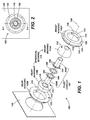
- FIGURE 1 an exploded view of an example of a zero-moment fitting 100 with a fluid conduit 102 and the structure 140 to which the fluid conduit 102 is to be attached are shown.
- the fluid conduit 102 may include a first portion 102A and a second portion 102B being joined together at or near the structure 140.
- the fluid conduit 102 may be a pressurized fuel line passing through the structure 140, which may be an aircraft bulkhead or wing spar.
- the first portion 102A and the second portion 102B of the fluid conduit 102 may each include a coupling flange 104.
- Each coupling flange may have any number of fastener apertures 106 for receiving fasteners for coupling the two portions together.
- a coupling gasket 108 having corresponding apertures may be used between the coupling flanges 104 of the first portion 102A and the second portion 102B to prevent fluid leakage from the fluid conduit 102 when assembled.
- a spherical bearing 110 may include two sections for ease of assembly, specifically a front bearing 110A and a rear bearing 110B.
- the front bearing 110A and the rear bearing 110B each include a bearing inner face 114 that will abut the corresponding opposing bearing inner face 114 to mate the front bearing 110A and the rear bearing 110B and create an assembled configuration of the spherical bearing 110.
- the exterior bearing surface 118 is shaped such that the spherical bearing 110 is approximately spherical when assembled.
- the material of the spherical bearing, and of the bearing housing 120 described below, may be any suitable material according to the operational loads for which the zero-moment fitting 100 will experience while minimizing weight and wear that may occur due to the friction between the spherical bearing 110 and the bearing housing 120.
- Example materials include but are not limited to CuNiSn or AlNiBr compounds or other suitable materials for the spherical bearing 110 and 15Cr-5Ni stainless steel or other suitable materials for the bearing housing 120.
- the spherical bearing 110 additionally includes a conduit aperture 112 sized to receive the fluid conduit 102 within.
- the fluid conduit 102 passes through the approximate center of the spherical bearing 110 parallel with a longitudinal axis 150 extending through the zero-moment fitting 100.
- the front bearing 110A and/or the rear bearing 110B may include a number of fastener cavities 116 for receiving a front or rear portion of a fastener extending through the coupling flange 104 of the first or second portion of the fluid conduit 102.
- One or both of the front bearing 110A and the rear bearing 110B may additionally include a flange cavity (not shown in FIGURE 1 ) configured to receive all or a portion of the coupling flange 104. In doing so, rotational movement of the fluid conduit 102 around the longitudinal axis 150, or angular rotation with respect to the longitudinal axis 150, will allow for the spherical bearing 110 to rotate with the fluid conduit 102 within the bearing housing 120.
- the bearing housing 120 may include two sections for assembly purposes, specifically the front housing 120A and the rear housing 120B. These two sections may be identical components arranged to face one another such that an inside face 122 of the front housing 120A (not shown) will abut an inside face 122 of the rear housing 120B when assembled.
- Each of the front housing 120A and the rear housing 120B may have an inside face 122 and an outside face 128 opposite the inside face.
- the inside face may include an annular inner bearing edge 130, while the outside face may include an annular outer bearing edge 132.
- the surface defined between the annular inner bearing edge 130 and the annular outer bearing edge 132 may be referred to as the bearing retention surface 134, as this surface abuts the exterior bearing surface 118 and retains the spherical bearing 110 within the bearing housing 120.
- the diameter of the annular outer bearing edge 132 may be smaller than the diameter of the annular inner bearing edge 130.
- the diameter of the annular inner bearing edge 130 may be approximately equivalent to, or slightly larger than, the diameter of the spherical bearing 110.
- the front housing 120A and the rear housing 120B may be mated together with the spherical bearing 110 in between.
- the smaller diameters of the annular outer bearing edges 132 of the front and rear housings prevent the spherical bearing 110 from exiting either the front housing 120A or the rear housing 120B, effectively retaining the spherical bearing 110 within the zero-moment fitting 100.
- the bearing retention surface 134 of the front housing 120A and of the rear housing 120B abut the exterior bearing surface 118 of the spherical bearing 110 when the zero-moment fitting 100 is in the assembled configuration.
- the bearing retention surface 134 between the annular inner bearing edge 130 and the annular outer bearing edge 132 of each of the front housing 120A and the rear housing 120B may be shaped such that the slope between the inner and the outer edge is linear or straight, or may be shaped such that the slope is arcuate or curved.
- An arcuate shape of the bearing retention surface 134 may substantially correspond to the external shape of the spherical bearing 118.
- the bearing housing 120 may additionally include a fitting flange 124 for securing the zero-moment fitting 100 to a structure 140.
- the fitting flange 124 may be configured as an annular flange as shown in FIGURE 1 , or may alternatively be configured as any number of tabs (not shown) extending from the inside face 122.
- the fitting flange 124 may include any number of fastener apertures 126 for receiving fasteners to secure the bearing housing 120 to the vehicle bulkhead or other structure 140.
- the fitting flange 124 may have a recessed groove (not shown) for receiving an o-ring for preventing fluid from escaping through the structure 140 when the zero-moment fitting 100 is used in a wet environment such as within a tank of fluid.
- FIGURE 2 shows a front view of the zero-moment fitting 100.
- the spherical bearing 110 has been hatched to distinguish the bearing from the bearing housing 120 for clarity purposes. From this view, the fluid conduit 102 can be seen traversing the center of the spherical bearing 110.
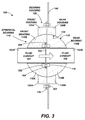
- FIGURE 3 shows a cross-sectional view of one embodiment of the zero-moment fitting 100 taken along line A-A of FIGURE 2 .
- fluid flows through the fluid conduit 102 from one side of the structure 140 to the opposite side of the structure 140.
- the first portion 102A of the fluid conduit 102 is coupled to the second portion 102B via fasteners 302.
- the fasteners 302 may include any suitable conventional type of fastener.
- a bearing gasket 108 may be used between the coupling flanges 104 of the first portion 102A and the second portion 102B.
- the front bearing 110A and the rear bearing 110B encompass the fluid conduit 102 and abut one another to create the spherical bearing 110.
- the front bearing 110A and the rear bearing 110B may include fastener cavities 116 for receiving a portion of the fasteners 302 that secure the two portions of the fluid conduit 102.
- One or both of the front bearing 110A and the rear bearing 110B may additionally include a flange cavity 304 for receiving the coupling flange 104 while allowing the bearing inner faces 114 of the front bearing 110A and rear bearing 110B to abut one another.
- the bearing housing 120 is shown in FIGURE 3 in the assembled configuration in which the front housing 120A is coupled to the rear housing 120B with the spherical bearing 110 retained within.
- the bearing housing 120 includes a bearing retention surface 134 that is shaped according to the exterior bearing surface 118.
- the spherical bearing 110 according to the disclosure herein is allowed to rotate within the bearing housing 120. In doing so, the bearing housing 120 remains free from rotational loads and corresponding moments that may damage or destroy a traditional fitting.
- the bearing housing 120 is fixedly attached to the structure 140 via the fitting flange 124 and corresponding fasteners 302.
- FIGURE 4 an illustrative routine 400 for securing a fluid conduit 102 to a structure 140 will now be described in detail. It should be appreciated that more or fewer operations may be performed than shown in the figures and described herein. These operations may also be performed in a different order than those described herein.
- the routine 400 begins at operation 402, where the first portion 102A of the fluid conduit 102 is coupled to the second portion 102B via fasteners 302.
- the coupling may include sandwiching a bearing gasket 108 between coupling flanges 104 of the first portion 102A and the second portion 102A of the fluid conduit 102.
- Fasteners 302 may be threaded or otherwise positioned within fastener apertures 106 of the coupling flanges 104 and bearing gasket 108.
- the routine 400 continues to operation 404, where the fluid conduit 102 is encompassed by the spherical bearing.
- the front bearing 110A is threaded onto the first portion 102A of the fluid conduit 102
- the rear bearing 110B is threaded onto the second portion 102B of the fluid conduit 102.
- the coupling flange 104 and corresponding fasteners 302 associated with the fluid conduit 102 may be positioned within the flange cavity 304 and fastener cavities 116 of one or both of the front bearing 110A and the rear bearing 110B.
- the bearing inner faces 114 of the front bearing 110A and the rear bearing 110B are positioned against one another to assemble the spherical bearing 110.
- the front housing 120A is positioned on one side of the spherical bearing 110 with the fluid conduit 102 traversing through the housing and the rear housing 120B is similarly positioned on the opposing side of the spherical bearing 110.
- the front housing 120A and the rear housing 120B are moved inward until the inside faces 122 of the front housing 120A and the rear housing 120B abut one another with the spherical bearing 110 positioned within the bearing housing 120 against the bearing retention surface 134.
- the routine 400 continues from operation 406 to operation 408, where the assembled housing is placed against the structure 140 and secured to the structure utilizing the fitting flange 124 of the bearing housing 120 and corresponding fasteners 302. After operation 408, the zero-moment fitting 100 is assembled and installed, securing the fluid conduit 102 to the structure 140 while allowing for rotational movement of the fluid conduit 102.
- the routine 400 ends.
Landscapes
- Engineering & Computer Science (AREA)
- General Engineering & Computer Science (AREA)
- Mechanical Engineering (AREA)
- Joints Allowing Movement (AREA)
- Support Of The Bearing (AREA)
- Pivots And Pivotal Connections (AREA)
Abstract
Description
- Aircraft and other vehicles commonly have various fluid conduits (e.g., fuel lines, hydraulic lines, air lines, etc) extending throughout the vehicle. These conduits may traverse bulkheads and other structures as they route fluid between source and destination locations. The conduits are typically routed through openings in the bulkheads and secured to the bulkheads at these locations with fittings to prevent abrasion and other damage to the fluid conduits that could occur due to contact between the conduit and the bulkhead.
- Fuel lines and other fluid conduits are often pressurized. As pressurized fluids travel through the conduits, the geometry or configuration of the lines and the various couplings associated with the fluid conduits creates various loads and moments that may be transferred to the bulkheads or to the fittings that attach the fluid conduits to the bulkheads. Pulse loads or shear loads that align with a central axis of the fluid conduit may not be problematic. However, loads that create a twisting of the fluid conduit around the central axis or at a non-zero angle with respect to the central axis provide a moment on the fitting and/or bulkhead. These moments may lead to fatigue or failure of the fitting over time.
- It is with respect to these considerations and others that the disclosure made herein is presented.
- It should be appreciated that this Summary is provided to introduce a selection of concepts in a simplified form that are further described below in the Detailed Description. This Summary is not intended to be used to limit the scope of the claimed subject matter.
- Apparatus, systems, and methods provide for a zero-moment fitting, or a fitting that allows for the rotation of a fluid conduit around a central axis without applying an undesirable moment on the corresponding fitting and structure to which the fitting is attached. According to one aspect of the disclosure provided herein, a structural fitting may include a spherical bearing and a bearing housing. The spherical bearing may include a conduit aperture for receiving a fluid conduit through the spherical bearing. The bearing housing may be configured to retain the spherical bearing within the bearing housing, to allow for rotation of the spherical bearing within the bearing housing, and to be attached to a structure to secure the bearing housing and the spherical bearing to the structure.
- Further embodiments of this structural fitting are defined in dependent claims 2-10. According to another aspect, a method for securing a fluid conduit to a structure includes encompassing the fluid conduit with a spherical bearing. The spherical bearing is secured within a bearing housing, which is secured to the structure. In doing so, the spherical bearing is retaining within the housing while allowing for the rotation of the spherical bearing within the housing, eliminating any moments from being applied to the housing and corresponding structure.
- Further embodiments of this method form the subject-matter of dependent claims 12-15. According to yet another aspect, a system for securing a fluid conduit may include first and second portions of the fluid conduit, a spherical bearing that includes a front bearing and a rear bearing, and a bearing housing. The first and second portions of the fluid conduit each include a coupling flange with fastener apertures. The coupling flanges abut one another to couple the two portions of the fluid conduit with fasteners via the fastener apertures. The front and rear bearings each encompass corresponding first and second portions of the fluid conduit. The front and rear bearings abut against one another, encompassing the fluid conduit and securing the fasteners coupling the first and second portions of the fluid conduit via the coupling flanges. The assembled spherical bearing is positioned within the bearing housing, which may be coupled to the structure. The bearing housing retains the spherical bearing while allowing for rotation of the spherical bearing within the bearing housing.
- Further, the disclosure comprises embodiments according to the following clauses:
- Clause 15. A system for securing a fluid conduit to a structure, comprising:
- a first portion of the fluid conduit comprising a first coupling flange having a plurality of first fastener apertures;
- a second portion of the fluid conduit comprising a second coupling flange having a plurality of second fastener apertures, wherein the second coupling flange is configured to abut the first coupling flange such that the plurality of first fastener apertures aligns with the plurality of second fastener apertures;
- a spherical bearing comprising a front bearing and a rear bearing,
wherein the front bearing is configured to encompass the first portion of the fluid conduit and to secure a plurality of fasteners projecting through the plurality of first fastener apertures, and
wherein the rear bearing is configured to encompass the second portion of the fluid conduit, to secure the plurality of fasteners projecting through the plurality of second fastener apertures, and to abut the front bearing to create an assembled bearing configuration having the fluid conduit traversing through the spherical bearing; and - a bearing housing configured to retain the spherical bearing within the bearing housing, to allow for rotation of the spherical bearing within the bearing housing, and to fixedly couple the bearing housing to the structure.
- Clause 16. The system of clause 15, wherein the bearing housing comprises a front housing and a rear housing configured to abut one another to create an assembled housing configuration, the assembled housing configuration comprising an inside surface shaped to maintain the assembled bearing configuration of the spherical bearing while allowing rotation of the spherical bearing within the bearing housing.
- Clause 17. The system of clause 16, wherein each of the front housing and the rear housing comprises:
- an inside face configured to mate with the inside face of a corresponding front housing or rear housing, the inside face comprising an annular inner bearing edge;
- an outside face opposite the inside face and external to the bearing housing in the assembled housing configuration, the outside face comprising an annular outer bearing edge having a smaller diameter than a diameter of the annular inner bearing edge; and
- a bearing retention surface defined between the annular inner bearing edge and the annular outer bearing edge.
- Clause 18. The system of clause 17, wherein the bearing retention surface comprises an arcuate shape between the annular inner bearing edge and the annular outer bearing edge that substantially corresponds to an external shape of the spherical bearing.
- Clause 19. The system of clause 15, further comprising a coupling gasket sized according to the first coupling flange and the second coupling flange, and configured for positioning between the first coupling flange and the second coupling flange when assembled to prevent fluid from escaping the fluid conduit.
- Clause 20. The system of clause 15, wherein the bearing housing comprises a fitting flange comprising a fastener aperture configured to receive a fastener for fixedly coupling the bearing housing to the structure.
- The features, functions, and advantages that have been discussed can be achieved independently in various embodiments of the present disclosure or may be combined in yet other embodiments, further details of which can be seen with reference to the following description and drawings.
-
-
FIGURE 1 is a top perspective exploded view of an example of a zero-moment fitting with a fluid conduit and the structure to which the fluid conduit is to be attached according to various embodiments presented herein; -
FIGURE 2 is a front view of a zero-moment fitting securing a fluid conduit to a structure according to various embodiments presented herein; -
FIGURE 3 is a cross-sectional view taken along line A-A of the zero-moment fitting ofFIGURE 2 according to various embodiments presented herein; and -
FIGURE 4 is a process flow diagram illustrating a method for securing a fluid conduit to a structure according to various embodiments presented herein. - The following detailed description is directed to a zero-moment fitting, system, and methods for securing a fluid conduit to a structure. As discussed briefly above, fluid conduits are often routed through bulkheads and other structures. In doing so, fittings are typically used to secure the fluid conduit to the structure as the conduit passes through. However, as pressurized fluids travel through the fluid conduit, due to the geometry of some conventional fluid conduits and associated couplings, a load or moment may be created on the traditional fitting used to secure the fluid conduit to the structure. This undesirable moment may result in premature fatigue or failure of the fitting or fluid conduit at that location.
- Utilizing the concepts described herein, a zero-moment fitting may be used to allow for rotational movement of the fluid conduit around a longitudinal axis of the conduit without imposing a corresponding load and moment on the fitting. As will be described in detail below, a fitting according to various embodiments may include a housing that is coupled to the structure. A spherical bearing encompasses the fluid conduit and rests within the housing without being fixedly attached to the housing. Any rotational movement of the fluid conduit creates a corresponding rotational movement of the spherical bearing. However, because the spherical bearing is allowed to rotate freely within the housing, there is no associated load or moment imposed on the fitting as a result of the rotational movement of the fluid conduit and spherical bearing.
- In the following detailed description, references are made to the accompanying drawings that form a part hereof, and which are shown by way of illustration, specific embodiments, or examples. Referring now to the drawings, in which like numerals represent like elements through the several figures, the zero-moment fitting will be described. Turning to
FIGURE 1 , an exploded view of an example of a zero-moment fitting 100 with afluid conduit 102 and thestructure 140 to which thefluid conduit 102 is to be attached are shown. Thefluid conduit 102 may include afirst portion 102A and asecond portion 102B being joined together at or near thestructure 140. According to one illustrative embodiment, thefluid conduit 102 may be a pressurized fuel line passing through thestructure 140, which may be an aircraft bulkhead or wing spar. - The
first portion 102A and thesecond portion 102B of thefluid conduit 102 may each include acoupling flange 104. Each coupling flange may have any number offastener apertures 106 for receiving fasteners for coupling the two portions together. Acoupling gasket 108 having corresponding apertures may be used between thecoupling flanges 104 of thefirst portion 102A and thesecond portion 102B to prevent fluid leakage from thefluid conduit 102 when assembled. - A
spherical bearing 110 may include two sections for ease of assembly, specifically afront bearing 110A and arear bearing 110B. Thefront bearing 110A and therear bearing 110B each include a bearinginner face 114 that will abut the corresponding opposing bearinginner face 114 to mate the front bearing 110A and therear bearing 110B and create an assembled configuration of thespherical bearing 110. Theexterior bearing surface 118 is shaped such that thespherical bearing 110 is approximately spherical when assembled. The material of the spherical bearing, and of the bearinghousing 120 described below, may be any suitable material according to the operational loads for which the zero-moment fitting 100 will experience while minimizing weight and wear that may occur due to the friction between thespherical bearing 110 and the bearinghousing 120. Example materials include but are not limited to CuNiSn or AlNiBr compounds or other suitable materials for thespherical bearing 110 and 15Cr-5Ni stainless steel or other suitable materials for the bearinghousing 120. - The
spherical bearing 110 additionally includes aconduit aperture 112 sized to receive thefluid conduit 102 within. Thefluid conduit 102 passes through the approximate center of thespherical bearing 110 parallel with alongitudinal axis 150 extending through the zero-moment fitting 100. To secure thefluid conduit 102 within thespherical bearing 110, thefront bearing 110A and/or therear bearing 110B may include a number offastener cavities 116 for receiving a front or rear portion of a fastener extending through thecoupling flange 104 of the first or second portion of thefluid conduit 102. One or both of the front bearing 110A and therear bearing 110B may additionally include a flange cavity (not shown inFIGURE 1 ) configured to receive all or a portion of thecoupling flange 104. In doing so, rotational movement of thefluid conduit 102 around thelongitudinal axis 150, or angular rotation with respect to thelongitudinal axis 150, will allow for thespherical bearing 110 to rotate with thefluid conduit 102 within the bearinghousing 120. - The bearing
housing 120 may include two sections for assembly purposes, specifically thefront housing 120A and therear housing 120B. These two sections may be identical components arranged to face one another such that aninside face 122 of thefront housing 120A (not shown) will abut aninside face 122 of therear housing 120B when assembled. Each of thefront housing 120A and therear housing 120B may have aninside face 122 and anoutside face 128 opposite the inside face. The inside face may include an annularinner bearing edge 130, while the outside face may include an annularouter bearing edge 132. The surface defined between the annularinner bearing edge 130 and the annularouter bearing edge 132 may be referred to as the bearingretention surface 134, as this surface abuts theexterior bearing surface 118 and retains thespherical bearing 110 within the bearinghousing 120. - According to various embodiments, the diameter of the annular
outer bearing edge 132 may be smaller than the diameter of the annularinner bearing edge 130. According to one embodiment, the diameter of the annularinner bearing edge 130 may be approximately equivalent to, or slightly larger than, the diameter of thespherical bearing 110. In this manner, thefront housing 120A and therear housing 120B may be mated together with thespherical bearing 110 in between. The smaller diameters of the annular outer bearing edges 132 of the front and rear housings prevent thespherical bearing 110 from exiting either thefront housing 120A or therear housing 120B, effectively retaining thespherical bearing 110 within the zero-moment fitting 100. - As previously stated, the bearing
retention surface 134 of thefront housing 120A and of therear housing 120B abut theexterior bearing surface 118 of thespherical bearing 110 when the zero-moment fitting 100 is in the assembled configuration. It should be appreciated that the bearingretention surface 134 between the annularinner bearing edge 130 and the annularouter bearing edge 132 of each of thefront housing 120A and therear housing 120B may be shaped such that the slope between the inner and the outer edge is linear or straight, or may be shaped such that the slope is arcuate or curved. An arcuate shape of the bearingretention surface 134 may substantially correspond to the external shape of thespherical bearing 118. - The bearing
housing 120 may additionally include afitting flange 124 for securing the zero-moment fitting 100 to astructure 140. Thefitting flange 124 may be configured as an annular flange as shown inFIGURE 1 , or may alternatively be configured as any number of tabs (not shown) extending from theinside face 122. Thefitting flange 124 may include any number offastener apertures 126 for receiving fasteners to secure the bearinghousing 120 to the vehicle bulkhead orother structure 140. Moreover, thefitting flange 124 may have a recessed groove (not shown) for receiving an o-ring for preventing fluid from escaping through thestructure 140 when the zero-moment fitting 100 is used in a wet environment such as within a tank of fluid. - Turning now to
FIGURES 2 and3 , a zero-moment fitting 100 in an assembled configuration and attached to astructure 140 will now be discussed.FIGURE 2 shows a front view of the zero-moment fitting 100. Thespherical bearing 110 has been hatched to distinguish the bearing from the bearinghousing 120 for clarity purposes. From this view, thefluid conduit 102 can be seen traversing the center of thespherical bearing 110. -
FIGURE 3 shows a cross-sectional view of one embodiment of the zero-moment fitting 100 taken along line A-A ofFIGURE 2 . As indicated by the open arrow, fluid flows through thefluid conduit 102 from one side of thestructure 140 to the opposite side of thestructure 140. Thefirst portion 102A of thefluid conduit 102 is coupled to thesecond portion 102B viafasteners 302. Thefasteners 302 may include any suitable conventional type of fastener. A bearinggasket 108 may be used between thecoupling flanges 104 of thefirst portion 102A and thesecond portion 102B. - As discussed above, the front bearing 110A and the
rear bearing 110B encompass thefluid conduit 102 and abut one another to create thespherical bearing 110. Thefront bearing 110A and therear bearing 110B may includefastener cavities 116 for receiving a portion of thefasteners 302 that secure the two portions of thefluid conduit 102. One or both of the front bearing 110A and therear bearing 110B may additionally include aflange cavity 304 for receiving thecoupling flange 104 while allowing the bearinginner faces 114 of thefront bearing 110A and rear bearing 110B to abut one another. - The bearing
housing 120 is shown inFIGURE 3 in the assembled configuration in which thefront housing 120A is coupled to therear housing 120B with thespherical bearing 110 retained within. As shown, the bearinghousing 120 includes a bearingretention surface 134 that is shaped according to theexterior bearing surface 118. When thefluid conduit 102 moves and rotates in a manner that would traditionally create an undesirable load on the fitting secured to thestructure 140, thespherical bearing 110 according to the disclosure herein is allowed to rotate within the bearinghousing 120. In doing so, the bearinghousing 120 remains free from rotational loads and corresponding moments that may damage or destroy a traditional fitting. The bearinghousing 120 is fixedly attached to thestructure 140 via thefitting flange 124 andcorresponding fasteners 302. - Turning now to
FIGURE 4 , anillustrative routine 400 for securing afluid conduit 102 to astructure 140 will now be described in detail. It should be appreciated that more or fewer operations may be performed than shown in the figures and described herein. These operations may also be performed in a different order than those described herein. - The routine 400 begins at
operation 402, where thefirst portion 102A of thefluid conduit 102 is coupled to thesecond portion 102B viafasteners 302. The coupling may include sandwiching a bearinggasket 108 betweencoupling flanges 104 of thefirst portion 102A and thesecond portion 102A of thefluid conduit 102.Fasteners 302 may be threaded or otherwise positioned withinfastener apertures 106 of thecoupling flanges 104 and bearinggasket 108. - From
operation 402, the routine 400 continues tooperation 404, where thefluid conduit 102 is encompassed by the spherical bearing. To do so, the front bearing 110A is threaded onto thefirst portion 102A of thefluid conduit 102, while therear bearing 110B is threaded onto thesecond portion 102B of thefluid conduit 102. Thecoupling flange 104 andcorresponding fasteners 302 associated with thefluid conduit 102 may be positioned within theflange cavity 304 andfastener cavities 116 of one or both of the front bearing 110A and therear bearing 110B. The bearinginner faces 114 of the front bearing 110A and therear bearing 110B are positioned against one another to assemble thespherical bearing 110. - At
operation 406, thefront housing 120A is positioned on one side of thespherical bearing 110 with thefluid conduit 102 traversing through the housing and therear housing 120B is similarly positioned on the opposing side of thespherical bearing 110. Thefront housing 120A and therear housing 120B are moved inward until the inside faces 122 of thefront housing 120A and therear housing 120B abut one another with thespherical bearing 110 positioned within the bearinghousing 120 against the bearingretention surface 134. - The routine 400 continues from
operation 406 tooperation 408, where the assembled housing is placed against thestructure 140 and secured to the structure utilizing thefitting flange 124 of the bearinghousing 120 andcorresponding fasteners 302. Afteroperation 408, the zero-moment fitting 100 is assembled and installed, securing thefluid conduit 102 to thestructure 140 while allowing for rotational movement of thefluid conduit 102. The routine 400 ends. - Based on the foregoing, it should be appreciated that technologies for securing a fluid conduit to a structure in a manner that eliminates the undesirable moment on a traditional fitting created at least in part as a result of pressurized fluid travelling through various conduit geometries through a vehicle. The subject matter described above is provided by way of illustration only and should not be construed as limiting. Various modifications and changes may be made to the subject matter described herein without following the example embodiments and applications illustrated and described, and without departing from the true spirit and scope of the present disclosure, which is set forth in the following claims.
Claims (15)
- A structural fitting (100), comprising:a spherical bearing (110) comprising a conduit aperture (112) configured to receive a fluid conduit (102) traversing the spherical bearing (110); anda bearing housing (120) configured to retain the spherical bearing (110) within the bearing housing (120), to allow for rotation of the spherical bearing (110) within the bearing housing (120), and to be fixedly coupled to a structure (140).
- The structural fitting (100) of claim 1, wherein the spherical bearing (110) further comprises a front bearing (110x) and a rear bearing (110B), wherein the front bearing (110x) and the rear bearing (110B) are configured to abut one another to create an assembled bearing configuration having the conduit aperture (112).
- The structural fitting (100) of claim 1 or 2, wherein the bearing housing (120) comprises a front housing (120A) and a rear housing (120B) configured to abut one another to create an assembled housing configuration, the assembled housing configuration comprising an inside face (122) shaped to maintain the assembled bearing configuration of the spherical bearing (110) while allowing rotation of the spherical bearing (110) within the bearing housing (120).
- The structural fitting (100) of claim 3, wherein each of the front housing (120A) and the rear housing (120B) comprises:an inside face (122) configured to mate with the inside face (122) of a corresponding front housing (120A) or rear housing (120B), the inside face (122) comprising an annular inner bearing edge (130);an outside face (128) opposite the inside face (122) and external to the bearing housing (120) in the assembled housing configuration, the outside face (128) comprising an annular outer bearing edge (132) having a smaller diameter than a diameter of the annular inner bearing edge (130); anda bearing retention surface (134) defined between the annular inner bearing edge (130) and the annular outer bearing edge (132).
- The structural fitting (100) of claim 4, wherein the bearing retention surface (134) comprises an arcuate shape between the annular inner bearing edge (130) and the annular outer bearing edge (132) that substantially corresponds to an external shape of the spherical bearing (110).
- The structural fitting (100) of any of claims 2 to 5, wherein at least one of the front bearing (110x) and the rear bearing (110B) is configured to engage an assembled coupling flange coupling front (102A) and rear portions (102B) of the fluid conduit (102) within the conduit aperture (112) such that the assembled bearing configuration secures the fluid conduit (102) within the spherical bearing (110).
- The structural fitting (100) of any of claims 2 to 6, wherein the front bearing (110x) and the rear bearing (110B) comprise a plurality of fastener cavities (116), each of the fastener cavities (116) configured for receiving a portion of a fastener from the assembled coupling flange coupling the front (102A) and rear (102B) portions of the fluid conduit (102).
- The structural fitting (100) of any of claims 1 to 7, wherein the bearing housing (120) comprises a fitting flange (124) comprising a fastener aperture (126) configured to receive a fastener (302) for coupling the bearing housing (120) to the structure (140).
- The structural fitting (100) of any of claims 1 to 8, wherein the fluid conduit (102) comprises a fluid line and wherein the structure (140) comprises a bulkhead of a vehicle.
- The structural fitting (100) of any of claims 1 to 9, wherein the fluid conduit (102) comprises:a first portion (102A) of the fluid conduit (102) comprising a first coupling flange (104) having a plurality of first fastener apertures (106);a second portion (102B) of the fluid conduit (102) comprising a second coupling flange (104) having a plurality of second fastener apertures (106), wherein the second coupling flange (104) is configured to abut the first coupling flange (104) such that the plurality of first fastener apertures (106) aligns with the plurality of second fastener apertures (106);a spherical bearing (110) comprising a front bearing (110A) and a rear bearing (110B),
wherein the front bearing (110x) is configured to encompass the first portion (102A) of the fluid conduit (102) and to secure a plurality of fasteners projecting through the plurality of first fastener apertures (106), and
wherein the rear bearing (110B) is configured to encompass the second portion (102B) of the fluid conduit (102), to secure the plurality of fasteners projecting through the plurality of second fastener apertures (106), and to abut the front bearing (110A) to create an assembled bearing configuration having the fluid conduit (102) traversing through the spherical bearing (110);a bearing housing (120) comprising a front housing (120A) and a rear housing (120B) configured to abut one another to create an assembled housing configuration and configured to retain the spherical bearing (110) within the bearing housing (120), to allow for rotation of the spherical bearing (110) within the bearing housing (120), and to fixedly couple the bearing housing (120) to the structure (140); anda coupling gasket (108) sized according to the first coupling flange (104) and the second coupling flange (104), and configured for positioning between the first coupling flange (104) and the second coupling flange (104) when assembled to prevent fluid from escaping the fluid conduit (102). - A method for securing a fluid conduit (102) to a structure (140), comprising:encompassing the fluid conduit (102) with a spherical bearing (110);securing the spherical bearing (110) within a bearing housing (120) such that the spherical bearing (110) is retained within the bearing housing (120) while allowing for rotation of the spherical bearing (110) within the bearing housing (120); andsecuring the bearing housing (120) to the structure (140).
- The method of claim 11, further comprising:coupling a first portion (102A) of the fluid conduit (102) to a second portion (102B) of the fluid conduit (102) via a first coupling flange (104) of the first portion (102A) and a second coupling flange (104) of the second portion (102B) and a plurality of fasteners to create an assembled coupling flange of the fluid conduit (102), wherein encompassing the fluid conduit (102) with the spherical bearing (110) comprises positioning the assembled coupling flange within corresponding flange and fastener cavities (116) of the spherical bearing (110).
- The method of claim 11 or 12, wherein the bearing housing (120) comprises a front housing (120A) and a rear housing (120B), and wherein securing the spherical bearing (110) within the bearing housing (120) such that the spherical bearing (110) is retained within the bearing housing (120) while allowing for rotation of the spherical bearing (110) within the bearing housing (120) comprises:positioning the spherical bearing (110) within the front housing (120A); andpositioning the spherical bearing (110) within the rear housing (120B) such that an inside face (122) of the front housing (120A) abuts an inside face (122) of the rear housing (120B), encompassing the spherical bearing (110) such that an exterior bearing surface (118) of the spherical bearing (110) abuts a bearing retention surface (134) defined by the front housing (120A) and the rear housing (120B) and configured to allow for rotational movement of the spherical bearing (110) with respect to the bearing retention surface (134).
- The method of any of claims 11 to 13, further comprising securing the front housing (120A) to the rear housing (120B).
- The method of any of claims 11 to 14, wherein securing the front housing (120A) to the rear housing (120B) and securing the bearing housing (120) to the structure (140) comprises installing a plurality of fasteners (302) through a plurality of fastener apertures (126) such that each fastener aperture (126) and corresponding fastener traverses the front housing (120A), the rear housing (120B), and the structure (140).
Applications Claiming Priority (1)
| Application Number | Priority Date | Filing Date | Title |
|---|---|---|---|
| US13/688,807 US9574683B2 (en) | 2012-11-29 | 2012-11-29 | Zero-moment fitting |
Publications (3)
| Publication Number | Publication Date |
|---|---|
| EP2738434A2 true EP2738434A2 (en) | 2014-06-04 |
| EP2738434A3 EP2738434A3 (en) | 2016-07-06 |
| EP2738434B1 EP2738434B1 (en) | 2019-08-14 |
Family
ID=49758999
Family Applications (1)
| Application Number | Title | Priority Date | Filing Date |
|---|---|---|---|
| EP13194194.0A Active EP2738434B1 (en) | 2012-11-29 | 2013-11-25 | Zero-moment fitting |
Country Status (7)
| Country | Link |
|---|---|
| US (1) | US9574683B2 (en) |
| EP (1) | EP2738434B1 (en) |
| JP (1) | JP6473565B2 (en) |
| CN (1) | CN103851271B (en) |
| CA (1) | CA2831513C (en) |
| ES (1) | ES2753991T3 (en) |
| RU (1) | RU2653620C9 (en) |
Cited By (3)
| Publication number | Priority date | Publication date | Assignee | Title |
|---|---|---|---|---|
| GB2521922A (en) * | 2013-11-15 | 2015-07-08 | Tekmar Energy Ltd | Mounting arrangement for offshore structure |
| GB2577518A (en) * | 2018-09-26 | 2020-04-01 | Jdr Cable Systems Ltd | Termination assembly |
| IT201900001823A1 (en) * | 2019-02-08 | 2020-08-08 | Wallmax S R L | CABLE GUIDE GROUP. |
Families Citing this family (9)
| Publication number | Priority date | Publication date | Assignee | Title |
|---|---|---|---|---|
| RU169837U1 (en) * | 2016-07-15 | 2017-04-04 | Чи-Вэнь ЧЭНЬ | FITTING DESIGN FOR GAS SUPPLY |
| US20180187819A1 (en) * | 2017-01-05 | 2018-07-05 | Salco Products, Inc. | Attachment flange assembly and method |
| CN108050080B (en) * | 2017-12-28 | 2024-10-29 | 宙斯流体系统(上海)有限公司 | Complete supercharging device based on pump in quiet high-speed pipe |
| CN108483066A (en) * | 2018-02-02 | 2018-09-04 | 五邑大学 | A kind of connection angle angle regulation method |
| GB2576701C (en) * | 2018-08-15 | 2023-03-29 | Short Brothers Plc | Electrical isolator fitting |
| CN112273352B (en) * | 2020-10-26 | 2022-07-22 | 江苏大学 | Liquid medicine and electric energy multiplexing conveying device |
| US20250361020A1 (en) * | 2022-06-14 | 2025-11-27 | Airbus Operations Limited | An aircraft assembly |
| GB2632619A (en) * | 2022-11-25 | 2025-02-19 | Airbus Operations Ltd | Aircraft assembly |
| US12471249B2 (en) * | 2023-04-11 | 2025-11-11 | Quanta Computer Inc. | Liquid cooling system with rotatable joint |
Family Cites Families (18)
| Publication number | Priority date | Publication date | Assignee | Title |
|---|---|---|---|---|
| US2329529A (en) | 1942-06-26 | 1943-09-14 | Jr Joseph M Gwinn | Adjustable cable guide |
| US2788203A (en) | 1952-08-22 | 1957-04-09 | Goodman Mfg Co | Hose guide and aligning means for transmitting fluid under pressure over the roll-over joint of a kerf cutting machine |
| US3018078A (en) | 1960-01-21 | 1962-01-23 | Holdren Brothers Inc | Device for mounting a conduit to a tank |
| JPS506251B1 (en) * | 1970-01-19 | 1975-03-12 | ||
| SU621938A1 (en) * | 1976-05-24 | 1978-08-30 | Предприятие П/Я В-2616 | Universal joint of pipelines |
| US4098527A (en) * | 1977-01-21 | 1978-07-04 | Murdock Machine & Engineering Company | Tension bearing connector |
| JPH04107515U (en) * | 1991-02-28 | 1992-09-17 | エヌテイエヌ株式会社 | Spherical plain bearing |
| US5205768A (en) | 1991-08-01 | 1993-04-27 | Imodco, Inc. | Multiple fluid swivel arrangement |
| JPH0674451U (en) * | 1993-03-30 | 1994-10-21 | 日野自動車工業株式会社 | Air duct attachment part |
| US5588511A (en) | 1995-05-15 | 1996-12-31 | Sargent & Lundy | Seismic pipe restraint and method for using the same |
| US6070835A (en) | 1998-03-19 | 2000-06-06 | Qualcomm Incorporated | Ball-compression grommet |
| CA2254188A1 (en) * | 1998-11-20 | 2000-05-20 | Bruce Gradwell | Vacuum hose to tool swivel connector |
| GB0329267D0 (en) | 2003-12-17 | 2004-01-21 | Structural Science Ltd | Pipe seal |
| CN2682261Y (en) * | 2004-03-19 | 2005-03-02 | 叶国荣 | Connecting device between tap and cold/hot water pipe built in wall |
| US20050247346A1 (en) | 2004-05-07 | 2005-11-10 | Edward Pentz | Hose mount |
| EP2013526B1 (en) * | 2006-04-19 | 2013-11-20 | Taimi R&D INC. | Multifunctionally swivelling coupling assembly for fluid lines |
| US7930827B2 (en) * | 2006-05-22 | 2011-04-26 | Moxee Innovations Corporation | Split bearing and method of making the same |
| JP5737903B2 (en) | 2010-10-26 | 2015-06-17 | 三菱重工業株式会社 | Piping support structure for aircraft |
-
2012
- 2012-11-29 US US13/688,807 patent/US9574683B2/en active Active
-
2013
- 2013-10-29 CA CA2831513A patent/CA2831513C/en active Active
- 2013-11-25 EP EP13194194.0A patent/EP2738434B1/en active Active
- 2013-11-25 ES ES13194194T patent/ES2753991T3/en active Active
- 2013-11-27 JP JP2013244595A patent/JP6473565B2/en active Active
- 2013-11-28 RU RU2013152984A patent/RU2653620C9/en active
- 2013-11-29 CN CN201310629627.9A patent/CN103851271B/en active Active
Non-Patent Citations (1)
| Title |
|---|
| None |
Cited By (4)
| Publication number | Priority date | Publication date | Assignee | Title |
|---|---|---|---|---|
| GB2521922A (en) * | 2013-11-15 | 2015-07-08 | Tekmar Energy Ltd | Mounting arrangement for offshore structure |
| GB2577518A (en) * | 2018-09-26 | 2020-04-01 | Jdr Cable Systems Ltd | Termination assembly |
| US11346390B2 (en) | 2018-09-26 | 2022-05-31 | Jdr Cable Systems Ltd. | Termination assembly |
| IT201900001823A1 (en) * | 2019-02-08 | 2020-08-08 | Wallmax S R L | CABLE GUIDE GROUP. |
Also Published As
| Publication number | Publication date |
|---|---|
| CN103851271B (en) | 2017-05-17 |
| RU2653620C9 (en) | 2018-10-17 |
| CN103851271A (en) | 2014-06-11 |
| RU2013152984A (en) | 2015-06-10 |
| JP2014111987A (en) | 2014-06-19 |
| US9574683B2 (en) | 2017-02-21 |
| US20140144002A1 (en) | 2014-05-29 |
| JP6473565B2 (en) | 2019-02-20 |
| EP2738434B1 (en) | 2019-08-14 |
| CA2831513A1 (en) | 2014-05-29 |
| RU2653620C2 (en) | 2018-05-11 |
| ES2753991T3 (en) | 2020-04-15 |
| EP2738434A3 (en) | 2016-07-06 |
| CA2831513C (en) | 2017-08-01 |
Similar Documents
| Publication | Publication Date | Title |
|---|---|---|
| CA2831513C (en) | Zero-moment fitting | |
| US8800921B2 (en) | Structural component and fuselage of an aircraft or spacecraft | |
| US10384759B2 (en) | Pressure bulkhead for an aircraft fuselage | |
| US9248901B2 (en) | Airframe structural element | |
| EP2045503A2 (en) | Shrouded coupling assemblies for conduits | |
| EP3620702B1 (en) | Pipe support | |
| EP2921727B1 (en) | U-shaped clip for fixing a link rod within an aircraft clevis | |
| US10794522B2 (en) | Flexible double walled hose connection | |
| US20150285418A1 (en) | Joint for tube | |
| CA2929764A1 (en) | A pressure bulkhead for an aircraft fuselage, and an aircraft comprising such a pressure bulkhead | |
| US10604247B2 (en) | Tension torsion strap | |
| CN109250067B (en) | Quick Release Wings and Unmanned Aerial Vehicles | |
| EP3524832A1 (en) | Fastener | |
| US10780981B2 (en) | Aircraft seat rail mounting member | |
| US11434015B2 (en) | Aircraft engine attachment comprising at least one fork-type system for immobilizing a shear pin in translation, method for mounting said engine attachment and aircraft comprising said engine attachment | |
| US20150330533A1 (en) | Suspension system especially for underwater cable | |
| US11519538B2 (en) | Coupling assembly to connect first and second conduits | |
| EP3378781B1 (en) | Fume tight sock collector/box | |
| CN114537685A (en) | Fuel system, kit of parts, aircraft and method for manufacturing an aircraft | |
| US12097966B2 (en) | Fuel pipe assembly | |
| CN111071428B (en) | Bulkhead connector assembly | |
| EP3181976B1 (en) | Rotary joint for connecting hydraulic pipes and hydraulic piping with rotary joints | |
| RU2718337C1 (en) | Pass-through support-rotary assembly (3 versions) | |
| US20200255120A1 (en) | Rotorcraft service fixtures | |
| RU2539273C2 (en) | Device to mount and demount replaceable unit of pneumatic hydraulic system and device for its assembly |
Legal Events
| Date | Code | Title | Description |
|---|---|---|---|
| PUAI | Public reference made under article 153(3) epc to a published international application that has entered the european phase |
Free format text: ORIGINAL CODE: 0009012 |
|
| 17P | Request for examination filed |
Effective date: 20131125 |
|
| AK | Designated contracting states |
Kind code of ref document: A2 Designated state(s): AL AT BE BG CH CY CZ DE DK EE ES FI FR GB GR HR HU IE IS IT LI LT LU LV MC MK MT NL NO PL PT RO RS SE SI SK SM TR |
|
| AX | Request for extension of the european patent |
Extension state: BA ME |
|
| PUAL | Search report despatched |
Free format text: ORIGINAL CODE: 0009013 |
|
| AK | Designated contracting states |
Kind code of ref document: A3 Designated state(s): AL AT BE BG CH CY CZ DE DK EE ES FI FR GB GR HR HU IE IS IT LI LT LU LV MC MK MT NL NO PL PT RO RS SE SI SK SM TR |
|
| AX | Request for extension of the european patent |
Extension state: BA ME |
|
| RIC1 | Information provided on ipc code assigned before grant |
Ipc: F16L 5/02 20060101ALI20160602BHEP Ipc: F16C 23/04 20060101ALI20160602BHEP Ipc: B23P 11/00 20060101ALI20160602BHEP Ipc: F16L 5/00 20060101ALI20160602BHEP Ipc: F16L 27/02 20060101AFI20160602BHEP |
|
| STAA | Information on the status of an ep patent application or granted ep patent |
Free format text: STATUS: REQUEST FOR EXAMINATION WAS MADE |
|
| STAA | Information on the status of an ep patent application or granted ep patent |
Free format text: STATUS: EXAMINATION IS IN PROGRESS |
|
| 17Q | First examination report despatched |
Effective date: 20171011 |
|
| GRAP | Despatch of communication of intention to grant a patent |
Free format text: ORIGINAL CODE: EPIDOSNIGR1 |
|
| STAA | Information on the status of an ep patent application or granted ep patent |
Free format text: STATUS: GRANT OF PATENT IS INTENDED |
|
| INTG | Intention to grant announced |
Effective date: 20190308 |
|
| GRAS | Grant fee paid |
Free format text: ORIGINAL CODE: EPIDOSNIGR3 |
|
| GRAA | (expected) grant |
Free format text: ORIGINAL CODE: 0009210 |
|
| STAA | Information on the status of an ep patent application or granted ep patent |
Free format text: STATUS: THE PATENT HAS BEEN GRANTED |
|
| AK | Designated contracting states |
Kind code of ref document: B1 Designated state(s): AL AT BE BG CH CY CZ DE DK EE ES FI FR GB GR HR HU IE IS IT LI LT LU LV MC MK MT NL NO PL PT RO RS SE SI SK SM TR |
|
| REG | Reference to a national code |
Ref country code: GB Ref legal event code: FG4D |
|
| REG | Reference to a national code |
Ref country code: CH Ref legal event code: EP Ref country code: AT Ref legal event code: REF Ref document number: 1167442 Country of ref document: AT Kind code of ref document: T Effective date: 20190815 |
|
| REG | Reference to a national code |
Ref country code: DE Ref legal event code: R096 Ref document number: 602013059087 Country of ref document: DE |
|
| REG | Reference to a national code |
Ref country code: IE Ref legal event code: FG4D |
|
| REG | Reference to a national code |
Ref country code: NL Ref legal event code: MP Effective date: 20190814 |
|
| REG | Reference to a national code |
Ref country code: LT Ref legal event code: MG4D |
|
| PG25 | Lapsed in a contracting state [announced via postgrant information from national office to epo] |
Ref country code: FI Free format text: LAPSE BECAUSE OF FAILURE TO SUBMIT A TRANSLATION OF THE DESCRIPTION OR TO PAY THE FEE WITHIN THE PRESCRIBED TIME-LIMIT Effective date: 20190814 Ref country code: LT Free format text: LAPSE BECAUSE OF FAILURE TO SUBMIT A TRANSLATION OF THE DESCRIPTION OR TO PAY THE FEE WITHIN THE PRESCRIBED TIME-LIMIT Effective date: 20190814 Ref country code: NL Free format text: LAPSE BECAUSE OF FAILURE TO SUBMIT A TRANSLATION OF THE DESCRIPTION OR TO PAY THE FEE WITHIN THE PRESCRIBED TIME-LIMIT Effective date: 20190814 Ref country code: BG Free format text: LAPSE BECAUSE OF FAILURE TO SUBMIT A TRANSLATION OF THE DESCRIPTION OR TO PAY THE FEE WITHIN THE PRESCRIBED TIME-LIMIT Effective date: 20191114 Ref country code: NO Free format text: LAPSE BECAUSE OF FAILURE TO SUBMIT A TRANSLATION OF THE DESCRIPTION OR TO PAY THE FEE WITHIN THE PRESCRIBED TIME-LIMIT Effective date: 20191114 Ref country code: PT Free format text: LAPSE BECAUSE OF FAILURE TO SUBMIT A TRANSLATION OF THE DESCRIPTION OR TO PAY THE FEE WITHIN THE PRESCRIBED TIME-LIMIT Effective date: 20191216 Ref country code: HR Free format text: LAPSE BECAUSE OF FAILURE TO SUBMIT A TRANSLATION OF THE DESCRIPTION OR TO PAY THE FEE WITHIN THE PRESCRIBED TIME-LIMIT Effective date: 20190814 Ref country code: SE Free format text: LAPSE BECAUSE OF FAILURE TO SUBMIT A TRANSLATION OF THE DESCRIPTION OR TO PAY THE FEE WITHIN THE PRESCRIBED TIME-LIMIT Effective date: 20190814 |
|
| REG | Reference to a national code |
Ref country code: AT Ref legal event code: MK05 Ref document number: 1167442 Country of ref document: AT Kind code of ref document: T Effective date: 20190814 |
|
| PG25 | Lapsed in a contracting state [announced via postgrant information from national office to epo] |
Ref country code: IS Free format text: LAPSE BECAUSE OF FAILURE TO SUBMIT A TRANSLATION OF THE DESCRIPTION OR TO PAY THE FEE WITHIN THE PRESCRIBED TIME-LIMIT Effective date: 20191214 Ref country code: RS Free format text: LAPSE BECAUSE OF FAILURE TO SUBMIT A TRANSLATION OF THE DESCRIPTION OR TO PAY THE FEE WITHIN THE PRESCRIBED TIME-LIMIT Effective date: 20190814 Ref country code: GR Free format text: LAPSE BECAUSE OF FAILURE TO SUBMIT A TRANSLATION OF THE DESCRIPTION OR TO PAY THE FEE WITHIN THE PRESCRIBED TIME-LIMIT Effective date: 20191115 Ref country code: LV Free format text: LAPSE BECAUSE OF FAILURE TO SUBMIT A TRANSLATION OF THE DESCRIPTION OR TO PAY THE FEE WITHIN THE PRESCRIBED TIME-LIMIT Effective date: 20190814 Ref country code: AL Free format text: LAPSE BECAUSE OF FAILURE TO SUBMIT A TRANSLATION OF THE DESCRIPTION OR TO PAY THE FEE WITHIN THE PRESCRIBED TIME-LIMIT Effective date: 20190814 |
|
| PG25 | Lapsed in a contracting state [announced via postgrant information from national office to epo] |
Ref country code: TR Free format text: LAPSE BECAUSE OF FAILURE TO SUBMIT A TRANSLATION OF THE DESCRIPTION OR TO PAY THE FEE WITHIN THE PRESCRIBED TIME-LIMIT Effective date: 20190814 |
|
| REG | Reference to a national code |
Ref country code: ES Ref legal event code: FG2A Ref document number: 2753991 Country of ref document: ES Kind code of ref document: T3 Effective date: 20200415 |
|
| PG25 | Lapsed in a contracting state [announced via postgrant information from national office to epo] |
Ref country code: EE Free format text: LAPSE BECAUSE OF FAILURE TO SUBMIT A TRANSLATION OF THE DESCRIPTION OR TO PAY THE FEE WITHIN THE PRESCRIBED TIME-LIMIT Effective date: 20190814 Ref country code: PL Free format text: LAPSE BECAUSE OF FAILURE TO SUBMIT A TRANSLATION OF THE DESCRIPTION OR TO PAY THE FEE WITHIN THE PRESCRIBED TIME-LIMIT Effective date: 20190814 Ref country code: AT Free format text: LAPSE BECAUSE OF FAILURE TO SUBMIT A TRANSLATION OF THE DESCRIPTION OR TO PAY THE FEE WITHIN THE PRESCRIBED TIME-LIMIT Effective date: 20190814 Ref country code: DK Free format text: LAPSE BECAUSE OF FAILURE TO SUBMIT A TRANSLATION OF THE DESCRIPTION OR TO PAY THE FEE WITHIN THE PRESCRIBED TIME-LIMIT Effective date: 20190814 Ref country code: RO Free format text: LAPSE BECAUSE OF FAILURE TO SUBMIT A TRANSLATION OF THE DESCRIPTION OR TO PAY THE FEE WITHIN THE PRESCRIBED TIME-LIMIT Effective date: 20190814 |
|
| PG25 | Lapsed in a contracting state [announced via postgrant information from national office to epo] |
Ref country code: SK Free format text: LAPSE BECAUSE OF FAILURE TO SUBMIT A TRANSLATION OF THE DESCRIPTION OR TO PAY THE FEE WITHIN THE PRESCRIBED TIME-LIMIT Effective date: 20190814 Ref country code: CZ Free format text: LAPSE BECAUSE OF FAILURE TO SUBMIT A TRANSLATION OF THE DESCRIPTION OR TO PAY THE FEE WITHIN THE PRESCRIBED TIME-LIMIT Effective date: 20190814 Ref country code: IS Free format text: LAPSE BECAUSE OF FAILURE TO SUBMIT A TRANSLATION OF THE DESCRIPTION OR TO PAY THE FEE WITHIN THE PRESCRIBED TIME-LIMIT Effective date: 20200224 Ref country code: SM Free format text: LAPSE BECAUSE OF FAILURE TO SUBMIT A TRANSLATION OF THE DESCRIPTION OR TO PAY THE FEE WITHIN THE PRESCRIBED TIME-LIMIT Effective date: 20190814 |
|
| REG | Reference to a national code |
Ref country code: DE Ref legal event code: R097 Ref document number: 602013059087 Country of ref document: DE |
|
| REG | Reference to a national code |
Ref country code: CH Ref legal event code: PL |
|
| PLBE | No opposition filed within time limit |
Free format text: ORIGINAL CODE: 0009261 |
|
| STAA | Information on the status of an ep patent application or granted ep patent |
Free format text: STATUS: NO OPPOSITION FILED WITHIN TIME LIMIT |
|
| PG2D | Information on lapse in contracting state deleted |
Ref country code: IS |
|
| PG25 | Lapsed in a contracting state [announced via postgrant information from national office to epo] |
Ref country code: MC Free format text: LAPSE BECAUSE OF FAILURE TO SUBMIT A TRANSLATION OF THE DESCRIPTION OR TO PAY THE FEE WITHIN THE PRESCRIBED TIME-LIMIT Effective date: 20190814 Ref country code: LI Free format text: LAPSE BECAUSE OF NON-PAYMENT OF DUE FEES Effective date: 20191130 Ref country code: CH Free format text: LAPSE BECAUSE OF NON-PAYMENT OF DUE FEES Effective date: 20191130 Ref country code: LU Free format text: LAPSE BECAUSE OF NON-PAYMENT OF DUE FEES Effective date: 20191125 |
|
| 26N | No opposition filed |
Effective date: 20200603 |
|
| REG | Reference to a national code |
Ref country code: BE Ref legal event code: MM Effective date: 20191130 |
|
| PG25 | Lapsed in a contracting state [announced via postgrant information from national office to epo] |
Ref country code: SI Free format text: LAPSE BECAUSE OF FAILURE TO SUBMIT A TRANSLATION OF THE DESCRIPTION OR TO PAY THE FEE WITHIN THE PRESCRIBED TIME-LIMIT Effective date: 20190814 |
|
| PG25 | Lapsed in a contracting state [announced via postgrant information from national office to epo] |
Ref country code: IE Free format text: LAPSE BECAUSE OF NON-PAYMENT OF DUE FEES Effective date: 20191125 |
|
| PG25 | Lapsed in a contracting state [announced via postgrant information from national office to epo] |
Ref country code: BE Free format text: LAPSE BECAUSE OF NON-PAYMENT OF DUE FEES Effective date: 20191130 |
|
| PG25 | Lapsed in a contracting state [announced via postgrant information from national office to epo] |
Ref country code: CY Free format text: LAPSE BECAUSE OF FAILURE TO SUBMIT A TRANSLATION OF THE DESCRIPTION OR TO PAY THE FEE WITHIN THE PRESCRIBED TIME-LIMIT Effective date: 20190814 |
|
| PG25 | Lapsed in a contracting state [announced via postgrant information from national office to epo] |
Ref country code: MT Free format text: LAPSE BECAUSE OF FAILURE TO SUBMIT A TRANSLATION OF THE DESCRIPTION OR TO PAY THE FEE WITHIN THE PRESCRIBED TIME-LIMIT Effective date: 20190814 Ref country code: HU Free format text: LAPSE BECAUSE OF FAILURE TO SUBMIT A TRANSLATION OF THE DESCRIPTION OR TO PAY THE FEE WITHIN THE PRESCRIBED TIME-LIMIT; INVALID AB INITIO Effective date: 20131125 |
|
| PG25 | Lapsed in a contracting state [announced via postgrant information from national office to epo] |
Ref country code: MK Free format text: LAPSE BECAUSE OF FAILURE TO SUBMIT A TRANSLATION OF THE DESCRIPTION OR TO PAY THE FEE WITHIN THE PRESCRIBED TIME-LIMIT Effective date: 20190814 |
|
| P01 | Opt-out of the competence of the unified patent court (upc) registered |
Effective date: 20230516 |
|
| PGFP | Annual fee paid to national office [announced via postgrant information from national office to epo] |
Ref country code: DE Payment date: 20251128 Year of fee payment: 13 |
|
| PGFP | Annual fee paid to national office [announced via postgrant information from national office to epo] |
Ref country code: GB Payment date: 20251127 Year of fee payment: 13 |
|
| PGFP | Annual fee paid to national office [announced via postgrant information from national office to epo] |
Ref country code: IT Payment date: 20251119 Year of fee payment: 13 |
|
| PGFP | Annual fee paid to national office [announced via postgrant information from national office to epo] |
Ref country code: FR Payment date: 20251125 Year of fee payment: 13 |
|
| PGFP | Annual fee paid to national office [announced via postgrant information from national office to epo] |
Ref country code: ES Payment date: 20251201 Year of fee payment: 13 |