EP2738392A2 - Fan blade for a turbofan gas turbine engine - Google Patents
Fan blade for a turbofan gas turbine engine Download PDFInfo
- Publication number
- EP2738392A2 EP2738392A2 EP13194497.7A EP13194497A EP2738392A2 EP 2738392 A2 EP2738392 A2 EP 2738392A2 EP 13194497 A EP13194497 A EP 13194497A EP 2738392 A2 EP2738392 A2 EP 2738392A2
- Authority
- EP
- European Patent Office
- Prior art keywords
- hub
- fan
- radius
- tip
- ratio
- Prior art date
- Legal status (The legal status is an assumption and is not a legal conclusion. Google has not performed a legal analysis and makes no representation as to the accuracy of the status listed.)
- Granted
Links
Images

Classifications
-
- F—MECHANICAL ENGINEERING; LIGHTING; HEATING; WEAPONS; BLASTING
- F04—POSITIVE - DISPLACEMENT MACHINES FOR LIQUIDS; PUMPS FOR LIQUIDS OR ELASTIC FLUIDS
- F04D—NON-POSITIVE-DISPLACEMENT PUMPS
- F04D29/00—Details, component parts, or accessories
- F04D29/26—Rotors specially for elastic fluids
- F04D29/32—Rotors specially for elastic fluids for axial flow pumps
- F04D29/38—Blades
- F04D29/384—Blades characterised by form
-
- B—PERFORMING OPERATIONS; TRANSPORTING
- B23—MACHINE TOOLS; METAL-WORKING NOT OTHERWISE PROVIDED FOR
- B23K—SOLDERING OR UNSOLDERING; WELDING; CLADDING OR PLATING BY SOLDERING OR WELDING; CUTTING BY APPLYING HEAT LOCALLY, e.g. FLAME CUTTING; WORKING BY LASER BEAM
- B23K20/00—Non-electric welding by applying impact or other pressure, with or without the application of heat, e.g. cladding or plating
- B23K20/12—Non-electric welding by applying impact or other pressure, with or without the application of heat, e.g. cladding or plating the heat being generated by friction; Friction welding
- B23K20/129—Non-electric welding by applying impact or other pressure, with or without the application of heat, e.g. cladding or plating the heat being generated by friction; Friction welding specially adapted for particular articles or work
-
- F—MECHANICAL ENGINEERING; LIGHTING; HEATING; WEAPONS; BLASTING
- F01—MACHINES OR ENGINES IN GENERAL; ENGINE PLANTS IN GENERAL; STEAM ENGINES
- F01D—NON-POSITIVE DISPLACEMENT MACHINES OR ENGINES, e.g. STEAM TURBINES
- F01D5/00—Blades; Blade-carrying members; Heating, heat-insulating, cooling or antivibration means on the blades or the members
- F01D5/12—Blades
- F01D5/14—Form or construction
-
- F—MECHANICAL ENGINEERING; LIGHTING; HEATING; WEAPONS; BLASTING
- F01—MACHINES OR ENGINES IN GENERAL; ENGINE PLANTS IN GENERAL; STEAM ENGINES
- F01D—NON-POSITIVE DISPLACEMENT MACHINES OR ENGINES, e.g. STEAM TURBINES
- F01D5/00—Blades; Blade-carrying members; Heating, heat-insulating, cooling or antivibration means on the blades or the members
- F01D5/30—Fixing blades to rotors; Blade roots ; Blade spacers
- F01D5/3061—Fixing blades to rotors; Blade roots ; Blade spacers by welding, brazing
-
- F—MECHANICAL ENGINEERING; LIGHTING; HEATING; WEAPONS; BLASTING
- F01—MACHINES OR ENGINES IN GENERAL; ENGINE PLANTS IN GENERAL; STEAM ENGINES
- F01D—NON-POSITIVE DISPLACEMENT MACHINES OR ENGINES, e.g. STEAM TURBINES
- F01D5/00—Blades; Blade-carrying members; Heating, heat-insulating, cooling or antivibration means on the blades or the members
- F01D5/34—Rotor-blade aggregates of unitary construction, e.g. formed of sheet laminae
-
- F—MECHANICAL ENGINEERING; LIGHTING; HEATING; WEAPONS; BLASTING
- F02—COMBUSTION ENGINES; HOT-GAS OR COMBUSTION-PRODUCT ENGINE PLANTS
- F02K—JET-PROPULSION PLANTS
- F02K3/00—Plants including a gas turbine driving a compressor or a ducted fan
- F02K3/02—Plants including a gas turbine driving a compressor or a ducted fan in which part of the working fluid by-passes the turbine and combustion chamber
- F02K3/04—Plants including a gas turbine driving a compressor or a ducted fan in which part of the working fluid by-passes the turbine and combustion chamber the plant including ducted fans, i.e. fans with high volume, low pressure outputs, for augmenting the jet thrust, e.g. of double-flow type
- F02K3/06—Plants including a gas turbine driving a compressor or a ducted fan in which part of the working fluid by-passes the turbine and combustion chamber the plant including ducted fans, i.e. fans with high volume, low pressure outputs, for augmenting the jet thrust, e.g. of double-flow type with front fan
-
- F—MECHANICAL ENGINEERING; LIGHTING; HEATING; WEAPONS; BLASTING
- F04—POSITIVE - DISPLACEMENT MACHINES FOR LIQUIDS; PUMPS FOR LIQUIDS OR ELASTIC FLUIDS
- F04D—NON-POSITIVE-DISPLACEMENT PUMPS
- F04D29/00—Details, component parts, or accessories
- F04D29/02—Selection of particular materials
- F04D29/023—Selection of particular materials especially adapted for elastic fluid pumps
-
- F—MECHANICAL ENGINEERING; LIGHTING; HEATING; WEAPONS; BLASTING
- F04—POSITIVE - DISPLACEMENT MACHINES FOR LIQUIDS; PUMPS FOR LIQUIDS OR ELASTIC FLUIDS
- F04D—NON-POSITIVE-DISPLACEMENT PUMPS
- F04D29/00—Details, component parts, or accessories
- F04D29/26—Rotors specially for elastic fluids
- F04D29/32—Rotors specially for elastic fluids for axial flow pumps
- F04D29/321—Rotors specially for elastic fluids for axial flow pumps for axial flow compressors
-
- F—MECHANICAL ENGINEERING; LIGHTING; HEATING; WEAPONS; BLASTING
- F04—POSITIVE - DISPLACEMENT MACHINES FOR LIQUIDS; PUMPS FOR LIQUIDS OR ELASTIC FLUIDS
- F04D—NON-POSITIVE-DISPLACEMENT PUMPS
- F04D29/00—Details, component parts, or accessories
- F04D29/26—Rotors specially for elastic fluids
- F04D29/32—Rotors specially for elastic fluids for axial flow pumps
- F04D29/321—Rotors specially for elastic fluids for axial flow pumps for axial flow compressors
- F04D29/324—Blades
-
- F—MECHANICAL ENGINEERING; LIGHTING; HEATING; WEAPONS; BLASTING
- F04—POSITIVE - DISPLACEMENT MACHINES FOR LIQUIDS; PUMPS FOR LIQUIDS OR ELASTIC FLUIDS
- F04D—NON-POSITIVE-DISPLACEMENT PUMPS
- F04D29/00—Details, component parts, or accessories
- F04D29/26—Rotors specially for elastic fluids
- F04D29/32—Rotors specially for elastic fluids for axial flow pumps
- F04D29/325—Rotors specially for elastic fluids for axial flow pumps for axial flow fans
- F04D29/329—Details of the hub
-
- F—MECHANICAL ENGINEERING; LIGHTING; HEATING; WEAPONS; BLASTING
- F04—POSITIVE - DISPLACEMENT MACHINES FOR LIQUIDS; PUMPS FOR LIQUIDS OR ELASTIC FLUIDS
- F04D—NON-POSITIVE-DISPLACEMENT PUMPS
- F04D29/00—Details, component parts, or accessories
- F04D29/26—Rotors specially for elastic fluids
- F04D29/32—Rotors specially for elastic fluids for axial flow pumps
- F04D29/34—Blade mountings
-
- F—MECHANICAL ENGINEERING; LIGHTING; HEATING; WEAPONS; BLASTING
- F04—POSITIVE - DISPLACEMENT MACHINES FOR LIQUIDS; PUMPS FOR LIQUIDS OR ELASTIC FLUIDS
- F04D—NON-POSITIVE-DISPLACEMENT PUMPS
- F04D29/00—Details, component parts, or accessories
- F04D29/26—Rotors specially for elastic fluids
- F04D29/32—Rotors specially for elastic fluids for axial flow pumps
- F04D29/38—Blades
- F04D29/388—Blades characterised by construction
-
- F—MECHANICAL ENGINEERING; LIGHTING; HEATING; WEAPONS; BLASTING
- F04—POSITIVE - DISPLACEMENT MACHINES FOR LIQUIDS; PUMPS FOR LIQUIDS OR ELASTIC FLUIDS
- F04D—NON-POSITIVE-DISPLACEMENT PUMPS
- F04D29/00—Details, component parts, or accessories
- F04D29/60—Mounting; Assembling; Disassembling
- F04D29/64—Mounting; Assembling; Disassembling of axial pumps
- F04D29/644—Mounting; Assembling; Disassembling of axial pumps especially adapted for elastic fluid pumps
-
- B—PERFORMING OPERATIONS; TRANSPORTING
- B23—MACHINE TOOLS; METAL-WORKING NOT OTHERWISE PROVIDED FOR
- B23K—SOLDERING OR UNSOLDERING; WELDING; CLADDING OR PLATING BY SOLDERING OR WELDING; CUTTING BY APPLYING HEAT LOCALLY, e.g. FLAME CUTTING; WORKING BY LASER BEAM
- B23K2101/00—Articles made by soldering, welding or cutting
- B23K2101/001—Turbines
-
- F—MECHANICAL ENGINEERING; LIGHTING; HEATING; WEAPONS; BLASTING
- F05—INDEXING SCHEMES RELATING TO ENGINES OR PUMPS IN VARIOUS SUBCLASSES OF CLASSES F01-F04
- F05D—INDEXING SCHEME FOR ASPECTS RELATING TO NON-POSITIVE-DISPLACEMENT MACHINES OR ENGINES, GAS-TURBINES OR JET-PROPULSION PLANTS
- F05D2230/00—Manufacture
- F05D2230/20—Manufacture essentially without removing material
- F05D2230/23—Manufacture essentially without removing material by permanently joining parts together
- F05D2230/232—Manufacture essentially without removing material by permanently joining parts together by welding
- F05D2230/239—Inertia or friction welding
-
- F—MECHANICAL ENGINEERING; LIGHTING; HEATING; WEAPONS; BLASTING
- F05—INDEXING SCHEMES RELATING TO ENGINES OR PUMPS IN VARIOUS SUBCLASSES OF CLASSES F01-F04
- F05D—INDEXING SCHEME FOR ASPECTS RELATING TO NON-POSITIVE-DISPLACEMENT MACHINES OR ENGINES, GAS-TURBINES OR JET-PROPULSION PLANTS
- F05D2260/00—Function
- F05D2260/40—Transmission of power
-
- Y—GENERAL TAGGING OF NEW TECHNOLOGICAL DEVELOPMENTS; GENERAL TAGGING OF CROSS-SECTIONAL TECHNOLOGIES SPANNING OVER SEVERAL SECTIONS OF THE IPC; TECHNICAL SUBJECTS COVERED BY FORMER USPC CROSS-REFERENCE ART COLLECTIONS [XRACs] AND DIGESTS
- Y02—TECHNOLOGIES OR APPLICATIONS FOR MITIGATION OR ADAPTATION AGAINST CLIMATE CHANGE
- Y02T—CLIMATE CHANGE MITIGATION TECHNOLOGIES RELATED TO TRANSPORTATION
- Y02T50/00—Aeronautics or air transport
- Y02T50/60—Efficient propulsion technologies, e.g. for aircraft
-
- Y—GENERAL TAGGING OF NEW TECHNOLOGICAL DEVELOPMENTS; GENERAL TAGGING OF CROSS-SECTIONAL TECHNOLOGIES SPANNING OVER SEVERAL SECTIONS OF THE IPC; TECHNICAL SUBJECTS COVERED BY FORMER USPC CROSS-REFERENCE ART COLLECTIONS [XRACs] AND DIGESTS
- Y10—TECHNICAL SUBJECTS COVERED BY FORMER USPC
- Y10T—TECHNICAL SUBJECTS COVERED BY FORMER US CLASSIFICATION
- Y10T29/00—Metal working
- Y10T29/49—Method of mechanical manufacture
- Y10T29/49229—Prime mover or fluid pump making
- Y10T29/49236—Fluid pump or compressor making
- Y10T29/49245—Vane type or other rotary, e.g., fan
Definitions
- the present invention relates to turbofan engines and more particularly to fans for such engines having low hub to tip ratios.
- IBR Integrated bladed rotor
- a fan for a turbofan gas turbine engine comprising a rotor hub and a plurality of substantially radially extending fan blades integral with the hub to form an integrally bladed rotor, each fan blade having a leading edge, a hub radius (R HUB ) which is the radius of the leading edge at the hub relative to a centerline of the fan, and a tip radius (R TIP ) which is the radius of the leading edge at a tip of the fan blade relative to the centerline of the fan, and wherein the ratio of the hub radius to the tip radius (R HUB /R TIP ) is at least less than 0.29.
- the ratio R HUB /R TIP is less than or equal to 0.25.
- the ratio R HUB /R TIP is between 0.25 and 0.29.
- a fan preform for a fan as above, the fan preform including root stubs disposed on the hub at positions corresponding to at least alternate ones of said fan blades, the root stubs being first formed on the hub prior to blades being fastened thereto.
- an integrally bladed rotor fan for a turbofan gas turbine engine comprising: forming a rotor hub preform defining a hub radius and having at least a number of root stubs radially spaced apart on a periphery of the rotor hub preform; providing blade airfoils having a length such that a ratio of the hub radius to a tip radius of the blade airfoils, once mounted to the hub, is at least less than 0.29; and subsequently fastening the blade airfoils to the root stubs to form fan blades integrally formed with the hub resulting in an integrally bladed rotor fan having a hub to tip radius ratio of at least less than 0.29.
- a turbofan gas turbine engine comprising a fan upstream of at least one compressor, the fan having a rotor hub and a plurality of substantially radially extending fan blades integral with the rotor hub to form an integrated bladed rotor, each said fan blade having an airfoil defining a leading edge and defining a tip radius (R TIP ) which is the radius of a tip of the fan blade at the leading edge, the rotor hub defining a hub radius (R HUB ) which is the radius of the hub at the blade leading edge, and wherein a ratio of the hub radius to the tip radius (R HUB /R TIP ) is at least less than 0.29.
- Fig. 1 illustrates a turbofan gas turbine engine 10 generally comprising in serial flow communication, a fan assembly 12 through which ambient air is propelled, and a core 13 including a compressor section 14 for pressurizing the air, a combustor 16 in which the compressed air is mixed with fuel and ignited for generating an annular stream of hot combustion gases, and a turbine section 18 for extracting energy from the combustion gases.
- a centerline main engine axis 13 extends longitudinally through the turbofan engine 10.
- the fan 12 propels air through both the engine core 13 and the bypass duct 22, and may be mounted to the low pressure main engine shaft 11.
- the fan 12 includes a plurality of radially extending fan blades 20 and a central hub as will be seen, which hub has a nose cone 22 mounted thereto to protect the hub.
- the fan 12 is an integrally bladed rotor (IBR), wherein the fan blades 20 are integrally formed with the central hub that is fastened to the low pressure (LP) engine shaft 11 for rotation therewith.
- IBR integrally bladed rotor
- the IBR fan 12 comprises a plurality of fan blades 20 integrally formed with, and substantially radially extending from, a central fan hub 36 which is mounted to an engine shaft, such as the low pressure shaft 11, by means of one or more hub support portions 38 which are also integrally formed with the hub.
- Each of the blades 20 defines an airfoil 28 which has a leading edge 34 which extends from a blade root 30 to a blade tip 40.
- the blade 20 is integrated with the hub 36, i.e. such the blades 20 are integrally formed as a monolithic component with the fan hub 36 to form an IBR fan.
- the nose cone 22 of the engine may be fastened to an upstream end of the fan hub 36 by a plurality of fasteners 29.
- the flow area (FA) of the fan 20 is increased thus reducing the specific flow (SF).
- the gaspath through the fan 12 is defined by the annular area between the hubs 30 and the tips 40 of the fan blades 20.
- the radius of the fan hub (R HUB ), measured at the leading edge 34 of the blade 20, defines the radially inner gaspath boundary and the radius of the blade tip (R TIP ), also measured at the leading edge 34, defines the radially outer gaspath boundary.
- the specific flow of the fan 12 is therefore defined as the mass flow (MF) of air entering the leading edge of the fan 12, divided by the flow area (FA) at the fan leading edge, normal to the engine axis 13.
- the hub to tip ratio of the IBR fan 12 is defined as the ratio of the radius of the fan hub (R HUB ) at the leading edge divided by the radius of fan blade tip (R TIP ) at the leading edge. As shown in Fig. 2 , these radii are is measured from the engine centerline axis 13.
- SF MF / FA , where SF is the specific flow, MF is the mass flow, and FA the flow area. Reduction of this SF of the fan is desirable as a reduced SF helps to improve the overall aerodynamic efficiency of the fan because of the lower air velocity.
- the present IBR fan 12 has a ratio of the hub radius to the tip radius, i.e. R HUB /R TIP , which is at least less than 0.29.
- the ratio of the hub radius to the tip radius (R HUB /R TIP ) is between about 0.25 and about 0.29.
- the ratio of the hub radius to the tip radius (R HUB /R TIP ) is less than or equal to 0.25.
- a lower tip radius is a smaller diameter fan and therefore a lighter weight engine.
- Lowering the hub leading edge radius also changes the flow angle of the airstream, and the resulting rearward sweep in the lower portion of the fan blade airfoils 28 improves performance by reducing the leading edge velocities through the sweep effect and also draws flow towards the hub 36 which helps to reduce flow separation that the blade root.
- the advantage of using the integrally bladed rotor (IBR) fan 12 is its reduced weight compared to a traditional detachable bladed rotor.
- the machining of an IBR fan 12 with such a low hub/tip ratio is made difficult by the lack of space between the blades 20, particularly at the blade roots 30 since the gap between the blades is much narrower the smaller the radius of the fan.
- the lower hub radius, and more particularly the low hub to tip radius ratios described above can be obtained because it is easier to access the radial gap between adjacent blades 20 with machine tools.
- the blade airfoils 28 may then be fixed to the root stubs 44 be welded by Linear Friction Welding (LFW), for example, along the joint line 42 as shown on the blade 20 in Fig. 2 .
- LFW Linear Friction Welding
- alternative methods may also be used, such as forming a root stub 44 only for every alternate blade, while machining the full blade 20 between each alternate root stub. This would allow sufficient access for machine tools between two alternate full blades, to machine around the around the remaining root stub.
- a low-weight fan 12 as described herein is achieve, because of its integrated bladed rotor construction, and which provides a hub to tip radius ratio of at least less than 0.29, and more particularly between 0.25 and 0.29, and more particularly still a hub to tip radius ratio of 0.25 or less.
Landscapes
- Engineering & Computer Science (AREA)
- Mechanical Engineering (AREA)
- General Engineering & Computer Science (AREA)
- Ceramic Engineering (AREA)
- Chemical & Material Sciences (AREA)
- Combustion & Propulsion (AREA)
- Structures Of Non-Positive Displacement Pumps (AREA)
Abstract
Description
- The present invention relates to turbofan engines and more particularly to fans for such engines having low hub to tip ratios.
- Most gas turbine engine fans are composed of a central hub onto which a plurality of separately formed fan blades are secured. Integrated bladed rotor (IBR) fans are known for their relative lightness and therefore are desirable, however known IBR fans cannot be formed having a low hub to tip radius ratio because of limitations in manufacturing capabilities. Such a low hub to tip radius ratio is however desirable because it means the maximum diameter of the fan can be reduced without negatively effecting performance. Reducing the overall diameter of the fan reduces weight and improves the efficiency of the fan.
- Therefore, while the advantages of reducing the ratio of the radius of the hub to the radius of the tip are well appreciated in terms of reducing the specific flow of air entering the leading edge of the fan, attempts to date to reduce the specific flow by reducing this ratio have not been readily possible, particularly for IBR fans. Attempts to manufacture an integrated bladed rotor (IBR) fan with a low hub to tip ratio have not been successful because of the lack of space for machine tools between the roots of the blades when the hub is also reduced in size.
- There is therefore provided a fan for a turbofan gas turbine engine, the fan comprising a rotor hub and a plurality of substantially radially extending fan blades integral with the hub to form an integrally bladed rotor, each fan blade having a leading edge, a hub radius (RHUB) which is the radius of the leading edge at the hub relative to a centerline of the fan, and a tip radius (RTIP) which is the radius of the leading edge at a tip of the fan blade relative to the centerline of the fan, and wherein the ratio of the hub radius to the tip radius (RHUB/RTIP) is at least less than 0.29.
- In a particular embodiment, the ratio RHUB/RTIP is less than or equal to 0.25.
- In another particular embodiment, the ratio RHUB/RTIP is between 0.25 and 0.29.
- There is also provided a fan preform for a fan as above, the fan preform including root stubs disposed on the hub at positions corresponding to at least alternate ones of said fan blades, the root stubs being first formed on the hub prior to blades being fastened thereto.
- There is also provided a method of manufacturing an integrally bladed rotor fan for a turbofan gas turbine engine, comprising: forming a rotor hub preform defining a hub radius and having at least a number of root stubs radially spaced apart on a periphery of the rotor hub preform; providing blade airfoils having a length such that a ratio of the hub radius to a tip radius of the blade airfoils, once mounted to the hub, is at least less than 0.29; and subsequently fastening the blade airfoils to the root stubs to form fan blades integrally formed with the hub resulting in an integrally bladed rotor fan having a hub to tip radius ratio of at least less than 0.29.
- There is further provided a turbofan gas turbine engine comprising a fan upstream of at least one compressor, the fan having a rotor hub and a plurality of substantially radially extending fan blades integral with the rotor hub to form an integrated bladed rotor, each said fan blade having an airfoil defining a leading edge and defining a tip radius (RTIP) which is the radius of a tip of the fan blade at the leading edge, the rotor hub defining a hub radius (RHUB) which is the radius of the hub at the blade leading edge, and wherein a ratio of the hub radius to the tip radius (RHUB/RTIP) is at least less than 0.29.
- Reference is now made to the accompanying figures in which:
-
Fig. 1 is a schematic cross-sectional view of a gas turbine engine having a fan in accordance with the present disclosure; and -
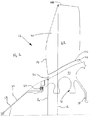
Fig. 2 is a partial axial cross-sectional view of an embodiment of the fan of the present disclosure. -
Fig. 1 illustrates a turbofangas turbine engine 10 generally comprising in serial flow communication, afan assembly 12 through which ambient air is propelled, and acore 13 including acompressor section 14 for pressurizing the air, acombustor 16 in which the compressed air is mixed with fuel and ignited for generating an annular stream of hot combustion gases, and aturbine section 18 for extracting energy from the combustion gases. A centerlinemain engine axis 13 extends longitudinally through theturbofan engine 10. - The
fan 12 propels air through both theengine core 13 and thebypass duct 22, and may be mounted to the low pressuremain engine shaft 11. Thefan 12 includes a plurality of radially extendingfan blades 20 and a central hub as will be seen, which hub has anose cone 22 mounted thereto to protect the hub. As will be described in greater detail below, thefan 12 is an integrally bladed rotor (IBR), wherein thefan blades 20 are integrally formed with the central hub that is fastened to the low pressure (LP)engine shaft 11 for rotation therewith. - Referring now to
Fig. 2 , the IBRfan 12 comprises a plurality offan blades 20 integrally formed with, and substantially radially extending from, acentral fan hub 36 which is mounted to an engine shaft, such as thelow pressure shaft 11, by means of one or more hub supportportions 38 which are also integrally formed with the hub. Each of theblades 20 defines anairfoil 28 which has a leadingedge 34 which extends from ablade root 30 to ablade tip 40. Theblade 20 is integrated with thehub 36, i.e. such theblades 20 are integrally formed as a monolithic component with thefan hub 36 to form an IBR fan. Thenose cone 22 of the engine may be fastened to an upstream end of thefan hub 36 by a plurality offasteners 29. - When the radius of the leading
edge 34 on thehub 36 is reduced while the radius of the blade tip at 40 is maintained, the flow area (FA) of thefan 20 is increased thus reducing the specific flow (SF). As seen inFig. 2 , the gaspath through thefan 12 is defined by the annular area between thehubs 30 and thetips 40 of thefan blades 20. The radius of the fan hub (RHUB), measured at the leadingedge 34 of theblade 20, defines the radially inner gaspath boundary and the radius of the blade tip (RTIP), also measured at the leadingedge 34, defines the radially outer gaspath boundary. The specific flow of thefan 12 is therefore defined as the mass flow (MF) of air entering the leading edge of thefan 12, divided by the flow area (FA) at the fan leading edge, normal to theengine axis 13. - The hub to tip ratio of the
IBR fan 12 is defined as the ratio of the radius of the fan hub (RHUB) at the leading edge divided by the radius of fan blade tip (RTIP) at the leading edge. As shown inFig. 2 , these radii are is measured from theengine centerline axis 13. - Thus, specific flow is determined as follows:

where SF is the specific flow, MF is the mass flow, and FA the flow area. Reduction of this SF of the fan is desirable as a reduced SF helps to improve the overall aerodynamic efficiency of the fan because of the lower air velocity. - A reduction in the hub to tip ratio (RHUB/RTIP) will therefore also cause a reduction in the specific flow (SF) of the fan. Alternatively, the radius of both the
hub 36 and theblade tip 40 can be reduced while retaining the same specific flow SF. However, the ratio of the hub to tip radii is preferably reduced. Accordingly, thepresent IBR fan 12 has a ratio of the hub radius to the tip radius, i.e. RHUB/RTIP, which is at least less than 0.29. In a particular embodiment, the ratio of the hub radius to the tip radius (RHUB/RTIP) is between about 0.25 and about 0.29. In a further particular embodiment, the ratio of the hub radius to the tip radius (RHUB/RTIP) is less than or equal to 0.25. - The advantage of a lower tip radius is a smaller diameter fan and therefore a lighter weight engine. Lowering the hub leading edge radius also changes the flow angle of the airstream, and the resulting rearward sweep in the lower portion of the
fan blade airfoils 28 improves performance by reducing the leading edge velocities through the sweep effect and also draws flow towards thehub 36 which helps to reduce flow separation that the blade root. - The advantage of using the integrally bladed rotor (IBR)
fan 12 is its reduced weight compared to a traditional detachable bladed rotor. The machining of anIBR fan 12 with such a low hub/tip ratio is made difficult by the lack of space between theblades 20, particularly at theblade roots 30 since the gap between the blades is much narrower the smaller the radius of the fan. - However, in one particular method of manufacturing the
IBR fan 12 described herein, it has been found that by first machining aroot stub 44 on thehub 36, the lower hub radius, and more particularly the low hub to tip radius ratios described above, can be obtained because it is easier to access the radial gap betweenadjacent blades 20 with machine tools. Theblade airfoils 28 may then be fixed to theroot stubs 44 be welded by Linear Friction Welding (LFW), for example, along thejoint line 42 as shown on theblade 20 inFig. 2 . It has been contemplated that alternative methods may also be used, such as forming aroot stub 44 only for every alternate blade, while machining thefull blade 20 between each alternate root stub. This would allow sufficient access for machine tools between two alternate full blades, to machine around the around the remaining root stub. - Thus, a low-
weight fan 12 as described herein is achieve, because of its integrated bladed rotor construction, and which provides a hub to tip radius ratio of at least less than 0.29, and more particularly between 0.25 and 0.29, and more particularly still a hub to tip radius ratio of 0.25 or less. - The above description is meant to be exemplary only, and one skilled in the art will recognize that changes may be made to the embodiments described while still falling within the scope of the appended claims, which define the present invention. Such modifications will be apparent to those skilled in the art, in light of a review of this disclosure.
Claims (13)
- A fan (12) for a turbofan gas turbine engine (10), the fan (12) comprising a rotor hub (36) and a plurality of radially extending fan blades (20) integral with the hub (36) to form an integrally bladed rotor (IBR), each fan blade (20) having a leading edge (34), a hub radius (RHUB) which is the radius of the leading edge (34) at the hub (36) relative to a centerline of the fan (12), and a tip radius (RTIP) which is the radius of the leading edge at a tip (40) of the fan blade (20) relative to the centerline of the fan (12), and wherein the ratio of the hub radius to the tip radius (RHUB/RTIP) is at least less than 0.29.
- The fan (12) as defined in claim 1, wherein the ratio of the hub radius to the tip radius (RHUB/RTIP) is less than or equal to 0.25.
- The fan (12) as defined in claim 1, wherein the ratio of the hub radius to the tip radius (RHUB/RTIP) is between 0.25 and 0.29.
- A fan preform for a fan (12) as defined in any preceding claim, wherein the fan preform includes root stubs (44) disposed on the hub (36) at positions corresponding to at least alternate ones of said fan blades (20), the root stubs (44) being first formed on the hub (36) prior to blades (20) being fastened thereto.
- The fan preform as defined in claim 4 wherein the root stubs (44) formed on the preform have airfoils (28) welded thereto to provide the integrally bladed rotor (IBR).
- The fan preform as defined in claim 4 or 5 wherein the airfoils (28) are linear-friction-welded to the respective root stubs (44).
- The fan preform as defined in any of claims 4 to 6 wherein all of the fan blades (20) are first formed as root stubs (44) on the hub (36).
- A method of manufacturing an integrally bladed rotor fan (12) for a turbofan gas turbine engine (10), comprising: forming a rotor hub preform defining a hub radius and having at least a number of root stubs (44) radially spaced apart on a periphery of the rotor hub preform; providing blade airfoils (28) having a length such that a ratio of the hub radius to a tip radius of the blade airfoils (28), once mounted to the hub (36), is at least less than 0.29; and subsequently fastening the blade airfoils (28) to the root stubs (44) to form fan blades (20) integrally formed with the hub (36) resulting in an integrally bladed rotor fan (12) having a hub to tip radius ratio (RHUB/RTIP) of at least less than 0.29.
- The method as defined in claim 8, wherein the step of selecting further comprises selecting the length of the blade airfoils (28) to define a ratio of the hub radius (RHUB) to the tip radius (RTIP) of the blade airfoils (28) that is between 0.25 and 0.29.
- The method as defined in claim 8, wherein the step of selecting further comprises selecting the length of the blade airfoils (28) to define a ratio of the hub radius (RHUB) to the tip radius (RTIP) of the blade airfoils (28) that is less than or equal to 0.25.
- The method as defined in any of claims 8, 9 or 10, wherein circumferentially alternate ones of said fan blades (20) are formed integrally with the hub preform without root stubs (44), leaving alternate root stubs (44) on the hub preform to provide access for machine tools between the circumferentially alternate ones of said fan blades (20).
- The method as defined in any of claims 8 to 11, wherein the step of fastening further comprises welding the blade airfoils (28) to the root stubs using Linear Friction Welding.
- A turbofan gas turbine engine (10) comprising a fan (12) upstream of at least one compressor (14), the fan (12) being a fan as defined in any of claims 1 to 3.
Applications Claiming Priority (1)
| Application Number | Priority Date | Filing Date | Title |
|---|---|---|---|
| US13/687,540 US9303589B2 (en) | 2012-11-28 | 2012-11-28 | Low hub-to-tip ratio fan for a turbofan gas turbine engine |
Publications (3)
| Publication Number | Publication Date |
|---|---|
| EP2738392A2 true EP2738392A2 (en) | 2014-06-04 |
| EP2738392A3 EP2738392A3 (en) | 2014-12-24 |
| EP2738392B1 EP2738392B1 (en) | 2019-01-02 |
Family
ID=49752949
Family Applications (1)
| Application Number | Title | Priority Date | Filing Date |
|---|---|---|---|
| EP13194497.7A Active EP2738392B1 (en) | 2012-11-28 | 2013-11-26 | Fan blade for a turbofan gas turbine engine |
Country Status (3)
| Country | Link |
|---|---|
| US (3) | US9303589B2 (en) |
| EP (1) | EP2738392B1 (en) |
| CA (2) | CA3142741A1 (en) |
Cited By (2)
| Publication number | Priority date | Publication date | Assignee | Title |
|---|---|---|---|---|
| FR3028574A1 (en) * | 2014-11-17 | 2016-05-20 | Snecma | MONOBLOC TANK DISK FOR A TURBOMACHINE BLOWER COMPRISING A UPSTREAM AND / OR DOWNWARD RECOVERY CONFERRING GREATER FLEXIBILITY TO ITS AUBES |
| US10408223B2 (en) | 2012-11-28 | 2019-09-10 | Pratt & Whitney Canada Corp. | Low hub-to-tip ratio fan for a turbofan gas turbine engine |
Families Citing this family (26)
| Publication number | Priority date | Publication date | Assignee | Title |
|---|---|---|---|---|
| US10287917B2 (en) * | 2013-05-09 | 2019-05-14 | United Technologies Corporation | Turbofan engine front section |
| DE102013213517A1 (en) * | 2013-07-10 | 2015-01-15 | Rolls-Royce Deutschland Ltd & Co Kg | Aircraft engine |
| FR3014150B1 (en) * | 2013-11-29 | 2018-03-02 | Safran Aircraft Engines | BLOWER, ESPECIALLY FOR A TURBOMACHINE |
| FR3014151B1 (en) * | 2013-11-29 | 2015-12-04 | Snecma | BLOWER, ESPECIALLY FOR A TURBOMACHINE |
| FR3046439B1 (en) * | 2016-01-05 | 2019-01-25 | Safran Aircraft Engines | VARIABLE TIMING BLOWER WITH LOW NO TURBOREACTOR |
| EP3238868A1 (en) * | 2016-04-27 | 2017-11-01 | MTU Aero Engines GmbH | Method for producing a rotor blade for a fluid flow engine |
| US10294965B2 (en) * | 2016-05-25 | 2019-05-21 | Honeywell International Inc. | Compression system for a turbine engine |
| GB2553146A (en) * | 2016-08-26 | 2018-02-28 | Rolls Royce Plc | A friction welding process |
| DE102016224386A1 (en) * | 2016-12-07 | 2018-06-07 | MTU Aero Engines AG | METHOD FOR PRODUCING A SHOVEL FOR A FLOW MACHINE |
| US11053797B2 (en) | 2017-01-23 | 2021-07-06 | General Electric Company | Rotor thrust balanced turbine engine |
| GB201702380D0 (en) * | 2017-02-14 | 2017-03-29 | Rolls Royce Plc | Gas turbine engine fan blade with axial lean |
| GB201702382D0 (en) | 2017-02-14 | 2017-03-29 | Rolls Royce Plc | Gas turbine engine fan blade |
| GB201702384D0 (en) | 2017-02-14 | 2017-03-29 | Rolls Royce Plc | Gas turbine engine fan blade |
| GB201702383D0 (en) * | 2017-02-14 | 2017-03-29 | Rolls Royce Plc | Gas turbine engine fan blade with axial lean |
| US11421627B2 (en) | 2017-02-22 | 2022-08-23 | General Electric Company | Aircraft and direct drive engine under wing installation |
| US10654577B2 (en) | 2017-02-22 | 2020-05-19 | General Electric Company | Rainbow flowpath low pressure turbine rotor assembly |
| US10670037B2 (en) * | 2017-11-21 | 2020-06-02 | General Electric Company | Turbofan engine's fan blade and setting method thereof |
| US11231043B2 (en) | 2018-02-21 | 2022-01-25 | General Electric Company | Gas turbine engine with ultra high pressure compressor |
| CN108302064A (en) * | 2018-03-15 | 2018-07-20 | 上海优睿农牧科技有限公司 | A kind of novel hub |
| US10823191B2 (en) | 2018-03-15 | 2020-11-03 | General Electric Company | Gas turbine engine arrangement with ultra high pressure compressor |
| GB201820919D0 (en) * | 2018-12-21 | 2019-02-06 | Rolls Royce Plc | Turbine engine |
| US11428160B2 (en) | 2020-12-31 | 2022-08-30 | General Electric Company | Gas turbine engine with interdigitated turbine and gear assembly |
| US11492918B1 (en) * | 2021-09-03 | 2022-11-08 | General Electric Company | Gas turbine engine with third stream |
| DE112022003963T5 (en) * | 2021-10-11 | 2024-07-04 | Milwaukee Electric Tool Corporation | BLOWER FOR A HANDHELD BLOWER |
| GB2617597B (en) * | 2022-04-13 | 2025-04-02 | Greenjets Ltd | Electric propulsion systems |
| US12416263B2 (en) | 2023-05-01 | 2025-09-16 | General Electric Company | Rotatable heat exchanger for a gas turbine engine |
Family Cites Families (34)
| Publication number | Priority date | Publication date | Assignee | Title |
|---|---|---|---|---|
| US3540682A (en) * | 1964-12-02 | 1970-11-17 | Gen Electric | Turbofan type engine frame and support system |
| US3494129A (en) * | 1968-03-06 | 1970-02-10 | Gen Electric | Fluid compressors and turbofan engines employing same |
| FR2248732A5 (en) | 1973-10-23 | 1975-05-16 | Onera (Off Nat Aerospatiale) | |
| US4595340A (en) | 1984-07-30 | 1986-06-17 | General Electric Company | Gas turbine bladed disk assembly |
| US4790133A (en) * | 1986-08-29 | 1988-12-13 | General Electric Company | High bypass ratio counterrotating turbofan engine |
| US5188275A (en) | 1990-05-24 | 1993-02-23 | Rolls-Royce Plc | Friction bonding clamp for a rotor blade |
| US5108261A (en) | 1991-07-11 | 1992-04-28 | United Technologies Corporation | Compressor disk assembly |
| US5169288A (en) * | 1991-09-06 | 1992-12-08 | General Electric Company | Low noise fan assembly |
| US5501575A (en) | 1995-03-01 | 1996-03-26 | United Technologies Corporation | Fan blade attachment for gas turbine engine |
| US5813593A (en) | 1996-11-15 | 1998-09-29 | General Electric Company | Translational friction welding apparatus and method |
| GB9713395D0 (en) | 1997-06-25 | 1997-08-27 | Rolls Royce Plc | Improvements in or relating to the friction welding of components |
| US6409469B1 (en) * | 2000-11-21 | 2002-06-25 | Pratt & Whitney Canada Corp. | Fan-stator interaction tone reduction |
| GB2382382B (en) | 2001-11-23 | 2005-08-10 | Rolls Royce Plc | A fan for a turbofan gas turbine engine |
| US6732502B2 (en) | 2002-03-01 | 2004-05-11 | General Electric Company | Counter rotating aircraft gas turbine engine with high overall pressure ratio compressor |
| DE102004042739A1 (en) * | 2004-09-03 | 2006-03-09 | Mtu Aero Engines Gmbh | Fan for an aircraft engine and aircraft engine |
| WO2006080055A1 (en) | 2005-01-26 | 2006-08-03 | Ishikawajima-Harima Heavy Industries Co., Ltd. | Turbofan engine |
| JP4911286B2 (en) | 2006-03-14 | 2012-04-04 | 株式会社Ihi | Fan dovetail structure |
| US7721526B2 (en) | 2006-06-28 | 2010-05-25 | Ishikawajima-Harima Heavy Industries Co., Ltd. | Turbofan engine |
| JP4911344B2 (en) * | 2006-07-04 | 2012-04-04 | 株式会社Ihi | Turbofan engine |
| WO2008117413A1 (en) | 2007-03-27 | 2008-10-02 | Ihi Corporation | Fan rotor blade support structure and turbofan engine having the same |
| EP2361350A1 (en) * | 2008-08-19 | 2011-08-31 | Sonic Blue Aerospace, Inc. | Magnetic advanced generation jet electric turbine |
| US9303589B2 (en) | 2012-11-28 | 2016-04-05 | Pratt & Whitney Canada Corp. | Low hub-to-tip ratio fan for a turbofan gas turbine engine |
| US10190496B2 (en) | 2013-03-15 | 2019-01-29 | United Technologies Corporation | Turbofan engine bearing and gearbox arrangement |
| WO2015050619A2 (en) | 2013-08-20 | 2015-04-09 | United Technologies Corporation | High thrust geared gas turbine engine |
| FR3014150B1 (en) | 2013-11-29 | 2018-03-02 | Safran Aircraft Engines | BLOWER, ESPECIALLY FOR A TURBOMACHINE |
| FR3014151B1 (en) | 2013-11-29 | 2015-12-04 | Snecma | BLOWER, ESPECIALLY FOR A TURBOMACHINE |
| US10072510B2 (en) | 2014-11-21 | 2018-09-11 | General Electric Company | Variable pitch fan for gas turbine engine and method of assembling the same |
| EP3067566B1 (en) | 2015-03-12 | 2018-08-22 | Rolls-Royce Corporation | Multi-stage co-rotating variable pitch fan |
| US10724541B2 (en) | 2015-12-31 | 2020-07-28 | United Technologies Corporation | Nacelle short inlet |
| GB201702384D0 (en) | 2017-02-14 | 2017-03-29 | Rolls Royce Plc | Gas turbine engine fan blade |
| GB201702380D0 (en) | 2017-02-14 | 2017-03-29 | Rolls Royce Plc | Gas turbine engine fan blade with axial lean |
| US10137981B2 (en) | 2017-03-31 | 2018-11-27 | General Electric Company | Electric propulsion system for an aircraft |
| GB201712993D0 (en) | 2017-08-14 | 2017-09-27 | Rolls Royce Plc | Gas turbine engine |
| GB2566045B (en) | 2017-08-31 | 2019-12-11 | Rolls Royce Plc | Gas turbine engine |
-
2012
- 2012-11-28 US US13/687,540 patent/US9303589B2/en active Active
-
2013
- 2013-11-18 CA CA3142741A patent/CA3142741A1/en active Pending
- 2013-11-18 CA CA2833986A patent/CA2833986C/en active Active
- 2013-11-26 EP EP13194497.7A patent/EP2738392B1/en active Active
-
2016
- 2016-02-24 US US15/052,178 patent/US9709070B2/en active Active
-
2017
- 2017-06-07 US US15/616,302 patent/US10408223B2/en active Active
Cited By (3)
| Publication number | Priority date | Publication date | Assignee | Title |
|---|---|---|---|---|
| US10408223B2 (en) | 2012-11-28 | 2019-09-10 | Pratt & Whitney Canada Corp. | Low hub-to-tip ratio fan for a turbofan gas turbine engine |
| FR3028574A1 (en) * | 2014-11-17 | 2016-05-20 | Snecma | MONOBLOC TANK DISK FOR A TURBOMACHINE BLOWER COMPRISING A UPSTREAM AND / OR DOWNWARD RECOVERY CONFERRING GREATER FLEXIBILITY TO ITS AUBES |
| US9863252B2 (en) | 2014-11-17 | 2018-01-09 | Snecma | Single-piece blisk for turbomachine fan comprising an upstream and/or downstream recess making its blades more flexible |
Also Published As
| Publication number | Publication date |
|---|---|
| US9709070B2 (en) | 2017-07-18 |
| US20140356159A1 (en) | 2014-12-04 |
| CA2833986C (en) | 2022-02-08 |
| EP2738392B1 (en) | 2019-01-02 |
| US9303589B2 (en) | 2016-04-05 |
| EP2738392A3 (en) | 2014-12-24 |
| CA3142741A1 (en) | 2014-05-28 |
| US20160238022A1 (en) | 2016-08-18 |
| US10408223B2 (en) | 2019-09-10 |
| US20170268529A1 (en) | 2017-09-21 |
| CA2833986A1 (en) | 2014-05-28 |
Similar Documents
| Publication | Publication Date | Title |
|---|---|---|
| EP2738392B1 (en) | Fan blade for a turbofan gas turbine engine | |
| EP3450727B1 (en) | Gas turbine engine | |
| EP3450726B1 (en) | Gas turbine engine | |
| EP3187712B1 (en) | Nacelle short inlet | |
| EP2543867B1 (en) | Efficient, low pressure ratio propulsor for gas turbine engines | |
| CA2893743C (en) | Airfoil with stepped spanwise thickness distribution | |
| EP3514334B1 (en) | Lightweight fan blade with mid-span shroud | |
| EP3450681B1 (en) | Gas turbine engine | |
| CN106050314B (en) | Turbine frame and airfoil for turbine frame | |
| US9932834B2 (en) | Rotor blade with a conic spline fillet at an intersection between a platform and a neck | |
| US9828864B2 (en) | Fan blade tall dovetail for individually bladed rotors | |
| US20170306768A1 (en) | Turbine engine shroud assembly | |
| EP2971550B1 (en) | Fan airfoil shrouds with area ruling in the shrouds | |
| US11274563B2 (en) | Turbine rear frame for a turbine engine | |
| US9970452B2 (en) | Forward-swept impellers and gas turbine engines employing the same | |
| EP3098383B1 (en) | Compressor airfoil with compound leading edge profile | |
| US9169730B2 (en) | Fan hub design | |
| EP3287601B1 (en) | Multi-piece non-linear fan blade | |
| US20180094638A1 (en) | Integrally bladed fan rotor | |
| CN120720263A (en) | Gas turbine core tie rod with reduced span |
Legal Events
| Date | Code | Title | Description |
|---|---|---|---|
| PUAI | Public reference made under article 153(3) epc to a published international application that has entered the european phase |
Free format text: ORIGINAL CODE: 0009012 |
|
| 17P | Request for examination filed |
Effective date: 20131126 |
|
| AK | Designated contracting states |
Kind code of ref document: A2 Designated state(s): AL AT BE BG CH CY CZ DE DK EE ES FI FR GB GR HR HU IE IS IT LI LT LU LV MC MK MT NL NO PL PT RO RS SE SI SK SM TR |
|
| AX | Request for extension of the european patent |
Extension state: BA ME |
|
| PUAL | Search report despatched |
Free format text: ORIGINAL CODE: 0009013 |
|
| AK | Designated contracting states |
Kind code of ref document: A3 Designated state(s): AL AT BE BG CH CY CZ DE DK EE ES FI FR GB GR HR HU IE IS IT LI LT LU LV MC MK MT NL NO PL PT RO RS SE SI SK SM TR |
|
| AX | Request for extension of the european patent |
Extension state: BA ME |
|
| RIC1 | Information provided on ipc code assigned before grant |
Ipc: F01D 5/34 20060101ALI20141117BHEP Ipc: F04D 29/02 20060101AFI20141117BHEP Ipc: B23K 20/12 20060101ALI20141117BHEP Ipc: F04D 29/32 20060101ALI20141117BHEP Ipc: F01D 5/30 20060101ALI20141117BHEP |
|
| R17P | Request for examination filed (corrected) |
Effective date: 20150624 |
|
| RBV | Designated contracting states (corrected) |
Designated state(s): AL AT BE BG CH CY CZ DE DK EE ES FI FR GB GR HR HU IE IS IT LI LT LU LV MC MK MT NL NO PL PT RO RS SE SI SK SM TR |
|
| GRAP | Despatch of communication of intention to grant a patent |
Free format text: ORIGINAL CODE: EPIDOSNIGR1 |
|
| STAA | Information on the status of an ep patent application or granted ep patent |
Free format text: STATUS: GRANT OF PATENT IS INTENDED |
|
| INTG | Intention to grant announced |
Effective date: 20180614 |
|
| GRAS | Grant fee paid |
Free format text: ORIGINAL CODE: EPIDOSNIGR3 |
|
| GRAA | (expected) grant |
Free format text: ORIGINAL CODE: 0009210 |
|
| STAA | Information on the status of an ep patent application or granted ep patent |
Free format text: STATUS: THE PATENT HAS BEEN GRANTED |
|
| AK | Designated contracting states |
Kind code of ref document: B1 Designated state(s): AL AT BE BG CH CY CZ DE DK EE ES FI FR GB GR HR HU IE IS IT LI LT LU LV MC MK MT NL NO PL PT RO RS SE SI SK SM TR |
|
| REG | Reference to a national code |
Ref country code: GB Ref legal event code: FG4D |
|
| REG | Reference to a national code |
Ref country code: CH Ref legal event code: EP Ref country code: AT Ref legal event code: REF Ref document number: 1084732 Country of ref document: AT Kind code of ref document: T Effective date: 20190115 |
|
| REG | Reference to a national code |
Ref country code: DE Ref legal event code: R096 Ref document number: 602013049114 Country of ref document: DE |
|
| REG | Reference to a national code |
Ref country code: IE Ref legal event code: FG4D |
|
| REG | Reference to a national code |
Ref country code: NL Ref legal event code: MP Effective date: 20190102 |
|
| REG | Reference to a national code |
Ref country code: LT Ref legal event code: MG4D |
|
| REG | Reference to a national code |
Ref country code: AT Ref legal event code: MK05 Ref document number: 1084732 Country of ref document: AT Kind code of ref document: T Effective date: 20190102 |
|
| PG25 | Lapsed in a contracting state [announced via postgrant information from national office to epo] |
Ref country code: NL Free format text: LAPSE BECAUSE OF FAILURE TO SUBMIT A TRANSLATION OF THE DESCRIPTION OR TO PAY THE FEE WITHIN THE PRESCRIBED TIME-LIMIT Effective date: 20190102 |
|
| PG25 | Lapsed in a contracting state [announced via postgrant information from national office to epo] |
Ref country code: SE Free format text: LAPSE BECAUSE OF FAILURE TO SUBMIT A TRANSLATION OF THE DESCRIPTION OR TO PAY THE FEE WITHIN THE PRESCRIBED TIME-LIMIT Effective date: 20190102 Ref country code: PT Free format text: LAPSE BECAUSE OF FAILURE TO SUBMIT A TRANSLATION OF THE DESCRIPTION OR TO PAY THE FEE WITHIN THE PRESCRIBED TIME-LIMIT Effective date: 20190502 Ref country code: ES Free format text: LAPSE BECAUSE OF FAILURE TO SUBMIT A TRANSLATION OF THE DESCRIPTION OR TO PAY THE FEE WITHIN THE PRESCRIBED TIME-LIMIT Effective date: 20190102 Ref country code: LT Free format text: LAPSE BECAUSE OF FAILURE TO SUBMIT A TRANSLATION OF THE DESCRIPTION OR TO PAY THE FEE WITHIN THE PRESCRIBED TIME-LIMIT Effective date: 20190102 Ref country code: PL Free format text: LAPSE BECAUSE OF FAILURE TO SUBMIT A TRANSLATION OF THE DESCRIPTION OR TO PAY THE FEE WITHIN THE PRESCRIBED TIME-LIMIT Effective date: 20190102 Ref country code: NO Free format text: LAPSE BECAUSE OF FAILURE TO SUBMIT A TRANSLATION OF THE DESCRIPTION OR TO PAY THE FEE WITHIN THE PRESCRIBED TIME-LIMIT Effective date: 20190402 Ref country code: FI Free format text: LAPSE BECAUSE OF FAILURE TO SUBMIT A TRANSLATION OF THE DESCRIPTION OR TO PAY THE FEE WITHIN THE PRESCRIBED TIME-LIMIT Effective date: 20190102 |
|
| PG25 | Lapsed in a contracting state [announced via postgrant information from national office to epo] |
Ref country code: IS Free format text: LAPSE BECAUSE OF FAILURE TO SUBMIT A TRANSLATION OF THE DESCRIPTION OR TO PAY THE FEE WITHIN THE PRESCRIBED TIME-LIMIT Effective date: 20190502 Ref country code: BG Free format text: LAPSE BECAUSE OF FAILURE TO SUBMIT A TRANSLATION OF THE DESCRIPTION OR TO PAY THE FEE WITHIN THE PRESCRIBED TIME-LIMIT Effective date: 20190402 Ref country code: LV Free format text: LAPSE BECAUSE OF FAILURE TO SUBMIT A TRANSLATION OF THE DESCRIPTION OR TO PAY THE FEE WITHIN THE PRESCRIBED TIME-LIMIT Effective date: 20190102 Ref country code: RS Free format text: LAPSE BECAUSE OF FAILURE TO SUBMIT A TRANSLATION OF THE DESCRIPTION OR TO PAY THE FEE WITHIN THE PRESCRIBED TIME-LIMIT Effective date: 20190102 Ref country code: HR Free format text: LAPSE BECAUSE OF FAILURE TO SUBMIT A TRANSLATION OF THE DESCRIPTION OR TO PAY THE FEE WITHIN THE PRESCRIBED TIME-LIMIT Effective date: 20190102 Ref country code: GR Free format text: LAPSE BECAUSE OF FAILURE TO SUBMIT A TRANSLATION OF THE DESCRIPTION OR TO PAY THE FEE WITHIN THE PRESCRIBED TIME-LIMIT Effective date: 20190403 |
|
| REG | Reference to a national code |
Ref country code: DE Ref legal event code: R097 Ref document number: 602013049114 Country of ref document: DE |
|
| PG25 | Lapsed in a contracting state [announced via postgrant information from national office to epo] |
Ref country code: CZ Free format text: LAPSE BECAUSE OF FAILURE TO SUBMIT A TRANSLATION OF THE DESCRIPTION OR TO PAY THE FEE WITHIN THE PRESCRIBED TIME-LIMIT Effective date: 20190102 Ref country code: IT Free format text: LAPSE BECAUSE OF FAILURE TO SUBMIT A TRANSLATION OF THE DESCRIPTION OR TO PAY THE FEE WITHIN THE PRESCRIBED TIME-LIMIT Effective date: 20190102 Ref country code: AL Free format text: LAPSE BECAUSE OF FAILURE TO SUBMIT A TRANSLATION OF THE DESCRIPTION OR TO PAY THE FEE WITHIN THE PRESCRIBED TIME-LIMIT Effective date: 20190102 Ref country code: SK Free format text: LAPSE BECAUSE OF FAILURE TO SUBMIT A TRANSLATION OF THE DESCRIPTION OR TO PAY THE FEE WITHIN THE PRESCRIBED TIME-LIMIT Effective date: 20190102 Ref country code: DK Free format text: LAPSE BECAUSE OF FAILURE TO SUBMIT A TRANSLATION OF THE DESCRIPTION OR TO PAY THE FEE WITHIN THE PRESCRIBED TIME-LIMIT Effective date: 20190102 Ref country code: AT Free format text: LAPSE BECAUSE OF FAILURE TO SUBMIT A TRANSLATION OF THE DESCRIPTION OR TO PAY THE FEE WITHIN THE PRESCRIBED TIME-LIMIT Effective date: 20190102 Ref country code: EE Free format text: LAPSE BECAUSE OF FAILURE TO SUBMIT A TRANSLATION OF THE DESCRIPTION OR TO PAY THE FEE WITHIN THE PRESCRIBED TIME-LIMIT Effective date: 20190102 Ref country code: RO Free format text: LAPSE BECAUSE OF FAILURE TO SUBMIT A TRANSLATION OF THE DESCRIPTION OR TO PAY THE FEE WITHIN THE PRESCRIBED TIME-LIMIT Effective date: 20190102 |
|
| PLBE | No opposition filed within time limit |
Free format text: ORIGINAL CODE: 0009261 |
|
| STAA | Information on the status of an ep patent application or granted ep patent |
Free format text: STATUS: NO OPPOSITION FILED WITHIN TIME LIMIT |
|
| PG25 | Lapsed in a contracting state [announced via postgrant information from national office to epo] |
Ref country code: SM Free format text: LAPSE BECAUSE OF FAILURE TO SUBMIT A TRANSLATION OF THE DESCRIPTION OR TO PAY THE FEE WITHIN THE PRESCRIBED TIME-LIMIT Effective date: 20190102 |
|
| 26N | No opposition filed |
Effective date: 20191003 |
|
| PG25 | Lapsed in a contracting state [announced via postgrant information from national office to epo] |
Ref country code: SI Free format text: LAPSE BECAUSE OF FAILURE TO SUBMIT A TRANSLATION OF THE DESCRIPTION OR TO PAY THE FEE WITHIN THE PRESCRIBED TIME-LIMIT Effective date: 20190102 |
|
| PG25 | Lapsed in a contracting state [announced via postgrant information from national office to epo] |
Ref country code: TR Free format text: LAPSE BECAUSE OF FAILURE TO SUBMIT A TRANSLATION OF THE DESCRIPTION OR TO PAY THE FEE WITHIN THE PRESCRIBED TIME-LIMIT Effective date: 20190102 |
|
| REG | Reference to a national code |
Ref country code: CH Ref legal event code: PL |
|
| PG25 | Lapsed in a contracting state [announced via postgrant information from national office to epo] |
Ref country code: LI Free format text: LAPSE BECAUSE OF NON-PAYMENT OF DUE FEES Effective date: 20191130 Ref country code: MC Free format text: LAPSE BECAUSE OF FAILURE TO SUBMIT A TRANSLATION OF THE DESCRIPTION OR TO PAY THE FEE WITHIN THE PRESCRIBED TIME-LIMIT Effective date: 20190102 Ref country code: LU Free format text: LAPSE BECAUSE OF NON-PAYMENT OF DUE FEES Effective date: 20191126 Ref country code: CH Free format text: LAPSE BECAUSE OF NON-PAYMENT OF DUE FEES Effective date: 20191130 |
|
| REG | Reference to a national code |
Ref country code: BE Ref legal event code: MM Effective date: 20191130 |
|
| PG25 | Lapsed in a contracting state [announced via postgrant information from national office to epo] |
Ref country code: IE Free format text: LAPSE BECAUSE OF NON-PAYMENT OF DUE FEES Effective date: 20191126 |
|
| PG25 | Lapsed in a contracting state [announced via postgrant information from national office to epo] |
Ref country code: BE Free format text: LAPSE BECAUSE OF NON-PAYMENT OF DUE FEES Effective date: 20191130 |
|
| PG25 | Lapsed in a contracting state [announced via postgrant information from national office to epo] |
Ref country code: CY Free format text: LAPSE BECAUSE OF FAILURE TO SUBMIT A TRANSLATION OF THE DESCRIPTION OR TO PAY THE FEE WITHIN THE PRESCRIBED TIME-LIMIT Effective date: 20190102 |
|
| PG25 | Lapsed in a contracting state [announced via postgrant information from national office to epo] |
Ref country code: MT Free format text: LAPSE BECAUSE OF FAILURE TO SUBMIT A TRANSLATION OF THE DESCRIPTION OR TO PAY THE FEE WITHIN THE PRESCRIBED TIME-LIMIT Effective date: 20190102 Ref country code: HU Free format text: LAPSE BECAUSE OF FAILURE TO SUBMIT A TRANSLATION OF THE DESCRIPTION OR TO PAY THE FEE WITHIN THE PRESCRIBED TIME-LIMIT; INVALID AB INITIO Effective date: 20131126 |
|
| PG25 | Lapsed in a contracting state [announced via postgrant information from national office to epo] |
Ref country code: MK Free format text: LAPSE BECAUSE OF FAILURE TO SUBMIT A TRANSLATION OF THE DESCRIPTION OR TO PAY THE FEE WITHIN THE PRESCRIBED TIME-LIMIT Effective date: 20190102 |
|
| P01 | Opt-out of the competence of the unified patent court (upc) registered |
Effective date: 20230530 |
|
| PGFP | Annual fee paid to national office [announced via postgrant information from national office to epo] |
Ref country code: DE Payment date: 20251022 Year of fee payment: 13 |
|
| PGFP | Annual fee paid to national office [announced via postgrant information from national office to epo] |
Ref country code: GB Payment date: 20251022 Year of fee payment: 13 |
|
| PGFP | Annual fee paid to national office [announced via postgrant information from national office to epo] |
Ref country code: FR Payment date: 20251022 Year of fee payment: 13 |