EP2738358A1 - Turbomachine component including a seal member - Google Patents
Turbomachine component including a seal member Download PDFInfo
- Publication number
- EP2738358A1 EP2738358A1 EP13192885.5A EP13192885A EP2738358A1 EP 2738358 A1 EP2738358 A1 EP 2738358A1 EP 13192885 A EP13192885 A EP 13192885A EP 2738358 A1 EP2738358 A1 EP 2738358A1
- Authority
- EP
- European Patent Office
- Prior art keywords
- receiving passage
- sealing surface
- turbomachine
- seal
- seal receiving
- Prior art date
- Legal status (The legal status is an assumption and is not a legal conclusion. Google has not performed a legal analysis and makes no representation as to the accuracy of the status listed.)
- Withdrawn
Links
- 238000007789 sealing Methods 0.000 claims abstract description 57
- 239000007789 gas Substances 0.000 description 10
- 239000012530 fluid Substances 0.000 description 5
- 229910000831 Steel Inorganic materials 0.000 description 4
- 239000000919 ceramic Substances 0.000 description 4
- 239000000463 material Substances 0.000 description 4
- 239000010959 steel Substances 0.000 description 4
- 229910052751 metal Inorganic materials 0.000 description 3
- 239000002184 metal Substances 0.000 description 3
- CWYNVVGOOAEACU-UHFFFAOYSA-N Fe2+ Chemical compound [Fe+2] CWYNVVGOOAEACU-UHFFFAOYSA-N 0.000 description 2
- 239000000956 alloy Substances 0.000 description 2
- 229910045601 alloy Inorganic materials 0.000 description 2
- 239000002131 composite material Substances 0.000 description 2
- -1 ferrous metals Chemical class 0.000 description 2
- 238000004519 manufacturing process Methods 0.000 description 2
- 239000000203 mixture Substances 0.000 description 2
- 230000007704 transition Effects 0.000 description 2
- 230000004075 alteration Effects 0.000 description 1
- 238000002485 combustion reaction Methods 0.000 description 1
- 230000008602 contraction Effects 0.000 description 1
- 238000001816 cooling Methods 0.000 description 1
- 239000000446 fuel Substances 0.000 description 1
- 238000006467 substitution reaction Methods 0.000 description 1
Images


Classifications
-
- F—MECHANICAL ENGINEERING; LIGHTING; HEATING; WEAPONS; BLASTING
- F02—COMBUSTION ENGINES; HOT-GAS OR COMBUSTION-PRODUCT ENGINE PLANTS
- F02C—GAS-TURBINE PLANTS; AIR INTAKES FOR JET-PROPULSION PLANTS; CONTROLLING FUEL SUPPLY IN AIR-BREATHING JET-PROPULSION PLANTS
- F02C7/00—Features, components parts, details or accessories, not provided for in, or of interest apart form groups F02C1/00 - F02C6/00; Air intakes for jet-propulsion plants
-
- F—MECHANICAL ENGINEERING; LIGHTING; HEATING; WEAPONS; BLASTING
- F01—MACHINES OR ENGINES IN GENERAL; ENGINE PLANTS IN GENERAL; STEAM ENGINES
- F01D—NON-POSITIVE DISPLACEMENT MACHINES OR ENGINES, e.g. STEAM TURBINES
- F01D11/00—Preventing or minimising internal leakage of working-fluid, e.g. between stages
- F01D11/005—Sealing means between non relatively rotating elements
-
- F—MECHANICAL ENGINEERING; LIGHTING; HEATING; WEAPONS; BLASTING
- F16—ENGINEERING ELEMENTS AND UNITS; GENERAL MEASURES FOR PRODUCING AND MAINTAINING EFFECTIVE FUNCTIONING OF MACHINES OR INSTALLATIONS; THERMAL INSULATION IN GENERAL
- F16J—PISTONS; CYLINDERS; SEALINGS
- F16J15/00—Sealings
- F16J15/16—Sealings between relatively-moving surfaces
- F16J15/32—Sealings between relatively-moving surfaces with elastic sealings, e.g. O-rings
- F16J15/3284—Sealings between relatively-moving surfaces with elastic sealings, e.g. O-rings characterised by their structure; Selection of materials
- F16J15/3288—Filamentary structures, e.g. brush seals
-
- F—MECHANICAL ENGINEERING; LIGHTING; HEATING; WEAPONS; BLASTING
- F05—INDEXING SCHEMES RELATING TO ENGINES OR PUMPS IN VARIOUS SUBCLASSES OF CLASSES F01-F04
- F05D—INDEXING SCHEME FOR ASPECTS RELATING TO NON-POSITIVE-DISPLACEMENT MACHINES OR ENGINES, GAS-TURBINES OR JET-PROPULSION PLANTS
- F05D2240/00—Components
- F05D2240/55—Seals
- F05D2240/56—Brush seals
-
- F—MECHANICAL ENGINEERING; LIGHTING; HEATING; WEAPONS; BLASTING
- F23—COMBUSTION APPARATUS; COMBUSTION PROCESSES
- F23R—GENERATING COMBUSTION PRODUCTS OF HIGH PRESSURE OR HIGH VELOCITY, e.g. GAS-TURBINE COMBUSTION CHAMBERS
- F23R2900/00—Special features of, or arrangements for continuous combustion chambers; Combustion processes therefor
- F23R2900/00012—Details of sealing devices
Definitions
- the subject matter disclosed herein relates generally to the art of turbomachines and, more particularly, to a seal member for a turbomachine component.
- turbomachines include a compressor portion linked to a turbine portion through a common compressor/turbine shaft or rotor and a combustor assembly.
- the compressor portion guides a compressed air flow through a number of sequential stages toward the combustor assembly.
- the compressed air flow mixes with a fuel to form a combustible mixture.
- the combustible mixture is combusted in the combustor assembly to form hot gases.
- the hot gases are guided to the turbine portion through a transition piece.
- the hot gases expand through the turbine portion rotating turbine blades to create work that is output, for example, to power a generator, a pump, or to provide power to a vehicle.
- a portion of the compressed airflow is passed through the turbine portion for cooling purposes.
- the turbine blades are arranged in a housing including first and second housing halves joined along a horizontal joint.
- Other turbomachine components such as the compressor portion, may also include horizontal joints.
- several turbomachine components, such as the combustor assembly include first and second housing halves joined along an axial joint. Regardless of the orientation, a seal is provided between the housing halves to limit leakage of turbomachine fluids.
- the seal is formed from a flexible metal that accommodates thermal expansion and contraction of the first and second housing halves resulting from temperature differences that arise during operation of the turbomachine.
- a turbomachine component includes a first housing portion having a first end that extends to a second end. At least one of the first and second ends includes a first sealing surface having a seal receiving passage.
- a second housing portion includes a first end that extends to a second end. At least one of the first and second ends includes a second sealing surface configured and disposed to register with the first sealing surface.
- a seal member is provided in the seal receiving passage. The seal member includes a plurality of bristles that extend toward the other of the first and second seal receiving passages.
- a turbomachine includes a compressor portion, a turbine portion fluidically connected, and mechanically linked, to the compressor portion, and a combustor assembly fluidically connected to the compressor portion and the turbine portion.
- At least one of the compressor portion, the turbine portion, and the combustor assembly includes a first housing portion having a first end that extends to a second end. At least one of the first and second ends includes a first sealing surface having a seal receiving passage.
- the at least one of the compressor portion, the turbine portion, and the combustor assembly also includes a second housing portion having a first end that extends to a second end. At least one of the first and second ends includes a second sealing surface configured and disposed to register with the first sealing surface.
- a seal member is provided in the seal receiving passage.
- the seal member includes a plurality of bristles that extend toward the other of the first and second seal receiving passages.
- Gas turbomachine 2 in accordance with an exemplary embodiment is indicated generally at 2 in FIG. 1 .
- Gas turbomachine 2 includes a compressor portion 4 operatively connected to a turbine portion 6.
- a combustor assembly 8 is fluidically connected to compressor portion 4 and turbine portion 6.
- Combustor assembly 8 includes a plurality of combustors, one of which is indicated at 10, arranged in a can-annular array. Of course it should be understood that the number and arrangement of combustors 10 may vary.
- Combustor assembly 8 is fluidically connected to turbine portion 6 through a transition piece (not shown).
- Compressor portion 4 includes a plurality of compressor stages (not shown) housed within a compressor casing 14 and turbine portion 6 includes a plurality of turbine stages (also not shown) housed within a turbine casing 16.
- Compressor casing 14 includes a forward compressor end section 18 that extends to an aft compressor end section 19 along a substantially longitudinal axis.
- Compressor casing 14 also includes a first compressor housing portion 20 and a second compressor housing portion 21.
- First compressor housing portion 20 is joined to second compressor housing portion 21 through a substantially horizontal joint 24.
- turbine casing 16 includes a forward turbine end section 28 that extends to an aft turbine end section 29 along the longitudinal axis.
- Turbine casing 16 also includes a first turbine housing portion 31 and a second turbine housing portion 32.
- First turbine housing portion 31 is joined to second turbine housing portion 32 along a substantially horizontal joint 34.
- combustor 10 includes a first combustor housing portion 39 joined to a second combustor housing portion 40 through a generally annular joint 42.
- First compressor housing portion 20 includes a first end 57 that extends to a second end 59.
- First end 57 includes a sealing surface 63 that extends along the longitudinal axis between forward compressor end section 18 and aft compressor end section 19. Sealing surface 63 includes a first seal receiving passage 66.
- Second end 59 includes a similar sealing surface (not shown).
- Second compressor housing portion 21 includes a first end 70 that extends to a second end 72.
- First end 70 includes a sealing surface 76 that extends along the longitudinal axis between forward compressor end section 18 and aft compressor end section 19. Sealing surface 76 includes a second seal receiving passage 80.
- a seal member 90 extends between first seal receiving passage 66 and second seal receiving passage 80 along horizontal joint 24. More specifically, seal member 90 includes a flange 93 mounted in second seal receiving passage 80. As best shown in FIG. 3 , flange 93 supports a plurality of bristles 96 that extend into first seal receiving passage 66. Bristles 96 are densely packed to reduce any escape of fluids from compressor portion 4 through horizontal joint 24. In accordance with an aspect of the exemplary embodiment, bristles 96 are formed from ferrous, e.g., steel and/or alloys of steel. Of course other materials such as ceramics, ceramic composites, and non-ferrous metals may also be employed in the fabrication of bristles 96.
- Bristles 96 are relatively flexible so as to accommodate any differences in thermal expansion between first compressor housing portion 20 and second compressor housing portion 21 resulting from operation of gas turbomachine 2. At this point it should be understood that while described as sealing between two compressor housing halves, seal member 90 may also be employed to seal between any number of housing portions that combine to form compressor casing 14, turbine casing 16, and/or an exhaust assembly (not separately labeled).
- first combustor housing portion 39 includes a first end section 110 having a generally annular opening (not separately labeled) that extends to a second end section 112.
- Second end section 112 includes a generally annular opening (also not separately labeled) that is configured to receive first end section 110.
- Second end section 112 includes a sealing surface 115 having a seal receiving passage 119.
- Seal receiving passage 119 includes a recess portion 124 that forms a keyway 125.
- Second combustor housing portion 40 includes a first end section 130 that extends to a second end section 133.
- First end section 130 includes a recess (not separately labeled) that defines, at least in part, a sealing surface 136. With this arrangement, second end section 112 of first combustor housing portion 39 is received within first end section 130 of second combustor housing portion 40. A seal member 150 is arranged at a generally annular joint 42 to limit escape of gases from combustor 10.
- seal member 150 extends between seal receiving passage 119 and sealing surface 136 and extends about generally annular joint 42. More specifically, seal member 150 includes a flange 152 mounted in seal receiving passage 119. Flange 152 includes an arcuate profile that generally corresponds to a geometry of second end section 112. In addition, flange 152 includes a mounting element 154 that takes the form of a key 155 configured to extend into, and matingly engage with, recess portion 124. Flange 152 supports a plurality of bristles 156 that extend toward and abut sealing surface 136. Bristles 156 are densely packed to reduce any escape of fluids from combustor 10 through generally annular joint 42.
- bristles 156 are formed from ferrous, e.g., steel and/or alloys of steel. Of course other materials such as ceramics, ceramic composites, and non-ferrous metals may also be employed in the fabrication of bristles 156. Bristles 156 are relatively flexible so as to accommodate any differences in thermal expansion between first combustor housing portion 39 and second combustor housing portion 40 resulting from operation of gas turbomachine 2. While shown as being employed as an axial seal, seal member 150 may also be configured as a radial seal. When configured as a radial seal, the seal member may include bristles that extend radially inwardly or bristles that extend radially outwardly depending on seal member orientation. In addition, it should be understood that the housing could represent inner and/or outer flanges an exhaust assembly and that the seal member may also be employed to seal between the inner and/or outer flanges.
- the exemplary embodiments describe a seal member that includes bristles to limit flow of fluids through turbomachine joints.
- the seal member may be employed at joints having a generally liner geometry or joints having a generally curvilinear geometry.
- the seal member may be used between a variety of surfaces, including between housing portions of a turbine casing or joints in other turbomachine components to limit fluid leakage.
- the bristles may be formed from a variety of materials, the particular type of material chosen may be related to a particular application for the seal member.
Landscapes
- Engineering & Computer Science (AREA)
- General Engineering & Computer Science (AREA)
- Mechanical Engineering (AREA)
- Chemical & Material Sciences (AREA)
- Combustion & Propulsion (AREA)
- Turbine Rotor Nozzle Sealing (AREA)
Abstract
Description
- The subject matter disclosed herein relates generally to the art of turbomachines and, more particularly, to a seal member for a turbomachine component.
- Many turbomachines include a compressor portion linked to a turbine portion through a common compressor/turbine shaft or rotor and a combustor assembly. The compressor portion guides a compressed air flow through a number of sequential stages toward the combustor assembly. In the combustor assembly, the compressed air flow mixes with a fuel to form a combustible mixture. The combustible mixture is combusted in the combustor assembly to form hot gases. The hot gases are guided to the turbine portion through a transition piece. The hot gases expand through the turbine portion rotating turbine blades to create work that is output, for example, to power a generator, a pump, or to provide power to a vehicle. In addition to providing compressed air for combustion, a portion of the compressed airflow is passed through the turbine portion for cooling purposes.
- In many cases, the turbine blades are arranged in a housing including first and second housing halves joined along a horizontal joint. Other turbomachine components, such as the compressor portion, may also include horizontal joints. In addition to horizontal joints, several turbomachine components, such as the combustor assembly include first and second housing halves joined along an axial joint. Regardless of the orientation, a seal is provided between the housing halves to limit leakage of turbomachine fluids. Generally, the seal is formed from a flexible metal that accommodates thermal expansion and contraction of the first and second housing halves resulting from temperature differences that arise during operation of the turbomachine.
- According to one aspect of the present invention, a turbomachine component includes a first housing portion having a first end that extends to a second end. At least one of the first and second ends includes a first sealing surface having a seal receiving passage. A second housing portion includes a first end that extends to a second end. At least one of the first and second ends includes a second sealing surface configured and disposed to register with the first sealing surface. A seal member is provided in the seal receiving passage. The seal member includes a plurality of bristles that extend toward the other of the first and second seal receiving passages.
- According to another aspect of an exemplary embodiment, a turbomachine includes a compressor portion, a turbine portion fluidically connected, and mechanically linked, to the compressor portion, and a combustor assembly fluidically connected to the compressor portion and the turbine portion. At least one of the compressor portion, the turbine portion, and the combustor assembly includes a first housing portion having a first end that extends to a second end. At least one of the first and second ends includes a first sealing surface having a seal receiving passage. The at least one of the compressor portion, the turbine portion, and the combustor assembly also includes a second housing portion having a first end that extends to a second end. At least one of the first and second ends includes a second sealing surface configured and disposed to register with the first sealing surface. A seal member is provided in the seal receiving passage. The seal member includes a plurality of bristles that extend toward the other of the first and second seal receiving passages.
- Various advantages and features will become more apparent from the following description taken in conjunction with the drawings.
- The subject matter, which is regarded as the invention, is particularly pointed out and distinctly claimed in the claims at the conclusion of the specification. The foregoing and other features, and advantages of the invention are apparent from the following detailed description taken in conjunction with the accompanying drawings in which:
-
FIG. 1 is a perspective view of a gas turbomachine including turbomachine component having a seal member in accordance with an exemplary embodiment; -
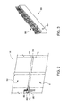
FIG. 2 is a partial perspective view of a compressor casing including first and second housing portions joined through a seal member in accordance with an exemplary embodiment; -
FIG. 3 is a partial perspective view of the seal member ofFIG. 2 ; -
FIG. 4 is a partial perspective view of a combustor of the gas turbomachine ofFIG. 1 including first and second housing portions joined through a seal member in accordance with another aspect of an exemplary embodiment; and -
FIG. 5 is a partial perspective view of the seal member ofFIG. 4 . - The detailed description explains embodiments of the invention, together with advantages and features, by way of example with reference to the drawings.
- A gas turbomachine in accordance with an exemplary embodiment is indicated generally at 2 in
FIG. 1 .Gas turbomachine 2 includes a compressor portion 4 operatively connected to aturbine portion 6. Acombustor assembly 8 is fluidically connected to compressor portion 4 andturbine portion 6.Combustor assembly 8 includes a plurality of combustors, one of which is indicated at 10, arranged in a can-annular array. Of course it should be understood that the number and arrangement ofcombustors 10 may vary.Combustor assembly 8 is fluidically connected toturbine portion 6 through a transition piece (not shown). Compressor portion 4 includes a plurality of compressor stages (not shown) housed within acompressor casing 14 andturbine portion 6 includes a plurality of turbine stages (also not shown) housed within aturbine casing 16. -
Compressor casing 14 includes a forwardcompressor end section 18 that extends to an aftcompressor end section 19 along a substantially longitudinal axis.Compressor casing 14 also includes a firstcompressor housing portion 20 and a secondcompressor housing portion 21. Firstcompressor housing portion 20 is joined to secondcompressor housing portion 21 through a substantiallyhorizontal joint 24. Similarly,turbine casing 16 includes a forwardturbine end section 28 that extends to an aftturbine end section 29 along the longitudinal axis.Turbine casing 16 also includes a firstturbine housing portion 31 and a secondturbine housing portion 32. Firstturbine housing portion 31 is joined to secondturbine housing portion 32 along a substantiallyhorizontal joint 34. Also illustrated inFIG. 1 ,combustor 10 includes a firstcombustor housing portion 39 joined to a secondcombustor housing portion 40 through a generallyannular joint 42. - Reference will now be made to
FIG. 2 in describing details ofcompressor casing 14 with an understanding thatturbine casing 16 may include similar structure. Firstcompressor housing portion 20 includes afirst end 57 that extends to asecond end 59.First end 57 includes asealing surface 63 that extends along the longitudinal axis between forwardcompressor end section 18 and aftcompressor end section 19.Sealing surface 63 includes a firstseal receiving passage 66.Second end 59 includes a similar sealing surface (not shown). Secondcompressor housing portion 21 includes afirst end 70 that extends to asecond end 72.First end 70 includes asealing surface 76 that extends along the longitudinal axis between forwardcompressor end section 18 and aftcompressor end section 19.Sealing surface 76 includes a secondseal receiving passage 80. - In accordance with an exemplary embodiment, a
seal member 90 extends between firstseal receiving passage 66 and secondseal receiving passage 80 alonghorizontal joint 24. More specifically,seal member 90 includes aflange 93 mounted in secondseal receiving passage 80. As best shown inFIG. 3 ,flange 93 supports a plurality ofbristles 96 that extend into firstseal receiving passage 66.Bristles 96 are densely packed to reduce any escape of fluids from compressor portion 4 throughhorizontal joint 24. In accordance with an aspect of the exemplary embodiment,bristles 96 are formed from ferrous, e.g., steel and/or alloys of steel. Of course other materials such as ceramics, ceramic composites, and non-ferrous metals may also be employed in the fabrication ofbristles 96.Bristles 96 are relatively flexible so as to accommodate any differences in thermal expansion between firstcompressor housing portion 20 and secondcompressor housing portion 21 resulting from operation ofgas turbomachine 2. At this point it should be understood that while described as sealing between two compressor housing halves,seal member 90 may also be employed to seal between any number of housing portions that combine to formcompressor casing 14,turbine casing 16, and/or an exhaust assembly (not separately labeled). - Reference will now follow to
FIG. 4 in describing generally annular joint 42. As shown, firstcombustor housing portion 39 includes afirst end section 110 having a generally annular opening (not separately labeled) that extends to asecond end section 112.Second end section 112 includes a generally annular opening (also not separately labeled) that is configured to receivefirst end section 110.Second end section 112 includes a sealingsurface 115 having aseal receiving passage 119.Seal receiving passage 119 includes arecess portion 124 that forms akeyway 125. Secondcombustor housing portion 40 includes afirst end section 130 that extends to asecond end section 133.First end section 130 includes a recess (not separately labeled) that defines, at least in part, a sealingsurface 136. With this arrangement,second end section 112 of firstcombustor housing portion 39 is received withinfirst end section 130 of secondcombustor housing portion 40. Aseal member 150 is arranged at a generally annular joint 42 to limit escape of gases fromcombustor 10. - As shown in
FIG. 5 ,seal member 150 extends betweenseal receiving passage 119 and sealingsurface 136 and extends about generally annular joint 42. More specifically,seal member 150 includes aflange 152 mounted inseal receiving passage 119.Flange 152 includes an arcuate profile that generally corresponds to a geometry ofsecond end section 112. In addition,flange 152 includes a mountingelement 154 that takes the form of a key 155 configured to extend into, and matingly engage with,recess portion 124.Flange 152 supports a plurality ofbristles 156 that extend toward andabut sealing surface 136.Bristles 156 are densely packed to reduce any escape of fluids fromcombustor 10 through generally annular joint 42. In a manner similar to that described above, bristles 156 are formed from ferrous, e.g., steel and/or alloys of steel. Of course other materials such as ceramics, ceramic composites, and non-ferrous metals may also be employed in the fabrication ofbristles 156.Bristles 156 are relatively flexible so as to accommodate any differences in thermal expansion between firstcombustor housing portion 39 and secondcombustor housing portion 40 resulting from operation ofgas turbomachine 2. While shown as being employed as an axial seal,seal member 150 may also be configured as a radial seal. When configured as a radial seal, the seal member may include bristles that extend radially inwardly or bristles that extend radially outwardly depending on seal member orientation. In addition, it should be understood that the housing could represent inner and/or outer flanges an exhaust assembly and that the seal member may also be employed to seal between the inner and/or outer flanges. - At this point it should be understood that the exemplary embodiments describe a seal member that includes bristles to limit flow of fluids through turbomachine joints. The seal member may be employed at joints having a generally liner geometry or joints having a generally curvilinear geometry. In addition while described as being employed between housing portions of a compressor casing and a combustor, the seal member may be used between a variety of surfaces, including between housing portions of a turbine casing or joints in other turbomachine components to limit fluid leakage. Finally, while the bristles may be formed from a variety of materials, the particular type of material chosen may be related to a particular application for the seal member.
- While the invention has been described in detail in connection with only a limited number of embodiments, it should be readily understood that the invention is not limited to such disclosed embodiments. Rather, the invention can be modified to incorporate any number of variations, alterations, substitutions or equivalent arrangements not heretofore described, but which are commensurate with the spirit and scope of the invention. Additionally, while various embodiments of the invention have been described, it is to be understood that aspects of the invention may include only some of the described embodiments. Accordingly, the invention is not to be seen as limited by the foregoing description, but is only limited by the scope of the appended claims.
- Various aspects and embodiments of the present invention are defined by the following numbered clauses:
- 1. A turbomachine component comprising:
- a first housing portion including a first end that extends to a second end, at least one of the first and second ends including a first sealing surface having a seal receiving passage;
- a second housing portion including a first end that extends to a second end, at least one of the first and second ends including a second sealing surface configured and disposed to register with the first sealing surface; and
- a seal member provided in the seal receiving passage, the seal member including a plurality of bristles that extend toward the second sealing surface.
- 2. The turbomachine component according to clause 1, wherein the seal member includes a flange that supports the plurality of bristles, the flange being received in the seal receiving passage.
- 3. The turbomachine component according to any preceding clause, wherein the flange includes a mounting element configured and disposed to be received in the seal receiving passage.
- 4. The turbomachine component according to any preceding clause, wherein the seal receiving passage includes a recess portion that extends into the one of the first and second sealing surfaces, the mounting element being configured and disposed to nest within the recess portion.
- 5. The turbomachine component according to any preceding clause, wherein the first housing portion includes a first end section that extends to a second end section along a generally longitudinal axis, the first and second sealing surfaces extending axially between the first and second end sections.
- 6. The turbomachine component according to any preceding clause, wherein the first and second housing portions form a compressor casing.
- 7. The turbomachine component according to any preceding clause, wherein the first and second sealing surfaces are configured and disposed to form a horizontal joint.
- 8. The turbomachine component according to any preceding clause, wherein the first sealing surface defines a first generally annular opening and the second sealing surface defines a second generally annular opening.
- 9. The turbomachine component of any preceding clause, wherein the first and second housing portions are joined to form a combustor casing.
- 10. The turbomachine component of any preceding clause, wherein the first and second sealing surfaces are configured and disposed to establish a generally annular joint.
- 11. The turbomachine component according to any preceding clause, wherein the second sealing surface includes another seal receiving passage, the seal member extending from the seal receiving passage into the another seal receiving passage.
- 12. A turbomachine comprising:
- a compressor portion;
- a turbine portion fluidically connected and mechanically linked to the compressor portion;
- a combustor assembly fluidically connected to the compressor portion and the turbine portion, at least one of the compressor portion, turbine portion, and combustor assembly comprising:
- a first housing portion including a first end that extends to a second end, at least one of the first and second ends including a first sealing surface having a seal receiving passage;
- a second housing portion including a first end that extends to a second end, at least one of the first and second ends including a second sealing surface configured and disposed to register with the first sealing surface; and
- a seal member provided in the first seal receiving passage, the seal member including a plurality of bristles that extend toward the second sealing surface.
- 13. The turbomachine according to any preceding clause, wherein the seal member includes a flange that supports the plurality of bristles, the flange being received in the seal receiving passage.
- 14. The turbomachine according to any preceding clause, wherein the flange includes a mounting element configured and disposed to be received in the seal receiving passage.
- 15. The turbomachine according to any preceding clause, wherein the seal receiving passage includes a recess portion that extends into the one of the first and second sealing surfaces, the mounting element being configured and disposed to nest within the recess portion.
- 16. The turbomachine according to any preceding clause, wherein the first housing portion includes a first end section that extends to a second end section along a generally longitudinal axis, the first and second sealing surfaces extending axially between the first and second end sections.
- 17. The turbomachine according to any preceding clause, wherein the first and second housing portions form a casing for the compressor portion.
- 18. The turbomachine according to any preceding clause, wherein the first and second sealing surfaces are configured and disposed to form a horizontal joint.
- 19. The turbomachine according to any preceding clause, wherein the first sealing surface defines a first generally annular opening and the second sealing surface defines a second generally annular opening.
- 20. The turbomachine according to any preceding clause, wherein the second sealing surface includes another seal receiving passage, the seal member extending from the seal receiving passage into the another seal receiving passage.
Claims (15)
- A turbomachine component comprising:a first housing portion (31) including a first end (57) that extends to a second end (59), at least one of the first and second ends (57, 59) including a first sealing surface (76) having a seal receiving passage (80);a second housing portion (32) including a first end (57) that extends to a second end (59), at least one of the first and second ends (57, 59) including a second sealing surface (76) configured and disposed to register with the first sealing surface (76); anda seal member (90) provided in the seal receiving passage (80), the seal member (90) including a plurality of bristles (96) that extend toward the second sealing surface (76).
- The turbomachine component according to claim 1, wherein the seal member (90) includes a flange (93) that supports the plurality of bristles (96), the flange being received in the seal receiving passage (80).
- The turbomachine component according to claim 2, wherein the flange (93) includes a mounting element (154) configured and disposed to be received in the seal receiving passage (80).
- The turbomachine component according to claim 3, wherein the seal receiving passage (80) includes a recess portion (124) that extends into the one of the first and second sealing surfaces, the mounting element (154) being configured and disposed to nest within the recess portion (124).
- The turbomachine component according to any preceding claim, wherein the first housing portion (31) includes a first end section that extends to a second end section along a generally longitudinal axis, the first and second sealing surfaces (76) extending axially between the first and second end sections.
- The turbomachine component according to any preceding claim, wherein the first and second housing portions (31, 32) form a compressor casing (14).
- The turbomachine component according to any preceding claim, wherein the first and second sealing surfaces (76) are configured and disposed to form a horizontal joint.
- The turbomachine component according to any preceding claim, wherein the first sealing surface (76) defines a first generally annular opening and the second sealing surface (76) defines a second generally annular opening.
- The turbomachine component of any preceding claim, wherein the first and second housing portions (31, 32) are joined to form a combustor casing.
- The turbomachine component of any preceding claim, wherein the first and second sealing surfaces (76) are configured and disposed to establish a generally annular joint.
- The turbomachine component according to any preceding claim, wherein the second sealing surface (76) includes another seal receiving passage (80), the seal member extending from the seal receiving passage into the another seal receiving passage.
- A turbomachine (2) comprising:a compressor portion (4);a turbine portion (6) fluidically connected and mechanically linked to the compressor portion;a combustor assembly (8) fluidically connected to the compressor portion (4) and the turbine portion (6), at least one of the compressor portion, turbine portion, and combustor assembly comprising:a first housing portion (31) including a first end that extends to a second end, at least one of the first and second ends including a first sealing surface (76) having a seal receiving passage;a second housing portion (32) including a first end that extends to a second end, at least one of the first and second ends including a second sealing surface (76) configured and disposed to register with the first sealing surface; anda seal member (90) provided in the first seal receiving passage, the seal member including a plurality of bristles (96) that extend toward the second sealing surface.
- The turbomachine (2) according to claim 12, wherein the seal member (90) includes a flange (93) that supports the plurality of bristles (96), the flange being received in the seal receiving passage (80).
- The turbomachine (2) according to claim 13, wherein the flange (93) includes a mounting element (154) configured and disposed to be received in the seal receiving passage (80).
- The turbomachine (2) according to any of claims 12 to 14, wherein the seal receiving passage (80) includes a recess portion (124) that extends into the one of the first and second sealing surfaces (76), the mounting element (154) being configured and disposed to nest within the recess portion.
Applications Claiming Priority (1)
| Application Number | Priority Date | Filing Date | Title |
|---|---|---|---|
| US13/689,257 US20140144158A1 (en) | 2012-11-29 | 2012-11-29 | Turbomachine component including a seal member |
Publications (1)
| Publication Number | Publication Date |
|---|---|
| EP2738358A1 true EP2738358A1 (en) | 2014-06-04 |
Family
ID=49596102
Family Applications (1)
| Application Number | Title | Priority Date | Filing Date |
|---|---|---|---|
| EP13192885.5A Withdrawn EP2738358A1 (en) | 2012-11-29 | 2013-11-14 | Turbomachine component including a seal member |
Country Status (3)
| Country | Link |
|---|---|
| US (1) | US20140144158A1 (en) |
| EP (1) | EP2738358A1 (en) |
| CN (1) | CN203685317U (en) |
Families Citing this family (3)
| Publication number | Priority date | Publication date | Assignee | Title |
|---|---|---|---|---|
| US20180306120A1 (en) * | 2017-04-21 | 2018-10-25 | General Electric Company | Pressure regulated piston seal for a gas turbine combustor liner |
| US11603799B2 (en) * | 2020-12-22 | 2023-03-14 | General Electric Company | Combustor for a gas turbine engine |
| US12241374B2 (en) * | 2023-05-10 | 2025-03-04 | Rolls-Royce Corporation | Ceramic matrix composite endwall sealing around vane airfoil of gas turbine engine |
Citations (10)
| Publication number | Priority date | Publication date | Assignee | Title |
|---|---|---|---|---|
| US4781388A (en) * | 1985-04-20 | 1988-11-01 | MTU -Motoren-und Turbinen Union Munchen GmbH | Brush seal |
| EP0469826A2 (en) * | 1990-07-30 | 1992-02-05 | General Electric Company | Seal assembly for segmented turbine engine structures |
| US5181728A (en) * | 1991-09-23 | 1993-01-26 | General Electric Company | Trenched brush seal |
| US5474306A (en) * | 1992-11-19 | 1995-12-12 | General Electric Co. | Woven seal and hybrid cloth-brush seals for turbine applications |
| US6357752B1 (en) * | 1999-10-15 | 2002-03-19 | General Electric Company | Brush seal |
| EP1394362A2 (en) * | 2002-08-27 | 2004-03-03 | United Technologies Corporation | Floating brush seal assembly |
| EP1517006A1 (en) * | 2003-09-19 | 2005-03-23 | Snecma Moteurs | Gas turbine brush seal arrangement for cabin air supply |
| US20080230997A1 (en) * | 2004-05-05 | 2008-09-25 | Alstom Technology Ltd | Combustion chamber for a gas turbine |
| EP1998085A1 (en) * | 2007-05-29 | 2008-12-03 | Eaton Corporation | Static outside diameter brush seal assembly |
| EP2085575A1 (en) * | 2008-02-01 | 2009-08-05 | Siemens Aktiengesellschaft | Combination of a brush seal with piston ring for large seal gaps |
-
2012
- 2012-11-29 US US13/689,257 patent/US20140144158A1/en not_active Abandoned
-
2013
- 2013-11-14 EP EP13192885.5A patent/EP2738358A1/en not_active Withdrawn
- 2013-11-29 CN CN201320777910.1U patent/CN203685317U/en not_active Expired - Fee Related
Patent Citations (10)
| Publication number | Priority date | Publication date | Assignee | Title |
|---|---|---|---|---|
| US4781388A (en) * | 1985-04-20 | 1988-11-01 | MTU -Motoren-und Turbinen Union Munchen GmbH | Brush seal |
| EP0469826A2 (en) * | 1990-07-30 | 1992-02-05 | General Electric Company | Seal assembly for segmented turbine engine structures |
| US5181728A (en) * | 1991-09-23 | 1993-01-26 | General Electric Company | Trenched brush seal |
| US5474306A (en) * | 1992-11-19 | 1995-12-12 | General Electric Co. | Woven seal and hybrid cloth-brush seals for turbine applications |
| US6357752B1 (en) * | 1999-10-15 | 2002-03-19 | General Electric Company | Brush seal |
| EP1394362A2 (en) * | 2002-08-27 | 2004-03-03 | United Technologies Corporation | Floating brush seal assembly |
| EP1517006A1 (en) * | 2003-09-19 | 2005-03-23 | Snecma Moteurs | Gas turbine brush seal arrangement for cabin air supply |
| US20080230997A1 (en) * | 2004-05-05 | 2008-09-25 | Alstom Technology Ltd | Combustion chamber for a gas turbine |
| EP1998085A1 (en) * | 2007-05-29 | 2008-12-03 | Eaton Corporation | Static outside diameter brush seal assembly |
| EP2085575A1 (en) * | 2008-02-01 | 2009-08-05 | Siemens Aktiengesellschaft | Combination of a brush seal with piston ring for large seal gaps |
Also Published As
| Publication number | Publication date |
|---|---|
| CN203685317U (en) | 2014-07-02 |
| US20140144158A1 (en) | 2014-05-29 |
Similar Documents
| Publication | Publication Date | Title |
|---|---|---|
| EP2997234B1 (en) | Cmc shroud support system of a gas turbine | |
| CN1318736C (en) | Blocking seal apparatus with heat adaptability | |
| CN106894845B (en) | Cooling circuit for multi-wall blades | |
| EP2570612B1 (en) | Turbomachine secondary seal assembly | |
| EP3155230B1 (en) | Multi-piece shroud hanger assembly | |
| US20090191050A1 (en) | Sealing band having bendable tang with anti-rotation in a turbine and associated methods | |
| US9903216B2 (en) | Gas turbine seal assembly and seal support | |
| EP3055538B1 (en) | Spacer for power turbine inlet heat shield | |
| EP2650487B1 (en) | Turbine shroud assembly, corresponding turbine assembly and method of forming | |
| WO2014105800A1 (en) | Gas turbine seal assembly and seal support | |
| US20120128472A1 (en) | Turbomachine nozzle segment having an integrated diaphragm | |
| JP4815536B2 (en) | Gas turbine engine seal structure | |
| US9175573B2 (en) | Dovetail attachment seal for a turbomachine | |
| EP2738358A1 (en) | Turbomachine component including a seal member | |
| US8683805B2 (en) | Injector seal for a gas turbomachine | |
| US10927678B2 (en) | Turbine vane having improved flexibility | |
| US11098605B2 (en) | Rim seal arrangement | |
| US20160160667A1 (en) | Discourager seal for a turbine engine | |
| US20160115874A1 (en) | Liner grommet assembly | |
| CN111197501B (en) | Seal assembly for a turbomachine | |
| KR101953462B1 (en) | Vane assembly and gas turbine including vane assembly | |
| EP2617948A2 (en) | Near flow path seal for a turbomachine | |
| EP2613005B1 (en) | Turbomachine component including a cover plate | |
| EP3015657A1 (en) | Gas turbine nozzle vane segment | |
| KR102868006B1 (en) | Turbine vane having a seal assembly, turbine and turbomachine comprising the same |
Legal Events
| Date | Code | Title | Description |
|---|---|---|---|
| PUAI | Public reference made under article 153(3) epc to a published international application that has entered the european phase |
Free format text: ORIGINAL CODE: 0009012 |
|
| 17P | Request for examination filed |
Effective date: 20131114 |
|
| AK | Designated contracting states |
Kind code of ref document: A1 Designated state(s): AL AT BE BG CH CY CZ DE DK EE ES FI FR GB GR HR HU IE IS IT LI LT LU LV MC MK MT NL NO PL PT RO RS SE SI SK SM TR |
|
| AX | Request for extension of the european patent |
Extension state: BA ME |
|
| R17P | Request for examination filed (corrected) |
Effective date: 20141204 |
|
| RBV | Designated contracting states (corrected) |
Designated state(s): AL AT BE BG CH CY CZ DE DK EE ES FI FR GB GR HR HU IE IS IT LI LT LU LV MC MK MT NL NO PL PT RO RS SE SI SK SM TR |
|
| 17Q | First examination report despatched |
Effective date: 20160819 |
|
| STAA | Information on the status of an ep patent application or granted ep patent |
Free format text: STATUS: THE APPLICATION IS DEEMED TO BE WITHDRAWN |
|
| 18D | Application deemed to be withdrawn |
Effective date: 20170103 |