EP2738304A1 - A laundry treating machine with an electric motor and an inverter control device - Google Patents
A laundry treating machine with an electric motor and an inverter control device Download PDFInfo
- Publication number
- EP2738304A1 EP2738304A1 EP12194962.2A EP12194962A EP2738304A1 EP 2738304 A1 EP2738304 A1 EP 2738304A1 EP 12194962 A EP12194962 A EP 12194962A EP 2738304 A1 EP2738304 A1 EP 2738304A1
- Authority
- EP
- European Patent Office
- Prior art keywords
- laundry treating
- treating machine
- laundry
- power supply
- control unit
- Prior art date
- Legal status (The legal status is an assumption and is not a legal conclusion. Google has not performed a legal analysis and makes no representation as to the accuracy of the status listed.)
- Withdrawn
Links
- 238000001816 cooling Methods 0.000 claims abstract description 22
- 238000001514 detection method Methods 0.000 claims abstract description 10
- 238000000034 method Methods 0.000 claims description 7
- 230000008569 process Effects 0.000 claims description 7
- 230000003213 activating effect Effects 0.000 claims description 6
- 238000004891 communication Methods 0.000 claims description 2
- 230000003287 optical effect Effects 0.000 claims description 2
- 239000003507 refrigerant Substances 0.000 description 21
- 238000001035 drying Methods 0.000 description 10
- 238000010438 heat treatment Methods 0.000 description 6
- 230000004913 activation Effects 0.000 description 5
- 230000008859 change Effects 0.000 description 3
- 230000009849 deactivation Effects 0.000 description 3
- 238000012986 modification Methods 0.000 description 3
- 230000004048 modification Effects 0.000 description 3
- 238000005406 washing Methods 0.000 description 3
- 239000003638 chemical reducing agent Substances 0.000 description 1
- 230000007423 decrease Effects 0.000 description 1
- 238000012544 monitoring process Methods 0.000 description 1
- 230000001360 synchronised effect Effects 0.000 description 1
- XLYOFNOQVPJJNP-UHFFFAOYSA-N water Substances O XLYOFNOQVPJJNP-UHFFFAOYSA-N 0.000 description 1
Images




Classifications
-
- D—TEXTILES; PAPER
- D06—TREATMENT OF TEXTILES OR THE LIKE; LAUNDERING; FLEXIBLE MATERIALS NOT OTHERWISE PROVIDED FOR
- D06F—LAUNDERING, DRYING, IRONING, PRESSING OR FOLDING TEXTILE ARTICLES
- D06F58/00—Domestic laundry dryers
- D06F58/02—Domestic laundry dryers having dryer drums rotating about a horizontal axis
- D06F58/04—Details
- D06F58/08—Driving arrangements
-
- D—TEXTILES; PAPER
- D06—TREATMENT OF TEXTILES OR THE LIKE; LAUNDERING; FLEXIBLE MATERIALS NOT OTHERWISE PROVIDED FOR
- D06F—LAUNDERING, DRYING, IRONING, PRESSING OR FOLDING TEXTILE ARTICLES
- D06F34/00—Details of control systems for washing machines, washer-dryers or laundry dryers
- D06F34/10—Power supply arrangements, e.g. stand-by circuits
-
- D—TEXTILES; PAPER
- D06—TREATMENT OF TEXTILES OR THE LIKE; LAUNDERING; FLEXIBLE MATERIALS NOT OTHERWISE PROVIDED FOR
- D06F—LAUNDERING, DRYING, IRONING, PRESSING OR FOLDING TEXTILE ARTICLES
- D06F2103/00—Parameters monitored or detected for the control of domestic laundry washing machines, washer-dryers or laundry dryers
-
- D—TEXTILES; PAPER
- D06—TREATMENT OF TEXTILES OR THE LIKE; LAUNDERING; FLEXIBLE MATERIALS NOT OTHERWISE PROVIDED FOR
- D06F—LAUNDERING, DRYING, IRONING, PRESSING OR FOLDING TEXTILE ARTICLES
- D06F2103/00—Parameters monitored or detected for the control of domestic laundry washing machines, washer-dryers or laundry dryers
- D06F2103/28—Air properties
- D06F2103/34—Humidity
-
- D—TEXTILES; PAPER
- D06—TREATMENT OF TEXTILES OR THE LIKE; LAUNDERING; FLEXIBLE MATERIALS NOT OTHERWISE PROVIDED FOR
- D06F—LAUNDERING, DRYING, IRONING, PRESSING OR FOLDING TEXTILE ARTICLES
- D06F2103/00—Parameters monitored or detected for the control of domestic laundry washing machines, washer-dryers or laundry dryers
- D06F2103/44—Current or voltage
-
- D—TEXTILES; PAPER
- D06—TREATMENT OF TEXTILES OR THE LIKE; LAUNDERING; FLEXIBLE MATERIALS NOT OTHERWISE PROVIDED FOR
- D06F—LAUNDERING, DRYING, IRONING, PRESSING OR FOLDING TEXTILE ARTICLES
- D06F2105/00—Systems or parameters controlled or affected by the control systems of washing machines, washer-dryers or laundry dryers
- D06F2105/46—Drum speed; Actuation of motors, e.g. starting or interrupting
-
- D—TEXTILES; PAPER
- D06—TREATMENT OF TEXTILES OR THE LIKE; LAUNDERING; FLEXIBLE MATERIALS NOT OTHERWISE PROVIDED FOR
- D06F—LAUNDERING, DRYING, IRONING, PRESSING OR FOLDING TEXTILE ARTICLES
- D06F2105/00—Systems or parameters controlled or affected by the control systems of washing machines, washer-dryers or laundry dryers
- D06F2105/46—Drum speed; Actuation of motors, e.g. starting or interrupting
- D06F2105/48—Drum speed
-
- D—TEXTILES; PAPER
- D06—TREATMENT OF TEXTILES OR THE LIKE; LAUNDERING; FLEXIBLE MATERIALS NOT OTHERWISE PROVIDED FOR
- D06F—LAUNDERING, DRYING, IRONING, PRESSING OR FOLDING TEXTILE ARTICLES
- D06F25/00—Washing machines with receptacles, e.g. perforated, having a rotary movement, e.g. oscillatory movement, the receptacle serving both for washing and for centrifugally separating water from the laundry and having further drying means, e.g. using hot air
-
- D—TEXTILES; PAPER
- D06—TREATMENT OF TEXTILES OR THE LIKE; LAUNDERING; FLEXIBLE MATERIALS NOT OTHERWISE PROVIDED FOR
- D06F—LAUNDERING, DRYING, IRONING, PRESSING OR FOLDING TEXTILE ARTICLES
- D06F58/00—Domestic laundry dryers
- D06F58/20—General details of domestic laundry dryers
- D06F58/206—Heat pump arrangements
-
- Y—GENERAL TAGGING OF NEW TECHNOLOGICAL DEVELOPMENTS; GENERAL TAGGING OF CROSS-SECTIONAL TECHNOLOGIES SPANNING OVER SEVERAL SECTIONS OF THE IPC; TECHNICAL SUBJECTS COVERED BY FORMER USPC CROSS-REFERENCE ART COLLECTIONS [XRACs] AND DIGESTS
- Y02—TECHNOLOGIES OR APPLICATIONS FOR MITIGATION OR ADAPTATION AGAINST CLIMATE CHANGE
- Y02B—CLIMATE CHANGE MITIGATION TECHNOLOGIES RELATED TO BUILDINGS, e.g. HOUSING, HOUSE APPLIANCES OR RELATED END-USER APPLICATIONS
- Y02B40/00—Technologies aiming at improving the efficiency of home appliances, e.g. induction cooking or efficient technologies for refrigerators, freezers or dish washers
Definitions
- the present invention relates to a laundry treating machine comprising at least one electric motor and at least one inverter control device for controlling the rotational speed of said electric motor according to the preamble of claim 1.
- a condense-type laundry dryer includes a closed air stream circuit, wherein an air stream for drying the laundry is circulated cyclically through the laundry drum containing laundry to be treated.
- a heat exchanger of air-to-air type removes moisture from the air stream leaving the drum.
- the air-to-air heat exchanger acts as a condenser.
- a heating device e.g. an electric heater, is provided in the air stream circuit for heating up the air stream after it has been dehumidified.
- An open cooling air circuit is provided for cooling the air-to-air heat exchanger.
- a laundry dryer with a heat pump system includes a similar closed air stream circuit described above, but the air-to-air heat exchanger and the heating device are replaced by an evaporator and a condenser, respectively, of the heat pump system.
- the laundry drum, a cooling air fan of the condenser and a drying air stream fan are driven by the same asynchronous electric motor.
- the laundry drum and the drying air stream fan are driven by the same electric motor.
- a further electric motor is provided for driving the compressor of the heat pump system.
- an electric motor is provided for rotating the laundry drum in both directions of rotation.
- the rotational speed of the electric motor depends on the electrical parameters, i.e. voltage, current and frequency, of the main power supply, to which the electric motor is connected. In particular, a frequency change of the main power supply alters the rotational speed of the electric motor.
- the drying and/or washing performances to be granted by the laundry treating machine are set with a nominal power supply frequency of 50 Hz. If the laundry treating machine has to be supplied with a higher power supply frequency, for instance 60 Hz, the rotational speed of the electric motor would modify the working conditions of the laundry treating machine, since the rotational speed of the laundry drum, the flow rate of the air stream, the flow rate of the cooling air and/or the flow rate compressed refrigerant would change, in particular increase. These modifications alter the laundry treating machine performances and may cause unwanted noise due to the air flow.
- a mechanical reducer may be installed to change the higher rotational speed of the electric motor into the nominal speed to be supplied to motor driven device(s). For example, the rotational speed that the motor would have at the nominal power supply frequency is adjusted.
- a mechanical reducer may be installed to change the higher rotational speed of the electric motor into the nominal speed to be supplied to motor driven device(s). For example, the rotational speed that the motor would have at the nominal power supply frequency is adjusted.
- such solution has a longer assembly time, an increased number of components and the need of modifying the assembly line.
- EP 2 487 290 A1 discloses a laundry dryer including an electric motor controlled by an inverter circuit for changing the rotational speed of said electric motor.
- this laundry dryer has no provisions for adapting the operation to different power supply frequencies. If the laundry dryer is supplied with a main power supply frequency, which differs from the nominal main power supply frequency, then the laundry dryer is prevented from operating for safety reasons. This is due to the fact that all the electric and electronic components for carrying out a treating process on a laundry mass are set for being operated with a nominal power supply frequency that needs to be univocally fixed. This requires the manufacturer to install an appropriate control unit for each frequency that is supposed to power the machine. This would determinate a complication in the machine assembly process.
- the object of the present invention is achieved by the laundry treating machine according to claim 1.
- control unit comprises or corresponds with a detection device for detecting the frequency of a main power supply connected to the laundry treating machine, wherein the control unit and/or the inverter control device control the electric motor on the basis of one or more operating parameters depending on the detected frequency of the main power supply.
- Operating parameters that are set depending on the detected frequency of the main power supply may consist in the rotational speed of the motor, motor power consumption, motor activation/deactivation time periods or rate.
- Further operating parameters to control the electric motor and/or other electric/electronic components of the laundry drying machine such drying air or water electric heaters, switches, relays, sensors and so on, may include activation/deactivation periods of time elapsed from a predetermined status condition of the machine power supply, electric motor and/or other electric/electronic components of the laundry drying machine.
- the status condition of the machine power supply may be the zero-crossing condition of an alternating current/voltage over time, i.e., in other words, the instant of time in which the current/voltage of an alternating power supply is zero in a graph showing the course of current/voltage over time.
- the core of the present invention is the adaption of the relevant parameters for operating the laundry treating machine to the detected frequency of the main power supply.
- the inventive laundry treating machine may be provided for the main power supply frequencies of 50 Hz as well as of 60 Hz, for instance.
- the present invention allows an easy adaption of the same laundry treating machine to main power supplies in different world areas.
- the control unit and/or the inverter control device may be realized by low complexity and by low costs. It is not necessary to provide different versions of the laundry treating machine for different frequencies of the main power supply.
- control unit may control further electric and/or electronic components on the basis of one or more operating parameters depending on the detected frequency of the main power supply.
- the further electric and/or electronic components are provided for controlling, activating and/or deactivating functions of the laundry treating process.
- the further electric and/or electronic components are provided for controlling, activating and/or deactivating one or more detection devices and/or electronic diagnostic devices of the laundry treating machine.
- control unit comprises at least one memory device, in which at least one program and/or data base are stored or storable, wherein said program and/or data base represent one or more correlations between the operating parameters and the frequency of the main power supply.
- the memory device is programmable by a manufacturer and/or installer of the laundry treating machine.
- the laundry treating machine may be activated by the control unit only, if the operating parameters are suitable for the detected frequency of the main power supply.
- control unit is programmed or programmable for recognizing the actually detected frequency of the main power supply and for adjusting the operational parameters according to the detected frequency of the main power supply.
- the control unit may be provided for adjusting the operational parameters according to a range between 50 Hz and 60 Hz for the detected frequency of the main power supply.
- control unit may be an integrated part of an electronic power board being in signal communication with a user interface of the laundry treating machine.
- control unit may be provided for communicating a reference rotational speed signal to the inverter control device.
- the laundry treating machine includes at least one optical device for indicating the detected frequency of the main power supply and/or the adjusted parameters.
- the electric motor is provided for simultaneous driving the laundry drum and at least one fan.
- the laundry treating machine is a laundry dryer including a heat pump system.
- the laundry treating machine is a condense-type laundry dryer.
- FIG 1 illustrates a perspective view of a basement portion 12 of a laundry treatment machine 10 according to a first embodiment of the present invention.
- the laundry treatment machine 10 according to a first embodiment is a laundry dryer including a heat pump system.
- the basement portion 12 is the lower part of the laundry treatment machine 10.
- the basement portion 12 is arranged below a laundry drum 40 of the laundry treatment machine 10.
- the basement portion 12 includes a first air-to-refrigerant heat exchanger 14, a second air-to-refrigerant heat exchanger 16, a heat pump compressor 18, an air stream fan 20 and an air stream channel 26.
- the first air-to-refrigerant heat exchanger 14, the second air-to-refrigerant heat exchanger 16, the heat pump compressor 18, the air stream fan 20 and the air stream channel 26 are components of the heat pump system.
- the basement portion 12 includes an electric motor 22 and an inverter control device 24.
- the inverter control device 24 is provided for controlling the electric motor 22.
- the first air-to-refrigerant heat exchanger 14, the second air-to-refrigerant heat exchanger 16 and the heat pump compressor 18 are parts of a closed refrigerant circuit.
- the heat pump compressor 18 is electrically powered and compresses and heats up the refrigerant.
- the first air-to-refrigerant heat exchanger 14 acts as an evaporator, for instance.
- the first air-to-refrigerant heat exchanger 14 cools down and dehumidifies the air stream in the air stream channel 26, after said air stream has passed the laundry drum 40. At the same time, the first air-to-refrigerant heat exchanger 14 heats up and vaporises the refrigerant.
- the second air-to-refrigerant heat exchanger 16 acts as a condenser, for example.
- the second air-to-refrigerant heat exchanger 16 heats up the air stream in the air stream channel 26, before the air stream is reinserted into the laundry drum 40 again. At the same time, the second air-to-refrigerant heat exchanger 16 cools down and condenses the refrigerant.
- a first shaft 28 and a second shaft 30 are connected to the electric motor 22.
- the first shaft 28 and the second shaft 30 are arranged on opposite sides of the electric motor 22.
- the first shaft 28 is provided for driving an endless belt 32 enclosing the laundry drum 40.
- the second shaft 30 is directly connected to the centre of the air stream fan 20.
- the inverter control device 24 controls the rotation speed of the electric motor 22.
- the inverter control device 24 is controlled again by a control unit 52, which is not explicitly shown in FIG 1 .
- the control unit 52 comprises or corresponds with a detection device for detecting the frequency of a main power supply connected to the laundry treating machine 10.
- the control unit 52 and/or the inverter control device 24 control the electric motor 22 on the basis of at least one operating parameter. Said operating parameter depends on the detected frequency of the main power supply.
- control unit 52 controls further electric and/or electronic components on the basis of at least one operating parameter depending on the detected frequency of the main power supply.
- the further electric and/or electronic components may be provided for controlling, activating and/or deactivating functions of the laundry treating process.
- Said further electric and/or electronic components may also be provided for controlling, activating and/or deactivating one or more detection devices and/or electronic diagnostic devices of the laundry treating machine 10.
- the detection activation of such diagnostic device has to be done after a time period ⁇ t has elapsed from the voltage zero-crossing instant. Since said time period ⁇ t depends from the main power frequency, and it decreases when the main power frequency increases, it is clear that the operating parameter (in this case the time period ⁇ t) of the diagnostic device has to be set on the appropriate value in accordance to the main power supply frequency that has been detected by the control unit 52.
- FIG 2 illustrates a perspective view of the basement portion 12 of the laundry treatment machine 10 according to a second embodiment of the present invention.
- the laundry treatment machine 10 according to the second embodiment is a condense-type laundry dryer.
- the basement portion 12 forms the lower part of the laundry treatment machine 10, so that the basement portion 12 is arranged below the laundry drum 40.
- the laundry treatment machine 10 of the condense-type includes a heating device, a cooling fan 34, an air-to-air heat exchanger 36 and an open cooling air circuit 38 instead of the first air-to-refrigerant heat exchanger 14, the second air-to-refrigerant heat exchanger 16 and the heat pump compressor 18 of the first embodiment in FIG 1 .
- the air-to-air heat exchanger 36 allows a heat exchange between the drying air stream in the air stream channel 26 and another air stream in the open cooling air circuit 38.
- Said open cooling air circuit 38 is provided for cooling the air-to-air heat exchanger 36.
- the air-to-air heat exchanger 36 acts as a condenser.
- the open cooling air circuit 38 is driven by a cooling air fan 34.
- the heating device is preferably an electric heater and provided in the air stream channel 26 for heating up the air stream in the air stream channel 26 after it has been dehumidified.
- FIG 3 illustrates another perspective view of the basement portion 12 of the laundry treatment machine 10 according to the second embodiment of the present invention.
- FIG 3 clarifies the positions of the components in the basement portion 12 of the condense-type laundry dryer.
- FIG 3 clarifies the arrangement of the air stream channel 26 and the open cooling air circuit 38.
- the air stream channel 26 and the open cooling air circuit 38 penetrate perpendicular to each other the air-to-air heat exchanger 36.
- the air stream channel 26 is driven by the air stream fan 20.
- the open cooling air circuit 38 is driven by the cooling air fan 34.
- the electric motor 22 is also connected to the first shaft 28 and to the second shaft 30.
- the first shaft 28 and the second shaft 30 are arranged on opposite sides of said electric motor 22.
- the first shaft 28 is provided for driving the endless belt 32 enclosing the laundry drum 40.
- the first shaft 28 is directly connected to the air stream fan 20 arranged in the air stream channel 26.
- the second shaft 30 is directly connected to the centre of the cooling air fan 34 arranged in the open cooling air circuit 38.
- the electric motor 22 drives the laundry drum 40, the air stream fan 20 and the cooling air fan 34.
- the inverter control device 24 controls the rotation speed of the electric motor 22, wherein the inverter control device 24 is controlled again by the control unit 52 mentioned above, which is not explicitly shown in FIG 2 and FIG 3 .
- FIG 4 illustrates a perspective view of the basement portion 12 with the laundry drum 40 of the laundry treatment machine 10 according to the first embodiment of the present invention.
- the laundry drum 40 is arranged above the basement portion 12 shown in FIG 1 .
- the endless belt drive 32 encloses the laundry drum 40 and the first shaft 28.
- the laundry drum 40 is supported by four rollers 50.
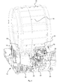
- FIG 5 illustrates a perspective view of the laundry treatment machine 10 with an open side wall according to the first embodiment of the present invention.
- a front panel 42 is arranged at the front side of the laundry treatment machine 10.
- a front door 44 is arranged in the centre of said front panel 42. The front door 44 allows an access to the interior of the laundry drum 40.
- a top panel 46 is arranged on the top side of the laundry treatment machine 10.
- a user interface 48 is arranged at the front side of the laundry treatment machine 10 and above the front panel 42.
- the control unit 52 is arranged besides the user interface 48.
- FIG 6 illustrates another perspective view of the laundry treatment machine 10 with the open side wall according to the first embodiment of the present invention.
- the combination of FIG 5 and FIG 6 clarify the arrangement of the components.
- the present invention allows the adaption of the relevant parameters for operating the laundry treating machine 10 to the detected frequency of the main power supply.
- the inventive laundry treating machine may be provided for the main power supply frequencies of 50 Hz and also 60 Hz.
- the present invention allows an easy adaption of the same laundry treating machine to main power supplies in different world areas.
- the control unit 52 and/or the inverter control device 24 may be realized by low complexity and by low costs.
Landscapes
- Engineering & Computer Science (AREA)
- Textile Engineering (AREA)
- Control Of Washing Machine And Dryer (AREA)
- Detail Structures Of Washing Machines And Dryers (AREA)
Abstract
The present invention relates to a laundry treating machine (10) comprising at least one electric motor (22) and at least one inverter control device (24) for controlling the rotational speed of said electric motor (22), wherein the electric motor (22) is provided for driving a laundry drum (40), an air stream fan (20), a cooling air fan (34) and/or a heat pump compressor (18), and wherein the inverter control device (24) is controlled again by a control unit (52) of the laundry treating machine (10). The control unit (52) comprises or corresponds with a detection device for detecting the frequency of a mains power supply connected to the laundry treating machine (10), wherein the control unit (52) and/or the inverter control device (24) control the electric motor (22) on the basis of one or more operating parameters depending on the detected frequency of the mains power supply.
Description
- The present invention relates to a laundry treating machine comprising at least one electric motor and at least one inverter control device for controlling the rotational speed of said electric motor according to the preamble of
claim 1. - A condense-type laundry dryer includes a closed air stream circuit, wherein an air stream for drying the laundry is circulated cyclically through the laundry drum containing laundry to be treated. Within the air stream circuit a heat exchanger of air-to-air type removes moisture from the air stream leaving the drum. The air-to-air heat exchanger acts as a condenser. A heating device, e.g. an electric heater, is provided in the air stream circuit for heating up the air stream after it has been dehumidified. An open cooling air circuit is provided for cooling the air-to-air heat exchanger.
- A laundry dryer with a heat pump system includes a similar closed air stream circuit described above, but the air-to-air heat exchanger and the heating device are replaced by an evaporator and a condenser, respectively, of the heat pump system.
- In the condense-type laundry dryer, the laundry drum, a cooling air fan of the condenser and a drying air stream fan are driven by the same asynchronous electric motor. In the laundry dryer with the heat pump system the laundry drum and the drying air stream fan are driven by the same electric motor. A further electric motor is provided for driving the compressor of the heat pump system.
- In a washing machine or a washer-dryer an electric motor is provided for rotating the laundry drum in both directions of rotation.
- The rotational speed of the electric motor depends on the electrical parameters, i.e. voltage, current and frequency, of the main power supply, to which the electric motor is connected. In particular, a frequency change of the main power supply alters the rotational speed of the electric motor. The drying and/or washing performances to be granted by the laundry treating machine are set with a nominal power supply frequency of 50 Hz. If the laundry treating machine has to be supplied with a higher power supply frequency, for instance 60 Hz, the rotational speed of the electric motor would modify the working conditions of the laundry treating machine, since the rotational speed of the laundry drum, the flow rate of the air stream, the flow rate of the cooling air and/or the flow rate compressed refrigerant would change, in particular increase. These modifications alter the laundry treating machine performances and may cause unwanted noise due to the air flow.
- There is a need to adapt the laundry treating machine, since the power supply frequency is higher than the nominal power supply frequency in some countries. In order to adapt the laundry treating machine to be powered with a power supply frequency higher than the nominal power supply frequency without the need of resetting all the drying and/or washing cycles, a mechanical reducer may be installed to change the higher rotational speed of the electric motor into the nominal speed to be supplied to motor driven device(s). For example, the rotational speed that the motor would have at the nominal power supply frequency is adjusted. However, such solution has a longer assembly time, an increased number of components and the need of modifying the assembly line.
-
EP 2 487 290 A1 discloses a laundry dryer including an electric motor controlled by an inverter circuit for changing the rotational speed of said electric motor. However, this laundry dryer has no provisions for adapting the operation to different power supply frequencies. If the laundry dryer is supplied with a main power supply frequency, which differs from the nominal main power supply frequency, then the laundry dryer is prevented from operating for safety reasons. This is due to the fact that all the electric and electronic components for carrying out a treating process on a laundry mass are set for being operated with a nominal power supply frequency that needs to be univocally fixed. This requires the manufacturer to install an appropriate control unit for each frequency that is supposed to power the machine. This would determinate a complication in the machine assembly process. - It is an object of the present invention to provide a laundry treating machine, which overcomes the problems mentioned above.
- The object of the present invention is achieved by the laundry treating machine according to
claim 1. - According to the present invention the control unit comprises or corresponds with a detection device for detecting the frequency of a main power supply connected to the laundry treating machine, wherein the control unit and/or the inverter control device control the electric motor on the basis of one or more operating parameters depending on the detected frequency of the main power supply.
- Operating parameters that are set depending on the detected frequency of the main power supply may consist in the rotational speed of the motor, motor power consumption, motor activation/deactivation time periods or rate. Further operating parameters to control the electric motor and/or other electric/electronic components of the laundry drying machine such drying air or water electric heaters, switches, relays, sensors and so on, may include activation/deactivation periods of time elapsed from a predetermined status condition of the machine power supply, electric motor and/or other electric/electronic components of the laundry drying machine. In particular, the status condition of the machine power supply may be the zero-crossing condition of an alternating current/voltage over time, i.e., in other words, the instant of time in which the current/voltage of an alternating power supply is zero in a graph showing the course of current/voltage over time.
- In this way it is possible not only to easy adapt the same laundry treating machine to different main power supplies in different world areas thereby ensuring that the performance of the process to be carried out on laundry remains unchanged, but it is also possible to set specific operating parameters for each main power supply so as to allow the same machine adapting processes to be carried out on laundry to local requirements or needs. For example, different motor activation/deactivation time periods or rate may be associated to each main power supply frequency.
- The core of the present invention is the adaption of the relevant parameters for operating the laundry treating machine to the detected frequency of the main power supply. In particular, the inventive laundry treating machine may be provided for the main power supply frequencies of 50 Hz as well as of 60 Hz, for instance. The present invention allows an easy adaption of the same laundry treating machine to main power supplies in different world areas. The control unit and/or the inverter control device may be realized by low complexity and by low costs. It is not necessary to provide different versions of the laundry treating machine for different frequencies of the main power supply.
- Furthermore, the control unit may control further electric and/or electronic components on the basis of one or more operating parameters depending on the detected frequency of the main power supply.
- In particular, the further electric and/or electronic components are provided for controlling, activating and/or deactivating functions of the laundry treating process.
- For example, the further electric and/or electronic components are provided for controlling, activating and/or deactivating one or more detection devices and/or electronic diagnostic devices of the laundry treating machine.
- Preferably, the control unit comprises at least one memory device, in which at least one program and/or data base are stored or storable, wherein said program and/or data base represent one or more correlations between the operating parameters and the frequency of the main power supply.
- For instance, the memory device is programmable by a manufacturer and/or installer of the laundry treating machine.
- For safety reasons, the laundry treating machine may be activated by the control unit only, if the operating parameters are suitable for the detected frequency of the main power supply.
- In particular, the control unit is programmed or programmable for recognizing the actually detected frequency of the main power supply and for adjusting the operational parameters according to the detected frequency of the main power supply.
- The control unit may be provided for adjusting the operational parameters according to a range between 50 Hz and 60 Hz for the detected frequency of the main power supply.
- Further, the control unit may be an integrated part of an electronic power board being in signal communication with a user interface of the laundry treating machine.
- Moreover, the control unit may be provided for communicating a reference rotational speed signal to the inverter control device.
- Preferably, the laundry treating machine includes at least one optical device for indicating the detected frequency of the main power supply and/or the adjusted parameters.
- In particular, the electric motor is provided for simultaneous driving the laundry drum and at least one fan.
- For example, the laundry treating machine is a laundry dryer including a heat pump system.
- According to another example, the laundry treating machine is a condense-type laundry dryer.
- The novel and inventive features believed to be the characteristic of the present invention are set forth in the appended claims.
- The invention will be described in further detail with reference to the drawings, in which
- FIG 1
- illustrates a perspective view of a basement portion of a laundry treatment machine according to a first embodiment of the present invention,
- FIG 2
- illustrates a perspective view of the basement portion of the laundry treatment machine according to a second embodiment of the present invention,
- FIG 3
- illustrates another perspective view of the basement portion of the laundry treatment machine according to the second embodiment of the present invention,
- FIG 4
- illustrates a perspective view of the basement portion with a laundry drum of the laundry treatment machine according to the first embodiment of the present invention,
- FIG 5
- illustrates a perspective view of the laundry treatment machine with an open side wall according to the first embodiment of the present invention, and
- FIG 6
- illustrates another perspective view of the laundry treatment machine with the open side wall according to the first embodiment of the present invention.
-
FIG 1 illustrates a perspective view of abasement portion 12 of alaundry treatment machine 10 according to a first embodiment of the present invention. Thelaundry treatment machine 10 according to a first embodiment is a laundry dryer including a heat pump system. Thebasement portion 12 is the lower part of thelaundry treatment machine 10. Thebasement portion 12 is arranged below alaundry drum 40 of thelaundry treatment machine 10. - The
basement portion 12 includes a first air-to-refrigerant heat exchanger 14, a second air-to-refrigerant heat exchanger 16, aheat pump compressor 18, anair stream fan 20 and anair stream channel 26. The first air-to-refrigerant heat exchanger 14, the second air-to-refrigerant heat exchanger 16, theheat pump compressor 18, theair stream fan 20 and theair stream channel 26 are components of the heat pump system. Further, thebasement portion 12 includes anelectric motor 22 and aninverter control device 24. Theinverter control device 24 is provided for controlling theelectric motor 22. - The first air-to-
refrigerant heat exchanger 14, the second air-to-refrigerant heat exchanger 16 and theheat pump compressor 18 are parts of a closed refrigerant circuit. Theheat pump compressor 18 is electrically powered and compresses and heats up the refrigerant. The first air-to-refrigerant heat exchanger 14 acts as an evaporator, for instance. The first air-to-refrigerant heat exchanger 14 cools down and dehumidifies the air stream in theair stream channel 26, after said air stream has passed thelaundry drum 40. At the same time, the first air-to-refrigerant heat exchanger 14 heats up and vaporises the refrigerant. The second air-to-refrigerant heat exchanger 16 acts as a condenser, for example. The second air-to-refrigerant heat exchanger 16 heats up the air stream in theair stream channel 26, before the air stream is reinserted into thelaundry drum 40 again. At the same time, the second air-to-refrigerant heat exchanger 16 cools down and condenses the refrigerant. - A
first shaft 28 and asecond shaft 30 are connected to theelectric motor 22. Thefirst shaft 28 and thesecond shaft 30 are arranged on opposite sides of theelectric motor 22. Thefirst shaft 28 is provided for driving anendless belt 32 enclosing thelaundry drum 40. Thesecond shaft 30 is directly connected to the centre of theair stream fan 20. Thus, theelectric motor 22 drives thelaundry drum 40 and the dryingair stream fan 20. Theinverter control device 24 controls the rotation speed of theelectric motor 22. Theinverter control device 24 is controlled again by acontrol unit 52, which is not explicitly shown inFIG 1 . - The
control unit 52 comprises or corresponds with a detection device for detecting the frequency of a main power supply connected to thelaundry treating machine 10. Thecontrol unit 52 and/or theinverter control device 24 control theelectric motor 22 on the basis of at least one operating parameter. Said operating parameter depends on the detected frequency of the main power supply. - Additionally, the
control unit 52 controls further electric and/or electronic components on the basis of at least one operating parameter depending on the detected frequency of the main power supply. The further electric and/or electronic components may be provided for controlling, activating and/or deactivating functions of the laundry treating process. Said further electric and/or electronic components may also be provided for controlling, activating and/or deactivating one or more detection devices and/or electronic diagnostic devices of thelaundry treating machine 10. For example, in order to let a diagnostic device monitoring the operation of a power board perform a detection of main voltage supply at a higher (or lower) peak of the sinusoidal course of said main voltage supply over time so as to reduce detection errors, the detection activation of such diagnostic device has to be done after a time period Δt has elapsed from the voltage zero-crossing instant. Since said time period Δt depends from the main power frequency, and it decreases when the main power frequency increases, it is clear that the operating parameter (in this case the time period Δt) of the diagnostic device has to be set on the appropriate value in accordance to the main power supply frequency that has been detected by thecontrol unit 52. If such operating parameter is not changed so as to be synchronised with the actual main power supply frequency powering the laundry treating appliance, the operation of the latter would be negatively influenced or even impossible to be carried out.
An analogous set-up of operating parameters depending on the main power supply frequency has to be performed for controlling the electric motor, for example by adjusting the activation of the relays or other electronic components turning on/off the motor. -
FIG 2 illustrates a perspective view of thebasement portion 12 of thelaundry treatment machine 10 according to a second embodiment of the present invention. Thelaundry treatment machine 10 according to the second embodiment is a condense-type laundry dryer. Thebasement portion 12 forms the lower part of thelaundry treatment machine 10, so that thebasement portion 12 is arranged below thelaundry drum 40. - The
laundry treatment machine 10 of the condense-type includes a heating device, a coolingfan 34, an air-to-air heat exchanger 36 and an opencooling air circuit 38 instead of the first air-to-refrigerant heat exchanger 14, the second air-to-refrigerant heat exchanger 16 and theheat pump compressor 18 of the first embodiment inFIG 1 . The air-to-air heat exchanger 36 allows a heat exchange between the drying air stream in theair stream channel 26 and another air stream in the opencooling air circuit 38. Said opencooling air circuit 38 is provided for cooling the air-to-air heat exchanger 36. The air-to-air heat exchanger 36 acts as a condenser. The opencooling air circuit 38 is driven by a coolingair fan 34. The heating device is preferably an electric heater and provided in theair stream channel 26 for heating up the air stream in theair stream channel 26 after it has been dehumidified. -
FIG 3 illustrates another perspective view of thebasement portion 12 of thelaundry treatment machine 10 according to the second embodiment of the present invention.FIG 3 clarifies the positions of the components in thebasement portion 12 of the condense-type laundry dryer. - In particular,
FIG 3 clarifies the arrangement of theair stream channel 26 and the opencooling air circuit 38. Theair stream channel 26 and the opencooling air circuit 38 penetrate perpendicular to each other the air-to-air heat exchanger 36. Theair stream channel 26 is driven by theair stream fan 20. In a similar way, the opencooling air circuit 38 is driven by the coolingair fan 34. - The
electric motor 22 is also connected to thefirst shaft 28 and to thesecond shaft 30. Thefirst shaft 28 and thesecond shaft 30 are arranged on opposite sides of saidelectric motor 22. Thefirst shaft 28 is provided for driving theendless belt 32 enclosing thelaundry drum 40. Further, thefirst shaft 28 is directly connected to theair stream fan 20 arranged in theair stream channel 26. Thesecond shaft 30 is directly connected to the centre of the coolingair fan 34 arranged in the opencooling air circuit 38. Thus, theelectric motor 22 drives thelaundry drum 40, theair stream fan 20 and the coolingair fan 34. Theinverter control device 24 controls the rotation speed of theelectric motor 22, wherein theinverter control device 24 is controlled again by thecontrol unit 52 mentioned above, which is not explicitly shown inFIG 2 andFIG 3 . -
FIG 4 illustrates a perspective view of thebasement portion 12 with thelaundry drum 40 of thelaundry treatment machine 10 according to the first embodiment of the present invention. Thelaundry drum 40 is arranged above thebasement portion 12 shown inFIG 1 . Theendless belt drive 32 encloses thelaundry drum 40 and thefirst shaft 28. Thelaundry drum 40 is supported by fourrollers 50. -
FIG 5 illustrates a perspective view of thelaundry treatment machine 10 with an open side wall according to the first embodiment of the present invention. Afront panel 42 is arranged at the front side of thelaundry treatment machine 10. Afront door 44 is arranged in the centre of saidfront panel 42. Thefront door 44 allows an access to the interior of thelaundry drum 40. Atop panel 46 is arranged on the top side of thelaundry treatment machine 10. Auser interface 48 is arranged at the front side of thelaundry treatment machine 10 and above thefront panel 42. Thecontrol unit 52 is arranged besides theuser interface 48. -
FIG 6 illustrates another perspective view of thelaundry treatment machine 10 with the open side wall according to the first embodiment of the present invention. The combination ofFIG 5 andFIG 6 clarify the arrangement of the components. - The present invention allows the adaption of the relevant parameters for operating the
laundry treating machine 10 to the detected frequency of the main power supply. For instance, the inventive laundry treating machine may be provided for the main power supply frequencies of 50 Hz and also 60 Hz. The present invention allows an easy adaption of the same laundry treating machine to main power supplies in different world areas. Thecontrol unit 52 and/or theinverter control device 24 may be realized by low complexity and by low costs. - Although illustrative embodiments of the present invention have been described herein with reference to the accompanying drawings, it is to be understood that the present invention is not limited to those precise embodiments, and that various other changes and modifications may be affected therein by one skilled in the art without departing from the scope of the invention as claimed. All such changes and modifications are intended to be included within the scope of the invention as defined by the appended claims.
-
- 10
- laundry treating machine
- 12
- basement portion
- 14
- first air-to-refrigerant heat exchanger
- 16
- second air-to-refrigerant heat exchanger
- 18
- heat pump compressor
- 20
- air stream fan
- 22
- electric motor
- 24
- inverter control device
- 26
- air stream channel
- 28
- first shaft
- 30
- second shaft
- 32
- endless belt
- 34
- cooling air fan
- 36
- air-to-air heat exchanger
- 38
- open cooling air circuit
- 40
- laundry drum
- 42
- front panel
- 44
- front door
- 46
- top panel
- 48
- user interface
- 50
- roller
- 52
- control unit
Claims (15)
- A laundry treating machine (10) comprising at least one electric motor (22) and at least one inverter control device (24) for controlling the rotational speed of said electric motor (22), wherein the electric motor (22) is provided for driving a laundry drum (40), an air stream fan (20), a cooling air fan (34) and/or a heat pump compressor (18), and wherein the inverter control device (24) is controlled again by a control unit (52) of the laundry treating machine (10),
characterized in that
the control unit (52) comprises or corresponds with a detection device for detecting the frequency of a main power supply connected to the laundry treating machine (10), wherein the control unit (52) and/or the inverter control device (24) control the electric motor (22) on the basis of one or more operating parameters depending on the detected frequency of the main power supply. - The laundry treating machine according to claim 1,
characterized in that
the control unit (52) controls further electric and/or electronic components on the basis of one or more operating parameters depending on the detected frequency of the main power supply. - The laundry treating machine according to claim 2,
characterized in that
the further electric and/or electronic components are provided for controlling, activating and/or deactivating functions of the laundry treating process. - The laundry treating machine according to claim 2 or 3,
characterized in that
the further electric and/or electronic components are provided for controlling, activating and/or deactivating one or more detection devices and/or electronic diagnostic devices of the laundry treating machine (10). - The laundry treating machine according to any one of the preceding claims,
characterized in that
the control unit (52) comprises at least one memory device, in which at least one program and/or data base are stored or storable, wherein said program and/or data base represent one or more correlations between the operating parameters and the frequency of the main power supply. - The laundry treating machine according to claim 5,
characterized in that
the memory device is programmable by a manufacturer and/or installer of the laundry treating machine (10). - The laundry treating machine according to any one of the preceding claims,
characterized in that
the laundry treating machine (10) is activated by the control unit (52) only, if the operating parameters are suitable for the detected frequency of the main power supply. - The laundry treating machine according to any one of the preceding claims,
characterized in that
the control unit (52) is programmed or programmable for recognizing the actually detected frequency of the main power supply and for adjusting the operational parameters according to the detected frequency of the main power supply. - The laundry treating machine according to any one of the preceding claims,
characterized in that
the control unit (52) is provided for adjusting the operational parameters according to a range between 50 Hz and 60 Hz for the detected frequency of the main power supply. - The laundry treating machine according to any one of the preceding claims,
characterized in that
the control unit (52) is an integrated part of an electronic power board being in signal communication with a user interface (48) of the laundry treating machine (10). - The laundry treating machine according to any one of the preceding claims,
characterized in that
the control unit (52) is provided for communicating a reference rotational speed signal to the inverter control device (24). - The laundry treating machine according to any one of the preceding claims,
characterized in that
the laundry treating machine (10) includes at least one optical device for indicating the detected frequency of the main power supply and/or the adjusted parameters. - The laundry treating machine according to any one of the preceding claims,
characterized in that
the electric motor (22) is provided for simultaneous driving the laundry drum (40) and at least one fan (20, 34). - The laundry treating machine according to any one of the preceding claims,
characterized in that
the laundry treating machine (10) is a laundry dryer including a heat pump system. - The laundry treating machine according to any one of the claims 1 to 13,
characterized in that
the laundry treating machine (10) is a condense-type laundry dryer.
Priority Applications (5)
| Application Number | Priority Date | Filing Date | Title |
|---|---|---|---|
| EP12194962.2A EP2738304A1 (en) | 2012-11-30 | 2012-11-30 | A laundry treating machine with an electric motor and an inverter control device |
| US14/647,656 US20150322616A1 (en) | 2012-11-30 | 2013-11-26 | A Laundry Treating Machine with an Electric Motor and an Inverter Control Device |
| BR112015012442-9A BR112015012442B1 (en) | 2012-11-30 | 2013-11-26 | CLOTHING TREATMENT MACHINE |
| PCT/EP2013/074743 WO2014082999A1 (en) | 2012-11-30 | 2013-11-26 | A laundry treating machine with an electric motor and an inverter control device |
| EP13795768.4A EP2925926B1 (en) | 2012-11-30 | 2013-11-26 | A laundry treating machine with an electric motor and an inverter control device |
Applications Claiming Priority (1)
| Application Number | Priority Date | Filing Date | Title |
|---|---|---|---|
| EP12194962.2A EP2738304A1 (en) | 2012-11-30 | 2012-11-30 | A laundry treating machine with an electric motor and an inverter control device |
Publications (1)
| Publication Number | Publication Date |
|---|---|
| EP2738304A1 true EP2738304A1 (en) | 2014-06-04 |
Family
ID=47594335
Family Applications (2)
| Application Number | Title | Priority Date | Filing Date |
|---|---|---|---|
| EP12194962.2A Withdrawn EP2738304A1 (en) | 2012-11-30 | 2012-11-30 | A laundry treating machine with an electric motor and an inverter control device |
| EP13795768.4A Active EP2925926B1 (en) | 2012-11-30 | 2013-11-26 | A laundry treating machine with an electric motor and an inverter control device |
Family Applications After (1)
| Application Number | Title | Priority Date | Filing Date |
|---|---|---|---|
| EP13795768.4A Active EP2925926B1 (en) | 2012-11-30 | 2013-11-26 | A laundry treating machine with an electric motor and an inverter control device |
Country Status (4)
| Country | Link |
|---|---|
| US (1) | US20150322616A1 (en) |
| EP (2) | EP2738304A1 (en) |
| BR (1) | BR112015012442B1 (en) |
| WO (1) | WO2014082999A1 (en) |
Cited By (2)
| Publication number | Priority date | Publication date | Assignee | Title |
|---|---|---|---|---|
| WO2015018649A1 (en) * | 2013-08-06 | 2015-02-12 | BSH Bosch und Siemens Hausgeräte GmbH | Controlling an electric load of a domestic appliance |
| CN105970579A (en) * | 2016-05-31 | 2016-09-28 | 无锡小天鹅股份有限公司 | Heat pump installation box and heat pump clothes dryer or heat pump washing and drying integrated machine |
Families Citing this family (6)
| Publication number | Priority date | Publication date | Assignee | Title |
|---|---|---|---|---|
| US9670612B2 (en) * | 2014-08-13 | 2017-06-06 | Lg Electronics Inc. | Laundry treatment apparatus and method for controlling a laundry treatment apparatus |
| KR101613966B1 (en) | 2014-12-29 | 2016-04-20 | 엘지전자 주식회사 | Clothes treating apparatus |
| US10801766B2 (en) * | 2019-01-30 | 2020-10-13 | Regal Beloit America, Inc. | Drive circuit for a variable speed fan motor |
| US11959679B2 (en) | 2019-01-30 | 2024-04-16 | Regal Beloit America, Inc. | Drive circuit for a variable speed fan motor |
| KR102737000B1 (en) * | 2019-04-10 | 2024-12-03 | 엘지전자 주식회사 | Laundry Treating Apparatus |
| WO2021029556A1 (en) * | 2019-08-14 | 2021-02-18 | 엘지전자 주식회사 | Heat exchanger and method for manufacturing home appliance including heat exchanger |
Citations (2)
| Publication number | Priority date | Publication date | Assignee | Title |
|---|---|---|---|---|
| US20110010961A1 (en) * | 2009-07-16 | 2011-01-20 | Emerson Electric Co. | Dryer Motor and Control |
| EP2487290A1 (en) | 2011-02-10 | 2012-08-15 | Electrolux Home Products Corporation N.V. | Home laundry drier |
Family Cites Families (6)
| Publication number | Priority date | Publication date | Assignee | Title |
|---|---|---|---|---|
| US4986092A (en) * | 1989-04-12 | 1991-01-22 | Emerson Electric Co. | Speed control for inverter driven washing machine |
| US6163912A (en) * | 1997-09-22 | 2000-12-26 | Matsushita Electric Industrial Co., Ltd. | Washing machine |
| CA2351650C (en) * | 1998-11-17 | 2006-08-22 | Fisher & Paykel Limited | Laundry machine |
| KR100425723B1 (en) * | 2001-07-10 | 2004-04-03 | 엘지전자 주식회사 | Method of detecting the weight of laundry in washing machine of sensorless bldc motor |
| US20080297098A1 (en) * | 2007-06-01 | 2008-12-04 | Robert Keith Hollenbeck | Washing machine apparatus and method |
| US9115455B2 (en) * | 2010-12-09 | 2015-08-25 | Whirlpool Corporation | Method and apparatus for controlling the extraction duration in a laundry treating appliance |
-
2012
- 2012-11-30 EP EP12194962.2A patent/EP2738304A1/en not_active Withdrawn
-
2013
- 2013-11-26 BR BR112015012442-9A patent/BR112015012442B1/en active IP Right Grant
- 2013-11-26 WO PCT/EP2013/074743 patent/WO2014082999A1/en not_active Ceased
- 2013-11-26 US US14/647,656 patent/US20150322616A1/en not_active Abandoned
- 2013-11-26 EP EP13795768.4A patent/EP2925926B1/en active Active
Patent Citations (2)
| Publication number | Priority date | Publication date | Assignee | Title |
|---|---|---|---|---|
| US20110010961A1 (en) * | 2009-07-16 | 2011-01-20 | Emerson Electric Co. | Dryer Motor and Control |
| EP2487290A1 (en) | 2011-02-10 | 2012-08-15 | Electrolux Home Products Corporation N.V. | Home laundry drier |
Cited By (3)
| Publication number | Priority date | Publication date | Assignee | Title |
|---|---|---|---|---|
| WO2015018649A1 (en) * | 2013-08-06 | 2015-02-12 | BSH Bosch und Siemens Hausgeräte GmbH | Controlling an electric load of a domestic appliance |
| CN105970579A (en) * | 2016-05-31 | 2016-09-28 | 无锡小天鹅股份有限公司 | Heat pump installation box and heat pump clothes dryer or heat pump washing and drying integrated machine |
| CN105970579B (en) * | 2016-05-31 | 2018-11-06 | 无锡小天鹅股份有限公司 | Heat pump mounting box and heat pump clothes dryer or heat pump washing-drying integral machine |
Also Published As
| Publication number | Publication date |
|---|---|
| WO2014082999A1 (en) | 2014-06-05 |
| BR112015012442B1 (en) | 2021-08-03 |
| EP2925926B1 (en) | 2016-07-06 |
| BR112015012442A2 (en) | 2017-08-22 |
| US20150322616A1 (en) | 2015-11-12 |
| EP2925926A1 (en) | 2015-10-07 |
Similar Documents
| Publication | Publication Date | Title |
|---|---|---|
| EP2925926B1 (en) | A laundry treating machine with an electric motor and an inverter control device | |
| EP2789728B1 (en) | Method for controlling a motor of a laundry dryer | |
| EP2920356B1 (en) | Method of operating a heat pump laundry dryer and heat pump laundry dryer or heat pump washing machine having drying function | |
| CA2446624C (en) | Clothes dryer apparatus and method | |
| US6745495B1 (en) | Clothes dryer apparatus and method | |
| US8938834B2 (en) | Fabric treating apparatus and method for controlling the same | |
| EP3019656B1 (en) | Appliance for drying laundry with enhanced operation flexibility | |
| EP2920354B1 (en) | Method of operating a heat pump laundry dryer and heat pump laundry dryer or heat pump washing machine having drying function | |
| EP3919669B1 (en) | Laundry treatment apparatus and control method thereof | |
| EP2620535A1 (en) | Laundry treating machine | |
| EP3019655B1 (en) | Heat pump laundry drying appliance with enhanced operation flexibility | |
| CA2446625C (en) | Clothes dryer apparatus and method | |
| KR980009628A (en) | Clothes dryer | |
| KR20090014054A (en) | Control Method of Clothing Processing Equipment | |
| AU2018424693A1 (en) | Laundry drier | |
| EP3124678B1 (en) | Method of operation of a heat pump drying and/or washing appliance and heat pump drying and/or washing appliance | |
| EP1775368B1 (en) | Washing/drying machine or clothes dryer with drying air adjustment system | |
| EP2920357B1 (en) | Heat pump laundry treatment apparatus and method of operating a heat pump laundry treatment apparatus | |
| EP2679718A1 (en) | A laundry or tableware treating machine | |
| US20150028016A1 (en) | Inrush Current Control System | |
| EP3336239B1 (en) | Laundry treatment apparatus and control method of laundry treatment apparatus | |
| EP3314050B1 (en) | Power supply regulation in laundry treatment machines or dishwashers | |
| EP3249089A1 (en) | Laundry treatment appliance | |
| EP2192224A1 (en) | An improved tumble dryer | |
| EP3314051B1 (en) | Power supply regulation in laundry treatment machines or dishwashers |
Legal Events
| Date | Code | Title | Description |
|---|---|---|---|
| PUAI | Public reference made under article 153(3) epc to a published international application that has entered the european phase |
Free format text: ORIGINAL CODE: 0009012 |
|
| 17P | Request for examination filed |
Effective date: 20121130 |
|
| AK | Designated contracting states |
Kind code of ref document: A1 Designated state(s): AL AT BE BG CH CY CZ DE DK EE ES FI FR GB GR HR HU IE IS IT LI LT LU LV MC MK MT NL NO PL PT RO RS SE SI SK SM TR |
|
| AX | Request for extension of the european patent |
Extension state: BA ME |
|
| STAA | Information on the status of an ep patent application or granted ep patent |
Free format text: STATUS: THE APPLICATION IS DEEMED TO BE WITHDRAWN |
|
| 18D | Application deemed to be withdrawn |
Effective date: 20141205 |