EP2738052A1 - Motor control device - Google Patents
Motor control device Download PDFInfo
- Publication number
- EP2738052A1 EP2738052A1 EP12818334.0A EP12818334A EP2738052A1 EP 2738052 A1 EP2738052 A1 EP 2738052A1 EP 12818334 A EP12818334 A EP 12818334A EP 2738052 A1 EP2738052 A1 EP 2738052A1
- Authority
- EP
- European Patent Office
- Prior art keywords
- motor
- lead angle
- rotation speed
- rotation
- unit configured
- Prior art date
- Legal status (The legal status is an assumption and is not a legal conclusion. Google has not performed a legal analysis and makes no representation as to the accuracy of the status listed.)
- Granted
Links
Images



Classifications
-
- B—PERFORMING OPERATIONS; TRANSPORTING
- B60—VEHICLES IN GENERAL
- B60S—SERVICING, CLEANING, REPAIRING, SUPPORTING, LIFTING, OR MANOEUVRING OF VEHICLES, NOT OTHERWISE PROVIDED FOR
- B60S1/00—Cleaning of vehicles
- B60S1/02—Cleaning windscreens, windows or optical devices
- B60S1/04—Wipers or the like, e.g. scrapers
- B60S1/06—Wipers or the like, e.g. scrapers characterised by the drive
- B60S1/08—Wipers or the like, e.g. scrapers characterised by the drive electrically driven
-
- H—ELECTRICITY
- H02—GENERATION; CONVERSION OR DISTRIBUTION OF ELECTRIC POWER
- H02P—CONTROL OR REGULATION OF ELECTRIC MOTORS, ELECTRIC GENERATORS OR DYNAMO-ELECTRIC CONVERTERS; CONTROLLING TRANSFORMERS, REACTORS OR CHOKE COILS
- H02P7/00—Arrangements for regulating or controlling the speed or torque of electric DC motors
- H02P7/03—Arrangements for regulating or controlling the speed or torque of electric DC motors for controlling the direction of rotation of DC motors
Definitions
- the present invention relates to a motor control device which controls rotation of a motor that operates a wiper device and the like provided in a vehicle.
- Vehicles are conventionally provided with a wiper device attached to the windshield to wipe off rain, splashes from a preceding vehicle, etc. in order to provide the driver with an optimum field of vision.
- the wiper device has a wiper arm whose oscillation is controlled by a wiper-driving device and a wiper blade abutting the windshield is mounted on a tip end of the wiper arm.
- the wiper arm on which the wiper blade is mounted performs a reciprocating motion, so that wiping of the windshield is performed.
- a link mechanism changes a rotational motion of a motor to a reciprocating motion and thus the wiper arm performs a wiping operation.
- the present invention has been made in view of such circumstances, and an object of the invention is to provide a motor control device capable of suppressing electric power consumption and heat generation by constantly rotating a motor in a state in which efficiency is good.
- a motor control device which controls a motor by performing switching between forward rotation and reverse rotation so as to cause an object to be controlled to reciprocate
- the motor control device including a lead angle map storage unit configured to store a lead angle map in which a motor rotation speed and a lead angle to be set are associated for each of the forward rotation and the reverse rotation, a target rotation speed-setting unit configured to set a target rotation speed of the motor based on an input signal from outside, a lead angle-setting unit configured to obtain the lead angle associated with the set target rotation speed by referring to the lead angle map and set the lead angle as a lead angle of the motor, and a driving control unit configured to control rotation of the motor so as to achieve the set target rotation speed and the set lead angle.
- the object to be controlled is a wiper device provided in a vehicle.
- the present invention there is an effect in that it is possible to constantly rotate a motor in a state in which characteristics of the motor are good and suppress electric power consumption and heat generation because a lead angle map in which a motor rotation speed (the number of rotations) and a lead angle to be set are associated is stored for each of forward rotation and reverse rotation and the lead angle corresponding to a newly obtained target rotation speed is also varied according to variation in the target rotation speed.
- Fig. 1 is a block diagram illustrating a configuration of the embodiment.
- a wiper device provided on a vehicle will be described as an object to be controlled according to rotation of a motor to be controlled by the motor control device.
- reference sign 1 denotes a wiper arm which wipes a windshield.
- Reference sign 2 denotes a brushless motor for causing the wiper arm 1 to perform a wiping operation, and which is possible to change a lead angle by varying a flowing electric current pattern.
- the wiper arm 1 is connected to a rotary shaft of the motor 2 through a link mechanism, and performs the wiping operation by switching a rotational direction of the rotary shaft between forward rotation and reverse rotation and reciprocating the wiper arm 1.
- Reference sign 21 denotes an angle sensor which detects and outputs the rotational angle of the rotary shaft of the motor.
- the rotational angle of the rotary shaft of the motor 2 and an operation angle of the wiper arm 1 will be described as being consistent. That is, the rotary shaft of the motor 2 is assumed to reciprocate at the rotational angle between 0 degrees and 150 degrees by performing forward and reverse rotations if the operation angle of the wiper arm 1 is 0 degrees to 150 degrees.
- Reference sign 3 denotes a motor-driving unit which drives the motor 2 by controlling electric power to be supplied according to a driving command.
- Reference sign 4 denotes a control unit which outputs the driving command to the motor-driving unit 3 in order to control the rotation of the motor 2, and includes a microcomputer.
- Reference sign 41 denotes a signal input unit which inputs a signal which is transmitted and received within a vehicle via an in-vehicle local area network (LAN), for example, a controller area network (CAN) or a local interconnect network (LIN).
- LAN local area network
- CAN controller area network
- LIN local interconnect network
- the signal input by the signal input unit 41 includes a signal representing a state of a wiper switch which issues an instruction to start/stop a wiping operation to the wiper device or a signal representing a speed (a low speed, a high speed, intermittence, or the like) of the wiping operation.
- Reference sign 42 denotes a driving control unit which controls the wiping operation of the wiper arm 1 by controlling the operation of the motor 2 based on a signal input in the signal input unit 41.
- Reference sign 43 denotes a parameter storage unit which associates and stores a pattern of the input signal input in the signal input unit 41 and parameters for controlling the motor 2 in advance.
- Reference sign 44 denotes a lead angle storage unit which stores lead angle map data defining a relationship between the number of rotations of the motor and the lead angle.
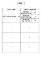
- Fig. 2 is a diagram illustrating the table structure of the parameter storage unit 43 illustrated in Fig. 1 .
- control parameters are associated and stored for each input signal pattern.
- the input signal pattern is made by performing case analysis on input signals.
- the case analysis is made for each signal value (for example, Lo, Hi, or intermittence).
- all of the cases are associated and stored in advance when it is necessary to control an operation of the wiper device according to a signal input to the signal input unit 41.
- the “maximum rotation speed” is a maximum value of the rotation speed of the motor 2 when the wiper arm 1 operates from a current position or a predetermined position to a target position.
- the rotation speed is represented by the number of rotations [rpm].
- the "operation start position” is a position of the wiper arm 1 when a predetermined operation is started.
- the position of the wiper arm 1 is represented by an angle
- a storage position of the wiper arm 1 is 0 degrees
- a return position of the wiper arm 1 is 150 degrees in a maximum wiping range.
- the "operation end position” is a position of the wiper arm 1 when a predetermined operation ends. For example, when the wiper arm is caused to perform a wiping operation in a maximum wiping range, the "operation start position" is 0 degrees and the “operation end position” is 150 degrees.
- Fig. 3 is a diagram illustrating variation in the rotation speed of the motor 2 when the wiper arm 1 is operated from the operation start position to the operation end position.
- the driving control unit 42 first obtains a deceleration start position through an arithmetic operation from the operation start position and the operation end position. Then, the rotation speed is accelerated so that the rotation speed of the motor 2 is set to the maximum rotation speed at the angle of the deceleration start position.
- the rotation speed is decelerated so that the rotation speed is changed to deceleration and the rotation speed at the angle of the operation end position becomes 0.
- the operation of the wiper arm 1 replaces the operation start position and the operation end position of the operation illustrated in Fig. 3 and thus the wiper arm 1 can reciprocate to perform the wiping operation.
- Fig. 4 is an explanatory diagram illustrating the configuration of the lead angle map which defines the number of rotations of the motor and the lead angle stored in the lead angle map storage unit 44 illustrated in Fig. 1 .
- a relationship between the number of rotations of the motor (rpm) and a lead angle (deg) is defined in advance, and a positive lead angle is defined to increase when the number of rotations during forward rotation increases.
- a negative lead angle is defined to increase (an absolute value of a negative lead angle is defined to increase).
- the signal input unit 41 reads an input signal, and outputs the read input signal to the driving control unit 42 (step S1).
- the driving control unit 42 specifies a pattern of the input signal output from the signal input unit 41, and reads control parameters associated with the input signal pattern consistent with the specified input signal pattern from the parameter storage unit 43 (step S2).
- a maximum rotation speed of "65,” an operation start position of "0,” and an operation end position of "150" will be described as the control parameters having been read.
- the driving control unit 42 calculates a deceleration start position from the operation start position of "0" and the operation end position of "150” (step S3).
- the driving control unit 42 outputs a command for setting a predetermined initial value as the target rotation speed to the motor-driving unit 3 (step S4). Thereby, the motor 2 starts rotation.
- the driving control unit 42 reads an angle value output by the angle sensor 21 (step S5).
- the angle value output by the angle sensor 21 corresponds to a value representing a position of the wiper arm 1.
- the driving control unit 42 determines whether the read angle value has reached the deceleration start position (step S6). If the determination result indicates that the deceleration start position has not been reached, the driving control unit 42 waits for a trigger of the control cycle to be input while determining whether the trigger of the control cycle has been input (steps S7 and S8).
- the driving control unit 42 obtains a new target rotation speed (the number of rotations) by adding a predetermined addition amount to the target rotation speed (the number of rotations) of the current time point (step S9). Then, the driving control unit 42 obtains a lead angle corresponding to the newly obtained number of rotations by referring to the lead angle map stored in the lead angle map storage unit 44 (step S10). Subsequently, the driving control unit 42 outputs a command for setting the obtained target rotation speed value and lead angle as a new target rotation speed and lead angle to the motor-driving unit 3 (step S11).
- the driving control unit 42 iterates processing operations of steps S5 to S11 until the deceleration start position is reached. Thereby, the motor 2 reaches the deceleration start position while the rotation speed increases from the operation start position, as illustrated in Fig. 3 . At this time, because an optimum lead angle corresponding to the number of rotations is set, the motor 2 can efficiently rotate.
- the driving control unit 42 reads the angle value output by the angle sensor 21 (step S12). Then, the driving control unit 42 determines whether the read angle value has reached the operation end position (step S13). If the determination result indicates that the operation end position has not been reached, the driving control unit 42 waits for a trigger of the control cycle to be input while determining whether the trigger of the control cycle has been input (steps S 14 and S 15).
- a new target rotation speed (the number of rotations) is obtained by subtracting a predetermined subtraction amount from the target rotation speed (the number of rotations) of the current time point (step S16).
- the driving control unit 42 obtains a lead angle corresponding to the newly obtained number of rotations by referring to the lead angle map stored in the lead angle map storage unit 44 (step S17).
- the driving control unit 42 outputs a command for setting the obtained target rotation speed value and lead angle as a new target rotation speed and lead angle to the motor-driving unit 3 (step S 18).
- the driving control unit 42 iterates processing operations of steps S12 to S 18.
- the rotation of the motor 2 is stopped. Thereby, the motor 2 reaches the operation end position while the rotation speed decreases, as illustrated in Fig. 3 . At this time, because an optimum lead angle corresponding to the number of rotations is set, the motor 2 can efficiently rotate.
- the parameter storage unit 43 in which five control parameters are associated and stored for each input signal pattern is provided in the control unit 4, the five control parameters are selected according to an input signal, and the rotation of the motor 2 is controlled based on the selected control parameters in the above description
- the five control parameters may be input from the outside (a computer which generally controls the operation of the vehicle, or the like) of the control unit 4 and the driving control unit 42 may be configured to control the rotation of the motor 2 based on the input five control parameters.
- the target rotation speed is obtained by an arithmetic operation inside the driving control unit 42.
- the new target rotation speed is obtained by adding or subtracting a predetermined amount in the above description, a value of the target rotation speed determined for each angle in advance may be used based on an output in the angle sensor 21.
- the lead angle map illustrated in Fig. 4 is shown as an example in which the number of rotations of the motor and the lead angle to be set are associated for each of the forward rotation and the reverse rotation, it is possible to constantly rotate a motor in a state in which characteristics of the motor are good and suppress power consumption and heat generation if a lead angle map in which the number of rotations of the motor of the forward rotation and the positive lead angle are associated is used in the case of rotation in only one direction.
- a lead angle map in which a motor rotation speed (the number of rotations) and a lead angle are associated is stored for each of forward and reverse rotations within the control unit 4 and the lead angle corresponding to a newly obtained target rotation speed is also varied according to variation in a target rotation speed.
- the wiper control process may be implemented by recording a program for implementing the function of the control unit 4 in Fig. 1 on a computer-readable recording medium and causing a computer system to read and execute the program recorded on the recording medium.
- computer system used herein may include an operating system (OS) and/or hardware such as peripheral devices.
- computer-readable recording medium refers to a storage device including a flexible disk, a magneto-optical disc, a read only memory (ROM), a portable medium such as a compact disc-ROM (CD-ROM), and a hard disk embedded in the computer system.
- computer-readable recording medium may include a computer-readable recording medium for holding programs for a predetermined time such as a volatile memory (random access memory (RAM)) inside a computer system including a server and a client when a program is transmitted via a network such as the Internet or a communication line such as a telephone line.
- RAM random access memory
- the above-described program may be transmitted from a computer system storing the program in a storage device or the like to other computer systems via a transmission medium or transmission waves of the transmission medium.
- transmission medium for transmitting the program refers to a medium having a function of transmitting information like a network (communication network) such as the Internet or a communication line (communication wire) such as a telephone line.
- the above-described program may be used to implement some of the above-described functions.
- the program may be a so-called differential file (differential program) capable of implementing the above-described functions in combination with a program already recorded on the computer system.
- the present invention can be applied to a controlling operation of an object to be controlled via a link mechanism connected to a rotary shaft of a motor and, for example, can also be applied to control an operation of an electric tailgate, a slide door, a power window, etc. provided in a vehicle.
Landscapes
- Engineering & Computer Science (AREA)
- Mechanical Engineering (AREA)
- Power Engineering (AREA)
- Control Of Electric Motors In General (AREA)
- Control Of Direct Current Motors (AREA)
- Control Of Motors That Do Not Use Commutators (AREA)
Abstract
Description
- The present invention relates to a motor control device which controls rotation of a motor that operates a wiper device and the like provided in a vehicle.
- Priority is claimed on Japanese Patent Application No.
2011-163082, filed July 26, 2011 - Vehicles are conventionally provided with a wiper device attached to the windshield to wipe off rain, splashes from a preceding vehicle, etc. in order to provide the driver with an optimum field of vision. The wiper device has a wiper arm whose oscillation is controlled by a wiper-driving device and a wiper blade abutting the windshield is mounted on a tip end of the wiper arm. The wiper arm on which the wiper blade is mounted performs a reciprocating motion, so that wiping of the windshield is performed. A link mechanism changes a rotational motion of a motor to a reciprocating motion and thus the wiper arm performs a wiping operation.
- Because the wiper arm is required to perform a reciprocating motion, a more efficient and highly-functional wiper device is obtained in case that the motor generating a driving force for the reciprocating motion performs switching between the forward rotation and the reverse rotation, which makes the link mechanism for causing the reciprocating motion unnecessary, rather than in case that the reciprocating motion is implemented through the link mechanism by rotating the motor in only one direction. Therefore, the number of wiper devices which cause the wiper arm to reciprocate by switching the rotation of the motor between the forward rotation and the reverse rotation has recently increased (for example, see Patent Literature 1).
- Japanese Unexamined Patent Application, First Publication No.
2010-228527 - Incidentally, when a brush motor is used, it is possible to rotate the motor in a state in which characteristics are good by optimally setting a lead angle. However, there is a problem in that characteristics are degraded during the reverse rotation if the lead angle is optimally set for the forward rotation in case that the motor rotates with switching between the forward rotation and the reverse rotation so as to cause the wiper arm to reciprocate. In order to avoid this problem, it is necessary to use a position of a brush in a state in which there is no lead angle so that there is no difference in motor characteristics between forward rotation and reverse rotation in the wiper device using the motor which performs the forward and reverse rotation.
- However, in the state in which there is no lead angle, there is a problem such as poor efficiency in a high rotation zone, a large amount of electric current needs to flow, and an increase of heat generation.
- The present invention has been made in view of such circumstances, and an object of the invention is to provide a motor control device capable of suppressing electric power consumption and heat generation by constantly rotating a motor in a state in which efficiency is good.
- According to the present invention, a motor control device is provided which controls a motor by performing switching between forward rotation and reverse rotation so as to cause an object to be controlled to reciprocate, the motor control device including a lead angle map storage unit configured to store a lead angle map in which a motor rotation speed and a lead angle to be set are associated for each of the forward rotation and the reverse rotation, a target rotation speed-setting unit configured to set a target rotation speed of the motor based on an input signal from outside, a lead angle-setting unit configured to obtain the lead angle associated with the set target rotation speed by referring to the lead angle map and set the lead angle as a lead angle of the motor, and a driving control unit configured to control rotation of the motor so as to achieve the set target rotation speed and the set lead angle.
- According to the present invention, the object to be controlled is a wiper device provided in a vehicle.
- According to the present invention, there is an effect in that it is possible to constantly rotate a motor in a state in which characteristics of the motor are good and suppress electric power consumption and heat generation because a lead angle map in which a motor rotation speed (the number of rotations) and a lead angle to be set are associated is stored for each of forward rotation and reverse rotation and the lead angle corresponding to a newly obtained target rotation speed is also varied according to variation in the target rotation speed.
-
-
Fig. 1 is a block diagram illustrating a configuration of an embodiment of the present invention. -
Fig. 2 is an explanatory diagram illustrating a table structure of aparameter storage unit 43 illustrated inFig. 1 . -
Fig. 3 is an explanatory diagram illustrating an operation of amotor 2 illustrated inFig. 1 . -
Fig. 4 is an explanatory diagram illustrating a configuration of a lead angle map in which a relationship between the number of rotations of the motor and a lead angle is stored in a lead anglemap storage unit 44 illustrated inFig. 1 . -
Fig. 5 is a flowchart illustrating an operation of a control unit 4 illustrated inFig. 1 . - Hereinafter, a motor control device according to an embodiment of the present invention will be described with reference to the drawings.
Fig. 1 is a block diagram illustrating a configuration of the embodiment. Here, an example of a wiper device provided on a vehicle will be described as an object to be controlled according to rotation of a motor to be controlled by the motor control device. InFig. 1 ,reference sign 1 denotes a wiper arm which wipes a windshield.Reference sign 2 denotes a brushless motor for causing thewiper arm 1 to perform a wiping operation, and which is possible to change a lead angle by varying a flowing electric current pattern. Thewiper arm 1 is connected to a rotary shaft of themotor 2 through a link mechanism, and performs the wiping operation by switching a rotational direction of the rotary shaft between forward rotation and reverse rotation and reciprocating thewiper arm 1. Reference sign 21 denotes an angle sensor which detects and outputs the rotational angle of the rotary shaft of the motor. Here, for simplicity of description, the rotational angle of the rotary shaft of themotor 2 and an operation angle of thewiper arm 1 will be described as being consistent. That is, the rotary shaft of themotor 2 is assumed to reciprocate at the rotational angle between 0 degrees and 150 degrees by performing forward and reverse rotations if the operation angle of thewiper arm 1 is 0 degrees to 150 degrees.Reference sign 3 denotes a motor-driving unit which drives themotor 2 by controlling electric power to be supplied according to a driving command. - Reference sign 4 denotes a control unit which outputs the driving command to the motor-driving
unit 3 in order to control the rotation of themotor 2, and includes a microcomputer.Reference sign 41 denotes a signal input unit which inputs a signal which is transmitted and received within a vehicle via an in-vehicle local area network (LAN), for example, a controller area network (CAN) or a local interconnect network (LIN). The signal input by thesignal input unit 41 includes a signal representing a state of a wiper switch which issues an instruction to start/stop a wiping operation to the wiper device or a signal representing a speed (a low speed, a high speed, intermittence, or the like) of the wiping operation. -
Reference sign 42 denotes a driving control unit which controls the wiping operation of thewiper arm 1 by controlling the operation of themotor 2 based on a signal input in thesignal input unit 41.Reference sign 43 denotes a parameter storage unit which associates and stores a pattern of the input signal input in thesignal input unit 41 and parameters for controlling themotor 2 in advance.Reference sign 44 denotes a lead angle storage unit which stores lead angle map data defining a relationship between the number of rotations of the motor and the lead angle. - Next, a table structure of the
parameter storage unit 43 illustrated inFig. 1 will be described with reference toFig. 2 . -
Fig. 2 is a diagram illustrating the table structure of theparameter storage unit 43 illustrated inFig. 1 . In theparameter storage unit 43, control parameters are associated and stored for each input signal pattern. - The input signal pattern is made by performing case analysis on input signals. When the signal to be input is a wiper switch signal, the case analysis is made for each signal value (for example, Lo, Hi, or intermittence). In this case analysis, all of the cases are associated and stored in advance when it is necessary to control an operation of the wiper device according to a signal input to the
signal input unit 41. - There are three control parameters, namely, a "maximum rotation speed," an "operation start position," and an "operation end position." The "maximum rotation speed" is a maximum value of the rotation speed of the
motor 2 when thewiper arm 1 operates from a current position or a predetermined position to a target position. Here, the rotation speed is represented by the number of rotations [rpm]. The "operation start position" is a position of thewiper arm 1 when a predetermined operation is started. Here, it is assumed that the position of thewiper arm 1 is represented by an angle, a storage position of thewiper arm 1 is 0 degrees, and a return position of thewiper arm 1 is 150 degrees in a maximum wiping range. The "operation end position" is a position of thewiper arm 1 when a predetermined operation ends. For example, when the wiper arm is caused to perform a wiping operation in a maximum wiping range, the "operation start position" is 0 degrees and the "operation end position" is 150 degrees. - Next, the operation of the
motor 2 will be described with reference toFig. 3. Fig. 3 is a diagram illustrating variation in the rotation speed of themotor 2 when thewiper arm 1 is operated from the operation start position to the operation end position. When the three control parameters (the maximum rotation speed, the operation start position, and the operation end position) are specified according to an input signal pattern, thedriving control unit 42 first obtains a deceleration start position through an arithmetic operation from the operation start position and the operation end position. Then, the rotation speed is accelerated so that the rotation speed of themotor 2 is set to the maximum rotation speed at the angle of the deceleration start position. - Subsequently, when the deceleration start position has been reached (a point in time at which the maximum rotation speed has been reached), the rotation speed is decelerated so that the rotation speed is changed to deceleration and the rotation speed at the angle of the operation end position becomes 0. At this time, it is possible to implement the operation of the
wiper arm 1 without a sense of incompatibility by smoothly varying the rotation speed as in a curve illustrated inFig. 3 . The operation of thewiper arm 1 replaces the operation start position and the operation end position of the operation illustrated inFig. 3 and thus thewiper arm 1 can reciprocate to perform the wiping operation. - Next, a configuration of the lead angle map which defines the number of rotations of the motor and the lead angle stored in the lead angle
map storage unit 44 illustrated inFig. 1 will be described with reference toFig. 4. Fig. 4 is an explanatory diagram illustrating the configuration of the lead angle map which defines the number of rotations of the motor and the lead angle stored in the lead anglemap storage unit 44 illustrated inFig. 1 . In the lead angle map, a relationship between the number of rotations of the motor (rpm) and a lead angle (deg) is defined in advance, and a positive lead angle is defined to increase when the number of rotations during forward rotation increases. In addition, when the number of rotations during reverse rotation increases (when an absolute number of the negative number of rotations increases), a negative lead angle is defined to increase (an absolute value of a negative lead angle is defined to increase). When the number of rotations of the motor (the positive or negative number of rotations) is defined, it is possible to specify the lead angle to be set. - Next, an operation in which the control unit 4 illustrated in
Fig. 1 controls the rotation of themotor 2 will be described with reference toFig. 5 . First, thesignal input unit 41 reads an input signal, and outputs the read input signal to the driving control unit 42 (step S1). The drivingcontrol unit 42 specifies a pattern of the input signal output from thesignal input unit 41, and reads control parameters associated with the input signal pattern consistent with the specified input signal pattern from the parameter storage unit 43 (step S2). Here, a maximum rotation speed of "65," an operation start position of "0," and an operation end position of "150" will be described as the control parameters having been read. - Next, the driving
control unit 42 calculates a deceleration start position from the operation start position of "0" and the operation end position of "150" (step S3). The deceleration start position, for example, is set as a middle point ((0+150)/2 = 75) between the operation start position and the operation end position. Then, the drivingcontrol unit 42 outputs a command for setting a predetermined initial value as the target rotation speed to the motor-driving unit 3 (step S4). Thereby, themotor 2 starts rotation. - Next, the driving
control unit 42 reads an angle value output by the angle sensor 21 (step S5). The angle value output by the angle sensor 21 corresponds to a value representing a position of thewiper arm 1. - Then, the driving
control unit 42 determines whether the read angle value has reached the deceleration start position (step S6). If the determination result indicates that the deceleration start position has not been reached, the drivingcontrol unit 42 waits for a trigger of the control cycle to be input while determining whether the trigger of the control cycle has been input (steps S7 and S8). - Then, at a point in time at which the trigger of the control cycle has been input, the driving
control unit 42 obtains a new target rotation speed (the number of rotations) by adding a predetermined addition amount to the target rotation speed (the number of rotations) of the current time point (step S9). Then, the drivingcontrol unit 42 obtains a lead angle corresponding to the newly obtained number of rotations by referring to the lead angle map stored in the lead angle map storage unit 44 (step S10). Subsequently, the drivingcontrol unit 42 outputs a command for setting the obtained target rotation speed value and lead angle as a new target rotation speed and lead angle to the motor-driving unit 3 (step S11). The drivingcontrol unit 42 iterates processing operations of steps S5 to S11 until the deceleration start position is reached. Thereby, themotor 2 reaches the deceleration start position while the rotation speed increases from the operation start position, as illustrated inFig. 3 . At this time, because an optimum lead angle corresponding to the number of rotations is set, themotor 2 can efficiently rotate. - Next, at a point in time at which the deceleration start position has been reached, the driving
control unit 42 reads the angle value output by the angle sensor 21 (step S12). Then, the drivingcontrol unit 42 determines whether the read angle value has reached the operation end position (step S13). If the determination result indicates that the operation end position has not been reached, the drivingcontrol unit 42 waits for a trigger of the control cycle to be input while determining whether the trigger of the control cycle has been input (steps S 14 and S 15). - Then, at a point in time at which the trigger of the control cycle has been input, a new target rotation speed (the number of rotations) is obtained by subtracting a predetermined subtraction amount from the target rotation speed (the number of rotations) of the current time point (step S16). Then, the driving
control unit 42 obtains a lead angle corresponding to the newly obtained number of rotations by referring to the lead angle map stored in the lead angle map storage unit 44 (step S17). Subsequently, the drivingcontrol unit 42 outputs a command for setting the obtained target rotation speed value and lead angle as a new target rotation speed and lead angle to the motor-driving unit 3 (step S 18). Until the operation end position is reached, the drivingcontrol unit 42 iterates processing operations of steps S12 to S 18. At a point in time at which the operation end position has been reached, the rotation of themotor 2 is stopped. Thereby, themotor 2 reaches the operation end position while the rotation speed decreases, as illustrated inFig. 3 . At this time, because an optimum lead angle corresponding to the number of rotations is set, themotor 2 can efficiently rotate. - Also, although the
parameter storage unit 43 in which five control parameters are associated and stored for each input signal pattern is provided in the control unit 4, the five control parameters are selected according to an input signal, and the rotation of themotor 2 is controlled based on the selected control parameters in the above description, the five control parameters may be input from the outside (a computer which generally controls the operation of the vehicle, or the like) of the control unit 4 and the drivingcontrol unit 42 may be configured to control the rotation of themotor 2 based on the input five control parameters. This is possible because the target rotation speed is obtained by an arithmetic operation inside the drivingcontrol unit 42. In addition, although the new target rotation speed is obtained by adding or subtracting a predetermined amount in the above description, a value of the target rotation speed determined for each angle in advance may be used based on an output in the angle sensor 21. - In addition, although the lead angle map illustrated in
Fig. 4 is shown as an example in which the number of rotations of the motor and the lead angle to be set are associated for each of the forward rotation and the reverse rotation, it is possible to constantly rotate a motor in a state in which characteristics of the motor are good and suppress power consumption and heat generation if a lead angle map in which the number of rotations of the motor of the forward rotation and the positive lead angle are associated is used in the case of rotation in only one direction. - As described above, it is possible to constantly rotate a motor in a state in which characteristics of the motor are good and suppress power consumption and heat generation because a lead angle map in which a motor rotation speed (the number of rotations) and a lead angle are associated is stored for each of forward and reverse rotations within the control unit 4 and the lead angle corresponding to a newly obtained target rotation speed is also varied according to variation in a target rotation speed.
- In addition, the wiper control process may be implemented by recording a program for implementing the function of the control unit 4 in
Fig. 1 on a computer-readable recording medium and causing a computer system to read and execute the program recorded on the recording medium. The term "computer system" used herein may include an operating system (OS) and/or hardware such as peripheral devices. In addition, the term "computer-readable recording medium" refers to a storage device including a flexible disk, a magneto-optical disc, a read only memory (ROM), a portable medium such as a compact disc-ROM (CD-ROM), and a hard disk embedded in the computer system. Further, the term "computer-readable recording medium" may include a computer-readable recording medium for holding programs for a predetermined time such as a volatile memory (random access memory (RAM)) inside a computer system including a server and a client when a program is transmitted via a network such as the Internet or a communication line such as a telephone line. - In addition, the above-described program may be transmitted from a computer system storing the program in a storage device or the like to other computer systems via a transmission medium or transmission waves of the transmission medium. Here, the term "transmission medium" for transmitting the program refers to a medium having a function of transmitting information like a network (communication network) such as the Internet or a communication line (communication wire) such as a telephone line. The above-described program may be used to implement some of the above-described functions. Further, the program may be a so-called differential file (differential program) capable of implementing the above-described functions in combination with a program already recorded on the computer system.
- The present invention can be applied to a controlling operation of an object to be controlled via a link mechanism connected to a rotary shaft of a motor and, for example, can also be applied to control an operation of an electric tailgate, a slide door, a power window, etc. provided in a vehicle.
-
- 1 Wiper arm
- 2 Motor
- 21 Angle sensor
- 3 Motor-driving unit
- 4 Control unit
- 41 Signal input unit
- 42 Driving control unit
- 43 Parameter storage unit
- 44 Lead angle map storage unit
Claims (2)
- A motor control device which controls a motor by performing switching between forward rotation and reverse rotation so as to cause an object to be controlled to reciprocate, the motor control device comprising:a lead angle map storage unit configured to store a lead angle map in which a motor rotation speed and a lead angle to be set are associated for each of the forward rotation and the reverse rotation;a target rotation speed-setting unit configured to set a target rotation speed of the motor based on an input signal from outside;a lead angle-setting unit configured to obtain the lead angle associated with the set target rotation speed by referring to the lead angle map and set the lead angle as a lead angle of the motor; anda driving control unit configured to control rotation of the motor so as to achieve the set target rotation speed and the set lead angle.
- The motor control device according to Claim 1, wherein the object to be controlled is a wiper device provided in a vehicle.
Applications Claiming Priority (2)
| Application Number | Priority Date | Filing Date | Title |
|---|---|---|---|
| JP2011163082A JP2013023176A (en) | 2011-07-26 | 2011-07-26 | Motor control device |
| PCT/JP2012/066288 WO2013015061A1 (en) | 2011-07-26 | 2012-06-26 | Motor control device |
Publications (3)
| Publication Number | Publication Date |
|---|---|
| EP2738052A1 true EP2738052A1 (en) | 2014-06-04 |
| EP2738052A4 EP2738052A4 (en) | 2015-10-07 |
| EP2738052B1 EP2738052B1 (en) | 2019-08-07 |
Family
ID=47600920
Family Applications (1)
| Application Number | Title | Priority Date | Filing Date |
|---|---|---|---|
| EP12818334.0A Active EP2738052B1 (en) | 2011-07-26 | 2012-06-26 | Motor control device |
Country Status (5)
| Country | Link |
|---|---|
| US (1) | US9180838B2 (en) |
| EP (1) | EP2738052B1 (en) |
| JP (1) | JP2013023176A (en) |
| CN (1) | CN103702870B (en) |
| WO (1) | WO2013015061A1 (en) |
Families Citing this family (9)
| Publication number | Priority date | Publication date | Assignee | Title |
|---|---|---|---|---|
| JP5883836B2 (en) | 2013-08-29 | 2016-03-15 | 本田技研工業株式会社 | Electric brake device |
| JP2015168273A (en) * | 2014-03-04 | 2015-09-28 | アスモ株式会社 | Wiper control device |
| JP6528398B2 (en) * | 2014-12-12 | 2019-06-12 | 株式会社デンソー | Wiper controller |
| FR3053944B1 (en) * | 2016-07-18 | 2018-07-20 | Valeo Systemes D'essuyage | WIPING UNIT FOR A MOTOR VEHICLE AND METHOD FOR CONTROLLING THE SAME |
| JP6859728B2 (en) * | 2017-02-02 | 2021-04-14 | 株式会社デンソー | Wiper device |
| JP6939447B2 (en) * | 2017-11-10 | 2021-09-22 | 株式会社アイシン | Vehicle opening / closing body control device |
| US11414053B2 (en) * | 2018-07-24 | 2022-08-16 | Mitsuba Corporation | Vehicle wiper control device and vehicle wiper control method |
| CN109067265A (en) * | 2018-08-20 | 2018-12-21 | 珠海格力电器股份有限公司 | Motor control method, control device and air conditioning equipment |
| CN109088578B (en) * | 2018-08-20 | 2020-06-30 | 珠海格力电器股份有限公司 | Motor control method and system and air conditioner |
Family Cites Families (23)
| Publication number | Priority date | Publication date | Assignee | Title |
|---|---|---|---|---|
| JP2963846B2 (en) * | 1994-06-30 | 1999-10-18 | 株式会社ミツバ | Operating angle adjustment structure of wiper device |
| DE69623076T2 (en) * | 1995-06-05 | 2003-04-17 | Kollmorgen Corp., Waltham | System and method for controlling brushless permanent magnet motors |
| JP3486326B2 (en) * | 1997-06-23 | 2004-01-13 | トヨタ自動車株式会社 | Operation control method and device for synchronous motor |
| JP3168986B2 (en) * | 1998-05-28 | 2001-05-21 | トヨタ自動車株式会社 | Motor control device and control method |
| JP3886298B2 (en) * | 1999-07-12 | 2007-02-28 | 自動車電機工業株式会社 | Wiper motor |
| DE10026819A1 (en) * | 2000-05-30 | 2001-12-13 | Bosch Gmbh Robert | Four-bar wiper lever |
| JP4002717B2 (en) * | 2000-08-29 | 2007-11-07 | カルソニックカンセイ株式会社 | Brushless motor control device |
| EP1302830A1 (en) * | 2001-04-26 | 2003-04-16 | Mitsubishi Denki Kabushiki Kaisha | Control device-built-in cylinder servo motor |
| DE10261926A1 (en) * | 2002-12-23 | 2004-07-01 | Robert Bosch Gmbh | Drive arrangement of a wiper device for windows of motor vehicles |
| JP4604493B2 (en) * | 2004-01-13 | 2011-01-05 | 日本精工株式会社 | Control device for electric power steering device |
| JP4227544B2 (en) * | 2004-03-12 | 2009-02-18 | アスモ株式会社 | Wiper control method and wiper control device |
| DE102005013591A1 (en) * | 2005-03-24 | 2006-09-28 | Robert Bosch Gmbh | Windscreen wiper system with two counter-rotating wipers and two reversing motors |
| FR2885101B1 (en) * | 2005-04-29 | 2007-06-29 | Valeo Systemes Dessuyage | PANTOGRAPH TYPE WIPER WITH VARIABLE ATTACHMENT ANGLE WIPER BRUSH |
| US7116073B1 (en) * | 2005-08-10 | 2006-10-03 | Innovative Power Solutions, Llc | Methods and apparatus for controlling a motor/generator |
| US7135829B1 (en) * | 2005-08-10 | 2006-11-14 | Innovative Power Solutions, Llc | Methods and apparatus for controlling a motor/generator |
| US20070040529A1 (en) * | 2005-08-19 | 2007-02-22 | Smc Corporation Of America | Stepping motor control system and method for controlling a stepping motor using closed and open loop controls |
| US7821217B2 (en) * | 2006-05-22 | 2010-10-26 | Black & Decker Inc. | Electronically commutated motor and control system employing phase angle control of phase current |
| JP5250979B2 (en) * | 2007-02-07 | 2013-07-31 | 日本精工株式会社 | Control device for electric power steering device |
| JP2009248650A (en) * | 2008-04-02 | 2009-10-29 | Toyota Motor Corp | Wiper control device |
| JP5656354B2 (en) * | 2008-10-20 | 2015-01-21 | キヤノン株式会社 | Drive device |
| JP2010228527A (en) * | 2009-03-26 | 2010-10-14 | Mitsuba Corp | Wiper device for vehicle |
| JP2011114995A (en) * | 2009-11-30 | 2011-06-09 | Nidec Shibaura Corp | Drive circuit for motor and motor equipped with the same |
| JP5814065B2 (en) * | 2011-10-03 | 2015-11-17 | 株式会社マキタ | Motor current detection device, motor control device, and electric tool |
-
2011
- 2011-07-26 JP JP2011163082A patent/JP2013023176A/en not_active Withdrawn
-
2012
- 2012-06-26 WO PCT/JP2012/066288 patent/WO2013015061A1/en not_active Ceased
- 2012-06-26 EP EP12818334.0A patent/EP2738052B1/en active Active
- 2012-06-26 CN CN201280036392.6A patent/CN103702870B/en active Active
- 2012-06-26 US US14/234,354 patent/US9180838B2/en active Active
Also Published As
| Publication number | Publication date |
|---|---|
| WO2013015061A1 (en) | 2013-01-31 |
| EP2738052A4 (en) | 2015-10-07 |
| JP2013023176A (en) | 2013-02-04 |
| US9180838B2 (en) | 2015-11-10 |
| EP2738052B1 (en) | 2019-08-07 |
| CN103702870A (en) | 2014-04-02 |
| US20140139148A1 (en) | 2014-05-22 |
| CN103702870B (en) | 2016-03-30 |
Similar Documents
| Publication | Publication Date | Title |
|---|---|---|
| EP2738052B1 (en) | Motor control device | |
| JP6334856B2 (en) | Motor control method and motor control apparatus | |
| EP2730469B1 (en) | Motor control device | |
| EP2873568B1 (en) | Wiper control method and wiper control device | |
| US8405336B2 (en) | Wiper system and wiper control method | |
| JP5667939B2 (en) | Motor control device | |
| CN112368185A (en) | Vehicle wiper control device and vehicle wiper control method | |
| JP6077771B2 (en) | Wiper device | |
| JP6852587B2 (en) | Vehicle wiper device | |
| US9184689B2 (en) | Motor control device | |
| JP2020044881A (en) | Wiper device | |
| JP7435912B2 (en) | Vehicle wiper device and method of controlling the vehicle wiper device | |
| JP4598697B2 (en) | Wiper device | |
| CN111106768B (en) | Start-up control method and device for motor | |
| JP5649517B2 (en) | Wiper control device | |
| JP7462613B2 (en) | MOTOR CONTROL DEVICE, MOTOR CONTROL METHOD, AND MOTOR UNIT | |
| JP5840048B2 (en) | Wiper device | |
| JP2018111498A (en) | Wiper device | |
| JP2024134013A (en) | Wiping device | |
| CN118387048A (en) | Wiper control method, device and vehicle | |
| CN121106096A (en) | Wiping device | |
| CN119642493A (en) | Method and device for starting control of refrigerator compressor, refrigerator and storage medium | |
| JP2005324660A (en) | Wiper control device |
Legal Events
| Date | Code | Title | Description |
|---|---|---|---|
| PUAI | Public reference made under article 153(3) epc to a published international application that has entered the european phase |
Free format text: ORIGINAL CODE: 0009012 |
|
| 17P | Request for examination filed |
Effective date: 20140122 |
|
| AK | Designated contracting states |
Kind code of ref document: A1 Designated state(s): AL AT BE BG CH CY CZ DE DK EE ES FI FR GB GR HR HU IE IS IT LI LT LU LV MC MK MT NL NO PL PT RO RS SE SI SK SM TR |
|
| DAX | Request for extension of the european patent (deleted) | ||
| RA4 | Supplementary search report drawn up and despatched (corrected) |
Effective date: 20150904 |
|
| RIC1 | Information provided on ipc code assigned before grant |
Ipc: B60S 1/08 20060101AFI20150831BHEP |
|
| GRAP | Despatch of communication of intention to grant a patent |
Free format text: ORIGINAL CODE: EPIDOSNIGR1 |
|
| STAA | Information on the status of an ep patent application or granted ep patent |
Free format text: STATUS: GRANT OF PATENT IS INTENDED |
|
| RIC1 | Information provided on ipc code assigned before grant |
Ipc: B60S 1/08 20060101AFI20190314BHEP Ipc: H02P 7/03 20160101ALI20190314BHEP |
|
| INTG | Intention to grant announced |
Effective date: 20190402 |
|
| GRAS | Grant fee paid |
Free format text: ORIGINAL CODE: EPIDOSNIGR3 |
|
| GRAA | (expected) grant |
Free format text: ORIGINAL CODE: 0009210 |
|
| STAA | Information on the status of an ep patent application or granted ep patent |
Free format text: STATUS: THE PATENT HAS BEEN GRANTED |
|
| RAP1 | Party data changed (applicant data changed or rights of an application transferred) |
Owner name: MITSUBA CORPORATION |
|
| AK | Designated contracting states |
Kind code of ref document: B1 Designated state(s): AL AT BE BG CH CY CZ DE DK EE ES FI FR GB GR HR HU IE IS IT LI LT LU LV MC MK MT NL NO PL PT RO RS SE SI SK SM TR |
|
| REG | Reference to a national code |
Ref country code: GB Ref legal event code: FG4D |
|
| REG | Reference to a national code |
Ref country code: CH Ref legal event code: EP Ref country code: AT Ref legal event code: REF Ref document number: 1163356 Country of ref document: AT Kind code of ref document: T Effective date: 20190815 |
|
| REG | Reference to a national code |
Ref country code: DE Ref legal event code: R096 Ref document number: 602012062766 Country of ref document: DE |
|
| REG | Reference to a national code |
Ref country code: IE Ref legal event code: FG4D |
|
| REG | Reference to a national code |
Ref country code: NL Ref legal event code: MP Effective date: 20190807 |
|
| REG | Reference to a national code |
Ref country code: LT Ref legal event code: MG4D |
|
| PG25 | Lapsed in a contracting state [announced via postgrant information from national office to epo] |
Ref country code: PT Free format text: LAPSE BECAUSE OF FAILURE TO SUBMIT A TRANSLATION OF THE DESCRIPTION OR TO PAY THE FEE WITHIN THE PRESCRIBED TIME-LIMIT Effective date: 20191209 Ref country code: NO Free format text: LAPSE BECAUSE OF FAILURE TO SUBMIT A TRANSLATION OF THE DESCRIPTION OR TO PAY THE FEE WITHIN THE PRESCRIBED TIME-LIMIT Effective date: 20191107 Ref country code: NL Free format text: LAPSE BECAUSE OF FAILURE TO SUBMIT A TRANSLATION OF THE DESCRIPTION OR TO PAY THE FEE WITHIN THE PRESCRIBED TIME-LIMIT Effective date: 20190807 Ref country code: BG Free format text: LAPSE BECAUSE OF FAILURE TO SUBMIT A TRANSLATION OF THE DESCRIPTION OR TO PAY THE FEE WITHIN THE PRESCRIBED TIME-LIMIT Effective date: 20191107 Ref country code: FI Free format text: LAPSE BECAUSE OF FAILURE TO SUBMIT A TRANSLATION OF THE DESCRIPTION OR TO PAY THE FEE WITHIN THE PRESCRIBED TIME-LIMIT Effective date: 20190807 Ref country code: LT Free format text: LAPSE BECAUSE OF FAILURE TO SUBMIT A TRANSLATION OF THE DESCRIPTION OR TO PAY THE FEE WITHIN THE PRESCRIBED TIME-LIMIT Effective date: 20190807 Ref country code: HR Free format text: LAPSE BECAUSE OF FAILURE TO SUBMIT A TRANSLATION OF THE DESCRIPTION OR TO PAY THE FEE WITHIN THE PRESCRIBED TIME-LIMIT Effective date: 20190807 Ref country code: SE Free format text: LAPSE BECAUSE OF FAILURE TO SUBMIT A TRANSLATION OF THE DESCRIPTION OR TO PAY THE FEE WITHIN THE PRESCRIBED TIME-LIMIT Effective date: 20190807 |
|
| REG | Reference to a national code |
Ref country code: AT Ref legal event code: MK05 Ref document number: 1163356 Country of ref document: AT Kind code of ref document: T Effective date: 20190807 |
|
| PG25 | Lapsed in a contracting state [announced via postgrant information from national office to epo] |
Ref country code: ES Free format text: LAPSE BECAUSE OF FAILURE TO SUBMIT A TRANSLATION OF THE DESCRIPTION OR TO PAY THE FEE WITHIN THE PRESCRIBED TIME-LIMIT Effective date: 20190807 Ref country code: AL Free format text: LAPSE BECAUSE OF FAILURE TO SUBMIT A TRANSLATION OF THE DESCRIPTION OR TO PAY THE FEE WITHIN THE PRESCRIBED TIME-LIMIT Effective date: 20190807 Ref country code: GR Free format text: LAPSE BECAUSE OF FAILURE TO SUBMIT A TRANSLATION OF THE DESCRIPTION OR TO PAY THE FEE WITHIN THE PRESCRIBED TIME-LIMIT Effective date: 20191108 Ref country code: RS Free format text: LAPSE BECAUSE OF FAILURE TO SUBMIT A TRANSLATION OF THE DESCRIPTION OR TO PAY THE FEE WITHIN THE PRESCRIBED TIME-LIMIT Effective date: 20190807 Ref country code: IS Free format text: LAPSE BECAUSE OF FAILURE TO SUBMIT A TRANSLATION OF THE DESCRIPTION OR TO PAY THE FEE WITHIN THE PRESCRIBED TIME-LIMIT Effective date: 20191207 Ref country code: LV Free format text: LAPSE BECAUSE OF FAILURE TO SUBMIT A TRANSLATION OF THE DESCRIPTION OR TO PAY THE FEE WITHIN THE PRESCRIBED TIME-LIMIT Effective date: 20190807 |
|
| PG25 | Lapsed in a contracting state [announced via postgrant information from national office to epo] |
Ref country code: TR Free format text: LAPSE BECAUSE OF FAILURE TO SUBMIT A TRANSLATION OF THE DESCRIPTION OR TO PAY THE FEE WITHIN THE PRESCRIBED TIME-LIMIT Effective date: 20190807 |
|
| PG25 | Lapsed in a contracting state [announced via postgrant information from national office to epo] |
Ref country code: RO Free format text: LAPSE BECAUSE OF FAILURE TO SUBMIT A TRANSLATION OF THE DESCRIPTION OR TO PAY THE FEE WITHIN THE PRESCRIBED TIME-LIMIT Effective date: 20190807 Ref country code: IT Free format text: LAPSE BECAUSE OF FAILURE TO SUBMIT A TRANSLATION OF THE DESCRIPTION OR TO PAY THE FEE WITHIN THE PRESCRIBED TIME-LIMIT Effective date: 20190807 Ref country code: DK Free format text: LAPSE BECAUSE OF FAILURE TO SUBMIT A TRANSLATION OF THE DESCRIPTION OR TO PAY THE FEE WITHIN THE PRESCRIBED TIME-LIMIT Effective date: 20190807 Ref country code: EE Free format text: LAPSE BECAUSE OF FAILURE TO SUBMIT A TRANSLATION OF THE DESCRIPTION OR TO PAY THE FEE WITHIN THE PRESCRIBED TIME-LIMIT Effective date: 20190807 Ref country code: PL Free format text: LAPSE BECAUSE OF FAILURE TO SUBMIT A TRANSLATION OF THE DESCRIPTION OR TO PAY THE FEE WITHIN THE PRESCRIBED TIME-LIMIT Effective date: 20190807 Ref country code: AT Free format text: LAPSE BECAUSE OF FAILURE TO SUBMIT A TRANSLATION OF THE DESCRIPTION OR TO PAY THE FEE WITHIN THE PRESCRIBED TIME-LIMIT Effective date: 20190807 |
|
| PG25 | Lapsed in a contracting state [announced via postgrant information from national office to epo] |
Ref country code: CZ Free format text: LAPSE BECAUSE OF FAILURE TO SUBMIT A TRANSLATION OF THE DESCRIPTION OR TO PAY THE FEE WITHIN THE PRESCRIBED TIME-LIMIT Effective date: 20190807 Ref country code: IS Free format text: LAPSE BECAUSE OF FAILURE TO SUBMIT A TRANSLATION OF THE DESCRIPTION OR TO PAY THE FEE WITHIN THE PRESCRIBED TIME-LIMIT Effective date: 20200224 Ref country code: SK Free format text: LAPSE BECAUSE OF FAILURE TO SUBMIT A TRANSLATION OF THE DESCRIPTION OR TO PAY THE FEE WITHIN THE PRESCRIBED TIME-LIMIT Effective date: 20190807 Ref country code: SM Free format text: LAPSE BECAUSE OF FAILURE TO SUBMIT A TRANSLATION OF THE DESCRIPTION OR TO PAY THE FEE WITHIN THE PRESCRIBED TIME-LIMIT Effective date: 20190807 |
|
| REG | Reference to a national code |
Ref country code: DE Ref legal event code: R097 Ref document number: 602012062766 Country of ref document: DE |
|
| PLBE | No opposition filed within time limit |
Free format text: ORIGINAL CODE: 0009261 |
|
| STAA | Information on the status of an ep patent application or granted ep patent |
Free format text: STATUS: NO OPPOSITION FILED WITHIN TIME LIMIT |
|
| PG2D | Information on lapse in contracting state deleted |
Ref country code: IS |
|
| 26N | No opposition filed |
Effective date: 20200603 |
|
| PG25 | Lapsed in a contracting state [announced via postgrant information from national office to epo] |
Ref country code: SI Free format text: LAPSE BECAUSE OF FAILURE TO SUBMIT A TRANSLATION OF THE DESCRIPTION OR TO PAY THE FEE WITHIN THE PRESCRIBED TIME-LIMIT Effective date: 20190807 |
|
| PG25 | Lapsed in a contracting state [announced via postgrant information from national office to epo] |
Ref country code: MC Free format text: LAPSE BECAUSE OF FAILURE TO SUBMIT A TRANSLATION OF THE DESCRIPTION OR TO PAY THE FEE WITHIN THE PRESCRIBED TIME-LIMIT Effective date: 20190807 |
|
| REG | Reference to a national code |
Ref country code: CH Ref legal event code: PL |
|
| GBPC | Gb: european patent ceased through non-payment of renewal fee |
Effective date: 20200626 |
|
| PG25 | Lapsed in a contracting state [announced via postgrant information from national office to epo] |
Ref country code: LU Free format text: LAPSE BECAUSE OF NON-PAYMENT OF DUE FEES Effective date: 20200626 |
|
| REG | Reference to a national code |
Ref country code: BE Ref legal event code: MM Effective date: 20200630 |
|
| PG25 | Lapsed in a contracting state [announced via postgrant information from national office to epo] |
Ref country code: CH Free format text: LAPSE BECAUSE OF NON-PAYMENT OF DUE FEES Effective date: 20200630 Ref country code: LI Free format text: LAPSE BECAUSE OF NON-PAYMENT OF DUE FEES Effective date: 20200630 Ref country code: IE Free format text: LAPSE BECAUSE OF NON-PAYMENT OF DUE FEES Effective date: 20200626 Ref country code: GB Free format text: LAPSE BECAUSE OF NON-PAYMENT OF DUE FEES Effective date: 20200626 |
|
| PG25 | Lapsed in a contracting state [announced via postgrant information from national office to epo] |
Ref country code: BE Free format text: LAPSE BECAUSE OF NON-PAYMENT OF DUE FEES Effective date: 20200630 |
|
| PGFP | Annual fee paid to national office [announced via postgrant information from national office to epo] |
Ref country code: FR Payment date: 20210513 Year of fee payment: 10 |
|
| PG25 | Lapsed in a contracting state [announced via postgrant information from national office to epo] |
Ref country code: MT Free format text: LAPSE BECAUSE OF FAILURE TO SUBMIT A TRANSLATION OF THE DESCRIPTION OR TO PAY THE FEE WITHIN THE PRESCRIBED TIME-LIMIT Effective date: 20190807 Ref country code: CY Free format text: LAPSE BECAUSE OF FAILURE TO SUBMIT A TRANSLATION OF THE DESCRIPTION OR TO PAY THE FEE WITHIN THE PRESCRIBED TIME-LIMIT Effective date: 20190807 |
|
| PG25 | Lapsed in a contracting state [announced via postgrant information from national office to epo] |
Ref country code: MK Free format text: LAPSE BECAUSE OF FAILURE TO SUBMIT A TRANSLATION OF THE DESCRIPTION OR TO PAY THE FEE WITHIN THE PRESCRIBED TIME-LIMIT Effective date: 20190807 |
|
| PG25 | Lapsed in a contracting state [announced via postgrant information from national office to epo] |
Ref country code: FR Free format text: LAPSE BECAUSE OF NON-PAYMENT OF DUE FEES Effective date: 20220630 |
|
| PGFP | Annual fee paid to national office [announced via postgrant information from national office to epo] |
Ref country code: DE Payment date: 20260430 Year of fee payment: 15 |