EP2737973A1 - Control device for machine tool - Google Patents
Control device for machine tool Download PDFInfo
- Publication number
- EP2737973A1 EP2737973A1 EP12816899.4A EP12816899A EP2737973A1 EP 2737973 A1 EP2737973 A1 EP 2737973A1 EP 12816899 A EP12816899 A EP 12816899A EP 2737973 A1 EP2737973 A1 EP 2737973A1
- Authority
- EP
- European Patent Office
- Prior art keywords
- machine tool
- control means
- advance
- control device
- machining
- Prior art date
- Legal status (The legal status is an assumption and is not a legal conclusion. Google has not performed a legal analysis and makes no representation as to the accuracy of the status listed.)
- Withdrawn
Links
Images



Classifications
-
- G—PHYSICS
- G05—CONTROLLING; REGULATING
- G05B—CONTROL OR REGULATING SYSTEMS IN GENERAL; FUNCTIONAL ELEMENTS OF SUCH SYSTEMS; MONITORING OR TESTING ARRANGEMENTS FOR SUCH SYSTEMS OR ELEMENTS
- G05B19/00—Program-control systems
- G05B19/02—Program-control systems electric
- G05B19/18—Numerical control [NC], i.e. automatically operating machines, in particular machine tools, e.g. in a manufacturing environment, so as to execute positioning, movement or co-ordinated operations by means of program data in numerical form
-
- B—PERFORMING OPERATIONS; TRANSPORTING
- B23—MACHINE TOOLS; METAL-WORKING NOT OTHERWISE PROVIDED FOR
- B23Q—DETAILS, COMPONENTS, OR ACCESSORIES FOR MACHINE TOOLS, e.g. ARRANGEMENTS FOR COPYING OR CONTROLLING; MACHINE TOOLS IN GENERAL CHARACTERISED BY THE CONSTRUCTION OF PARTICULAR DETAILS OR COMPONENTS; COMBINATIONS OR ASSOCIATIONS OF METAL-WORKING MACHINES, NOT DIRECTED TO A PARTICULAR RESULT
- B23Q15/00—Automatic control or regulation of feed movement, cutting velocity or position of tool or work
- B23Q15/007—Automatic control or regulation of feed movement, cutting velocity or position of tool or work while the tool acts upon the workpiece
- B23Q15/18—Compensation of tool-deflection due to temperature or force
-
- G—PHYSICS
- G05—CONTROLLING; REGULATING
- G05B—CONTROL OR REGULATING SYSTEMS IN GENERAL; FUNCTIONAL ELEMENTS OF SUCH SYSTEMS; MONITORING OR TESTING ARRANGEMENTS FOR SUCH SYSTEMS OR ELEMENTS
- G05B19/00—Program-control systems
- G05B19/02—Program-control systems electric
- G05B19/18—Numerical control [NC], i.e. automatically operating machines, in particular machine tools, e.g. in a manufacturing environment, so as to execute positioning, movement or co-ordinated operations by means of program data in numerical form
- G05B19/404—Numerical control [NC], i.e. automatically operating machines, in particular machine tools, e.g. in a manufacturing environment, so as to execute positioning, movement or co-ordinated operations by means of program data in numerical form characterised by control arrangements for compensation, e.g. for backlash, overshoot, tool offset, tool wear, temperature, machine construction errors, load, inertia
-
- G—PHYSICS
- G05—CONTROLLING; REGULATING
- G05B—CONTROL OR REGULATING SYSTEMS IN GENERAL; FUNCTIONAL ELEMENTS OF SUCH SYSTEMS; MONITORING OR TESTING ARRANGEMENTS FOR SUCH SYSTEMS OR ELEMENTS
- G05B19/00—Program-control systems
- G05B19/02—Program-control systems electric
- G05B19/18—Numerical control [NC], i.e. automatically operating machines, in particular machine tools, e.g. in a manufacturing environment, so as to execute positioning, movement or co-ordinated operations by means of program data in numerical form
- G05B19/4155—Numerical control [NC], i.e. automatically operating machines, in particular machine tools, e.g. in a manufacturing environment, so as to execute positioning, movement or co-ordinated operations by means of program data in numerical form characterised by program execution, i.e. part program or machine function execution, e.g. selection of a program
-
- G—PHYSICS
- G05—CONTROLLING; REGULATING
- G05B—CONTROL OR REGULATING SYSTEMS IN GENERAL; FUNCTIONAL ELEMENTS OF SUCH SYSTEMS; MONITORING OR TESTING ARRANGEMENTS FOR SUCH SYSTEMS OR ELEMENTS
- G05B2219/00—Program-control systems
- G05B2219/30—Nc systems
- G05B2219/36—Nc in input of data, input key till input tape
- G05B2219/36056—Modify program, machining order in real time, during operation, dynamically
-
- G—PHYSICS
- G05—CONTROLLING; REGULATING
- G05B—CONTROL OR REGULATING SYSTEMS IN GENERAL; FUNCTIONAL ELEMENTS OF SUCH SYSTEMS; MONITORING OR TESTING ARRANGEMENTS FOR SUCH SYSTEMS OR ELEMENTS
- G05B2219/00—Program-control systems
- G05B2219/30—Nc systems
- G05B2219/49—Nc machine tool, till multiple
- G05B2219/49219—Compensation temperature, thermal displacement
Definitions
- the present invention relates to a machine tool control device that controls a machine tool such as an NC automatic lathe.
- One of the correction amounts that are sequentially calculated in a conventional machine tool control device while executing a machining program is a correction amount for correcting a thermal displacement amount of a machine tool.
- a machine tool control device that sequentially calculates and uses a thermal displacement amount as a correction value until a saturated thermal displacement amount is reached and uses the saturated thermal displacement amount as a correction value once the saturated thermal displacement amount has been reached (see Patent Literature 1, for example).
- a numerical control device that includes sequential analysis control means for reading and executing a machining program for machining a workpiece one line at a time and advance analysis control means for preliminarily decoding the machining program in a lump and converting and executing the machining program in a predetermined form.
- the numerical control device controls an operation of a machine tool via the sequential analysis control means or the advance analysis control means (see Patent Literature 2, for example).
- the aforementioned machine tool control device has, however, a problem in that a saturated thermal displacement amount has to be measured or calculated in advance and it is not easy to correct thermal displacement.
- the advance analysis control means can usually control an operation of a machine tool faster than the sequential analysis control means.
- the advance analysis control means has to decode and convert a machining program and create executable data on the basis of a correction value for the thermal displacement (thermal displacement correction value) in each machining cycle of a workpiece, for example.
- a correction value for the thermal displacement thermal displacement correction value
- a technical problem addressed by the present invention, or an object of the present invention is to provide a machine tool control device capable of correcting thermal displacement that occurs in a machine tool and avoiding a decrease in processing speed to increase accuracy of machining a workpiece.
- a machine tool control device includes: sequential analysis control means for reading and executing a machining program for machining a workpiece one line at a time; advance analysis control means for preliminarily decoding the machining program in a lump and converting and executing the machining program in a predetermined form; and correction amount calculation means for sequentially calculating a correction amount for executing the machining program.
- the machine tool control device executes the machining program on the basis of the correction amount calculated by the correction amount calculation means and controls an operation of a machine tool.
- the machine tool control device further includes: change amount calculation means for sequentially calculating a change amount of the correction amount; and mode switching means for switching between the advance analysis control means and the sequential analysis control means.
- the mode switching means is configured for activating the advance analysis control means when the change amount is within a predetermined range and activating the sequential analysis control means when the change amount is not within the predetermined range.
- the advance analysis control means is configured for executing the conversion of the machining program on the basis of a correction amount whose change amount is within the predetermined range and not re-executing the conversion of the machining program while the advance analysis control means is in operation.
- the correction amount calculation means calculates a thermal displacement correction amount in accordance with thermal displacement of the machine tool.
- the mode switching means is configured for switching between the advance analysis control means and the sequential analysis control means at the beginning of each machining cycle.
- the mode switching means includes sequential analysis continuous activation means for activating the sequential analysis control means for a predetermined sequential analysis executing period when switching from the advance analysis control means to the sequential analysis control means within a predetermined time period after switching from the sequential analysis control means to the advance analysis control means.
- the machine tool control device in accordance with the first aspect of the present invention can increase accuracy of machining a workpiece by switching between the advance analysis control means and the sequential analysis control means in accordance with a change amount of a correction amount without measuring or calculating a saturation value of a correction amount in advance. Also, the machine tool control device can reduce a machining time needed for machining a workpiece via the advance analysis control means by avoiding re-conversion of a machining program while the advance analysis control means is in operation.
- the machine tool control device in accordance with the second aspect of the present invention can easily correct a thermal displacement amount, control an operation of a machine tool, and machine a workpiece highly accurately without measuring or calculating a saturated thermal displacement amount in advance, because the correction amount calculation means calculates a thermal displacement correction amount in accordance with thermal displacement of the machine tool.
- the machine tool control device in accordance with the third aspect of the present invention can control a machine tool in a fast and highly-accurate manner to machine a workpiece highly accurately, because the mode switching means is configured for switching between the advance analysis control means and the sequential analysis control means at the beginning of each machining cycle.
- the machine tool control device in accordance with the fourth aspect of the present invention can further reduce the machining time of a workpiece by avoiding frequent switching between the sequential analysis control means and the advance analysis control means and thus preventing frequent conversion of a machining program.
- the machine tool control device 100 includes a sequential analysis control unit 110, an advance analysis control unit 120, a correction amount calculation unit 130, a change amount calculation unit 140, and a mode switching unit 150, and controls a machine tool M.
- the machine tool M is supposed to be a machine tool that continuously machines a plurality of workpieces, such as an automatic lathe that machines a bar, and includes a main spindle M1, a main spindle Z-axis motor M2, a Z-axis ball screw M3, a working tool M4, a tool post M5, an X-axis ball screw M6, and a tool post X-axis motor M7.
- the machine tool control device 100 controls rotation of the main spindle Z-axis motor M2 for moving the main spindle M1 along the Z-axis ball screw M3 in a Z-axis direction, and controls rotation of the tool post X-axis motor M7 for moving the tool post M5 along the X-axis ball screw M6 in an X-axis direction. This enables the machine tool M to machine a workpiece W.
- the machine tool control device 100 is configured such that the correction amount calculation unit 130 calculates a thermal displacement correction amount as a correction value for correcting the thermal displacement and the change amount calculation unit 140 calculates a change amount of the correction value (correction amount).
- the correction amount calculation unit 130 sequentially calculates a correction value at a certain interval regardless of machining cycles of the workpiece W.
- the correction value is stored in a memory such as a register (not shown).
- the correction value is calculated based on the temperature and amount of thermal displacement in the machine tool, for example. A method of calculating the correction value is well-known and the detailed description thereof is thus omitted.
- the change amount calculation unit 140 determines whether a correction value is calculated by the correction amount calculation unit (step S110), obtains the correction value if it is calculated (step S102), and calculates a change amount on the basis of the obtained correction value (step S103).
- the change amount can be calculated by using the difference between successively calculated correction amounts or an average movement, for example.
- the change amount calculation unit 140 determines whether the change amount is within a predetermined range of threshold (step S104), and sets an advance analysis flag if the change amount is within the predetermined range (step S105). If the change amount is not within the predetermined range in step S104, it is determined whether the advance analysis flag is set (step S106). If the advance analysis flag is not set, the process returns to the start. If the advance analysis flag is set, the advance analysis flag is reset and the process returns to the start.
- the change amount of the correction value is sequentially calculated on the basis of the correction value, and the advance analysis flag is set or reset on the basis of the change amount. Because the correction value is output regardless of machining cycles of the workpiece W, the advance analysis flag is also set or reset regardless of machining cycles of the workpiece W.
- the machine tool control device 100 has a sequential analysis mode and an advance analysis mode.
- the sequential analysis control unit (sequential analysis control means) 110 reads and executes a machining program one line at a time and controls each of the motors.
- the advance analysis control unit (advance analysis control means) 120 preliminarily decodes the machining program in a lump, converts the program in a predetermined form, and executes the converted program to control each of the motors.
- the sequential analysis mode and the advance analysis mode are switched and alternately set by the mode switching unit 150.
- the machine tool control device 100 controls machining of the workpiece W in either the sequential analysis mode or the advance analysis mode.
- the mode switching unit 150 determines whether a sequential analysis continuation flag, which is set in step S210 0 and reset in step S207, is set (step S201). If the sequential analysis continuation flag is not set, the mode switching unit 150 determines whether the advance analysis flag is set (step S202).
- the mode switching unit 150 determines whether the sequential analysis mode is set (step S203). If the sequential analysis mode is set, the mode switching unit 150 makes the advance analysis control unit 120 execute advance analysis and perform calculation of the advance analysis (step S204), and sets the advance analysis mode (step S205). If the sequential analysis mode is not set in step S203, step S205 is directly carried out and the advance analysis mode continues without performing re-calculation of the advance analysis.
- step S208 it is determined whether the advance analysis mode is set. If the advance analysis mode is set, it is determined whether the advance analysis mode has been set for a certain period of time (step S209).
- step S211 If the advance analysis mode has been set for the certain period of time, the sequential analysis mode is set (step S211). If the advance analysis mode has not been set for the certain period of time, the sequential analysis continuation flag is set (step S21 0), and the sequential analysis mode is set in step S211. If the advance analysis mode is not set in step S208, the sequential analysis mode is set in step S211 and the sequential analysis mode continues.
- step S206 it is determined whether the sequential analysis mode has been set for a certain period of time. If the sequential analysis mode has been set for the certain period of time, the sequential analysis continuation flag for continuing the sequential analysis mode is reset (step S207), and step S202 is executed. If it is determined in step S206 that the sequential analysis mode has not been set for the certain period of time, step S211 is executed.
- the mode switching unit 150 repeatedly executes steps S201 to S211 at the end of each machining cycle of the workpiece W until the machine tool M completes machining of the workpiece W.
- the machine tool control device 100 sets the advance analysis mode when the advance analysis flag is set by the change amount calculation unit 140 and sets the sequential analysis mode when the advance analysis flag is not set at the end of each machining cycle of the workpiece W.
- Steps S201, S206, and S207 constitute sequential analysis continuous activation means for continuously activating the sequential analysis mode for the sequential analysis execution period.
- the sequential analysis control unit 110 executes a machining program one line at a time while making correction on the basis of a correction value at the beginning of a machining cycle of the workpiece W (such as a correction value A in Fig. 2 ). This enables to correct thermal displacement and the machine tool M can machine the workpiece W highly accurately.
- the machine tool M can machine the workpiece W faster than when the machine tool control device 100 is in the sequential analysis mode, due to the program converted by the advance analysis control unit 120.
- the thermal displacement is corrected and highly accurate machining of the workpiece W is maintained in the advance analysis mode because the advance analysis control unit 120 converts the machining program on the basis of the latest correction value whose change amount is within the range of threshold (such as a correction value F in Fig. 2 ).
- the correction value used by the advance analysis control unit 120 for converting the machining program may be any value other than the above-described latest value, as long as the change amount of the correction value is within the range of threshold.
- the correction value may be the first correction value whose change amount is within the range of threshold (such as a correction value C in Fig. 2 ) or an average of correction values whose change amounts are within the range of threshold.
- the machine tool control device 100 continuously uses the program initially converted by the advance analysis control unit 120.
- the amount of the thermal displacement increases with respect to the correction value used by the advance analysis control unit 120 for converting the machining program and the change amount of a sequentially calculated correction value becomes out of the range of threshold, the accuracy of machining the workpiece W decreases and a machining error increases.
- the machine tool control device 100 reverts to the sequential analysis mode when the change amount of a correction value, which was once within the range of threshold, becomes out of the range of threshold even after the advance analysis mode is set.
- the machine tool control device 100 can thus increase the accuracy of machining the workpiece W in accordance with the thermal displacement amount under the sequential analysis mode that is based on the latest correction amount
- the range of threshold is thus set as a machining error range that is acceptable with respect to planned dimensions of a workpiece.
- the processing speed increases by a certain percentage per machining cycle of the workpiece W in comparison with the sequential analysis mode.
- a cycle time of one machining cycle in the sequential analysis mode is t and a percentage of increase per machining cycle is ⁇ %
- the processing time of the workpiece W can be reduce by ⁇ *t/100 per machining cycle. For example, if the processing speed increases 5% per machining cycle of the workpiece W in the advance analysis mode, then the reduction of processing time per machining cycle is 0.05t.
- the advance analysis needs to be executed by the advance analysis control unit 120 before machining the workpiece W.
- the machine tool control unit 100 switches from the advance analysis mode to the sequential analysis mode within t*T/(reduction of processing time) after switching from the sequential analysis mode to the advance analysis mode, however, the calculation time T that occurs when switching to the advance analysis mode cannot be balanced out. If the sequential analysis mode continues thereafter, the whole machining time will be rather longer.
- the mode switching unit 150 sets the certain period of time used in step S209 as t*T/(reduction of processing time), such as T/0.05, and the sequential analysis continuous activation means activates the sequential analysis mode for the sequential analysis execution period, regardless of the setting (on/off) of the advance analysis flag, when the machine tool control unit 100 switches from the advance analysis mode to the sequential analysis mode within t*T/(reduction of processing time).
- the sequential analysis execution period may be any time period within which thermal displacement is expected to be stabilized, such as twice as long as t*T/(reduction of processing time).
Landscapes
- Engineering & Computer Science (AREA)
- Human Computer Interaction (AREA)
- Manufacturing & Machinery (AREA)
- Physics & Mathematics (AREA)
- General Physics & Mathematics (AREA)
- Automation & Control Theory (AREA)
- Mechanical Engineering (AREA)
- Automatic Control Of Machine Tools (AREA)
- Numerical Control (AREA)
Abstract
Description
- The present invention relates to a machine tool control device that controls a machine tool such as an NC automatic lathe.
- One of the correction amounts that are sequentially calculated in a conventional machine tool control device while executing a machining program is a correction amount for correcting a thermal displacement amount of a machine tool. For example, there is a machine tool control device that sequentially calculates and uses a thermal displacement amount as a correction value until a saturated thermal displacement amount is reached and uses the saturated thermal displacement amount as a correction value once the saturated thermal displacement amount has been reached (see Patent Literature 1, for example).
- There is also a numerical control device that includes sequential analysis control means for reading and executing a machining program for machining a workpiece one line at a time and advance analysis control means for preliminarily decoding the machining program in a lump and converting and executing the machining program in a predetermined form. The numerical control device controls an operation of a machine tool via the sequential analysis control means or the advance analysis control means (see Patent Literature 2, for example).
-
- Patent Literature 1: Japanese Patent Application Laid-Open No.
H10-143217 Figs. 1 to 3 ) - Patent Literature 2: Japanese Patent Application Laid-Open No.
2002-341912 Figs. 1 to 3 ) - The aforementioned machine tool control device has, however, a problem in that a saturated thermal displacement amount has to be measured or calculated in advance and it is not easy to correct thermal displacement.
- The advance analysis control means can usually control an operation of a machine tool faster than the sequential analysis control means. When the thermal displacement needs be corrected, however, the advance analysis control means has to decode and convert a machining program and create executable data on the basis of a correction value for the thermal displacement (thermal displacement correction value) in each machining cycle of a workpiece, for example. Thus, there is a problem in that the advance analysis control means could cause a decrease in processing speed and the thermal displacement cannot be easily corrected while the advance analysis control means is in operation.
- Thus, a technical problem addressed by the present invention, or an object of the present invention, is to provide a machine tool control device capable of correcting thermal displacement that occurs in a machine tool and avoiding a decrease in processing speed to increase accuracy of machining a workpiece.
- According to a first aspect of the present invention, a machine tool control device includes: sequential analysis control means for reading and executing a machining program for machining a workpiece one line at a time; advance analysis control means for preliminarily decoding the machining program in a lump and converting and executing the machining program in a predetermined form; and correction amount calculation means for sequentially calculating a correction amount for executing the machining program. The machine tool control device executes the machining program on the basis of the correction amount calculated by the correction amount calculation means and controls an operation of a machine tool. The machine tool control device further includes: change amount calculation means for sequentially calculating a change amount of the correction amount; and mode switching means for switching between the advance analysis control means and the sequential analysis control means. The mode switching means is configured for activating the advance analysis control means when the change amount is within a predetermined range and activating the sequential analysis control means when the change amount is not within the predetermined range. The advance analysis control means is configured for executing the conversion of the machining program on the basis of a correction amount whose change amount is within the predetermined range and not re-executing the conversion of the machining program while the advance analysis control means is in operation.
- According to a second aspect of the present invention, the correction amount calculation means calculates a thermal displacement correction amount in accordance with thermal displacement of the machine tool.
- According to a third aspect of the present invention, the mode switching means is configured for switching between the advance analysis control means and the sequential analysis control means at the beginning of each machining cycle.
- According to a fourth aspect of the present invention, the mode switching means includes sequential analysis continuous activation means for activating the sequential analysis control means for a predetermined sequential analysis executing period when switching from the advance analysis control means to the sequential analysis control means within a predetermined time period after switching from the sequential analysis control means to the advance analysis control means.
- The machine tool control device in accordance with the first aspect of the present invention can increase accuracy of machining a workpiece by switching between the advance analysis control means and the sequential analysis control means in accordance with a change amount of a correction amount without measuring or calculating a saturation value of a correction amount in advance. Also, the machine tool control device can reduce a machining time needed for machining a workpiece via the advance analysis control means by avoiding re-conversion of a machining program while the advance analysis control means is in operation.
- In addition to the advantageous effects of the machine tool control device in accordance with the first aspect of the present invention, the machine tool control device in accordance with the second aspect of the present invention can easily correct a thermal displacement amount, control an operation of a machine tool, and machine a workpiece highly accurately without measuring or calculating a saturated thermal displacement amount in advance, because the correction amount calculation means calculates a thermal displacement correction amount in accordance with thermal displacement of the machine tool.
- In addition to the advantageous effects of the machine tool control device in accordance with the first or second aspect of the present invention, the machine tool control device in accordance with the third aspect of the present invention can control a machine tool in a fast and highly-accurate manner to machine a workpiece highly accurately, because the mode switching means is configured for switching between the advance analysis control means and the sequential analysis control means at the beginning of each machining cycle.
- In addition to the advantageous effects of the machine tool control device in accordance with any one of the first to third aspects of the present invention, the machine tool control device in accordance with the fourth aspect of the present invention can further reduce the machining time of a workpiece by avoiding frequent switching between the sequential analysis control means and the advance analysis control means and thus preventing frequent conversion of a machining program.
-
-
Fig. 1 is a block diagram illustrating a configuration of a machine tool control device as an embodiment of the present invention; -
Fig. 2 is a table illustrating a machining program and analysis modes of a machine tool along a time axis; -
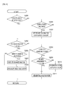
Fig. 3 is a flow chart illustrating a control flow of a machine tool control device as an embodiment of the present invention; -
Fig. 4 is a flow chart illustrating a control flow of a machine tool control device as an embodiment of the present invention; and -
Fig. 5 includes a graph illustrating chronological change of a thermal displacement amount, workpiece dimensions, and a correction value and a timing chart of switching analysis modes. - A machine
tool control device 100 as one embodiment of the present invention will now be described. As shown inFig. 1 , the machinetool control device 100 includes a sequentialanalysis control unit 110, an advanceanalysis control unit 120, a correctionamount calculation unit 130, a changeamount calculation unit 140, and amode switching unit 150, and controls a machine tool M. The machine tool M is supposed to be a machine tool that continuously machines a plurality of workpieces, such as an automatic lathe that machines a bar, and includes a main spindle M1, a main spindle Z-axis motor M2, a Z-axis ball screw M3, a working tool M4, a tool post M5, an X-axis ball screw M6, and a tool post X-axis motor M7. - On the basis of a pre-stored machining program, the machine
tool control device 100 controls rotation of the main spindle Z-axis motor M2 for moving the main spindle M1 along the Z-axis ball screw M3 in a Z-axis direction, and controls rotation of the tool post X-axis motor M7 for moving the tool post M5 along the X-axis ball screw M6 in an X-axis direction. This enables the machine tool M to machine a workpiece W. - When the machine tool M machines the workpiece W, heat is usually generated by the rotation of the motors and the friction of the ball screws, for example. The heat causes elongation of the ball screws, for example, and that leads to a machining error (thermal displacement). To address this problem, the machine
tool control device 100 is configured such that the correctionamount calculation unit 130 calculates a thermal displacement correction amount as a correction value for correcting the thermal displacement and the changeamount calculation unit 140 calculates a change amount of the correction value (correction amount). - As shown in
Fig. 2 , the correctionamount calculation unit 130 sequentially calculates a correction value at a certain interval regardless of machining cycles of the workpiece W. The correction value is stored in a memory such as a register (not shown). The correction value is calculated based on the temperature and amount of thermal displacement in the machine tool, for example. A method of calculating the correction value is well-known and the detailed description thereof is thus omitted. - As shown in
Fig. 3 , the changeamount calculation unit 140 determines whether a correction value is calculated by the correction amount calculation unit (step S110), obtains the correction value if it is calculated (step S102), and calculates a change amount on the basis of the obtained correction value (step S103). The change amount can be calculated by using the difference between successively calculated correction amounts or an average movement, for example. - The change
amount calculation unit 140 then determines whether the change amount is within a predetermined range of threshold (step S104), and sets an advance analysis flag if the change amount is within the predetermined range (step S105). If the change amount is not within the predetermined range in step S104, it is determined whether the advance analysis flag is set (step S106). If the advance analysis flag is not set, the process returns to the start. If the advance analysis flag is set, the advance analysis flag is reset and the process returns to the start. - Accordingly, the change amount of the correction value is sequentially calculated on the basis of the correction value, and the advance analysis flag is set or reset on the basis of the change amount. Because the correction value is output regardless of machining cycles of the workpiece W, the advance analysis flag is also set or reset regardless of machining cycles of the workpiece W.
- The machine
tool control device 100 has a sequential analysis mode and an advance analysis mode. In the sequential analysis mode, the sequential analysis control unit (sequential analysis control means) 110 reads and executes a machining program one line at a time and controls each of the motors. In the advance analysis mode, the advance analysis control unit (advance analysis control means) 120 preliminarily decodes the machining program in a lump, converts the program in a predetermined form, and executes the converted program to control each of the motors. The sequential analysis mode and the advance analysis mode are switched and alternately set by themode switching unit 150. The machinetool control device 100 controls machining of the workpiece W in either the sequential analysis mode or the advance analysis mode. - As shown in
Fig. 4 , themode switching unit 150 determines whether a sequential analysis continuation flag, which is set in step S210 0 and reset in step S207, is set (step S201). If the sequential analysis continuation flag is not set, themode switching unit 150 determines whether the advance analysis flag is set (step S202). - If the advance analysis flag is set, the
mode switching unit 150 determines whether the sequential analysis mode is set (step S203). If the sequential analysis mode is set, themode switching unit 150 makes the advanceanalysis control unit 120 execute advance analysis and perform calculation of the advance analysis (step S204), and sets the advance analysis mode (step S205). If the sequential analysis mode is not set in step S203, step S205 is directly carried out and the advance analysis mode continues without performing re-calculation of the advance analysis. - If the advance analysis flag is not set in step S202, it is determined whether the advance analysis mode is set (step S208). If the advance analysis mode is set, it is determined whether the advance analysis mode has been set for a certain period of time (step S209).
- If the advance analysis mode has been set for the certain period of time, the sequential analysis mode is set (step S211). If the advance analysis mode has not been set for the certain period of time, the sequential analysis continuation flag is set (step S21 0), and the sequential analysis mode is set in step S211. If the advance analysis mode is not set in step S208, the sequential analysis mode is set in step S211 and the sequential analysis mode continues.
- If the sequential analysis continuation flag is set in step S201, it is determined whether the sequential analysis mode has been set for a certain period of time (step S206). If the sequential analysis mode has been set for the certain period of time, the sequential analysis continuation flag for continuing the sequential analysis mode is reset (step S207), and step S202 is executed. If it is determined in step S206 that the sequential analysis mode has not been set for the certain period of time, step S211 is executed. The
mode switching unit 150 repeatedly executes steps S201 to S211 at the end of each machining cycle of the workpiece W until the machine tool M completes machining of the workpiece W. - On the basis of the above described operation of the
mode switching unit 150, the machinetool control device 100 sets the advance analysis mode when the advance analysis flag is set by the changeamount calculation unit 140 and sets the sequential analysis mode when the advance analysis flag is not set at the end of each machining cycle of the workpiece W. - If the advance analysis mode is switched to the sequential analysis mode within a predetermined certain period of time, however, the sequential analysis mode continues for a predetermined certain sequential analysis execution period regardless of the setting of the advance analysis flag. Steps S201, S206, and S207 constitute sequential analysis continuous activation means for continuously activating the sequential analysis mode for the sequential analysis execution period.
- When the machine
tool control device 100 is in the sequential analysis mode, the sequentialanalysis control unit 110 executes a machining program one line at a time while making correction on the basis of a correction value at the beginning of a machining cycle of the workpiece W (such as a correction value A inFig. 2 ). This enables to correct thermal displacement and the machine tool M can machine the workpiece W highly accurately. - When the machine
tool control device 100 is in the advance analysis mode, the machine tool M can machine the workpiece W faster than when the machinetool control device 100 is in the sequential analysis mode, due to the program converted by the advanceanalysis control unit 120. The thermal displacement is corrected and highly accurate machining of the workpiece W is maintained in the advance analysis mode because the advanceanalysis control unit 120 converts the machining program on the basis of the latest correction value whose change amount is within the range of threshold (such as a correction value F inFig. 2 ). The correction value used by the advanceanalysis control unit 120 for converting the machining program may be any value other than the above-described latest value, as long as the change amount of the correction value is within the range of threshold. For example, the correction value may be the first correction value whose change amount is within the range of threshold (such as a correction value C inFig. 2 ) or an average of correction values whose change amounts are within the range of threshold. - When the advance analysis mode continues, however, the machine
tool control device 100 continuously uses the program initially converted by the advanceanalysis control unit 120. Thus, as shown inFig. 5 , if the amount of the thermal displacement increases with respect to the correction value used by the advanceanalysis control unit 120 for converting the machining program and the change amount of a sequentially calculated correction value becomes out of the range of threshold, the accuracy of machining the workpiece W decreases and a machining error increases. - To address this issue, the calculation of a correction value by the correction
amount calculation unit 130, the calculation of the change amount by the changeamount calculation unit 140, and the setting/resetting of the advance analysis flag are continuously executed even after the advance analysis mode is set. Thus, as shown inFig 5(b) , the machinetool control device 100 reverts to the sequential analysis mode when the change amount of a correction value, which was once within the range of threshold, becomes out of the range of threshold even after the advance analysis mode is set. The machinetool control device 100 can thus increase the accuracy of machining the workpiece W in accordance with the thermal displacement amount under the sequential analysis mode that is based on the latest correction amount - This enables the machine tool M to maintain the highly accurate machining of the workpiece W. It is thus possible to increase the processing speed of machining the workpiece W by setting the machine
tool control device 100 to the advance analysis mode and executing advance analysis, and to keep the accuracy of machining the workpiece W by setting the machinetool control device 100 back to the sequential analysis mode as need arises, without measuring or calculating a saturated thermal displacement amount in advance. The range of threshold is thus set as a machining error range that is acceptable with respect to planned dimensions of a workpiece. - When the workpiece W is machined in the advance analysis mode, the processing speed increases by a certain percentage per machining cycle of the workpiece W in comparison with the sequential analysis mode. Thus, if a cycle time of one machining cycle in the sequential analysis mode is t and a percentage of increase per machining cycle is α%, then the processing time of the workpiece W can be reduce by α*t/100 per machining cycle. For example, if the processing speed increases 5% per machining cycle of the workpiece W in the advance analysis mode, then the reduction of processing time per machining cycle is 0.05t.
- On the other hand, when the workpiece W is machined in the advance analysis mode, the advance analysis needs to be executed by the advance
analysis control unit 120 before machining the workpiece W. A calculation time needed for executing the advance analysis, T, can be balanced out by machining the workpiece W in the advance analysis mode for T/(reduction of processing time) cycles. If the advance analysis mode continues for more than T/(reduction of processing time) cycles, or more than t*T/(reduction of processing time) = T/0.05, the whole machining time can be reduced. For example, if the reduction of processing time is 0.05t as described above, the whole machining time can be reduced by machining the workpiece W in the advance analysis mode for more than t*T/0.05t = T/0.05. - If the machine
tool control unit 100 switches from the advance analysis mode to the sequential analysis mode within t*T/(reduction of processing time) after switching from the sequential analysis mode to the advance analysis mode, however, the calculation time T that occurs when switching to the advance analysis mode cannot be balanced out. If the sequential analysis mode continues thereafter, the whole machining time will be rather longer. - It is guessed that the machine
tool control unit 100 switches from the advance analysis mode to the sequential analysis mode within t*T/(reduction of processing time) because thermal displacement is unstable. Thus, themode switching unit 150 sets the certain period of time used in step S209 as t*T/(reduction of processing time), such as T/0.05, and the sequential analysis continuous activation means activates the sequential analysis mode for the sequential analysis execution period, regardless of the setting (on/off) of the advance analysis flag, when the machinetool control unit 100 switches from the advance analysis mode to the sequential analysis mode within t*T/(reduction of processing time). - This prevents frequent switching between the sequential analysis mode and the advance analysis mode and restricts the increase in the machining time. The sequential analysis execution period may be any time period within which thermal displacement is expected to be stabilized, such as twice as long as t*T/(reduction of processing time).
-
- 100
- Machine tool control device
- 110
- Sequential analysis control unit
- 120
- Advance analysis control unit
- 130
- Correction amount calculation unit
- 140
- Change amount calculation unit
- 150
- Mode switching unit
- M
- Machine tool
- M1
- Main spindle
- M2
- Main spindle Z-axis motor
- M3
- Z-axis ball screw
- M4
- Working tool
- M5
- Tool post
- M6
- X-axis ball screw
- M7
- Tool post X-axis motor
- W
- Workpiece
Claims (4)
- A machine tool control device comprising: sequential analysis control means for reading and executing a machining program for machining a workpiece one line at a time; advance analysis control means for preliminarily decoding the machining program in a lump and converting and executing the machining program in a predetermined form; and correction amount calculation means for sequentially calculating a correction amount for executing the machining program, the machine tool control device being capable of executing the machining program on the basis of a correction amount calculated by the correction amount calculation means and controlling an operation of a machine tool, characterized in that the machine tool control device further comprises: change amount calculation means for sequentially calculating a change amount of the correction amount; and mode switching means for switching between the advance analysis control means and the sequential analysis control means, the mode switching means being configured for activating the advance analysis control means when the change amount is within a predetermined range and activating the sequential analysis control means when the change amount is not within the predetermined range, the advance analysis control means being configured for executing the conversion of the machining program on the basis of a correction amount whose change amount is within the predetermined range and not re-executing the conversion of the machining program while the advance analysis control means is in operation.
- The machine tool control device according to claim 1, characterized in that the correction amount calculation means calculates a thermal displacement correction amount in accordance with thermal displacement in the machine tool.
- The machine tool control device according to claim 1 or 2, characterized in that the mode switching means is configured for switching between the advance analysis control means and the sequential analysis control means at the beginning of each machining cycle.
- The machine tool control device according to any one of claims 1 to 3, characterized in that the mode switching means comprises sequential analysis continuous activation means for activating the sequential analysis control means for a predetermined sequential analysis executing period when switching from the advance analysis control means to the sequential analysis control means within a predetermined time period after switching from the sequential analysis control means to the advance analysis control means.
Applications Claiming Priority (2)
| Application Number | Priority Date | Filing Date | Title |
|---|---|---|---|
| JP2011164370A JP5749596B2 (en) | 2011-07-27 | 2011-07-27 | Machine tool controller |
| PCT/JP2012/067777 WO2013015124A1 (en) | 2011-07-27 | 2012-07-12 | Control device for machine tool |
Publications (2)
| Publication Number | Publication Date |
|---|---|
| EP2737973A1 true EP2737973A1 (en) | 2014-06-04 |
| EP2737973A4 EP2737973A4 (en) | 2016-04-27 |
Family
ID=47600976
Family Applications (1)
| Application Number | Title | Priority Date | Filing Date |
|---|---|---|---|
| EP12816899.4A Withdrawn EP2737973A4 (en) | 2011-07-27 | 2012-07-12 | Control device for machine tool |
Country Status (7)
| Country | Link |
|---|---|
| US (1) | US9360856B2 (en) |
| EP (1) | EP2737973A4 (en) |
| JP (1) | JP5749596B2 (en) |
| KR (1) | KR101528295B1 (en) |
| CN (1) | CN103930240B (en) |
| TW (1) | TWI574135B (en) |
| WO (1) | WO2013015124A1 (en) |
Cited By (1)
| Publication number | Priority date | Publication date | Assignee | Title |
|---|---|---|---|---|
| CN104122839A (en) * | 2014-07-11 | 2014-10-29 | 北京工业大学 | Method for solving machine tool machining errors caused by foundation deformation |
Families Citing this family (6)
| Publication number | Priority date | Publication date | Assignee | Title |
|---|---|---|---|---|
| WO2014038002A1 (en) * | 2012-09-04 | 2014-03-13 | 三菱電機株式会社 | Numerical control device |
| JP6107210B2 (en) * | 2013-02-20 | 2017-04-05 | 日本精工株式会社 | Thread part processing method and processing apparatus |
| JP5800884B2 (en) * | 2013-11-19 | 2015-10-28 | ファナック株式会社 | Chamfering machine tool and chamfering method |
| TWI554856B (en) * | 2015-10-30 | 2016-10-21 | 財團法人工業技術研究院 | Apparatus and method for transforming nc programs |
| JP6561003B2 (en) * | 2016-03-18 | 2019-08-14 | オークマ株式会社 | Machine tool thermal displacement correction method, machine tool |
| JP6743238B1 (en) * | 2019-04-23 | 2020-08-19 | Dmg森精機株式会社 | Variation amount estimating device and correction amount calculating device in machine tool |
Family Cites Families (18)
| Publication number | Priority date | Publication date | Assignee | Title |
|---|---|---|---|---|
| DE4203994A1 (en) | 1992-02-12 | 1993-08-19 | Hermle Berthold Maschf Ag | MACHINE TOOL WITH AN AUTOMATIC THERMAL EXPANSION COMPENSATION DEVICE |
| JPH0775937A (en) * | 1993-09-07 | 1995-03-20 | Sodick Co Ltd | Machine tool and control method thereof |
| JP3684718B2 (en) | 1996-11-11 | 2005-08-17 | ブラザー工業株式会社 | Machine tool controller |
| JP2000330617A (en) | 1999-05-17 | 2000-11-30 | Toshiba Mach Co Ltd | Numerical controller and feed control processing method for numerical controller |
| JP4718040B2 (en) | 2001-05-16 | 2011-07-06 | シチズンホールディングス株式会社 | Numerical control device, method of executing numerical control program, and program thereof |
| JP4443891B2 (en) * | 2003-10-23 | 2010-03-31 | 住友重機械工業株式会社 | Stage equipment |
| JP4299761B2 (en) * | 2004-10-22 | 2009-07-22 | ヤマザキマザック株式会社 | Thermal displacement correction method and thermal displacement correction apparatus for machine tool |
| DE102005008500B3 (en) * | 2005-02-24 | 2006-08-10 | Siemens Ag | Machine tool, production machine and robot controlling method, involves providing partial program with processing sets, and producing data set from sets`parameters, where certain parameters to be read by interpreter are registered in form |
| JP4760091B2 (en) * | 2005-03-30 | 2011-08-31 | ブラザー工業株式会社 | Machine tool and displacement correction method for machine tool |
| US7315765B1 (en) * | 2005-07-29 | 2008-01-01 | Advanced Micro Devices, Inc. | Automated control thread determination based upon post-process consideration |
| CN100401218C (en) * | 2005-12-13 | 2008-07-09 | 天津大学 | Open motion control card and control method for parallel equipment based on two-level DSP |
| CN1868666A (en) * | 2006-06-28 | 2006-11-29 | 四川长征机床集团有限公司 | Heat distortion compensation method of digial controlled machine tool main driving system |
| US9069345B2 (en) * | 2009-01-23 | 2015-06-30 | Mks Instruments, Inc. | Controlling a manufacturing process with a multivariate model |
| JP5202735B2 (en) * | 2009-06-03 | 2013-06-05 | 三菱電機株式会社 | Numerical controller |
| TWI409601B (en) * | 2009-11-06 | 2013-09-21 | Syntec Inc | Numerical control device and system of controlling corner motion and method of controlling the corner motion |
| CN101804581A (en) * | 2010-03-23 | 2010-08-18 | 四川普什宁江机床有限公司 | Implementation method of automatic compensation for thermal deformation of machine tool |
| US8845247B2 (en) * | 2011-06-28 | 2014-09-30 | Buffalo Machinery Company Limited | Thermal compensation system for a milling machine |
| JP5462296B2 (en) * | 2012-02-13 | 2014-04-02 | ファナック株式会社 | Machine tool warm-up operation control device |
-
2011
- 2011-07-27 JP JP2011164370A patent/JP5749596B2/en not_active Expired - Fee Related
-
2012
- 2012-07-12 US US14/131,766 patent/US9360856B2/en not_active Expired - Fee Related
- 2012-07-12 WO PCT/JP2012/067777 patent/WO2013015124A1/en not_active Ceased
- 2012-07-12 CN CN201280037243.1A patent/CN103930240B/en not_active Expired - Fee Related
- 2012-07-12 EP EP12816899.4A patent/EP2737973A4/en not_active Withdrawn
- 2012-07-12 KR KR1020147000656A patent/KR101528295B1/en not_active Expired - Fee Related
- 2012-07-24 TW TW101126601A patent/TWI574135B/en not_active IP Right Cessation
Cited By (2)
| Publication number | Priority date | Publication date | Assignee | Title |
|---|---|---|---|---|
| CN104122839A (en) * | 2014-07-11 | 2014-10-29 | 北京工业大学 | Method for solving machine tool machining errors caused by foundation deformation |
| CN104122839B (en) * | 2014-07-11 | 2017-01-25 | 北京工业大学 | Method for solving machine tool machining errors caused by foundation deformation |
Also Published As
| Publication number | Publication date |
|---|---|
| CN103930240A (en) | 2014-07-16 |
| JP2013027946A (en) | 2013-02-07 |
| KR101528295B1 (en) | 2015-06-15 |
| TW201314394A (en) | 2013-04-01 |
| JP5749596B2 (en) | 2015-07-15 |
| TWI574135B (en) | 2017-03-11 |
| US20140156056A1 (en) | 2014-06-05 |
| US9360856B2 (en) | 2016-06-07 |
| EP2737973A4 (en) | 2016-04-27 |
| WO2013015124A1 (en) | 2013-01-31 |
| CN103930240B (en) | 2016-03-02 |
| KR20140045975A (en) | 2014-04-17 |
Similar Documents
| Publication | Publication Date | Title |
|---|---|---|
| US9360856B2 (en) | Machine tool control device | |
| JP4917665B1 (en) | Thermal displacement correction method and thermal displacement correction apparatus for machine tool | |
| EP2071419B1 (en) | Numerical controller having control mode switching function | |
| CN103217927B (en) | The thermal displacement correction device of lathe | |
| JP6267041B2 (en) | Machine tool thermal displacement compensation device | |
| US10678222B2 (en) | Data collection device and computer readable medium | |
| JP4374045B2 (en) | Numerical control device with program restart function | |
| US9471058B2 (en) | Data acquisition device for acquiring cause of stoppage of drive axis and information relating thereto | |
| JP2005216135A (en) | Threading/tapping controller | |
| CN110096028B (en) | Reference temperature setting device, reference temperature setting method, and computer readable medium | |
| JP2012234445A (en) | Numerical controller having function of operation based on table format data | |
| CN100411792C (en) | Thread cutting control method and device thereof | |
| JP2005313280A (en) | Numerical control device | |
| JP4282631B2 (en) | Numerical control device that operates with tabular data | |
| US20190236823A1 (en) | Display unit and machine tool | |
| US20150362910A1 (en) | Numerical controller having function of superimposing superposition cycle synchronized with periodic operation cycle | |
| JP2004167549A (en) | Laser beam machining apparatus | |
| CN101340171A (en) | Stepper Motor Control Unit | |
| US20010013267A1 (en) | Machine tool and control method therefor | |
| US10012973B2 (en) | Numerical controller | |
| CN104865890B (en) | Carry out the numerical control device of the operating based on table formateed data | |
| JP2000099119A (en) | Correcting method for ball screw pitch error | |
| CN106970652B (en) | Motion controller | |
| WO1990010899A1 (en) | Numerical control device for transfer machine | |
| WO2024189813A1 (en) | Numerical control device and computer-readable storage medium |
Legal Events
| Date | Code | Title | Description |
|---|---|---|---|
| PUAI | Public reference made under article 153(3) epc to a published international application that has entered the european phase |
Free format text: ORIGINAL CODE: 0009012 |
|
| 17P | Request for examination filed |
Effective date: 20140117 |
|
| AK | Designated contracting states |
Kind code of ref document: A1 Designated state(s): AL AT BE BG CH CY CZ DE DK EE ES FI FR GB GR HR HU IE IS IT LI LT LU LV MC MK MT NL NO PL PT RO RS SE SI SK SM TR |
|
| DAX | Request for extension of the european patent (deleted) | ||
| RAP1 | Party data changed (applicant data changed or rights of an application transferred) |
Owner name: CITIZEN HOLDINGS CO., LTD. Owner name: CITIZEN MACHINERY CO., LTD. |
|
| RA4 | Supplementary search report drawn up and despatched (corrected) |
Effective date: 20160401 |
|
| RIC1 | Information provided on ipc code assigned before grant |
Ipc: G05B 19/4155 20060101ALI20160324BHEP Ipc: B23Q 15/18 20060101AFI20160324BHEP Ipc: G05B 19/404 20060101ALI20160324BHEP |
|
| RAP1 | Party data changed (applicant data changed or rights of an application transferred) |
Owner name: CITIZEN MACHINERY CO., LTD. Owner name: CITIZEN WATCH CO., LTD. |
|
| GRAP | Despatch of communication of intention to grant a patent |
Free format text: ORIGINAL CODE: EPIDOSNIGR1 |
|
| STAA | Information on the status of an ep patent application or granted ep patent |
Free format text: STATUS: GRANT OF PATENT IS INTENDED |
|
| INTG | Intention to grant announced |
Effective date: 20170512 |
|
| STAA | Information on the status of an ep patent application or granted ep patent |
Free format text: STATUS: THE APPLICATION IS DEEMED TO BE WITHDRAWN |
|
| 18D | Application deemed to be withdrawn |
Effective date: 20170923 |