EP2737882A1 - Urine absorption device - Google Patents
Urine absorption device Download PDFInfo
- Publication number
- EP2737882A1 EP2737882A1 EP12820606.7A EP12820606A EP2737882A1 EP 2737882 A1 EP2737882 A1 EP 2737882A1 EP 12820606 A EP12820606 A EP 12820606A EP 2737882 A1 EP2737882 A1 EP 2737882A1
- Authority
- EP
- European Patent Office
- Prior art keywords
- urine
- receptacle
- outlet port
- collecting container
- transverse direction
- Prior art date
- Legal status (The legal status is an assumption and is not a legal conclusion. Google has not performed a legal analysis and makes no representation as to the accuracy of the status listed.)
- Withdrawn
Links
Images




Classifications
-
- A—HUMAN NECESSITIES
- A61—MEDICAL OR VETERINARY SCIENCE; HYGIENE
- A61G—TRANSPORT, PERSONAL CONVEYANCES OR ACCOMMODATION SPECIALLY ADAPTED FOR PATIENTS OR DISABLED PERSONS; OPERATING TABLES OR CHAIRS; CHAIRS FOR DENTISTRY; FUNERAL DEVICES
- A61G9/00—Bed-pans, urinals or other sanitary devices for bed-ridden persons; Cleaning devices therefor, e.g. combined with toilet-urinals
- A61G9/006—Urinals
-
- A—HUMAN NECESSITIES
- A47—FURNITURE; DOMESTIC ARTICLES OR APPLIANCES; COFFEE MILLS; SPICE MILLS; SUCTION CLEANERS IN GENERAL
- A47K—SANITARY EQUIPMENT; ACCESSORIES THEREFOR, e.g. TOILET ACCESSORIES
- A47K11/00—Closets without flushing; Urinals without flushing; Chamber pots; Chairs with toilet conveniences or specially adapted for use with toilets
-
- A—HUMAN NECESSITIES
- A61—MEDICAL OR VETERINARY SCIENCE; HYGIENE
- A61F—FILTERS IMPLANTABLE INTO BLOOD VESSELS; PROSTHESES; DEVICES PROVIDING PATENCY TO, OR PREVENTING COLLAPSING OF, TUBULAR STRUCTURES OF THE BODY, e.g. STENTS; ORTHOPAEDIC, NURSING OR CONTRACEPTIVE DEVICES; FOMENTATION; TREATMENT OR PROTECTION OF EYES OR EARS; BANDAGES, DRESSINGS OR ABSORBENT PADS; FIRST-AID KITS
- A61F5/00—Orthopaedic methods or devices for non-surgical treatment of bones or joints; Nursing devices ; Anti-rape devices
- A61F5/44—Devices worn by the patient for reception of urine, faeces, catamenial or other discharge; Colostomy devices
- A61F5/451—Genital or anal receptacles
-
- A—HUMAN NECESSITIES
- A61—MEDICAL OR VETERINARY SCIENCE; HYGIENE
- A61F—FILTERS IMPLANTABLE INTO BLOOD VESSELS; PROSTHESES; DEVICES PROVIDING PATENCY TO, OR PREVENTING COLLAPSING OF, TUBULAR STRUCTURES OF THE BODY, e.g. STENTS; ORTHOPAEDIC, NURSING OR CONTRACEPTIVE DEVICES; FOMENTATION; TREATMENT OR PROTECTION OF EYES OR EARS; BANDAGES, DRESSINGS OR ABSORBENT PADS; FIRST-AID KITS
- A61F5/00—Orthopaedic methods or devices for non-surgical treatment of bones or joints; Nursing devices ; Anti-rape devices
- A61F5/44—Devices worn by the patient for reception of urine, faeces, catamenial or other discharge; Colostomy devices
- A61F5/451—Genital or anal receptacles
- A61F5/453—Genital or anal receptacles for collecting urine or other discharge from male member
Definitions
- the present invention relates to urine disposal devices each including a urine receptacle having a urine receiving space defined therein and external equipment at least including a vacuum pump adapted to suction such urine from the urine receiving space.
- a urine disposal device in the specification of the patent application No. 2011-011411 , includes a urine receptacle adapted to be put on a penis (hereinafter designated as genitalia), external equipment at least including a vacuum pump to suction urine from a receiving space and a connector serving to connect the urine disposal device to the external equipment.
- genitalia a urine receptacle adapted to be put on a penis
- external equipment at least including a vacuum pump to suction urine from a receiving space and a connector serving to connect the urine disposal device to the external equipment.
- the connector at least includes a first connector tube and a joint.
- the first connector tube has one end joined to the vacuum pump.
- the urine receptacle is disposed with a urine collecting container.
- the urine collecting container has an internal outlet port provided in an internal space of the container, an external outlet port (connecting region) provided on the outside of the internal space and a tubular member to put the internal outlet port and the external outlet port into a fluid-communication relationship.
- Another end of the first connector tube is connected to the external outlet port and whereby the urine receptacle is connected to the vacuum pump.
- the urine collecting container is arranged on the skin-contact surface of the urine receptacle wearer being in a supine posture and, when the wearer has evacuated the bowels (excrement), the end portion of the first connector tube will be soiled with the excrement. Thereafter, when the used urine receptacle is exchanged with the fresh one, the end portion of the first connector tube soiled with the excrement must be cleaned.
- the known urine disposal device has left behind a problem that it takes a lot of trouble to exchange the urine receptacle.
- an object of the present invention is to provide a urine disposal device improved so as to alleviate a possibility that the connector might be soiled with the wearer's excrement.
- Some embodiments of the present invention provide a urine disposal device having a longitudinal direction, a transverse direction and a thickness direction and including a urine receptacle and adapted to connect the urine receptacle through a connector to external equipment at least including a vacuum pump to suction urine from the urine receptacle.
- the present invention lies in that the urine receptacle has a first surface facing a wearer's skin, a second surface not facing the wearer's skin when the wearer is in a supine posture and a connecting region in which the connector is connected wherein the connecting region is arranged on the second surface.
- the present invention may at least include embodiments as described below.
- the connecting region of the urine receptacle is arranged on the second surface not facing the wearer's skin.
- the urine receptacle covers the distal end portion of the connector and the connecting region, whereby the distal end portion of the connector and the connecting region are unlikely to be soiled with the excrement.
- the connecting region should not come in contact with the wearer's body since the connecting region is arranged on the second surface. In this way, it is possible to alleviate a sense of discomfort felt by the wearer, even if the urine collecting container is formed of a thermoplastic synthetic resin.
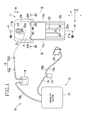
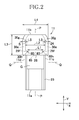
- Fig. 1 is the overall diagram schematically illustrating the urine disposal device according to the present invention and Fig. 2 is the plan view of the urine receptacle as seen from its lower side.
- X indicates a transverse direction
- Y indicates a longitudinal direction being orthogonal to the transverse direction X.
- P indicates an imaginary longitudinal center line bisecting a generally bag-shaped urine receptacle 11 in the transverse direction X
- Q indicates an imaginary transverse center line bisecting the urine receptacle 11 in the longitudinal direction Y.
- a urine disposal device 10 includes the urine receptacle 11, a connector 12, a urine tank 14 and a vacuum pump 15.
- the urine receptacle 11 is dimensioned so that a length dimension in the longitudinal direction Y is longer than a length dimension in the transverse direction X and disposed with a urine collecting container 13.
- the urine collecting container 13 of the urine receptacle 11 is connected to the urine tank 14 through the connector 12.
- the connector 12 is adapted also to connect the urine receptacle 11 to external equipment O as described later and includes a first connecting tube 12a and a joint 12b.
- the urine tank 14 is connected to the vacuum pump 15 through a second connecting tube 12b.
- a control unit 17 is connected to the vacuum pump 15 through an electric wire 16 and an electric connector 20 is attached to a distal end of electric wires 18a, 18b extending from the control unit 17.
- the vacuum pump 15 functions to suction urine from a urine receiving space S described later.
- the electric connector 20 has a first terminal (not shown) adapted for electrically connecting the electric wire 18a to a first electrode 51 arranged adjacent to an end 22a of a urine sensor 22 and a second terminal (not shown) adapted for electrically connecting the electric wire 18b to a second electrode 52 arranged adjacent to the end 22a of the urine sensor 22 so that such electric connection may be switched off as the occasion demands.
- the urine sensor 22 detects urine discharged into the urine receiving space S and this urine detection signal is inputted to the control unit 17.
- the control unit 17 activates an electric motor (not shown) disposed adjacent to the vacuum pump 15 to actuate this pump. Actuation of the vacuum pump 15 causes the amount of air within the urine tank 14 to be suctioned out from the urine tank 14. Urine having been retained within the urine receiving space S to be collected first is suctioned into the urine collecting container 13 and then transferred through the first connecting tube 12a into the urine tank 14 so as to be reserved therein.
- the constituents of the urine disposal device 10 except the urine receptacle 11 and the connector 12, such as the urine tank 14, the vacuum pump 15 as well as the motor thereof and the control unit 17 will be generically designated as the external equipment O.
- the urine receptacle 11 is electrically connected to the external equipment O so far as the present embodiment is concerned, it is not essential that the urine receptacle 11 is electrically connected to the external equipment O.
- the electric connector 20 with a small sender so that a receiver set in the control unit 17 may receive the signals transmitted from the sender and, in response to such signals, the control unit 17 may activate an electric motor of the vacuum pump 15.
- the urine receptacle 11 has the longitudinal direction Y, the transverse direction X being orthogonal to the longitudinal direction Y and a thickness direction Z being orthogonal to both the longitudinal direction Y and the transverse direction X (See Figs. 1 , 2 and 7 ), and includes a first end edge 11a and a second end edge 11b spaced apart from and facing each other in the longitudinal direction Y and lateral edges 11c, 11d spaced apart from and facing each other in the transverse direction X.
- the urine receptacle 11 further includes a urination range 24 and extension flaps 25 contiguously extending from the urination zone 24 in the longitudinal direction Y.
- the urination region 24 and the extension flaps 25 have the same length dimension so far as the transverse direction X is concerned.
- the urination region 24 has a length dimension in the longitudinal direction Y corresponding to about 1/3 of the urine receptacle 11 and the extension flaps 25 have a length dimension in the longitudinal direction Y corresponding to about 2/3 of the urine receptacle 11.
- the urination region 24 has an opening 28 extending in the transverse direction X along a boundary line between the urination region 24 and each of the extension flaps 25. The opening 28 opens into the urine receiving space S defined within the urination region 24.
- the urine receptacle 11 includes a laminated sheet structure 29 and a backsheet 30.
- the laminated sheet structure 29 includes two or more sheets approximately the same in shape as well as in size layered together and has a length dimension in the longitudinal direction Y larger than in the transverse direction X.
- the laminated sheet structure 29 has a first end edge 29a and a second end edge 29b extending in the transverse direction X and lateral edges 29c, 2 9d extending in the longitudinal direction Y between the both end edges 29a, 29b.
- the lateral edges 29c, 2 9d have rectilinear portions 29e between which the length dimension in the transverse direction X is kept constant and narrow portions 29f between which the length dimension in the transverse direction X is smaller than that between the rectilinearportions 29e.
- Apairof the narrow portions 2 9f are formed to face each other across the imaginary longitudinal center line Q and arranged adj acent to the opening 28 as illustrated in Figs. 1 and 2 .
- the respective narrow portions 29f are generally shaped in arcs. As will be described later in detail, a care person inserts the fingers into these narrow portions 29f, thereby to open the opening 28.
- These narrow portions 29f are formed, for example, by partially cutting out the laminated sheet structure 29.
- the backsheet 30 has a length dimension in the transverse direction X larger than any constituent sheet in the laminated sheet structure 29.
- the backsheet 30 has a first end edge 30a and a second end edge 30b extending in the transverse direction X and lateral edges 30c, 30d extending in the longitudinal direction Y between the end edges 30a, 30b.
- the backsheet 30 is layered on the laminated sheet structure 29 in the thickness direction orthogonal to both the transverse direction X and the longitudinal direction Y so as to extend beyond the first end edge 29a of the laminated sheet structure 29.
- the backsheet 30 is formed of a liquid-impermeable material.
- the backsheet 30 is formed of a liquid-impermeable SMS fibrous nonwoven fabric, a spunbond fibrous nonwoven fabric, a plastic sheet of polyethylene or a laminate thereof.
- a plastic film 30y and an SMS fibrous nonwoven fabric 30x are laminated together.
- the backsheet 30 has a first fold line 32 extending in the transverse direction X along the first end edge 2 9a of the laminated sheet structure 29 and a second fold line 33 extending in the transverse direction X at a level between the first fold line 32 and the second end edge 30b.
- the backsheet 30 has lateral edges 34 on the outside in the transverse direction X of the laminated sheet structure 29. Referring to Fig. 4 , an approximately semi-circular exposed hole 79 is formed through the backsheet 30.
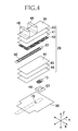
- the urine receptacle 11 includes the laminated sheet structure 29, the backsheet 30, the urine sensor 22, the urine collecting container 13, a hard-breathable sheet 46 and a pair of leakage-barrier sheets 48.
- the laminated sheet structure 29 includes, beginning at the top, a protection sheet 39, a liquid-permeable topsheet 40, a second sheet 41, an elastic rebound sheet 42, a cushion sheet 44, a diffusion sheet 45 and a suction backsheet 49.
- These sheets 39, 40, 41, 42, 44, 45, 49 are formed of thermoplastic synthetic resins as described later so as to have rectangular shapes approximately the same in shape as well as in size both in the transverse direction X and the longitudinal direction Y. Surfaces of these sheets 39, 40, 41, 42, 44, 45 and 49 to be contact with each other are distributed with a hot melt adhesive (not shown) at some interval and joined to each other through the hot melt adhesive.
- the protection sheet 39 serves to protect the topsheet 40 and is formed of a thermoplastic synthetic resin.
- the topsheet 40 is formed of a liquid-permeable fibrous nonwoven fabric made of a thermoplastic synthetic resin, for example, formed of an air-through nonwoven fabric having a mass per unit area in a range of about 20 to about 40 g/m 2 .
- the second sheet 41 is formed of a liquid-permeable fibrous nonwoven fabric made of a thermoplastic synthetic resin, for example, formed of an air-through nonwoven fabric having a mass per unit area in a range of about 15 to about 25 g/m 2 .
- the elastic rebound sheet 42 is formed in a net-like fashion from a thermoplastic synthetic resin having an elastically rebounding property and has a liquid-permeable property since it is formed in the net-like fashion.
- the elastic rebound sheet 42 is formed of, for example, an ethylene-vinyl acetate sheet having a thickness in a range of about 0.5 to about 1.0 mm.
- the elastic rebound sheet 42 has an appropriate elastically rebounding force to tighten up around the wearer's genitalia inserted through the opening 28 into the urination region 22 and to prevent the genitalia from being displaced and to prevent urine from leaking out through the opening 28.
- the elastic rebound sheet 42 is not provided and the second sheet 41 is left in contact with the urine sensor 22, a portion of urine might be left behind absorbed by the second sheet 41 to keep the second sheet 41 in wet conditions even after a process of urine suction has been finished.
- the urine sensor 22 might erroneously detect urination.
- the elastic rebound sheet 42 is interposed between the second sheet 41 and the urine sensor 22 for the urine receptacle according to the present embodiment, whereby it is assured to prevent such erroneous detection.
- the elastic rebound sheet 42 is preferably secured to the cushion sheet 44 through partially distributed adhesive to the cushion sheet 44 to assure the liquid-permeability of the cushion sheet 44.
- the cushion sheet 44 is formed of a liquid-permeable nonwoven fabric sheet such as a thermal-bond nonwoven fabric sheet or an SMS nonwoven fabric sheet formed from a thermoplastic synthetic resin.
- the cushion sheet 44 has, for example, a mass per unit area in a range of about 20 to about 30 g/m 2 .
- the cushion sheet 44 functions to prevent a portion of urine which might be present in the diffusion sheet 45, the suction backsheet 49 and the hard-breathable sheet 46 from flowing toward the electrodes 51, 52.
- the diffusion sheet 45 is formed primarily from rayon fibers formed of a thermoplastic synthetic resin and hydrophilic fibers formed from a thermoplastic synthetic resin is mixed therewith to assure a liquid-permeability.
- the diffusion sheet 45 is used for the purpose of, as soon as urine is discharged, diffusing such urine in the transverse direction X as well as in the longitudinal direction Y, thereby rendering the suction backsheet 49 in wet conditions over a wide range.
- an internal space 64 of the urine collecting container 13 creates a negative pressure which, in turn, facilitates urine to be suctioned into the internal space 64 of the urine collecting container 13.
- the suction backsheet 49 is formed of a thermoplastic synthetic resin.
- the suction backsheet 49 has a mass per unit area in a range of about 70 to about 80 g/m 2 and, as material thereof, an airlaid fibrous nonwoven fabric maybe used.
- the suction backsheet 49 has the function and the property similar to the hard-breathable sheet 46 and may be formed of a similar material.
- the urine sensor 22 includes an insulating base sheet 50 formed of an approximately rectangular plastic film, the first electrode 51 and the second electrode 52 printed on the upper surface of the insulating base sheet 50 with an electrically conductive material such as electrically conductive ink or electrically conductive paint.
- the insulating base sheet 50 may be formed of, for example, a polyester film having a dimension in the thickness direction Z in a range of about 50 to about 100 ⁇ m.
- the electrodes 51, 52 are printed with ink containing artificial graphite such as carbon black in a range of about 3 to about 7 % by mass or carbon graphite in a range of about 10 to about 30 % by mass to make these electrodes 51, 52 electrically conductive.
- the insulating base sheet 50 is formed in a central region with a longitudinally long rectangular opening 53.
- the first and second electrodes 51, 52 are spaced by this opening 53 from each other so as to face each other and extending in the longitudinal direction Y.
- the respective electrodes 51, 52 have a plurality of urine detecting regions 54 exposed from the insulating base sheet 50.
- voltage is applied between the electrodes 51, 52 and urination is detected on the basis of a current differential measured in ordinary state and in a state in which urine has been discharged into the urine receiving space S of the urine receptacle 11.
- the urine collecting container 13 may be formed of, for example, a flexibly elastic and liquid-impermeable thermoplastic synthetic resin such as soft polyethylene or silicon rubber.
- the urine collecting container 13 has a flexibility allowing the container to be curved in the longitudinal direction Y and in the transverse direction X but has a stiffness enough to withstand a remarkable deformation owing to a negative pressure generated when the vacuum pump suctions urine.
- the urine collecting container 13 includes a bottom 60, a peripheral wall 61 rising from the bottom 60, an upper opening 62 surrounded by the peripheral wall 61 and a flange 63 extending outward from a top edge of the peripheral wall 61.
- the internal space 64 is defined by the suction backsheet 49 arranged so as to cover the bottom 60, the peripheral wall 61 and the upper opening 62.
- the urine collecting container 13 is disposed with a tubular member 65 extending in the longitudinal direction Y across an approximately central region.
- the tubular member 65 has an internal outlet port 65a arranged within the internal space 64 of the urine collecting container 13 and an external output 65b arranged at the outside of the internal space 64 so that the internal outlet port 65a and the external outlet port 65b may be in a fluid-communication relationship.
- the first connecting tube 12a is attached through the joint 12c (See Fig. 1 ).
- the external outlet port 65b of the urine connecting container 13 functions as a joining section.
- the urine collecting container 13 evacuates urine within the internal space through the internal outlet port 65a of the tubular member 65 in the urine evacuation direction A to the external outlet port 65b until urine within the internal space 64 becomes empty.
- a plurality of convexities projecting from the bottom is formedonbothsides in the transverse direction X of the tubular member 65.
- a plurality of convexities 67 projecting towards the internal outlet port 65a is formed on a portion of the peripheral wall 61 facing the internal outlet port 65a.
- the urine collecting container 13 is arranged in the urine receptacle 11 in such a manner that the urine evacuation direction A extending from the internal outlet port 65a to the external outlet port 65b is oriented toward the opening 28.
- the internal space 64 of the urine collecting container 13 has a length dimension in the longitudinal direction Y which is smaller than 1/2 of a length dimension in the longitudinal direction Y of the urination region 24.
- the urine collecting container 13 is arranged adjacent to the second end edge 11b of the urine receptacle 1 so that the internal space 64 of the urine collecting container 13 is positioned in a lower half in the longitudinal direction Y of the urination region 24.
- Fig. 8 is a sectional view illustrating the urine receptacle 11 put on the wearer.
- the urine receptacle 11 In a state that the urine receptacle 11 is put on the wearer in the supine posture, the urine receptacle 11 has a first surface G facing the wearer's skin and a second surface F not facing the wearer's skin.
- the urine collecting container 13 is arranged on the second surface of the urine receptacle 11.
- Fig. 9 is a diagram illustrating an arrangement of the urine collecting container 13.
- High stiffness regions 80 as described in more detail later are paired so as to be symmetric about the imaginary longitudinal center line Q.
- Each of the high stiffness regions 80 is formed in a circular shape and has a center.
- the urine collecting container 13 is illustrated in Fig. 9 so that the internal space 64 thereof may be exposed.
- the urine collecting container 13 is arranged in the urine receptacle 11 so that the internal space 64 may be positioned in this overlapping region 90.
- the internal space 64 of the urine collecting container 13 is arranged within the overlapping region 90 defined so that an angle ⁇ 1 formed between the vertical line M3 passing through the center of the high stiffness region 80 on one side in the transverse direction X is 45° or less and an angle ⁇ 2 formed between the vertical line M4 passing through the center of the high stiffness region 80 on the other side in the transverse direction X and the second imaginary line M2 is 45° or less.
- the urine collecting container 13 is arranged in the illustrated embodiment so that the upper side of the internal space 64 may be tangent to the imaginary lines M1, M2 extending at angles ⁇ 1, ⁇ 2 of about 25°.
- the hard-breathable sheet 46 is formed at a center thereof with a hole 57 adapted to be aligned with the upper opening 62 of the urine collecting container 13.
- the hard-breathable sheet 46 is joined to the urine collecting container 13 through adhesive distributed to the flange 63.
- the hard-breathable sheet 46 is liquid-permeable but approximately or absolutely hard-breathable and formed from a thermoplastic synthetic resin.
- As material for the hard-breathable sheet 46 for example, an SMS nonwoven fabric without any treatment or treated to become hydrophilic with use of surface acting agent may be used.
- a breathability of the hard-breathable sheet 46 is preferably in a range of 0 to 100 cc/cm 2 /sec in wet conditions and in a range of 20 to 200 cc/cm 2 /sec.
- the leakage-barrier sheet 48 is formed from a laminate of two or more appropriately rectangular sheets formed from a thermoplastic synthetic resin.
- the leakage-barrier sheet 48 may be formed of 4 to 8 air-through nonwoven fabric sheets having a mass per unit area in a range of about 30 to about 40 g/m 2 laminated in the thickness direction Z.
- the leakage-barrier sheet 48 is arranged along the periphery of the opening 28.
- predetermined portions are cut away from the laminated sheet structure 29 illustrated in Fig. 10 (a) .
- the cutting step along the lateral edges 29c, 29d extending in the longitudinal direction Y between the end edges 29a, 29b, there are the rectilinear portions 29e and the narrow portions 2 9f having a length dimension smaller than that of the rectilinear portions 29e.
- the distal end portion 2 9g On the side of the first end edge 29a, there is a distal end portion 2 9g having a length dimension in the transverse direction X smaller than that of the rectilinear portions 29e.
- the narrow portions 29f are arranged adjacent to the opening 28 as will be described later (See Fig. 2 ).
- the narrow portions 29f are arrangements into which the wearer's or the care person's fingers will be inserted to open the opening 28.
- Differential dimensions in the thickness direction between the laminated sheet structure 29 including seven sheets 39, 40, 41, 42, 44, 45, 49 and the backsheet 30 enables the wearer or the care person to recognize these narrow portions 29f by tactual sense. It is also possible for the wearer or the care person to recognize visually the narrow portions 29f so long as a total light transmittance of the backsheet 30 is in a range of about 30 to about 70 %.
- the backsheet 30 having the total light transmittance of about 40 % is used.
- the urine collecting container 13 is arranged on the backsheet 30 so that the external outlet port 65b of the urine collecting container 13 may be exposed through an exposing hole 79 and, as illustrated in Fig. 10 (b) , the urine collecting container 13 is attached to the backsheet 30 with the hot melt adhesive distributed to the backsheet 30 through the hard-breathable sheet 46. Then, all over the upper surface of the backsheet 30 is formed with adhesive regions 30e with the use of adhesive such as hot melt adhesive.
- the backsheet 30 is joined to the laminated sheet structure 29 through the adhesive regions 30e.
- a pair of the leakage-barrier sheets 48 are attached to the upper surface of the protection sheet 39.
- the lower side leakage-barrier sheet 48 is arranged adjacent to the first end edge 29a of the laminated sheet structure 29 and the upper side leakage-barrier sheet 48 is arranged adjacent to the second end edge 30b of the backsheet (30).
- the backsheet 30 is folded along the first fold line 32 so as to cover the lower side leakage-barrier sheet 48 and, as illustrated in Fig. 11 (a) , the portions of the backsheet 30 facing each other are joined together.
- the lower end of the backsheet 30 defines a third end edge 30f and the second fold line 33 coincides with a line bisecting the second end edge 30b and the third end edge 30f.
- the laminated sheet structure 29 and the backsheet 30 are folded along the second fold line 33 of the backsheet 30. More specifically, the laminated sheet structure 29 and the backsheet 30 are folded so that the protection sheet 39 may face itself and be put in contact with itself, whereby the third end edge 30f and the second end edge 30b of the backsheet 30 are put in coincidence with each other as illustrated in Fig. 11 (b) .
- the lateral edges 30c, 30d of the backsheet 30 are joined to each other to form joined lateral edge portions 30g on both sides in the transverse direction X and the opening 28 is formed in the thickness direction Z between the third end edge 30f and the second end edge 30b. In this way, the urine receiving space S in fluid communication with this opening 28 is formed within the urination region 24.
- the second fold line 33 defines the second end edge 11b of the urine receptacle 11.
- the sheets 39, 40, 41, 42, 44, 45 and 49 are heat sealed together in the thickness direction to form the high stiffness regions 80, thereby obtaining the urine receptacle 11 as illustrated in Fig. 11 (c) .
- each of the high stiffness regions 80 includes the thermoplastic synthetic resin sheets 39, 40, 41, 42, 44, 45 and 49 integrally heat sealed in the thickness direction Z so as to be continuous from the uppermost surface to the bottom surface in the thickness direction Z of the urine receptacle 11.
- the sheets 39, 40, 41, 42, 44, 45 and 49 are integrally sealed together to form the high stiffness regions 80 and necessarily stiffness higher than that in the other regions is assured by the high stiffness regions 80.
- the high stiffness regions 80 are formed so as to be on an imaginary shortest line 85 indicating the smallest length dimension in the transverse direction X of the laminated sheet structure 29 defined between a pair of the narrow portions 29f.
- Each of the high stiffness regions 80 may be formed as a circle having a diameter of 4 mm so as not to be put in contact with the narrow portion 29f.
- the adhesive regions 30e are formed of the adhesive distributed over the whole area on the upper surface of the backsheet 30 and exist also adjacent to the respective narrow portions 29f.
- the backsheet 30 is joined to itself adjacent to the respective narrow portions 29f through the adhesive regions 30e and joined lateral edge portions 30g extending in the longitudinal direction Y are formed on both sides in the transverse direction X of the urination region 24.
- the respective joined lateral edge portions 30g have extensions extending in the longitudinal direction Y closer to the opening 28 than to the high stiffness regions 80.
- a distance dimension L1 between a pair of the high stiffness regions 80 in the transverse direction X is shorter than a length dimension L2 in the transverse direction X of the opening 28 (See Fig. 2 ).
- the wearer's thumb is inserted into one of the narrow portions 29f and the wearer's first finger into the other narrow portion 29f.
- the thumb and first finger may be moved closer to each other to assure that the mid portions in the transverse direction X of the respective sheets 39,40, 41, 42, 44, 45 and 49 having a relatively high bending moment are folded and the opening 28 is smoothly opened.
- the forefront of the genitalia may be inserted into the opening 28 and further inserted toward the back of the urination region 24.
- the distance dimension L1 (See Fig. 2 ) in the transverse direction X between a pair of the high stiffness regions 80 is shorter than the length dimension L2 in the transverse direction X of the opening 28 and the high stiffness regions 80 are arranged rather within the urine receiving space S with respect to the opening 28. Consequently, the high stiffness regions 80 function as guide means for the forefront of the genitalia.
- the thumb and the first finger may be disengaged from the urine receptacle 11. Thereupon, the opening 28 is closed under the elastic rebounding force of the elastic rebound sheet 42. In this manner, as illustrated in Fig. 8 , it is possible to put the urine receptacle 11 on the genitalia R without touching the genitalia R with the wearer's hand.
- the high stiffness regions 80 are arranged closer to the imaginary longitudinal center line Q than the joined lateral edge portions 30g are. Consequently, pubic hair should not be caught by the adhesive regions 30e during insertion of the genitalia R.
- a length dimension L3 in the longitudinal direction Y of the urination region 24 is preferably in a range of 50 to 180 mm and, more preferably, in a range of 80 to 130 mm.
- the urination region 24 is the region adapted to receive the genitalia R inserted thereinto and to receive urine.
- the length dimension L3 in the longitudinal direction Y of the urination region 24 is relatively long, if the dimension L3 is excessively long, the lower end of the urine receptacle might come in contact with a wheel chair on the assumption that the wearer is in the wheel chair when he urinates. In contrast, if the dimension is excessively short, it maybe difficult to stably hold the genitalia within the urine receptacle. From this viewpoint, preferably an average length value of genitalia of Japanese men is calculated and the dimension L3 is determined in consideration of the calculated average value.
- the distance dimension L1 in the transverse direction X between a pair of the high stiffness regions 80 is a factor substantially specifying the genitalia R which can be properly inserted into the urine receptacle 11.
- the distance dimension L1 of 50 mm or more is sufficient to assure the desired function.
- the distance dimension L1 is preferably 75 mm or more. If the distance dimension L1 is excessively large, the elastically rebounding force of the elastic rebound sheet 42 might be insufficient to close the opening 28 and a portion of urine discharged into the urine receptacle might leak out through the opening.
- the distance dimension L1 of 130 mm or more is inappropriate. From these viewpoints, the distance dimension L1 is preferably in a range of 50 to 130 mm and more preferably in a range of 75 to 130 mm.
- the length dimension L2 in the transverse direction X of the urination region 24 is preferably in a range of about 60 to about 170 mm and more preferably in a range of about 85 to about 140 mm.
- the length dimension L2 in the transverse direction X of the urination region 24 it will be preferable to determine the length dimension L2 in the transverse direction X of the urination region 24 to be relatively large.
- the length dimension L2 is excessively large, the lateral portions of the urine receptacle 11 might be put in contact with the wearer's inner thighs.
- the length dimension L2 is excessively small, it will be difficult to hold the genitalia R stably.
- the length dimension L2 is preferably within the range as described above.
- the length dimension L4 in the transverse direction X of the urine receptacle 11 is a sum of the length dimension L2 in the transverse direction X of the urination region 24 and a length dimension two times the total length dimension L5 in the transverse direction X of a pair of the adhesive regions 30e of the backsheet 30.
- the external outlet port (connecting region) 65b of the urine receptacle 11 is arranged on the second surface F not facing the wearer's skin.
- the skin-contact surface of the urine receptacle 11 covers the first connecting tube 12a and the external outlet port 65b, whereby the distal end portion of the first connecting tube 12a and the external outlet port 65b are unlikely to be soiled with the excrement.
- the external outlet port 65b is unlikely to come in contact with the wearer's body since the external outlet port 65b is arranged on the second surface F. In this way, it is possible to alleviate a sense of discomfort felt by the wearer even if the urine collecting container 13 is formed of a thermoplastic synthetic resin.
- the urine collecting container 13 is arranged so that the internal space 64 may be arranged within the overlapping region 90 and the internal space 64 of the urine collecting container 13 is arranged within the overlapping region 90 defined so that an angle ⁇ 1 formed between the vertical line M3 passing through the center of the high stiffness region 80 on one side in the transverse direction X is 45° or less and an angle ⁇ 2 formed between the vertical line M4 passing through the center of the high stiffness region 80 on the other side in the transverse direction X and the second imaginary line M2 is 45° or less.
- Such arrangement is effective to prevent urine from leaking out through the opening 28 even when the wearer of the urine receptacle 11 is in a lying posture. Furthermore, the urine collecting container 13 is arranged so that the internal space 64 occupies a lower half of the urination region 24 and such arrangement assures that the discharged urine is reliably suctioned.
- the urine collecting container 13 is arranged in the urine receptacle 11 in such a manner that the urine evacuation direction A is oriented toward the opening 28.
- Such arrangement of the urine collecting container 13 makes it possible to arrange the internal outlet port 65 adjacent to the second end edge 11b of the urine receptacle 11, whereby urine is unlikely to remain in the urine receiving space S.
- the high stiffness regions 80 are locally formed as a portion of the periphery 28a of the opening 28 in the course of heat sealing a plurality of sheets 39, 40, 41, 42, 44, 45 and 49 and, more specifically, these high stiffness regions 80 are formed only on the respective lateral edges 30c, 30d in the transverse direction X of the sheets 39, 40, 41, 42, 44, 45 and 49. Consequently, the stiffness in the middle portions in the transverse direction X of these sheets is relatively low and the sheets 39, 40, 41, 42, 44, 45 and 46 are easily bent. In this manner, it is possible to provide the urine receptacle 11 of which the opening 28 may be smoothly opened.
- Urine discharged in the urination region 24 of the urine receptacle 11 is temporarily retained within the urine receiving space S defined within the urine receptacle 11.
- the amount of urine temporarily retained within the urine receiving space S permeates the topsheet 40, the second sheet 41 and the elastic rebound sheet 42 and come in contact with the urine sensor 22.
- the urine detection regions 54 detect the presence of urine.
- the control unit 17 Based on detection by the urine sensor 22, the control unit 17 actuates the vacuum pump 15. In response of actuation of the vacuum pump 15, the urine tank 14 enters a vacuum state and urine which has been retained within the internal space 64 of the urine collecting container 13 is suctioned through the first connecting tube 12a into the urine tank 14 and the urine receiving space S is evacuated. When the urine sensor 22 becomes unable to detect any amount of urine, the control unit 17 ceases to drive the vacuum pump 15 on the basis of non-detection by the urine sensor 22.
- the kinds of material for the constituent members of the urine receptacle 11 according to the present invention are not limited to those described in this specification but the other various types of material widely used in the relevant technical field may be used without limitation.
- the terms "first”, “second” and “third” used in the specification and Claims of the present invention are used merely to distinguish similar elements or similar positions.
- the laminated sheet structure 29 it is not essential to use all of the sheets 39, 40, 41, 42, 44, 45 and 49 but it is possible for any purpose to omit one or more from these sheets 39, 40, 41, 42, 44, 45 and 49. It is also possible to add any other kinds of sheets to these sheets as necessary.
- the urine receptacle 11 may be assembled by following other steps of assembling different from the steps of assembling as has been described above.
- the sheets including also the leakage-barrier sheets 48 may be heat sealed together to improve stiffness of the high stiffness regions 80, whereby the opening 28 may be more smoothly opened.
- stiffness regions 80 have been described to have the circular shapes, the shape of the high stiffness regions 80 may be arbitrarily selected and, for example, the stiffness regions 80 may have polygonal shapes.
- the urine collecting container 113 is arranged within the urine receptacle 111 so that the urine evacuation direction A from the internal outlet port 65a to the external outlet port 65b is not oriented to the opening 28 but reversely oriented.
- the urine collecting container 113 is arranged on the second surface F of the urine receptacle 111 for the wearer in a supine posture.
- the urine collecting container 113 is arranged within the urine receptacle so that the urine evacuation direction A may be not oriented toward the opening but reversely oriented and consequently it is possible to arrange the external outlet port 65b functioning also as the connecting region adj acent to the second end edge 11b of the urine receptacle 111, thereby facilitating the connector 12 to be connected with the external outlet port 65b.
Landscapes
- Health & Medical Sciences (AREA)
- Public Health (AREA)
- Veterinary Medicine (AREA)
- Epidemiology (AREA)
- General Health & Medical Sciences (AREA)
- Animal Behavior & Ethology (AREA)
- Life Sciences & Earth Sciences (AREA)
- Vascular Medicine (AREA)
- Heart & Thoracic Surgery (AREA)
- Biomedical Technology (AREA)
- Engineering & Computer Science (AREA)
- Nursing (AREA)
- Orthopedic Medicine & Surgery (AREA)
- Reproductive Health (AREA)
- Orthopedics, Nursing, And Contraception (AREA)
- External Artificial Organs (AREA)
- Absorbent Articles And Supports Therefor (AREA)
Abstract
Description
- The present invention relates to urine disposal devices each including a urine receptacle having a urine receiving space defined therein and external equipment at least including a vacuum pump adapted to suction such urine from the urine receiving space.
- In the specification of the patent application No.
2011-011411 , a urine disposal device is disclosed by the applicant of the present application. This urine disposal device includes a urine receptacle adapted to be put on a penis (hereinafter designated as genitalia), external equipment at least including a vacuum pump to suction urine from a receiving space and a connector serving to connect the urine disposal device to the external equipment. - In this urine disposal device, the connector at least includes a first connector tube and a joint. The first connector tube has one end joined to the vacuum pump.
- The urine receptacle is disposed with a urine collecting container. The urine collecting container has an internal outlet port provided in an internal space of the container, an external outlet port (connecting region) provided on the outside of the internal space and a tubular member to put the internal outlet port and the external outlet port into a fluid-communication relationship.
- Another end of the first connector tube is connected to the external outlet port and whereby the urine receptacle is connected to the vacuum pump.
- {PTL 1}: Specification of Patent Application No.
2011-011411 {Summary} - Wearers of such type of urine receptacle are often the aged and/or severely disabled persons and many of these persons spend most of the day on their beds. Furthermore, these persons spend most of the time on the bed in a supine posture or in a lying posture.
- In this known urine disposal device, the urine collecting container is arranged on the skin-contact surface of the urine receptacle wearer being in a supine posture and, when the wearer has evacuated the bowels (excrement), the end portion of the first connector tube will be soiled with the excrement. Thereafter, when the used urine receptacle is exchanged with the fresh one, the end portion of the first connector tube soiled with the excrement must be cleaned. Thus the known urine disposal device has left behind a problem that it takes a lot of trouble to exchange the urine receptacle.
- In view of this, an object of the present invention is to provide a urine disposal device improved so as to alleviate a possibility that the connector might be soiled with the wearer's excrement.
- Some embodiments of the present invention provide a urine disposal device having a longitudinal direction, a transverse direction and a thickness direction and including a urine receptacle and adapted to connect the urine receptacle through a connector to external equipment at least including a vacuum pump to suction urine from the urine receptacle.
- The present invention lies in that the urine receptacle has a first surface facing a wearer's skin, a second surface not facing the wearer's skin when the wearer is in a supine posture and a connecting region in which the connector is connected wherein the connecting region is arranged on the second surface.
- The present invention may at least include embodiments as described below.
- (1) The urine receptacle is disposed with a urine collecting container having an internal space. The urine collecting container includes an internal outlet port arranged within the internal space and an external outlet port arranged on the outside of the internal space and a tubular member adapted to put the internal outlet port and the external outlet port in a fluid-communication relationship wherein the external outlet port functions also as a connecting region.
- (2) The urine receptacle has an opening extending in the transverse direction. The urine collecting container is arranged so that a urine evacuation direction from the internal outlet port to the external outlet port may be oriented oppositely to the opening.
- (3) The urine receptacle has an opening extending in the transverse direction. The urine collecting container is arranged so that the urine evacuation direction from the internal outlet port to the external outlet port may be oriented towards the opening.
- (4) The urine receptacle is formed from a plurality of sheets made of a thermoplastic synthetic resin in a bag-like shape defining therein a urine receiving space in fluid-communication with the opening. High stiffness regions are formed in the course of heat sealing a plurality of sheets but the high stiffness regions are formed only on lateral edges of these sheets as a portion of the opening's periphery.
- (5) The respective high stiffness regions have centers. The urine collecting container is arranged so that the internal space may be positioned within an overlapping region in which a region defined under a first imaginary line extending so as to pass through the center of one of two high stiffness regions spaced apart from each other in the transverse direction and to be tangent to the internal space on the upper side of the urine collecting container and a region defined under a second imaginary line extending so as to pass through the center of the other high stiffness region and to be tangent to the internal space on the upper side of the urine collecting container overlap each other.
- In the urine disposal device according to the present invention put on the wearer in a supine posture, the connecting region of the urine receptacle is arranged on the second surface not facing the wearer's skin. In consequence, when the wearer discharges excrement, the urine receptacle covers the distal end portion of the connector and the connecting region, whereby the distal end portion of the connector and the connecting region are unlikely to be soiled with the excrement. In addition, the connecting region should not come in contact with the wearer's body since the connecting region is arranged on the second surface. In this way, it is possible to alleviate a sense of discomfort felt by the wearer, even if the urine collecting container is formed of a thermoplastic synthetic resin.
-
- {
Fig. 1} Fig. 1 is an overall diagram schematically illustrating a urine disposal device according to the present invention, inclusive of a plan view as seen from the upper side of a urine receptacle also according to the present invention. - {
Fig. 2} Fig. 2 is a plan view of the urine receptacle as seen from its lower side. - {
Fig. 3} Fig. 3 is a plan view of a laminated sheet and a backsheet. - {
Fig. 4} Fig. 4 is an exploded perspective view of the urine receptacle. - {
Fig. 5} Fig. 5 is a plan view of a urine sensor as seen from its upper side. - {
Fig. 6} Fig. 6 is a perspective view of a urine collecting container. - {
Fig. 7} Fig. 7 is a sectional view taken along line VII-VII inFig. 1 . - {
Fig. 8} Fig. 8 is a view similar toFig. 7 , illustrating the urine receptacle put on a wearer's genitalia. - {
Fig. 9} Fig. 9 is a diagram illustrating a position of a urine collecting container relative to the urine receptacle. - {
Fig.10} Fig. 10 (a) throughFig. 10 (c) are diagrams illustrating the steps of assembling the urine receptacle. - {
Fig.11} Fig. 11 (a) throughFig. 11 (c) are diagrams illustrating the steps of assembling the urine receptacle. - {
Fig. 12} Fig. 12 is a sectional view taken along line XII-XII inFig. 1 . - {
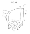
Fig. 13} Fig. 13 is a diagram illustrating the urine receptacle with an opening in an opened state when the urine receptacle is put on the wearer's genitalia. - {
Fig. 14} Fig. 14 is a partially scale-enlarged view of the urine receptacle according to another embodiment of the present invention. -
Fig. 1 is the overall diagram schematically illustrating the urine disposal device according to the present invention andFig. 2 is the plan view of the urine receptacle as seen from its lower side. Referring toFigs. 1 and2 , X indicates a transverse direction and Y indicates a longitudinal direction being orthogonal to the transverse direction X. Referring also toFigs. 1 and2 , P indicates an imaginary longitudinal center line bisecting a generally bag-shaped urine receptacle 11 in the transverse direction X and Q indicates an imaginary transverse center line bisecting theurine receptacle 11 in the longitudinal direction Y. - As illustrated in
Fig. 1 , aurine disposal device 10 includes theurine receptacle 11, aconnector 12, aurine tank 14 and avacuum pump 15. - The
urine receptacle 11 is dimensioned so that a length dimension in the longitudinal direction Y is longer than a length dimension in the transverse direction X and disposed with aurine collecting container 13. Theurine collecting container 13 of theurine receptacle 11 is connected to theurine tank 14 through theconnector 12. Theconnector 12 is adapted also to connect theurine receptacle 11 to external equipment O as described later and includes a first connectingtube 12a and ajoint 12b. Theurine tank 14 is connected to thevacuum pump 15 through a second connectingtube 12b. - A
control unit 17 is connected to thevacuum pump 15 through anelectric wire 16 and anelectric connector 20 is attached to a distal end ofelectric wires control unit 17. Thevacuum pump 15 functions to suction urine from a urine receiving space S described later. - The
electric connector 20 has a first terminal (not shown) adapted for electrically connecting theelectric wire 18a to afirst electrode 51 arranged adjacent to anend 22a of aurine sensor 22 and a second terminal (not shown) adapted for electrically connecting theelectric wire 18b to asecond electrode 52 arranged adjacent to theend 22a of theurine sensor 22 so that such electric connection may be switched off as the occasion demands. - In the
urine disposal device 10, theurine sensor 22 detects urine discharged into the urine receiving space S and this urine detection signal is inputted to thecontrol unit 17. Thecontrol unit 17 activates an electric motor (not shown) disposed adjacent to thevacuum pump 15 to actuate this pump. Actuation of thevacuum pump 15 causes the amount of air within theurine tank 14 to be suctioned out from theurine tank 14. Urine having been retained within the urine receiving space S to be collected first is suctioned into theurine collecting container 13 and then transferred through the first connectingtube 12a into theurine tank 14 so as to be reserved therein. - In the description given hereunder, the constituents of the
urine disposal device 10 except theurine receptacle 11 and theconnector 12, such as theurine tank 14, thevacuum pump 15 as well as the motor thereof and thecontrol unit 17 will be generically designated as the external equipment O. In addition, while theurine receptacle 11 is electrically connected to the external equipment O so far as the present embodiment is concerned, it is not essential that theurine receptacle 11 is electrically connected to the external equipment O. For example, it is also possible to provide theelectric connector 20 with a small sender so that a receiver set in thecontrol unit 17 may receive the signals transmitted from the sender and, in response to such signals, thecontrol unit 17 may activate an electric motor of thevacuum pump 15. - The
urine receptacle 11 has the longitudinal direction Y, the transverse direction X being orthogonal to the longitudinal direction Y and a thickness direction Z being orthogonal to both the longitudinal direction Y and the transverse direction X (SeeFigs. 1 ,2 and7 ), and includes afirst end edge 11a and asecond end edge 11b spaced apart from and facing each other in the longitudinal direction Y andlateral edges urine receptacle 11 further includes aurination range 24 and extension flaps 25 contiguously extending from theurination zone 24 in the longitudinal direction Y. - The
urination region 24 and the extension flaps 25 have the same length dimension so far as the transverse direction X is concerned. Theurination region 24 has a length dimension in the longitudinal direction Y corresponding to about 1/3 of theurine receptacle 11 and the extension flaps 25 have a length dimension in the longitudinal direction Y corresponding to about 2/3 of theurine receptacle 11. Theurination region 24 has anopening 28 extending in the transverse direction X along a boundary line between theurination region 24 and each of the extension flaps 25. Theopening 28 opens into the urine receiving space S defined within theurination region 24. - Referring to
Fig. 3 , theurine receptacle 11 includes alaminated sheet structure 29 and abacksheet 30. As will be described later, thelaminated sheet structure 29 includes two or more sheets approximately the same in shape as well as in size layered together and has a length dimension in the longitudinal direction Y larger than in the transverse direction X. Thelaminated sheet structure 29 has afirst end edge 29a and asecond end edge 29b extending in the transverse direction X andlateral edges 29c, 2 9d extending in the longitudinal direction Y between the bothend edges - The lateral edges 29c, 2 9d have
rectilinear portions 29e between which the length dimension in the transverse direction X is kept constant andnarrow portions 29f between which the length dimension in the transverse direction X is smaller than that between therectilinearportions 29e. Apairof the narrow portions 2 9f are formed to face each other across the imaginary longitudinal center line Q and arranged adj acent to theopening 28 as illustrated inFigs. 1 and2 . The respectivenarrow portions 29f are generally shaped in arcs. As will be described later in detail, a care person inserts the fingers into thesenarrow portions 29f, thereby to open theopening 28. Thesenarrow portions 29f are formed, for example, by partially cutting out thelaminated sheet structure 29. - The
backsheet 30 has a length dimension in the transverse direction X larger than any constituent sheet in thelaminated sheet structure 29. Thebacksheet 30 has afirst end edge 30a and asecond end edge 30b extending in the transverse direction X andlateral edges end edges - Referring again to
Fig. 3 , thebacksheet 30 is layered on thelaminated sheet structure 29 in the thickness direction orthogonal to both the transverse direction X and the longitudinal direction Y so as to extend beyond thefirst end edge 29a of thelaminated sheet structure 29. - The
backsheet 30 is formed of a liquid-impermeable material. For example, thebacksheet 30 is formed of a liquid-impermeable SMS fibrous nonwoven fabric, a spunbond fibrous nonwoven fabric, a plastic sheet of polyethylene or a laminate thereof. In theurine receptacle 11 according to the present embodiment, aplastic film 30y and an SMS fibrousnonwoven fabric 30x (SeeFig. 7 ) are laminated together. - The
backsheet 30 has afirst fold line 32 extending in the transverse direction X along the first end edge 2 9a of thelaminated sheet structure 29 and asecond fold line 33 extending in the transverse direction X at a level between thefirst fold line 32 and thesecond end edge 30b. Thebacksheet 30 has lateral edges 34 on the outside in the transverse direction X of thelaminated sheet structure 29. Referring toFig. 4 , an approximately semi-circularexposed hole 79 is formed through thebacksheet 30. - Referring again to
Fig. 4 , theurine receptacle 11 includes thelaminated sheet structure 29, thebacksheet 30, theurine sensor 22, theurine collecting container 13, a hard-breathable sheet 46 and a pair of leakage-barrier sheets 48. - In the exploded state as illustrated in
Fig. 4 , thelaminated sheet structure 29 includes, beginning at the top, aprotection sheet 39, a liquid-permeable topsheet 40, asecond sheet 41, anelastic rebound sheet 42, acushion sheet 44, adiffusion sheet 45 and asuction backsheet 49. Thesesheets sheets - The
protection sheet 39 serves to protect thetopsheet 40 and is formed of a thermoplastic synthetic resin. - The
topsheet 40 is formed of a liquid-permeable fibrous nonwoven fabric made of a thermoplastic synthetic resin, for example, formed of an air-through nonwoven fabric having a mass per unit area in a range of about 20 to about 40 g/m2. - Similar to the
topsheet 40, thesecond sheet 41 is formed of a liquid-permeable fibrous nonwoven fabric made of a thermoplastic synthetic resin, for example, formed of an air-through nonwoven fabric having a mass per unit area in a range of about 15 to about 25 g/m2. - The
elastic rebound sheet 42 is formed in a net-like fashion from a thermoplastic synthetic resin having an elastically rebounding property and has a liquid-permeable property since it is formed in the net-like fashion. Theelastic rebound sheet 42 is formed of, for example, an ethylene-vinyl acetate sheet having a thickness in a range of about 0.5 to about 1.0 mm. Theelastic rebound sheet 42 has an appropriate elastically rebounding force to tighten up around the wearer's genitalia inserted through theopening 28 into theurination region 22 and to prevent the genitalia from being displaced and to prevent urine from leaking out through theopening 28. If theelastic rebound sheet 42 is not provided and thesecond sheet 41 is left in contact with theurine sensor 22, a portion of urine might be left behind absorbed by thesecond sheet 41 to keep thesecond sheet 41 in wet conditions even after a process of urine suction has been finished. When thesecond sheet 41 in such wet conditions comes in contact with theurine sensor 22, for example, under the bodyweight of the wearer, theurine sensor 22 might erroneously detect urination. However, theelastic rebound sheet 42 is interposed between thesecond sheet 41 and theurine sensor 22 for the urine receptacle according to the present embodiment, whereby it is assured to prevent such erroneous detection. In this regard, theelastic rebound sheet 42 is preferably secured to thecushion sheet 44 through partially distributed adhesive to thecushion sheet 44 to assure the liquid-permeability of thecushion sheet 44. - The
cushion sheet 44 is formed of a liquid-permeable nonwoven fabric sheet such as a thermal-bond nonwoven fabric sheet or an SMS nonwoven fabric sheet formed from a thermoplastic synthetic resin. Thecushion sheet 44 has, for example, a mass per unit area in a range of about 20 to about 30 g/m2. Thecushion sheet 44 functions to prevent a portion of urine which might be present in thediffusion sheet 45, thesuction backsheet 49 and the hard-breathable sheet 46 from flowing toward theelectrodes - The
diffusion sheet 45 is formed primarily from rayon fibers formed of a thermoplastic synthetic resin and hydrophilic fibers formed from a thermoplastic synthetic resin is mixed therewith to assure a liquid-permeability. Thediffusion sheet 45 is used for the purpose of, as soon as urine is discharged, diffusing such urine in the transverse direction X as well as in the longitudinal direction Y, thereby rendering thesuction backsheet 49 in wet conditions over a wide range. When thesuction backsheet 49 becomes wet, aninternal space 64 of theurine collecting container 13 creates a negative pressure which, in turn, facilitates urine to be suctioned into theinternal space 64 of theurine collecting container 13. - The
suction backsheet 49 is formed of a thermoplastic synthetic resin. Thesuction backsheet 49 has a mass per unit area in a range of about 70 to about 80 g/m2 and, as material thereof, an airlaid fibrous nonwoven fabric maybe used. Thesuction backsheet 49 has the function and the property similar to the hard-breathable sheet 46 and may be formed of a similar material. - Referring to
Fig. 5 , theurine sensor 22 includes aninsulating base sheet 50 formed of an approximately rectangular plastic film, thefirst electrode 51 and thesecond electrode 52 printed on the upper surface of theinsulating base sheet 50 with an electrically conductive material such as electrically conductive ink or electrically conductive paint. The insulatingbase sheet 50 may be formed of, for example, a polyester film having a dimension in the thickness direction Z in a range of about 50 to about 100 µm. Theelectrodes electrodes base sheet 50 is formed in a central region with a longitudinally longrectangular opening 53. The first andsecond electrodes respective electrodes urine detecting regions 54 exposed from the insulatingbase sheet 50. In theurine sensor 22 of such arrangement, voltage is applied between theelectrodes urine receptacle 11. - Referring to
Fig. 6 , theurine collecting container 13 may be formed of, for example, a flexibly elastic and liquid-impermeable thermoplastic synthetic resin such as soft polyethylene or silicon rubber. Theurine collecting container 13 has a flexibility allowing the container to be curved in the longitudinal direction Y and in the transverse direction X but has a stiffness enough to withstand a remarkable deformation owing to a negative pressure generated when the vacuum pump suctions urine. Theurine collecting container 13 includes a bottom 60, aperipheral wall 61 rising from the bottom 60, anupper opening 62 surrounded by theperipheral wall 61 and aflange 63 extending outward from a top edge of theperipheral wall 61. Within theurine collecting container 13, theinternal space 64 is defined by thesuction backsheet 49 arranged so as to cover the bottom 60, theperipheral wall 61 and theupper opening 62. - The
urine collecting container 13 is disposed with atubular member 65 extending in the longitudinal direction Y across an approximately central region. Thetubular member 65 has aninternal outlet port 65a arranged within theinternal space 64 of theurine collecting container 13 and anexternal output 65b arranged at the outside of theinternal space 64 so that theinternal outlet port 65a and theexternal outlet port 65b may be in a fluid-communication relationship. To theexternal output 65b, the first connectingtube 12a is attached through the joint 12c (SeeFig. 1 ). In other words, theexternal outlet port 65b of theurine connecting container 13 functions as a joining section. Theurine collecting container 13 evacuates urine within the internal space through theinternal outlet port 65a of thetubular member 65 in the urine evacuation direction A to theexternal outlet port 65b until urine within theinternal space 64 becomes empty. - In the
urine collecting container 13, a plurality of convexities projecting from the bottom is formedonbothsides in the transverse direction X of thetubular member 65. In addition, a plurality ofconvexities 67 projecting towards theinternal outlet port 65a is formed on a portion of theperipheral wall 61 facing theinternal outlet port 65a. - Referring to
Fig. 7 , theurine collecting container 13 is arranged in theurine receptacle 11 in such a manner that the urine evacuation direction A extending from theinternal outlet port 65a to theexternal outlet port 65b is oriented toward theopening 28. - The
internal space 64 of theurine collecting container 13 has a length dimension in the longitudinal direction Y which is smaller than 1/2 of a length dimension in the longitudinal direction Y of theurination region 24. Theurine collecting container 13 is arranged adjacent to thesecond end edge 11b of the urine receptacle 1 so that theinternal space 64 of theurine collecting container 13 is positioned in a lower half in the longitudinal direction Y of theurination region 24. -
Fig. 8 is a sectional view illustrating theurine receptacle 11 put on the wearer. In a state that theurine receptacle 11 is put on the wearer in the supine posture, theurine receptacle 11 has a first surface G facing the wearer's skin and a second surface F not facing the wearer's skin. As illustrated, theurine collecting container 13 is arranged on the second surface of theurine receptacle 11. -
Fig. 9 is a diagram illustrating an arrangement of theurine collecting container 13.High stiffness regions 80 as described in more detail later are paired so as to be symmetric about the imaginary longitudinal center line Q. Each of thehigh stiffness regions 80 is formed in a circular shape and has a center. In this regard, theurine collecting container 13 is illustrated inFig. 9 so that theinternal space 64 thereof may be exposed. - A region defined under a first imaginary line M1 passing through the centers of the respective
high stiffness regions 80, positioned on one side in the transverse direction X and being tangent to theinternal space 64 on the upper side of theurine collecting container 13, and a region defined under a second imaginary line M2 passing through the center of the highstiff region 80, positioned on the other side in the transverse direction X and being tangent to theinternal space 64 on the upper side of theurine collecting container 13, overlap each other to define an overlappingregion 90. Theurine collecting container 13 is arranged in theurine receptacle 11 so that theinternal space 64 may be positioned in this overlappingregion 90. More specifically, in a state that the imaginary longitudinal center line Q extends in parallel to vertical lines M3, M4 passing through the centers of the respectivehigh stiffness regions 80 positioned on respective sides in the transverse direction X, theinternal space 64 of theurine collecting container 13 is arranged within the overlappingregion 90 defined so that an angle θ1 formed between the vertical line M3 passing through the center of thehigh stiffness region 80 on one side in the transverse direction X is 45° or less and an angle θ2 formed between the vertical line M4 passing through the center of thehigh stiffness region 80 on the other side in the transverse direction X and the second imaginary line M2 is 45° or less. In this regard, theurine collecting container 13 is arranged in the illustrated embodiment so that the upper side of theinternal space 64 may be tangent to the imaginary lines M1, M2 extending at angles θ1, θ2 of about 25°. - Referring again to
Fig. 4 , the hard-breathable sheet 46 is formed at a center thereof with ahole 57 adapted to be aligned with theupper opening 62 of theurine collecting container 13. The hard-breathable sheet 46 is joined to theurine collecting container 13 through adhesive distributed to theflange 63. The hard-breathable sheet 46 is liquid-permeable but approximately or absolutely hard-breathable and formed from a thermoplastic synthetic resin. As material for the hard-breathable sheet 46, for example, an SMS nonwoven fabric without any treatment or treated to become hydrophilic with use of surface acting agent may be used. A breathability of the hard-breathable sheet 46 is preferably in a range of 0 to 100 cc/cm2/sec in wet conditions and in a range of 20 to 200 cc/cm2/sec. - The leakage-
barrier sheet 48 is formed from a laminate of two or more appropriately rectangular sheets formed from a thermoplastic synthetic resin. For example, the leakage-barrier sheet 48 may be formed of 4 to 8 air-through nonwoven fabric sheets having a mass per unit area in a range of about 30 to about 40 g/m2 laminated in the thickness direction Z. The leakage-barrier sheet 48 is arranged along the periphery of theopening 28. - Now the steps of assembling the
urine receptacle 11 arranged as has been described hereinbefore will be described. - First, predetermined portions are cut away from the
laminated sheet structure 29 illustrated inFig. 10 (a) . As a result of the cutting step, along thelateral edges end edges rectilinear portions 29e and the narrow portions 2 9f having a length dimension smaller than that of therectilinear portions 29e. On the side of thefirst end edge 29a, there is a distal end portion 2 9g having a length dimension in the transverse direction X smaller than that of therectilinear portions 29e. - The
narrow portions 29f are arranged adjacent to theopening 28 as will be described later (SeeFig. 2 ). Thenarrow portions 29f are arrangements into which the wearer's or the care person's fingers will be inserted to open theopening 28. Differential dimensions in the thickness direction between thelaminated sheet structure 29 including sevensheets backsheet 30 enables the wearer or the care person to recognize thesenarrow portions 29f by tactual sense. It is also possible for the wearer or the care person to recognize visually thenarrow portions 29f so long as a total light transmittance of thebacksheet 30 is in a range of about 30 to about 70 %. In theurine receptacle 11 according to the present embodiment, thebacksheet 30 having the total light transmittance of about 40 % is used. - After the hard-
breathable sheet 46 has been attached to theurine collecting container 13 with the use of adhesive, theurine collecting container 13 is arranged on thebacksheet 30 so that theexternal outlet port 65b of theurine collecting container 13 may be exposed through an exposinghole 79 and, as illustrated inFig. 10 (b) , theurine collecting container 13 is attached to thebacksheet 30 with the hot melt adhesive distributed to thebacksheet 30 through the hard-breathable sheet 46. Then, all over the upper surface of thebacksheet 30 is formed withadhesive regions 30e with the use of adhesive such as hot melt adhesive. - Referring now to
Fig. 10 (c) , thebacksheet 30 is joined to thelaminated sheet structure 29 through theadhesive regions 30e. In the state of thebacksheet 30 and thelaminated sheet structure 29 having been laminated together, a pair of the leakage-barrier sheets 48 are attached to the upper surface of theprotection sheet 39. InFig. 10 (c) , the lower side leakage-barrier sheet 48 is arranged adjacent to thefirst end edge 29a of thelaminated sheet structure 29 and the upper side leakage-barrier sheet 48 is arranged adjacent to thesecond end edge 30b of the backsheet (30). - Then, the
backsheet 30 is folded along thefirst fold line 32 so as to cover the lower side leakage-barrier sheet 48 and, as illustrated inFig. 11 (a) , the portions of thebacksheet 30 facing each other are joined together. In the state folded along thefirst fold line 32, the lower end of thebacksheet 30 defines athird end edge 30f and thesecond fold line 33 coincides with a line bisecting thesecond end edge 30b and thethird end edge 30f. - Now, the
laminated sheet structure 29 and thebacksheet 30 are folded along thesecond fold line 33 of thebacksheet 30. More specifically, thelaminated sheet structure 29 and thebacksheet 30 are folded so that theprotection sheet 39 may face itself and be put in contact with itself, whereby thethird end edge 30f and thesecond end edge 30b of thebacksheet 30 are put in coincidence with each other as illustrated inFig. 11 (b) . The lateral edges 30c, 30d of thebacksheet 30 are joined to each other to form joinedlateral edge portions 30g on both sides in the transverse direction X and theopening 28 is formed in the thickness direction Z between thethird end edge 30f and thesecond end edge 30b. In this way, the urine receiving space S in fluid communication with thisopening 28 is formed within theurination region 24. Thesecond fold line 33 defines thesecond end edge 11b of theurine receptacle 11. - After four corners of the
backsheet 30 have been cut off, thesheets high stiffness regions 80, thereby obtaining theurine receptacle 11 as illustrated inFig. 11 (c) . - Referring to
Fig. 12 , each of thehigh stiffness regions 80 includes the thermoplasticsynthetic resin sheets urine receptacle 11. Thesheets high stiffness regions 80 and necessarily stiffness higher than that in the other regions is assured by thehigh stiffness regions 80. - Referring again to
Fig. 2 , thehigh stiffness regions 80 are formed so as to be on an imaginaryshortest line 85 indicating the smallest length dimension in the transverse direction X of thelaminated sheet structure 29 defined between a pair of thenarrow portions 29f. - Each of the
high stiffness regions 80 may be formed as a circle having a diameter of 4 mm so as not to be put in contact with thenarrow portion 29f. - The
adhesive regions 30e are formed of the adhesive distributed over the whole area on the upper surface of thebacksheet 30 and exist also adjacent to the respectivenarrow portions 29f. In consequence, thebacksheet 30 is joined to itself adjacent to the respectivenarrow portions 29f through theadhesive regions 30e and joinedlateral edge portions 30g extending in the longitudinal direction Y are formed on both sides in the transverse direction X of theurination region 24. - Since the
high stiffness regions 80 are arranged as has been described above, the respective joinedlateral edge portions 30g have extensions extending in the longitudinal direction Y closer to theopening 28 than to thehigh stiffness regions 80. A distance dimension L1 between a pair of thehigh stiffness regions 80 in the transverse direction X is shorter than a length dimension L2 in the transverse direction X of the opening 28 (SeeFig. 2 ). - When it is desired to put the
urine receptacle 11 on the genitalia, for example, the wearer's thumb is inserted into one of thenarrow portions 29f and the wearer's first finger into the othernarrow portion 29f. - Then the thumb and first finger may be moved closer to each other to assure that the mid portions in the transverse direction X of the
respective sheets opening 28 is smoothly opened. - Now the forefront of the genitalia may be inserted into the
opening 28 and further inserted toward the back of theurination region 24. The distance dimension L1 (SeeFig. 2 ) in the transverse direction X between a pair of thehigh stiffness regions 80 is shorter than the length dimension L2 in the transverse direction X of theopening 28 and thehigh stiffness regions 80 are arranged rather within the urine receiving space S with respect to theopening 28. Consequently, thehigh stiffness regions 80 function as guide means for the forefront of the genitalia. - Upon insertion of the genitalia to the back of the
urination region 24, the thumb and the first finger may be disengaged from theurine receptacle 11. Thereupon, theopening 28 is closed under the elastic rebounding force of theelastic rebound sheet 42. In this manner, as illustrated inFig. 8 , it is possible to put theurine receptacle 11 on the genitalia R without touching the genitalia R with the wearer's hand. - The
high stiffness regions 80 are arranged closer to the imaginary longitudinal center line Q than the joinedlateral edge portions 30g are. Consequently, pubic hair should not be caught by theadhesive regions 30e during insertion of the genitalia R. - A length dimension L3 in the longitudinal direction Y of the
urination region 24 is preferably in a range of 50 to 180 mm and, more preferably, in a range of 80 to 130 mm. - The
urination region 24 is the region adapted to receive the genitalia R inserted thereinto and to receive urine. In view of this, while it is rather preferable to determine the length dimension L3 in the longitudinal direction Y of theurination region 24 to be relatively long, if the dimension L3 is excessively long, the lower end of the urine receptacle might come in contact with a wheel chair on the assumption that the wearer is in the wheel chair when he urinates. In contrast, if the dimension is excessively short, it maybe difficult to stably hold the genitalia within the urine receptacle. From this viewpoint, preferably an average length value of genitalia of Japanese men is calculated and the dimension L3 is determined in consideration of the calculated average value. - The distance dimension L1 in the transverse direction X between a pair of the
high stiffness regions 80 is a factor substantially specifying the genitalia R which can be properly inserted into theurine receptacle 11. Considering the average genitalia thickness of Japanese men, the distance dimension L1 of 50 mm or more is sufficient to assure the desired function. Taking account of erection, the distance dimension L1 is preferably 75 mm or more. If the distance dimension L1 is excessively large, the elastically rebounding force of theelastic rebound sheet 42 might be insufficient to close theopening 28 and a portion of urine discharged into the urine receptacle might leak out through the opening. Specifically, the distance dimension L1 of 130 mm or more is inappropriate. From these viewpoints, the distance dimension L1 is preferably in a range of 50 to 130 mm and more preferably in a range of 75 to 130 mm. - The length dimension L2 in the transverse direction X of the
urination region 24 is preferably in a range of about 60 to about 170 mm and more preferably in a range of about 85 to about 140 mm. - From the viewpoint of urine retention capacity, it will be preferable to determine the length dimension L2 in the transverse direction X of the
urination region 24 to be relatively large. However, when the length dimension L2 is excessively large, the lateral portions of theurine receptacle 11 might be put in contact with the wearer's inner thighs. In contrast, if the length dimension L2 is excessively small, it will be difficult to hold the genitalia R stably. Considering these undesirable cases, the length dimension L2 is preferably within the range as described above. - The length dimension L4 in the transverse direction X of the
urine receptacle 11 is a sum of the length dimension L2 in the transverse direction X of theurination region 24 and a length dimension two times the total length dimension L5 in the transverse direction X of a pair of theadhesive regions 30e of thebacksheet 30. - In the
urine disposal device 10 according to the present embodiment put on the wearer in supine posture, the external outlet port (connecting region) 65b of theurine receptacle 11 is arranged on the second surface F not facing the wearer's skin. In consequence, when the wearer discharges excrement, the skin-contact surface of theurine receptacle 11 covers the first connectingtube 12a and theexternal outlet port 65b, whereby the distal end portion of the first connectingtube 12a and theexternal outlet port 65b are unlikely to be soiled with the excrement. In addition, theexternal outlet port 65b is unlikely to come in contact with the wearer's body since theexternal outlet port 65b is arranged on the second surface F. In this way, it is possible to alleviate a sense of discomfort felt by the wearer even if theurine collecting container 13 is formed of a thermoplastic synthetic resin. - In the state that the
urine receptacle 11 is arranged so that the imaginary longitudinal center line Q extends in parallel to the vertical lines M3, M4, theurine collecting container 13 is arranged so that theinternal space 64 may be arranged within the overlappingregion 90 and theinternal space 64 of theurine collecting container 13 is arranged within the overlappingregion 90 defined so that an angle θ1 formed between the vertical line M3 passing through the center of thehigh stiffness region 80 on one side in the transverse direction X is 45° or less and an angle θ2 formed between the vertical line M4 passing through the center of thehigh stiffness region 80 on the other side in the transverse direction X and the second imaginary line M2 is 45° or less. Such arrangement is effective to prevent urine from leaking out through theopening 28 even when the wearer of theurine receptacle 11 is in a lying posture. Furthermore, theurine collecting container 13 is arranged so that theinternal space 64 occupies a lower half of theurination region 24 and such arrangement assures that the discharged urine is reliably suctioned. - Furthermore, the
urine collecting container 13 is arranged in theurine receptacle 11 in such a manner that the urine evacuation direction A is oriented toward theopening 28. Such arrangement of theurine collecting container 13 makes it possible to arrange theinternal outlet port 65 adjacent to thesecond end edge 11b of theurine receptacle 11, whereby urine is unlikely to remain in the urine receiving space S. - In addition, the
high stiffness regions 80 are locally formed as a portion of theperiphery 28a of theopening 28 in the course of heat sealing a plurality ofsheets high stiffness regions 80 are formed only on the respectivelateral edges sheets sheets urine receptacle 11 of which theopening 28 may be smoothly opened. - Now functional behaviors of the
urine receptacle 11 and theurine disposal device 10 using thisurine receptacle 11 will be described. Urine discharged in theurination region 24 of theurine receptacle 11 is temporarily retained within the urine receiving space S defined within theurine receptacle 11. The amount of urine temporarily retained within the urine receiving space S permeates thetopsheet 40, thesecond sheet 41 and theelastic rebound sheet 42 and come in contact with theurine sensor 22. When any amount of urine bridges theelectrodes urine sensor 22, theurine detection regions 54 detect the presence of urine. - Based on detection by the
urine sensor 22, thecontrol unit 17 actuates thevacuum pump 15. In response of actuation of thevacuum pump 15, theurine tank 14 enters a vacuum state and urine which has been retained within theinternal space 64 of theurine collecting container 13 is suctioned through the first connectingtube 12a into theurine tank 14 and the urine receiving space S is evacuated. When theurine sensor 22 becomes unable to detect any amount of urine, thecontrol unit 17 ceases to drive thevacuum pump 15 on the basis of non-detection by theurine sensor 22. - The kinds of material for the constituent members of the
urine receptacle 11 according to the present invention are not limited to those described in this specification but the other various types of material widely used in the relevant technical field may be used without limitation. The terms "first", "second" and "third" used in the specification and Claims of the present invention are used merely to distinguish similar elements or similar positions. - For the
laminated sheet structure 29, it is not essential to use all of thesheets sheets - While the embodiment according to which the
adhesive regions 30e are formed over the entire upper surface of thebacksheet 30 has been described, it is not essential to form suchadhesive regions 30e over the entire area but it is also possible to form theadhesive regions 30e only in regions requiring them and to leave non-adhesive regions. - While the embodiment according to which only the
protection sheet 39 is provided for the purpose of protecting thetopsheet 40 only has been described, it is possible to provide also a protection sheet to protect the leakage-barrier sheet 48. - The
urine receptacle 11 may be assembled by following other steps of assembling different from the steps of assembling as has been described above. - While the embodiment according to which the leakage-
barrier sheets 48 are not included in the sheets which are heat sealed together to form thehigh stiffness regions 80 has been described, the sheets including also the leakage-barrier sheets 48 may be heat sealed together to improve stiffness of thehigh stiffness regions 80, whereby theopening 28 may be more smoothly opened. - While the
stiffness regions 80 have been described to have the circular shapes, the shape of thehigh stiffness regions 80 may be arbitrarily selected and, for example, thestiffness regions 80 may have polygonal shapes. - Now the
urine receptacle 111 in the urine disposal device according to another embodiment of the present invention will be described hereunder. In this regard, the same constituents of theurine receptacle 11 as those in the embodiment described above are designated by the same reference numerals or signs to avoid repetitive explanation. - In the
urine receptacle 111 according to this embodiment, theurine collecting container 113 is arranged within theurine receptacle 111 so that the urine evacuation direction A from theinternal outlet port 65a to theexternal outlet port 65b is not oriented to theopening 28 but reversely oriented. Theurine collecting container 113 is arranged on the second surface F of theurine receptacle 111 for the wearer in a supine posture. - In this
urine receptacle 111, theurine collecting container 113 is arranged within the urine receptacle so that the urine evacuation direction A may be not oriented toward the opening but reversely oriented and consequently it is possible to arrange theexternal outlet port 65b functioning also as the connecting region adj acent to thesecond end edge 11b of theurine receptacle 111, thereby facilitating theconnector 12 to be connected with theexternal outlet port 65b. -
- 10
- urine disposal device
- 11
- urine receptacle
- 12
- connector
- 13
- urine collecting container
- 15
- vacuum pump
- 24
- urination range
- 28
- opening
- 29
- laminated sheet structure
- 39
- protection sheet (sheet)
- 40
- topsheet (sheet)
- 41
- second sheet (sheet)
- 42
- elastic rebound sheet (sheet)
- 44
- cushion sheet (sheet)
- 45
- diffusion sheet (sheet)
- 49
- suction back sheet (sheet)
- 65
- tubular member
- 65a
- interior outlet
- 65b
- exterior outlet (connecting region)
- 80
- high stiffness regions
- 111
- urine receptacle
- 113
- urine collecting container
- A
- urine discharging direction
- F
- second surface (non-skin-facing surface)
- G
- first surface (skin facing surface)
- O
- external equipment
- S
- urine receiving space
- X
- transverse direction
- Y
- longitudinal direction
- Z
- thickness direction
Claims (6)
- A urine disposal device having a longitudinal direction, a transverse direction and a thickness direction and including a urine receptacle defining a urine receiving space and adapted to connect the urine receptacle through a connector to external equipment at least including a vacuum pump for suction of urine from the urine receiving space, wherein:the urine receptacle has a first surface facing a wearer's skin, a second surface not facing the wearer's skin when the wearer is in a supine posture and a connecting region in which the connector is connected; andthe connecting region is arranged on the second surface.
- The urine disposal device according to Claim 1, wherein:the urine receptacle is disposed with a urine collecting container having an internal space;the urine collecting container includes an internal outlet port arranged within the internal space, an external outlet port arranged on an outside of the internal space and a tubular member adapted to put the internal outlet port and the external outlet port in a fluid-communication relationship; andthe external outlet port functions also as a connecting region.
- The urine disposal device according to Claim 2, wherein:
the urine receptacle has an opening extending in the transverse direction; and
the urine collecting container is arranged so that a urine evacuation direction from the internal outlet port to the external outlet port is oriented oppositely to the opening. - The urine disposal device according to Claim 2, wherein:the urine receptacle has an opening extending in the transverse direction; andthe urine collecting container is arranged so that the urine evacuation direction from the internal outlet port to the external outlet port is oriented toward the opening.
- The urine disposal device according to any one of Claims 1 through 4, wherein:the urine receptacle is formed of a plurality of sheets formed from a thermoplastic synthetic resin in a bag-like shape defining therein a urine receiving space in fluid-communication with the opening; andhigh stiffness regions are formed in the course of heat sealing a plurality of sheets but the high stiffness regions are formed only on lateral edges of these sheets as a portion of the opening's periphery.
- The urine disposal device according to Claim 5, wherein:the respective high stiffness regions have centers; andthe urine collecting container is arranged so that the internal space is positioned within an overlapping region in which a region defined under a first imaginary line extending so as to pass through the center of one of two high stiffness regions spaced apart from each other in the transverse direction and to be tangent to the internal space on the upper side of the urine collecting container and a region defined under a second imaginary line extending so as to pass through the center of the other high stiffness region and to be tangent to the internal space on the upper side of the urine collecting container overlap each other.
Applications Claiming Priority (2)
| Application Number | Priority Date | Filing Date | Title |
|---|---|---|---|
| JP2011167811A JP5911232B2 (en) | 2011-07-29 | 2011-07-29 | Urine suction device |
| PCT/JP2012/064661 WO2013018435A1 (en) | 2011-07-29 | 2012-06-07 | Urine absorption device |
Publications (2)
| Publication Number | Publication Date |
|---|---|
| EP2737882A1 true EP2737882A1 (en) | 2014-06-04 |
| EP2737882A4 EP2737882A4 (en) | 2015-04-29 |
Family
ID=47628975
Family Applications (1)
| Application Number | Title | Priority Date | Filing Date |
|---|---|---|---|
| EP12820606.7A Withdrawn EP2737882A4 (en) | 2011-07-29 | 2012-06-07 | Urine absorption device |
Country Status (6)
| Country | Link |
|---|---|
| US (1) | US20140157499A1 (en) |
| EP (1) | EP2737882A4 (en) |
| JP (1) | JP5911232B2 (en) |
| CN (1) | CN103717180A (en) |
| TW (1) | TW201316972A (en) |
| WO (1) | WO2013018435A1 (en) |
Families Citing this family (82)
| Publication number | Priority date | Publication date | Assignee | Title |
|---|---|---|---|---|
| US10390989B2 (en) | 2014-03-19 | 2019-08-27 | Purewick Corporation | Apparatus and methods for receiving discharged urine |
| US10226376B2 (en) | 2014-03-19 | 2019-03-12 | Purewick Corporation | Apparatus and methods for receiving discharged urine |
| US11806266B2 (en) | 2014-03-19 | 2023-11-07 | Purewick Corporation | Apparatus and methods for receiving discharged urine |
| US11090183B2 (en) | 2014-11-25 | 2021-08-17 | Purewick Corporation | Container for collecting liquid for transport |
| US10952889B2 (en) | 2016-06-02 | 2021-03-23 | Purewick Corporation | Using wicking material to collect liquid for transport |
| JP6839452B2 (en) | 2016-02-18 | 2021-03-10 | ユーアール24 テクノロジー,エルエルシー | Automatic Urine Collector-Analyst |
| USD928946S1 (en) | 2016-06-02 | 2021-08-24 | Purewick Corporation | Urine receiving apparatus |
| US10376406B2 (en) | 2016-07-27 | 2019-08-13 | Purewick Corporation | Male urine collection device using wicking material |
| US10973678B2 (en) * | 2016-07-27 | 2021-04-13 | Purewick Corporation | Apparatus and methods for receiving discharged urine |
| CN110612075B (en) | 2017-01-31 | 2022-09-09 | 普利维克公司 | Apparatus and method for receiving excreted urine |
| WO2018152156A1 (en) | 2017-02-14 | 2018-08-23 | Sage Products, Llc | Devices and methods for urine collection |
| USD882768S1 (en) | 2017-09-08 | 2020-04-28 | Sage Products, Llc | Urine collection device |
| CA3098571C (en) | 2018-05-01 | 2023-09-26 | Purewick Corporation | Fluid collection devices, systems, and methods |
| US11944740B2 (en) | 2018-05-01 | 2024-04-02 | Purewick Corporation | Fluid collection devices, related systems, and related methods |
| CN112804971B (en) | 2018-05-01 | 2024-03-26 | 普利维克公司 | Fluid collection garment |
| AU2019262945B2 (en) | 2018-05-01 | 2022-08-25 | Purewick Corporation | Fluid collection devices and methods of using the same |
| JP7072084B2 (en) | 2018-05-01 | 2022-05-19 | ピュアウィック コーポレイション | Fluid collectors, related systems, and related methods |
| US12575961B2 (en) | 2018-05-01 | 2026-03-17 | Purewick Corporation | Fluid collection devices, systems, and methods |
| AU2019262946B2 (en) | 2018-05-02 | 2022-06-23 | Purewick Corporation | Fluid collection devices, systems, and methods |
| US11071421B2 (en) * | 2018-08-27 | 2021-07-27 | 3Dt Holdings, Llc | Portable urinal systems, devices, and methods to use the same |
| USD929578S1 (en) | 2019-06-06 | 2021-08-31 | Purewick Corporation | Urine collection assembly |
| CA3143904C (en) | 2019-06-21 | 2023-11-28 | Purewick Corporation | Fluid collection devices including a base securement area, and related systems and methods |
| CN114375187A (en) | 2019-07-11 | 2022-04-19 | 普奥维克有限公司 | Fluid collection devices, systems, and methods |
| ES2980959T3 (en) | 2019-07-19 | 2024-10-03 | Purewick Corp | Fluid collection devices including at least one shape memory material |
| WO2021046501A1 (en) | 2019-09-06 | 2021-03-11 | Sage Products Llc | Devices and systems for urine collection |
| EP4051190B1 (en) | 2019-10-28 | 2024-05-22 | Purewick Corporation | Fluid collection assemblies including a sample port |
| EP4084746B1 (en) | 2020-01-03 | 2025-04-02 | Purewick Corporation | Urine collection devices having a relatively wide portion and an elongated portion and related methods cross-reference to related applications |
| WO2021155206A1 (en) | 2020-01-30 | 2021-08-05 | Purewick Corporation | Fluid collection assemblies including a skirt cross-reference to related applications |
| US12589022B2 (en) | 2020-03-19 | 2026-03-31 | Purewick Corporation | Fluid collection assemblies including one or more movement enhancing features |
| WO2021195384A1 (en) | 2020-03-26 | 2021-09-30 | Purewick Corporation | Multi-layered urine capture device and related methods |
| WO2021207621A1 (en) | 2020-04-10 | 2021-10-14 | Purewick Corporation | Fluid collection assemblies including one or more leak prevention features |
| US12472090B2 (en) | 2020-04-17 | 2025-11-18 | Purewick Corporation | Female external catheter devices having a urethral cup, and related systems and methods |
| US12447042B2 (en) | 2020-04-17 | 2025-10-21 | Purewick Corporation | Fluid collection assemblies including a fluid impermeable barrier having a sump and a base |
| US12465514B2 (en) | 2020-04-17 | 2025-11-11 | Purewick Corporation | Fluid collection devices, systems, and methods securing a protruding portion in position for use |
| WO2021216422A1 (en) | 2020-04-20 | 2021-10-28 | Purewick Corporation | Fluid collection devices adjustable between a vacuum- based orientation and a gravity-based orientation, and related systems and methods |
| US11207206B2 (en) * | 2020-05-14 | 2021-12-28 | Cm Technologies, Inc. | Fluid removal device |
| US11311405B2 (en) | 2020-05-22 | 2022-04-26 | Ur24Technology, Inc. | Methods and apparatus for collecting body fluids |
| US12048643B2 (en) | 2020-05-27 | 2024-07-30 | Purewick Corporation | Fluid collection assemblies including at least one inflation device and methods and systems of using the same |
| USD969308S1 (en) | 2020-05-28 | 2022-11-08 | Ur24Technology, Inc. | Fluid collection apparatus |
| US11504265B2 (en) | 2020-06-18 | 2022-11-22 | Medline Industries, Lp | Urine collection device, system, and method |
| USD967409S1 (en) | 2020-07-15 | 2022-10-18 | Purewick Corporation | Urine collection apparatus cover |
| WO2022031798A1 (en) | 2020-08-04 | 2022-02-10 | Cm Technologies, Inc. | Fecal management systems and methods |
| US12685663B2 (en) | 2020-08-05 | 2026-07-21 | Purewick Corporation | Fluid collection devices including an enlarged base, and systems and methods of use |
| WO2022031943A1 (en) | 2020-08-06 | 2022-02-10 | Purewick Corporation | A fluid collection system including a garment and a fluid collection device |
| US20220047410A1 (en) | 2020-08-11 | 2022-02-17 | Purewick Corporation | Fluid collection assemblies defining waist and leg openings |
| WO2022035745A1 (en) | 2020-08-11 | 2022-02-17 | Purewick Corporation | Fluid collection devices and methods of manufacturing same cross-reference to related applications |
| WO2022055957A1 (en) | 2020-09-09 | 2022-03-17 | Purewick Corporation | Fluid collection devices, systems, and methods |
| US12156792B2 (en) | 2020-09-10 | 2024-12-03 | Purewick Corporation | Fluid collection assemblies including at least one inflation device |
| US11801186B2 (en) | 2020-09-10 | 2023-10-31 | Purewick Corporation | Urine storage container handle and lid accessories |
| US12042423B2 (en) | 2020-10-07 | 2024-07-23 | Purewick Corporation | Fluid collection systems including at least one tensioning element |
| US12440370B2 (en) | 2020-10-21 | 2025-10-14 | Purewick Corporation | Apparatus with compressible casing for receiving discharged urine |
| US12569365B2 (en) | 2020-10-21 | 2026-03-10 | Purewick Corporation | Fluid collection assemblies including at least one shape memory material disposed in the conduit |
| US12208031B2 (en) | 2020-10-21 | 2025-01-28 | Purewick Corporation | Adapters for fluid collection devices |
| US12257174B2 (en) | 2020-10-21 | 2025-03-25 | Purewick Corporation | Fluid collection assemblies including at least one of a protrusion or at least one expandable material |
| US12048644B2 (en) | 2020-11-03 | 2024-07-30 | Purewick Corporation | Apparatus for receiving discharged urine |
| US12070432B2 (en) | 2020-11-11 | 2024-08-27 | Purewick Corporation | Urine collection system including a flow meter and related methods |
| US12245967B2 (en) | 2020-11-18 | 2025-03-11 | Purewick Corporation | Fluid collection assemblies including an adjustable spine |
| US12599495B2 (en) | 2021-01-05 | 2026-04-14 | Purewick Corporation | Male external catheter with attachment interface configured to bias against penis |
| US12268627B2 (en) | 2021-01-06 | 2025-04-08 | Purewick Corporation | Fluid collection assemblies including at least one securement body |
| CN116940312A (en) | 2021-01-07 | 2023-10-24 | 普利维克公司 | Wheelchair-mounted urine collection system and related method |
| ES2975761T3 (en) | 2021-01-19 | 2024-07-15 | Purewick Corp | Variable adjustment liquid collection device |
| US12178735B2 (en) | 2021-02-09 | 2024-12-31 | Purewick Corporation | Noise reduction for a urine suction system |
| US12605270B2 (en) * | 2021-02-20 | 2026-04-21 | Babyation Inc. | Liquid and waste collection system |
| JP2023553620A (en) | 2021-02-26 | 2023-12-25 | ピュアウィック コーポレイション | Fluid collection device having a drainage basin between a pipe opening and a barrier, and related systems and methods |
| US12558472B2 (en) | 2021-03-05 | 2026-02-24 | Purewick Corporation | Portable fluid collection systems with storage and related methods |
| US12551385B2 (en) | 2021-03-05 | 2026-02-17 | Purewick Corporation | Fluid collection assembly including a tube having porous wicking material for improved fluid transport |
| US12458525B2 (en) | 2021-03-10 | 2025-11-04 | Purewick Corporation | Acoustic silencer for a urine suction system |
| US11938054B2 (en) | 2021-03-10 | 2024-03-26 | Purewick Corporation | Bodily waste and fluid collection with sacral pad |
| US12029677B2 (en) | 2021-04-06 | 2024-07-09 | Purewick Corporation | Fluid collection devices having a collection bag, and related systems and methods |
| MX2023011851A (en) | 2021-04-09 | 2023-10-19 | Purewick Corp | Conduits including at least one conduit porous material. |
| US12233003B2 (en) | 2021-04-29 | 2025-02-25 | Purewick Corporation | Fluid collection assemblies including at least one length adjusting feature |
| US12251333B2 (en) | 2021-05-21 | 2025-03-18 | Purewick Corporation | Fluid collection assemblies including at least one inflation device and methods and systems of using the same |
| US12324767B2 (en) | 2021-05-24 | 2025-06-10 | Purewick Corporation | Fluid collection assembly including a customizable external support and related methods |
| US12150885B2 (en) | 2021-05-26 | 2024-11-26 | Purewick Corporation | Fluid collection system including a cleaning system and methods |
| US12575960B2 (en) | 2021-06-24 | 2026-03-17 | Purewick Corporation | Urine collection systems having one or more of volume, pressure, or flow indicators, and related methods |
| JP7298963B1 (en) | 2021-07-31 | 2023-06-27 | イントロン・スペース株式会社 | collection equipment |
| JP2024528975A (en) | 2021-08-02 | 2024-08-01 | ピュアウィック コーポレイション | Molded or extruded fluid collection devices and related systems and methods - Patents.com |
| US12551366B2 (en) | 2021-08-02 | 2026-02-17 | Purewick Corporation | Fluid collection devices having multiple fluid collection regions, and related systems and methods |
| US12594062B2 (en) | 2021-09-08 | 2026-04-07 | Purewick Corporation | Fluid collection assemblies including an extension |
| USD1041003S1 (en) | 2022-02-10 | 2024-09-03 | Medline Industries, Lp | Catheter connector |
| USD1034968S1 (en) | 2022-10-31 | 2024-07-09 | Ur24Technology, Inc. | Fluid collection apparatus |
| USD1034967S1 (en) | 2022-10-31 | 2024-07-09 | Ur24Technology, Inc. | Fluid collection apparatus |
Family Cites Families (30)
| Publication number | Priority date | Publication date | Assignee | Title |
|---|---|---|---|---|
| US5002541A (en) * | 1984-06-19 | 1991-03-26 | Martin And Associates, Inc. | Method and device for removing and collecting urine |
| US4815151A (en) * | 1987-04-17 | 1989-03-28 | Ball Dianne M | Urinary guide apparatus and method of using the same |
| US4747166A (en) * | 1987-05-15 | 1988-05-31 | Kuntz David H | Fluid aspiration system for the management of urinary incontinence |
| US4855064A (en) * | 1988-01-13 | 1989-08-08 | Viratec, Inc. | Apparatus and method for decontaminating virus-infected body fluids |
| US5678564A (en) * | 1992-08-07 | 1997-10-21 | Bristol Myers Squibb | Liquid removal system |
| US5466229A (en) * | 1993-08-06 | 1995-11-14 | Davstar, Inc. | Fluid collection system |
| US6048330A (en) * | 1994-10-20 | 2000-04-11 | Children's Medical Center Corporation | Systems and methods for promoting tissue growth |
| US6070275A (en) * | 1994-11-04 | 2000-06-06 | Med-Assist Technology, Inc. | Portable urine holding system |
| US5956782A (en) * | 1997-12-01 | 1999-09-28 | Olguin; Eugene | Female chair urinal |
| JP4418549B2 (en) * | 1999-01-20 | 2010-02-17 | ユニ・チャーム株式会社 | Urine pad |
| US6117120A (en) * | 1999-05-06 | 2000-09-12 | Heininger; Elise | Urinary catheter system |
| US20060269439A1 (en) * | 2000-06-19 | 2006-11-30 | White James M | Biological fluid treatment and disposal apparatus and method |
| US20040176746A1 (en) * | 2003-03-03 | 2004-09-09 | Arthur Esguerra Forral | Urine collection system for males utilizing a flexible external catheter and vacuum assistance |
| JP4283631B2 (en) * | 2003-09-30 | 2009-06-24 | 株式会社日立製作所 | Automatic urination processing apparatus and urine receiver used therefor |
| JP4324438B2 (en) * | 2003-09-30 | 2009-09-02 | ユニ・チャーム株式会社 | Automatic urination treatment device |
| US8075538B2 (en) * | 2005-05-03 | 2011-12-13 | Robert D Vernon | Urine receptacle and apparatus for automated disposal of urine |
| US7530121B2 (en) * | 2005-09-21 | 2009-05-12 | Carolyn Snider | Portable disposable urination capture device system and method of using |
| US20070073252A1 (en) * | 2005-09-26 | 2007-03-29 | Lynn Forgrave | Male urinary incontinence undergarment |
| WO2007111894A2 (en) * | 2006-03-22 | 2007-10-04 | Otto Edgar A | Urine collection bag |
| JP2007259898A (en) * | 2006-03-27 | 2007-10-11 | Takuo Mochizuki | Urine suction apparatus |
| JP4976190B2 (en) * | 2007-04-26 | 2012-07-18 | ユニ・チャーム株式会社 | Absorbent article, absorbent article system, and care system |
| US8046848B2 (en) * | 2008-04-17 | 2011-11-01 | Beechwood Technologies Lc | Self-cleansing portable urine collection device |
| US20120066825A1 (en) * | 2008-04-17 | 2012-03-22 | Birbara Philip J | Self-cleansing portable urine collection device |
| US9028460B2 (en) * | 2008-04-23 | 2015-05-12 | Lester William Medeiros | Holder |
| US20090287170A1 (en) * | 2008-05-13 | 2009-11-19 | Preferred Medical Devices, Inc. | Urine collection system |
| CN102196787A (en) * | 2008-09-19 | 2011-09-21 | 尤妮佳股份有限公司 | Urine receiver and wearing article |
| AU2009292872B2 (en) * | 2008-09-19 | 2015-06-11 | Uni-Charm Corporation | Excretory fluid detection device |
| JP5280154B2 (en) * | 2008-11-05 | 2013-09-04 | ユニ・チャーム株式会社 | Wearing articles for urine treatment |
| JP5040966B2 (en) | 2009-06-30 | 2012-10-03 | ブラザー工業株式会社 | Tape cassette |
| US8500708B2 (en) * | 2009-09-08 | 2013-08-06 | Lawrence Glenn | Compact portable urinal apparatus, kit containing the same and methods of using the same |
-
2011
- 2011-07-29 JP JP2011167811A patent/JP5911232B2/en active Active
-
2012
- 2012-06-07 US US14/234,121 patent/US20140157499A1/en not_active Abandoned
- 2012-06-07 EP EP12820606.7A patent/EP2737882A4/en not_active Withdrawn
- 2012-06-07 WO PCT/JP2012/064661 patent/WO2013018435A1/en not_active Ceased
- 2012-06-07 CN CN201280038071.XA patent/CN103717180A/en active Pending
- 2012-07-10 TW TW101124780A patent/TW201316972A/en unknown
Also Published As
| Publication number | Publication date |
|---|---|
| US20140157499A1 (en) | 2014-06-12 |
| EP2737882A4 (en) | 2015-04-29 |
| JP2013031482A (en) | 2013-02-14 |
| JP5911232B2 (en) | 2016-04-27 |
| CN103717180A (en) | 2014-04-09 |
| TW201316972A (en) | 2013-05-01 |
| WO2013018435A1 (en) | 2013-02-07 |
Similar Documents
| Publication | Publication Date | Title |
|---|---|---|
| US20140157499A1 (en) | Urine disposal device | |
| US9173799B2 (en) | Urine disposal device | |
| JP3813969B2 (en) | Urine receiver and urine collection processing system using the same | |
| EP2335659B1 (en) | Urine receiver and wearing article | |
| US7755497B2 (en) | Urine sensor | |
| US7695460B2 (en) | Negative pressure urine receiver | |
| EP1457178B1 (en) | Automatic urine disposal device | |
| EP1504737B1 (en) | Automatic urine disposal device and urine receptacle used therefor | |
| EP1520566B1 (en) | Automatic urine disposal device and urine receptacle used thereof | |
| WO2011118813A1 (en) | Urine absorption structure | |
| JP2006181024A (en) | Disposable wear article | |
| KR200476247Y1 (en) | Sanitation Pad for Male Urinary Incontinence | |
| CN102196786A (en) | Excretory fluid detection device | |
| JP2015208503A (en) | Urine receiver and automatic urination processing device | |
| CN101668496A (en) | Absorptive article, absorptive article system, and care system | |
| JP5865621B2 (en) | Urine bag |
Legal Events
| Date | Code | Title | Description |
|---|---|---|---|
| PUAI | Public reference made under article 153(3) epc to a published international application that has entered the european phase |
Free format text: ORIGINAL CODE: 0009012 |
|
| 17P | Request for examination filed |
Effective date: 20140130 |
|
| AK | Designated contracting states |
Kind code of ref document: A1 Designated state(s): AL AT BE BG CH CY CZ DE DK EE ES FI FR GB GR HR HU IE IS IT LI LT LU LV MC MK MT NL NO PL PT RO RS SE SI SK SM TR |
|
| DAX | Request for extension of the european patent (deleted) | ||
| RA4 | Supplementary search report drawn up and despatched (corrected) |
Effective date: 20150330 |
|
| RIC1 | Information provided on ipc code assigned before grant |
Ipc: A61G 9/00 20060101ALI20150324BHEP Ipc: A61F 5/451 20060101AFI20150324BHEP Ipc: A61F 5/453 20060101ALI20150324BHEP |
|
| RIC1 | Information provided on ipc code assigned before grant |
Ipc: A61F 5/453 20060101ALI20161111BHEP Ipc: A61G 9/00 20060101ALI20161111BHEP Ipc: A61F 5/451 20060101AFI20161111BHEP Ipc: A47K 11/00 20060101ALI20161111BHEP |
|
| GRAP | Despatch of communication of intention to grant a patent |
Free format text: ORIGINAL CODE: EPIDOSNIGR1 |
|
| INTG | Intention to grant announced |
Effective date: 20170426 |
|
| STAA | Information on the status of an ep patent application or granted ep patent |
Free format text: STATUS: THE APPLICATION IS DEEMED TO BE WITHDRAWN |
|
| 18D | Application deemed to be withdrawn |
Effective date: 20170907 |