EP2737869A1 - Location sensing using a local coordinate system - Google Patents
Location sensing using a local coordinate system Download PDFInfo
- Publication number
- EP2737869A1 EP2737869A1 EP20130194723 EP13194723A EP2737869A1 EP 2737869 A1 EP2737869 A1 EP 2737869A1 EP 20130194723 EP20130194723 EP 20130194723 EP 13194723 A EP13194723 A EP 13194723A EP 2737869 A1 EP2737869 A1 EP 2737869A1
- Authority
- EP
- European Patent Office
- Prior art keywords
- probe
- magnetic
- arms
- organ
- magnetic fields
- Prior art date
- Legal status (The legal status is an assumption and is not a legal conclusion. Google has not performed a legal analysis and makes no representation as to the accuracy of the status listed.)
- Granted
Links
Images

Classifications
-
- A—HUMAN NECESSITIES
- A61—MEDICAL OR VETERINARY SCIENCE; HYGIENE
- A61B—DIAGNOSIS; SURGERY; IDENTIFICATION
- A61B5/00—Measuring for diagnostic purposes; Identification of persons
- A61B5/06—Devices, other than using radiation, for detecting or locating foreign bodies ; Determining position of diagnostic devices within or on the body of the patient
- A61B5/061—Determining position of a probe within the body employing means separate from the probe, e.g. sensing internal probe position employing impedance electrodes on the surface of the body
- A61B5/062—Determining position of a probe within the body employing means separate from the probe, e.g. sensing internal probe position employing impedance electrodes on the surface of the body using magnetic field
-
- A—HUMAN NECESSITIES
- A61—MEDICAL OR VETERINARY SCIENCE; HYGIENE
- A61B—DIAGNOSIS; SURGERY; IDENTIFICATION
- A61B34/00—Computer-aided surgery; Manipulators or robots specially adapted for use in surgery
- A61B34/20—Surgical navigation systems; Devices for tracking or guiding surgical instruments, e.g. for frameless stereotaxis
-
- A—HUMAN NECESSITIES
- A61—MEDICAL OR VETERINARY SCIENCE; HYGIENE
- A61B—DIAGNOSIS; SURGERY; IDENTIFICATION
- A61B5/00—Measuring for diagnostic purposes; Identification of persons
- A61B5/44—Detecting, measuring or recording for evaluating the integumentary system, e.g. skin, hair or nails
-
- A—HUMAN NECESSITIES
- A61—MEDICAL OR VETERINARY SCIENCE; HYGIENE
- A61M—DEVICES FOR INTRODUCING MEDIA INTO, OR ONTO, THE BODY; DEVICES FOR TRANSDUCING BODY MEDIA OR FOR TAKING MEDIA FROM THE BODY; DEVICES FOR PRODUCING OR ENDING SLEEP OR STUPOR
- A61M5/00—Devices for bringing media into the body in a subcutaneous, intra-vascular or intramuscular way; Accessories therefor, e.g. filling or cleaning devices, arm-rests
-
- A—HUMAN NECESSITIES
- A61—MEDICAL OR VETERINARY SCIENCE; HYGIENE
- A61M—DEVICES FOR INTRODUCING MEDIA INTO, OR ONTO, THE BODY; DEVICES FOR TRANSDUCING BODY MEDIA OR FOR TAKING MEDIA FROM THE BODY; DEVICES FOR PRODUCING OR ENDING SLEEP OR STUPOR
- A61M5/00—Devices for bringing media into the body in a subcutaneous, intra-vascular or intramuscular way; Accessories therefor, e.g. filling or cleaning devices, arm-rests
- A61M5/44—Devices for bringing media into the body in a subcutaneous, intra-vascular or intramuscular way; Accessories therefor, e.g. filling or cleaning devices, arm-rests having means for cooling or heating the devices or media
-
- A—HUMAN NECESSITIES
- A61—MEDICAL OR VETERINARY SCIENCE; HYGIENE
- A61B—DIAGNOSIS; SURGERY; IDENTIFICATION
- A61B17/00—Surgical instruments, devices or methods
- A61B17/00234—Surgical instruments, devices or methods for minimally invasive surgery
- A61B2017/00238—Type of minimally invasive operation
- A61B2017/00243—Type of minimally invasive operation cardiac
-
- A—HUMAN NECESSITIES
- A61—MEDICAL OR VETERINARY SCIENCE; HYGIENE
- A61B—DIAGNOSIS; SURGERY; IDENTIFICATION
- A61B17/00—Surgical instruments, devices or methods
- A61B17/00234—Surgical instruments, devices or methods for minimally invasive surgery
- A61B2017/00292—Surgical instruments, devices or methods for minimally invasive surgery mounted on or guided by flexible, e.g. catheter-like, means
-
- A—HUMAN NECESSITIES
- A61—MEDICAL OR VETERINARY SCIENCE; HYGIENE
- A61B—DIAGNOSIS; SURGERY; IDENTIFICATION
- A61B17/00—Surgical instruments, devices or methods
- A61B2017/00681—Aspects not otherwise provided for
- A61B2017/00694—Aspects not otherwise provided for with means correcting for movement of or for synchronisation with the body
- A61B2017/00703—Aspects not otherwise provided for with means correcting for movement of or for synchronisation with the body correcting for movement of heart, e.g. ECG-triggered
-
- A—HUMAN NECESSITIES
- A61—MEDICAL OR VETERINARY SCIENCE; HYGIENE
- A61B—DIAGNOSIS; SURGERY; IDENTIFICATION
- A61B17/00—Surgical instruments, devices or methods
- A61B2017/00831—Material properties
- A61B2017/00951—Material properties adhesive
-
- A—HUMAN NECESSITIES
- A61—MEDICAL OR VETERINARY SCIENCE; HYGIENE
- A61B—DIAGNOSIS; SURGERY; IDENTIFICATION
- A61B34/00—Computer-aided surgery; Manipulators or robots specially adapted for use in surgery
- A61B34/20—Surgical navigation systems; Devices for tracking or guiding surgical instruments, e.g. for frameless stereotaxis
- A61B2034/2046—Tracking techniques
- A61B2034/2051—Electromagnetic tracking systems
-
- A—HUMAN NECESSITIES
- A61—MEDICAL OR VETERINARY SCIENCE; HYGIENE
- A61B—DIAGNOSIS; SURGERY; IDENTIFICATION
- A61B34/00—Computer-aided surgery; Manipulators or robots specially adapted for use in surgery
- A61B34/20—Surgical navigation systems; Devices for tracking or guiding surgical instruments, e.g. for frameless stereotaxis
- A61B2034/2072—Reference field transducer attached to an instrument or patient
-
- A—HUMAN NECESSITIES
- A61—MEDICAL OR VETERINARY SCIENCE; HYGIENE
- A61B—DIAGNOSIS; SURGERY; IDENTIFICATION
- A61B90/00—Instruments, implements or accessories specially adapted for surgery or diagnosis and not covered by any of the groups A61B1/00 - A61B50/00, e.g. for luxation treatment or for protecting wound edges
- A61B90/36—Image-producing devices or illumination devices not otherwise provided for
- A61B90/37—Surgical systems with images on a monitor during operation
- A61B2090/374—NMR or MRI
-
- A—HUMAN NECESSITIES
- A61—MEDICAL OR VETERINARY SCIENCE; HYGIENE
- A61B—DIAGNOSIS; SURGERY; IDENTIFICATION
- A61B90/00—Instruments, implements or accessories specially adapted for surgery or diagnosis and not covered by any of the groups A61B1/00 - A61B50/00, e.g. for luxation treatment or for protecting wound edges
- A61B90/36—Image-producing devices or illumination devices not otherwise provided for
- A61B90/37—Surgical systems with images on a monitor during operation
- A61B2090/376—Surgical systems with images on a monitor during operation using X-rays, e.g. fluoroscopy
-
- A—HUMAN NECESSITIES
- A61—MEDICAL OR VETERINARY SCIENCE; HYGIENE
- A61B—DIAGNOSIS; SURGERY; IDENTIFICATION
- A61B90/00—Instruments, implements or accessories specially adapted for surgery or diagnosis and not covered by any of the groups A61B1/00 - A61B50/00, e.g. for luxation treatment or for protecting wound edges
- A61B90/39—Markers, e.g. radio-opaque or breast lesions markers
- A61B2090/3954—Markers, e.g. radio-opaque or breast lesions markers magnetic, e.g. NMR or MRI
- A61B2090/3958—Markers, e.g. radio-opaque or breast lesions markers magnetic, e.g. NMR or MRI emitting a signal
-
- A—HUMAN NECESSITIES
- A61—MEDICAL OR VETERINARY SCIENCE; HYGIENE
- A61B—DIAGNOSIS; SURGERY; IDENTIFICATION
- A61B5/00—Measuring for diagnostic purposes; Identification of persons
- A61B5/68—Arrangements of detecting, measuring or recording means, e.g. sensors, in relation to patient
- A61B5/6846—Arrangements of detecting, measuring or recording means, e.g. sensors, in relation to patient specially adapted to be brought in contact with an internal body part, i.e. invasive
- A61B5/6847—Arrangements of detecting, measuring or recording means, e.g. sensors, in relation to patient specially adapted to be brought in contact with an internal body part, i.e. invasive mounted on an invasive device
- A61B5/6852—Catheters
- A61B5/6859—Catheters with multiple distal splines
Definitions
- the present invention relates generally to methods and devices for invasive medical treatment, and specifically to accurately sensing the location of a probe inside a body organ.
- Magnetic position sensing is now widely used in tracking the location of a catheter in the heart, both for diagnostic purposes, such as mapping cardiac electrical activity, and therapeutic, such as ablation of arrhythmogenic tissue.
- This type of position sensing is implemented in the CARTO® system, produced by Biosense Webster Inc. (Diamond Bar, California).
- a magnetic position sensing system of this sort is described, for example, in U.S. Patent 6,690,963 , whose disclosure is incorporated herein by reference.
- the system is used for determining the location and orientation of an invasive medical instrument, such as a catheter or endoscope, relative to a reference frame. It comprises a plurality of field generators, which generate known, distinguishable fields, preferably continuous AC magnetic fields, in response to drive signals.
- a plurality of sensors are situated in the invasive medical instrument proximate the distal end thereof and generate sensor signals in response to the fields.
- a signal processor has an input for a plurality of signals corresponding to the drive signals and the sensor signals and produces three location coordinates and three orientation coordinates of a point on the invasive medical instrument.
- the catheter comprises a plurality of spines, each capable of obtaining electrical, mechanical and locational data.
- Each spine comprises at least one location sensor and at least one electrode, preferably a tip electrode and at least one ring electrode.
- the spines may be arranged in an expanded arrangement, wherein each spine extends radially outwardly from the catheter body, or in a collapsed arrangement, wherein each spine is disposed generally along the longitudinal axis of the catheter body.
- at least one electrode from each spine is positioned in contact with heart tissue to map the electrical activity of the heart.
- the location sensors are used to determine the location of each point where the electrical activity is monitored.
- Embodiments of the present invention provide apparatus and methods that enhance the accuracy of tracking the location of an invasive probe relative to the organ in which the probe is located.
- an invasive medical probe which includes an insertion tube, having a proximal end and a distal end configured for insertion into a body of a patient.
- Multiple arms extend distally from the distal end of the insertion tube, each arm having a distal tip and including a magnetic transducer and an adhesive element, which is configured to removably attach the distal tip to a tissue surface within the body.
- the magnetic transducer may include one or more coils.
- the adhesive element is configured to extrude a biocompatible glue via the distal tip in order to attach the distal tip to the tissue surface.
- the adhesive element is configured to chill the distal tip so as to attach the distal tip to the tissue surface by cryo-adhesion.
- the arms are movable between a collapsed arrangement, in which the arms are disposed along a longitudinal axis of the insertion tube, and an expanded arrangement, in which the arms are spread radially apart so as to contact the tissue surface at different, respective locations.
- the insertion tube is configured for insertion into a chamber of a heart of the patient, and the adhesive element of each arm is configured to removably attach the distal tip to endocardial tissue.
- a medical system which includes a reference probe, including an insertion tube, having a proximal end and a distal end configured for insertion into an organ in a body of a patient, and including multiple arms extending distally from the distal end of the insertion tube.
- the arms have respective distal tips and include respective first magnetic transducers and adhesive elements, which are configured to removably attach the distal tips to respective locations on a tissue surface within the organ, thereby defining an organ frame of reference.
- An operational probe is configured for insertion into the organ in a vicinity of the reference probe and includes a second magnetic transducer and at least one functional element.
- a control unit is configured to drive the magnetic transducers in the arms and in the operational probe to transmit and receive magnetic fields, and is coupled to receive and process signals from the magnetic transducers in response to the magnetic fields so as to compute position coordinates of the operational probe in the organ frame of reference.
- the magnetic fields transmitted by the magnetic transducers are first magnetic fields
- the signals received by the control unit in response to the first magnetic fields are first signals
- the system includes a plurality of field generators, which are configured to generate respective second magnetic fields from respective locations outside a body of a patient, the locations defining a fixed frame of reference
- the control unit is coupled to receive and process second signals from the first magnetic transducers in response to the second magnetic fields in order to compute respective coordinates of the arms in the fixed frame of reference.
- the control unit may be coupled to register the organ frame of reference relative to the fixed frame of reference based on the respective coordinates of the distal tips. Additionally or alternatively, the control unit may be configured to drive the first magnetic transducers to transmit the first magnetic fields and is configured to receive the first signals from the second magnetic transducer in response to the first magnetic fields.
- the functional element includes at least one electrode.
- the control unit is configured to track the position coordinates of the operational probe in the organ frame of reference, responsively to the signals, while the operational probe moves within the organ in the course of a medical procedure carried out by the operational probe.
- a method for performing a medical procedure which includes inserting a reference probe into an organ in a body of a patient, the probe including an insertion tube and multiple arms extending distally from a distal end of the insertion tube, wherein the arms have respective distal tips and include respective first magnetic transducers.
- the distal tips of the arms are removably attached to respective locations on a tissue surface within the organ, thereby defining an organ frame of reference.
- An operational probe including a second magnetic transducer, is inserted into the organ in a vicinity of the reference probe.
- the magnetic transducers in the arms and the operational probe are driven to transmit and receive magnetic fields. Signals from the magnetic transducers in response to the magnetic fields are received and processed so as to compute position coordinates of the operational probe in the organ frame of reference.
- an invasive probe such as a catheter
- Tracking of an invasive probe, such as a catheter, relative to a body organ in which the probe is located can be difficult, especially if the organ moves as a whole within the body, or if the organ has its own internal movement.
- the heart for example, has both types of movement, since in addition to beating, it has some freedom to move within the chest of a subject, while the chest as a whole moves due to respiration.
- catheter tracking systems that are known in the art, such as the above-mentioned CARTO system, the catheter position is typically tracked in the frame of reference of field generators in fixed locations outside the body.
- MRI magnetic resonance imaging
- a reference catheter may be placed and held stationary at a particular anatomical feature in the heart, such as the coronary sinus, to give a reference position reading to which the position of the moving catheter can be compared.
- the reference catheter is prone to instability and typically indicates movement only of the heart as a whole.
- Embodiments of the present invention adopt a different approach, using a novel reference probe to establish an organ frame of reference, which is tied to the position of the heart itself and inherently compensates for heart movement.
- the reference probe comprises an insertion tube with multiple arms extending distally from its distal end.
- Each arm comprises a magnetic transducer (such as one or more miniature coils) and has an adhesive element for removably attaching the distal tip of the arm to a tissue surface within the body.
- the adhesive element may comprise, for example, a tube that extrudes a suitable biocompatible glue, or a cryogenic element, which chills the distal tip sufficiently to cause cryo-adhesion to the tissue surface.
- the arms are released from the tissue surface by dissolving the glue or allowing the tips of the arms to re-warm, for example.
- An operational probe having its own magnetic transducer, is inserted into the heart in the vicinity of the reference probe, and a functional element (such as an electrode) at the distal end of the operational probe is used to perform a medical procedure, which may be diagnostic and/or therapeutic.
- a control unit drives the magnetic transducers in the arms and in the operational probe to transmit and receive magnetic fields, either from the arms to the operational probe or from the operational probe to the arms.
- the control unit receives and processes the signals that are generated by the receiving transducer or transducers in response to this magnetic field, and thus computes position coordinates of the operational probe in the organ frame of reference.
- the organ frame of reference may optionally be referred to an external, fixed frame of reference that is defined by magnetic field generators at respective locations outside the patient's body of a patient.
- the magnetic transducers in the arms of the reference probe sense the fields generated by these field generators, while the arms are attached to the tissue surface.
- the control unit receives and processes the signals generated by these magnetic transducers in response to the magnetic fields of the field generators, and thus computes the respective coordinates of the distal tips of the arms in the fixed frame of reference. In this manner, the control unit is able to register the organ frame of reference relative in the fixed frame of reference, based on the respective positions of the distal tips.
- the reference probe and operational probe are described as cardiac catheters and are used in procedures that are performed in the heart.
- the principles of the present invention are not limited to this specific context, but may rather be applied to other body organs and to probes and procedures that may be used in such organs.
- Fig. 1 is a schematic pictorial illustration of a system 20 for invasive treatment of a heart 26 of a patient 28, in accordance with an embodiment of the present invention.
- An operator 22 such as a cardiologist, inserts flexible probes, such as catheters 24 and 40, through the vascular system of patient 28 so that the distal ends of the catheters enter a chamber of the patient's heart. Operator 22 advances the catheters so that their distal tips engage endocardial tissue at desired locations (as shown in Fig. 2 ).
- Catheter 24 is configured as a operational catheter, with a function element, such as an electrode, for performing desired diagnostic and/or therapeutic functions in heart 26.
- Catheter 40 serves as a reference catheter, for use in finding the location of catheter 24 in the frame of reference of the heart.
- Catheters 24 and 40 are connected by suitable connectors (not shown) at their proximal ends to a console 30.
- the console comprises a control unit 36, which sends and receives signals to and from catheters 24 and 40 in order to control and monitor their operations.
- the control unit may apply electrical energy to catheter 24 in order to ablate tissue in heart 26 and/or may receive electrical signals from the catheter in order to measure cardiac electrical activity.
- catheter 24 may be used for other diagnostic and/or therapeutic functions, as are known in the art.
- control unit 36 drives magnetic transducers at the distal ends of catheters 24 and 40 (as shown in Fig. 2 ) to transmit and receive magnetic fields, and processes signals from the magnetic transducers in response to the magnetic fields so as to compute position coordinates of catheter 24 in a frame of reference that moves with the heart, as described below.
- system 20 uses magnetic position sensing to determine position coordinates of reference catheter 40 inside heart 26 relative to a fixed frame of reference.
- a driver circuit 34 in console 30 drives field generators 32 to generate magnetic fields within the body of patient 28.
- field generators 32 comprise coils, which are placed below the patient's torso at known positions external to the body. These coils generate magnetic fields in a predefined working volume that contains heart 26.
- the magnetic transducers within the end section of catheter 40 (as shown in Fig. 2 ) output electrical signals in response to these magnetic fields.
- Control unit 36 processes these signals in order to determine position (location and/or orientation) coordinates of multiple arms extending from the distal end of catheter 40, as explained below.
- Console 30 may use the coordinates of catheters 24 and 40 in driving a display 38, particularly to show the location and status of catheter 24.
- magnetic transducer refers to an element that converts electrical signals to magnetic fields and/or vice versa.
- a suitable electrical driving signal when applied to a magnetic transducer, it causes the magnetic transducer to generate a magnetic field; and an appropriate magnetic field in the area of a magnetic transducer will cause the magnetic transducer to output an electrical signal.
- Wire coils are one example of a magnetic transducer, but other sorts of devices, such as solid-state transducers, may also be used for this purpose.
- control unit 36 in finding the coordinates of catheters 24 and 40, using the magnetic transducers in the catheters, are described in detail, for example, in the above-mentioned U.S. Patent 6,690,963 and are implemented in the above-mentioned CARTO system.
- Fig. 1 shows a particular system configuration
- the methods described hereinbelow may be applied using position transducers of other types, such as impedance-based or ultrasonic position sensors.
- position transducer refers to an element that causes console 30 to receive signals indicative of the coordinates of the element.
- the position transducer may thus comprise a receiver in the catheter, which generates a position signal to the control unit based on energy received by the transducer; or it may comprise a transmitter, emitting energy that is sensed by a receiver external to the probe.
- the methods described hereinbelow may similarly be applied in diagnostic and therapeutic applications using not only catheters, but also invasive probes of other types, both in the heart and in other body organs and regions.
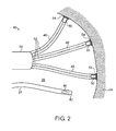
- Fig. 2 is a schematic, sectional view of a chamber of heart 26 into which catheters 24 and 40 have been inserted, in accordance with an embodiment of the present invention.
- Operational catheter 24 comprises a functional element, such as an electrode 42, at its distal tip. The electrode is brought into contact with the surface of endocardial tissue 44 and may be used to sense tissue electrical activity or to ablate tissue 44 for treatment of arrhythmias, for example.
- catheter 24 may comprise multiple electrodes or functional elements of other suitable type that is known in the art, such as an ultrasonic transducer.
- Catheter 24 also comprises a magnetic transducer 46, such as a miniature coil or a set of orthogonal coils, as described in the above-mentioned U.S. Patent 6,690,963 .
- Reference catheter 40 comprises an insertion tube 56, with multiple arms 48 extending distally from the distal end of the insertion tube. Although three arms are shown in Fig. 2 , catheter 40 may alternatively comprise a larger number of arms.
- arms 48 may be movable between a narrow, collapsed arrangement, in which the arms are disposed along the longitudinal axis of the insertion tube, and an expanded arrangement, in which the arms are spread radially apart, as shown in Fig. 2 .
- arms 48 may be retracted into the distal end of insertion tube 56, and may then be extended outward once the insertion tube is inside the target heart chamber.
- the arms may contain resilient reinforcing struts, as described in the above-mentioned U.S. Patent 7,099,712 , which cause them to spread apart so as to contact the tissue surface at locations that are spaced apart.
- each arm 48 contains a magnetic transducer 50 (which may be of a similar type to transducer 46) and an adhesive element, whose purpose is to removably attach the distal tip to the surface of endocardial tissue 44.
- the adhesive element comprises a tube 52, which extrudes a suitable biocompatible glue via the distal tip in order to create a temporary adhesive pad 54, thus attaching the distal tip to the tissue surface.
- Biocompatible glues that may be used for this purpose are described, for example, in U.S. Patent 6,428,561 , whose disclosure is incorporated by reference.
- a suitable biocompatible solvent may be extruded through the distal tips of arms 48 to dissolve the glue. This solvent may be extruded through tubes 52 or from a separate tube or reservoir (not shown).
- arms 48 may comprise other sorts of adhesive elements.
- the adhesive element may comprise a cryogenic member, which chills the distal tip sufficiently to cause the distal tip to adhere to the tissue surface by cryo-adhesion.
- a cryogenic member that may be used in a catheter, and may thus be adapted to serve as an adhesive element in catheter 40, is described, for example, in U.S. Patent Application Publication 2012/0035584 , whose disclosure is incorporated herein by reference.
- magnetic transducers 50 sense the magnetic fields produced by field generators 32 and output signals to control unit 36. These signals enable the control unit to find the coordinates of each arm 48 in the fixed frame of reference of field generators 32.
- operator 22 and/or control unit 36 may verify that the distal tips are in firm contact with the surface of tissue 44. Such contact may be verified, for example, by MRI or fluoroscopic imaging.
- a sensor (not shown) in each arm may be used to verify good contact.
- an electrode at the tip of each arm can be used to verify contact by measuring electrical impedance between the arm and the tissue, or a force sensor in each arm can sense the force exerted between the arm and the tissue.
- the adhesive elements are activated and fix the arms in place.
- the location coordinates of transducers 50 in the arms are known, relative to an external, fixed frame of reference, on the basis of sensing the magnetic fields of field generators 32.
- the adhesive elements once arms 48 have been suitably positioned in contact with the heart wall and fixed in place, operator 22 can be confident that the arms will not move during the procedure.
- the arms establish a heart frame of reference that will stably track the movement of the heart, while maintaining registration with the fixed frame of reference of the external field generators.
- control unit 36 changes the role of magnetic transducers 50 from field sensors to field generators and drives transducers 50 to generate magnetic fields.
- Magnetic transducer 46 in catheter 24 outputs signals in response to these fields, and control unit 36 processes these signals in order to find the coordinates of catheter 24 in the heart frame of reference.
- the control unit is thus able to track and display the location of catheter 24 relative to the heart itself. Because transducers 46 and 50 are in mutual proximity, it is sufficient for transducers 50 to generate relatively weak magnetic fields in order for transducer to sense the fields, and the currents needed to drive transducers 50 are thus much smaller than the driving currents of field generators 32.
- control unit 36 may drive transducer 46 to generate a magnetic field, which will be received and sensed by transducers 50.
- Control unit 36 may process these signals in an equivalent manner to that described above in order to find the position coordinates of catheter 24 in the heart frame of references.
- control unit 36 may periodically sample signals output by magnetic transducers 50 in arms 48 in response to the fields of field generators 32, in order to verify and register the locations of the arms (and of the corresponding heart frame of reference) in the fixed frame of reference of the field generators.
- field generators 32 may be used only for initial positioning, or may not be used at all.
- reference catheter 40 may be inserted into heart 26, and arms 48 may be brought into contact with and attached to tissue 44 under fluoroscopic or MRI visualization. The locations of transducers 50 in arms 48 may thus be registered with a current or pre-acquired image of the heart.
- Control unit 36 then drives transducers 50 to generate magnetic fields, as described above, and processes the signals from transducer 46 in order to find the coordinates of catheter 24 in a heart coordinate system.
- This heart coordinate system may be registered with the image (with or without use of field generators 32), or system 20 may operate without performing any sort of registration of the heart coordinate system established by arms 48.
- one or more of the magnetic transducers that are used to generate magnetic fields in the heart and thus establish the heart coordinate system may be fixed externally to the heart.
Landscapes
- Health & Medical Sciences (AREA)
- Life Sciences & Earth Sciences (AREA)
- Engineering & Computer Science (AREA)
- Animal Behavior & Ethology (AREA)
- Veterinary Medicine (AREA)
- Biomedical Technology (AREA)
- Heart & Thoracic Surgery (AREA)
- Public Health (AREA)
- General Health & Medical Sciences (AREA)
- Surgery (AREA)
- Molecular Biology (AREA)
- Medical Informatics (AREA)
- Physics & Mathematics (AREA)
- Biophysics (AREA)
- Pathology (AREA)
- Vascular Medicine (AREA)
- Hematology (AREA)
- Anesthesiology (AREA)
- Human Computer Interaction (AREA)
- Robotics (AREA)
- Nuclear Medicine, Radiotherapy & Molecular Imaging (AREA)
- Dermatology (AREA)
- Media Introduction/Drainage Providing Device (AREA)
- Surgical Instruments (AREA)
- Measurement And Recording Of Electrical Phenomena And Electrical Characteristics Of The Living Body (AREA)
- Ultra Sonic Daignosis Equipment (AREA)
- Electrotherapy Devices (AREA)
- Endoscopes (AREA)
- Magnetic Resonance Imaging Apparatus (AREA)
Abstract
Description
- The present invention relates generally to methods and devices for invasive medical treatment, and specifically to accurately sensing the location of a probe inside a body organ.
- Magnetic position sensing is now widely used in tracking the location of a catheter in the heart, both for diagnostic purposes, such as mapping cardiac electrical activity, and therapeutic, such as ablation of arrhythmogenic tissue. This type of position sensing is implemented in the CARTO® system, produced by Biosense Webster Inc. (Diamond Bar, California).
- A magnetic position sensing system of this sort is described, for example, in
U.S. Patent 6,690,963 , whose disclosure is incorporated herein by reference. The system is used for determining the location and orientation of an invasive medical instrument, such as a catheter or endoscope, relative to a reference frame. It comprises a plurality of field generators, which generate known, distinguishable fields, preferably continuous AC magnetic fields, in response to drive signals. A plurality of sensors are situated in the invasive medical instrument proximate the distal end thereof and generate sensor signals in response to the fields. A signal processor has an input for a plurality of signals corresponding to the drive signals and the sensor signals and produces three location coordinates and three orientation coordinates of a point on the invasive medical instrument. - Catheters having multiple, trackable arms are also known in the art. For example,
U.S. Patent 7,099,712 , whose disclosure is incorporated herein by reference, describes such a catheter for mapping the electrical activity in a heart. The catheter comprises a plurality of spines, each capable of obtaining electrical, mechanical and locational data. Each spine comprises at least one location sensor and at least one electrode, preferably a tip electrode and at least one ring electrode. The spines may be arranged in an expanded arrangement, wherein each spine extends radially outwardly from the catheter body, or in a collapsed arrangement, wherein each spine is disposed generally along the longitudinal axis of the catheter body. In use, at least one electrode from each spine is positioned in contact with heart tissue to map the electrical activity of the heart. The location sensors are used to determine the location of each point where the electrical activity is monitored. - Embodiments of the present invention provide apparatus and methods that enhance the accuracy of tracking the location of an invasive probe relative to the organ in which the probe is located.
- There is therefore provided, in accordance with an embodiment of the present invention, an invasive medical probe, which includes an insertion tube, having a proximal end and a distal end configured for insertion into a body of a patient. Multiple arms extend distally from the distal end of the insertion tube, each arm having a distal tip and including a magnetic transducer and an adhesive element, which is configured to removably attach the distal tip to a tissue surface within the body.
- The magnetic transducer may include one or more coils.
- In one embodiment, the adhesive element is configured to extrude a biocompatible glue via the distal tip in order to attach the distal tip to the tissue surface. In another embodiment, the adhesive element is configured to chill the distal tip so as to attach the distal tip to the tissue surface by cryo-adhesion.
- Typically, the arms are movable between a collapsed arrangement, in which the arms are disposed along a longitudinal axis of the insertion tube, and an expanded arrangement, in which the arms are spread radially apart so as to contact the tissue surface at different, respective locations.
- In a disclosed embodiment, the insertion tube is configured for insertion into a chamber of a heart of the patient, and the adhesive element of each arm is configured to removably attach the distal tip to endocardial tissue.
- There is also provided, in accordance with an embodiment of the present invention, a medical system, which includes a reference probe, including an insertion tube, having a proximal end and a distal end configured for insertion into an organ in a body of a patient, and including multiple arms extending distally from the distal end of the insertion tube. The arms have respective distal tips and include respective first magnetic transducers and adhesive elements, which are configured to removably attach the distal tips to respective locations on a tissue surface within the organ, thereby defining an organ frame of reference. An operational probe is configured for insertion into the organ in a vicinity of the reference probe and includes a second magnetic transducer and at least one functional element. A control unit is configured to drive the magnetic transducers in the arms and in the operational probe to transmit and receive magnetic fields, and is coupled to receive and process signals from the magnetic transducers in response to the magnetic fields so as to compute position coordinates of the operational probe in the organ frame of reference.
- In some embodiments, the magnetic fields transmitted by the magnetic transducers are first magnetic fields, and the signals received by the control unit in response to the first magnetic fields are first signals, wherein the system includes a plurality of field generators, which are configured to generate respective second magnetic fields from respective locations outside a body of a patient, the locations defining a fixed frame of reference, and wherein the control unit is coupled to receive and process second signals from the first magnetic transducers in response to the second magnetic fields in order to compute respective coordinates of the arms in the fixed frame of reference.
- The control unit may be coupled to register the organ frame of reference relative to the fixed frame of reference based on the respective coordinates of the distal tips. Additionally or alternatively, the control unit may be configured to drive the first magnetic transducers to transmit the first magnetic fields and is configured to receive the first signals from the second magnetic transducer in response to the first magnetic fields.
- In a disclosed embodiment, the functional element includes at least one electrode. Typically, the control unit is configured to track the position coordinates of the operational probe in the organ frame of reference, responsively to the signals, while the operational probe moves within the organ in the course of a medical procedure carried out by the operational probe.
- There is additionally provided, in accordance with an embodiment of the present invention, a method for performing a medical procedure, which includes inserting a reference probe into an organ in a body of a patient, the probe including an insertion tube and multiple arms extending distally from a distal end of the insertion tube, wherein the arms have respective distal tips and include respective first magnetic transducers. The distal tips of the arms are removably attached to respective locations on a tissue surface within the organ, thereby defining an organ frame of reference. An operational probe, including a second magnetic transducer, is inserted into the organ in a vicinity of the reference probe. The magnetic transducers in the arms and the operational probe are driven to transmit and receive magnetic fields. Signals from the magnetic transducers in response to the magnetic fields are received and processed so as to compute position coordinates of the operational probe in the organ frame of reference.
- The present invention will be more fully understood from the following detailed description of the embodiments thereof, taken together with the drawings in which:
-
-
Fig. 1 is a schematic, pictorial illustration of a system for cardiac catheterization, in accordance with an embodiment of the present invention; and -
Fig. 2 is a schematic, sectional view of a heart chamber into which catheters are inserted, in accordance with an embodiment of the present invention. - Tracking of an invasive probe, such as a catheter, relative to a body organ in which the probe is located can be difficult, especially if the organ moves as a whole within the body, or if the organ has its own internal movement. The heart, for example, has both types of movement, since in addition to beating, it has some freedom to move within the chest of a subject, while the chest as a whole moves due to respiration. On the other hand, in catheter tracking systems that are known in the art, such as the above-mentioned CARTO system, the catheter position is typically tracked in the frame of reference of field generators in fixed locations outside the body.
- Various methods have been used to compensate for heart movement in order to derive the actual position of the catheter relative to the heart. The position of the heart may be measured directly, for example by magnetic resonance imaging (MRI). Alternatively or additionally, a reference catheter may be placed and held stationary at a particular anatomical feature in the heart, such as the coronary sinus, to give a reference position reading to which the position of the moving catheter can be compared. The reference catheter, however, is prone to instability and typically indicates movement only of the heart as a whole.
- Embodiments of the present invention adopt a different approach, using a novel reference probe to establish an organ frame of reference, which is tied to the position of the heart itself and inherently compensates for heart movement. The reference probe comprises an insertion tube with multiple arms extending distally from its distal end. Each arm comprises a magnetic transducer (such as one or more miniature coils) and has an adhesive element for removably attaching the distal tip of the arm to a tissue surface within the body. The adhesive element may comprise, for example, a tube that extrudes a suitable biocompatible glue, or a cryogenic element, which chills the distal tip sufficiently to cause cryo-adhesion to the tissue surface. After the procedure, the arms are released from the tissue surface by dissolving the glue or allowing the tips of the arms to re-warm, for example.
- An operational probe, having its own magnetic transducer, is inserted into the heart in the vicinity of the reference probe, and a functional element (such as an electrode) at the distal end of the operational probe is used to perform a medical procedure, which may be diagnostic and/or therapeutic. A control unit drives the magnetic transducers in the arms and in the operational probe to transmit and receive magnetic fields, either from the arms to the operational probe or from the operational probe to the arms. The control unit receives and processes the signals that are generated by the receiving transducer or transducers in response to this magnetic field, and thus computes position coordinates of the operational probe in the organ frame of reference.
- The organ frame of reference may optionally be referred to an external, fixed frame of reference that is defined by magnetic field generators at respective locations outside the patient's body of a patient. The magnetic transducers in the arms of the reference probe sense the fields generated by these field generators, while the arms are attached to the tissue surface. The control unit receives and processes the signals generated by these magnetic transducers in response to the magnetic fields of the field generators, and thus computes the respective coordinates of the distal tips of the arms in the fixed frame of reference. In this manner, the control unit is able to register the organ frame of reference relative in the fixed frame of reference, based on the respective positions of the distal tips.
- In the embodiments that are described below, the reference probe and operational probe are described as cardiac catheters and are used in procedures that are performed in the heart. The principles of the present invention, however, are not limited to this specific context, but may rather be applied to other body organs and to probes and procedures that may be used in such organs.
-
Fig. 1 is a schematic pictorial illustration of asystem 20 for invasive treatment of aheart 26 of apatient 28, in accordance with an embodiment of the present invention. Anoperator 22, such as a cardiologist, inserts flexible probes, such ascatheters patient 28 so that the distal ends of the catheters enter a chamber of the patient's heart.Operator 22 advances the catheters so that their distal tips engage endocardial tissue at desired locations (as shown inFig. 2 ).Catheter 24 is configured as a operational catheter, with a function element, such as an electrode, for performing desired diagnostic and/or therapeutic functions inheart 26.Catheter 40 serves as a reference catheter, for use in finding the location ofcatheter 24 in the frame of reference of the heart. -
Catheters console 30. The console comprises acontrol unit 36, which sends and receives signals to and fromcatheters catheter 24 in order to ablate tissue inheart 26 and/or may receive electrical signals from the catheter in order to measure cardiac electrical activity. Alternatively or additionally,catheter 24 may be used for other diagnostic and/or therapeutic functions, as are known in the art. In addition,control unit 36 drives magnetic transducers at the distal ends ofcatheters 24 and 40 (as shown inFig. 2 ) to transmit and receive magnetic fields, and processes signals from the magnetic transducers in response to the magnetic fields so as to compute position coordinates ofcatheter 24 in a frame of reference that moves with the heart, as described below. - In the pictured embodiment,
system 20 uses magnetic position sensing to determine position coordinates ofreference catheter 40 insideheart 26 relative to a fixed frame of reference. To determine the position coordinates, adriver circuit 34 inconsole 30drives field generators 32 to generate magnetic fields within the body ofpatient 28. Typically,field generators 32 comprise coils, which are placed below the patient's torso at known positions external to the body. These coils generate magnetic fields in a predefined working volume that containsheart 26. The magnetic transducers within the end section of catheter 40 (as shown inFig. 2 ) output electrical signals in response to these magnetic fields.Control unit 36 processes these signals in order to determine position (location and/or orientation) coordinates of multiple arms extending from the distal end ofcatheter 40, as explained below.Console 30 may use the coordinates ofcatheters display 38, particularly to show the location and status ofcatheter 24. - The term "magnetic transducer," as used in the context of the present description and in the claims, refers to an element that converts electrical signals to magnetic fields and/or vice versa. In other words, when a suitable electrical driving signal is applied to a magnetic transducer, it causes the magnetic transducer to generate a magnetic field; and an appropriate magnetic field in the area of a magnetic transducer will cause the magnetic transducer to output an electrical signal. Wire coils are one example of a magnetic transducer, but other sorts of devices, such as solid-state transducers, may also be used for this purpose. Methods of magnetic position sensing and processing that may be applied by
control unit 36 in finding the coordinates ofcatheters U.S. Patent 6,690,963 and are implemented in the above-mentioned CARTO system. - Although
Fig. 1 shows a particular system configuration, other system configurations may be used in alternative embodiments of the present invention. For example, the methods described hereinbelow may be applied using position transducers of other types, such as impedance-based or ultrasonic position sensors. The term "position transducer" as used herein refers to an element that causesconsole 30 to receive signals indicative of the coordinates of the element. The position transducer may thus comprise a receiver in the catheter, which generates a position signal to the control unit based on energy received by the transducer; or it may comprise a transmitter, emitting energy that is sensed by a receiver external to the probe. Furthermore, the methods described hereinbelow may similarly be applied in diagnostic and therapeutic applications using not only catheters, but also invasive probes of other types, both in the heart and in other body organs and regions. -
Fig. 2 is a schematic, sectional view of a chamber ofheart 26 into whichcatheters Operational catheter 24 comprises a functional element, such as anelectrode 42, at its distal tip. The electrode is brought into contact with the surface ofendocardial tissue 44 and may be used to sense tissue electrical activity or to ablatetissue 44 for treatment of arrhythmias, for example. Alternatively or additionally,catheter 24 may comprise multiple electrodes or functional elements of other suitable type that is known in the art, such as an ultrasonic transducer.Catheter 24 also comprises amagnetic transducer 46, such as a miniature coil or a set of orthogonal coils, as described in the above-mentionedU.S. Patent 6,690,963 . -
Reference catheter 40 comprises aninsertion tube 56, withmultiple arms 48 extending distally from the distal end of the insertion tube. Although three arms are shown inFig. 2 ,catheter 40 may alternatively comprise a larger number of arms. For ease of insertion through the vascular system and into the heart,arms 48 may be movable between a narrow, collapsed arrangement, in which the arms are disposed along the longitudinal axis of the insertion tube, and an expanded arrangement, in which the arms are spread radially apart, as shown inFig. 2 . For example, during insertion,arms 48 may be retracted into the distal end ofinsertion tube 56, and may then be extended outward once the insertion tube is inside the target heart chamber. The arms may contain resilient reinforcing struts, as described in the above-mentionedU.S. Patent 7,099,712 , which cause them to spread apart so as to contact the tissue surface at locations that are spaced apart. - The distal tip of each
arm 48 contains a magnetic transducer 50 (which may be of a similar type to transducer 46) and an adhesive element, whose purpose is to removably attach the distal tip to the surface ofendocardial tissue 44. In the pictured example, the adhesive element comprises atube 52, which extrudes a suitable biocompatible glue via the distal tip in order to create a temporaryadhesive pad 54, thus attaching the distal tip to the tissue surface. Biocompatible glues that may be used for this purpose are described, for example, inU.S. Patent 6,428,561 , whose disclosure is incorporated by reference. Optionally, upon completion of the procedure, a suitable biocompatible solvent may be extruded through the distal tips ofarms 48 to dissolve the glue. This solvent may be extruded throughtubes 52 or from a separate tube or reservoir (not shown). - Alternatively,
arms 48 may comprise other sorts of adhesive elements. For example, the adhesive element may comprise a cryogenic member, which chills the distal tip sufficiently to cause the distal tip to adhere to the tissue surface by cryo-adhesion. A cryogenic member that may be used in a catheter, and may thus be adapted to serve as an adhesive element incatheter 40, is described, for example, inU.S. Patent Application Publication 2012/0035584 , whose disclosure is incorporated herein by reference. - After
arms 48 have been extended from insertion tube,magnetic transducers 50 sense the magnetic fields produced byfield generators 32 and output signals to controlunit 36. These signals enable the control unit to find the coordinates of eacharm 48 in the fixed frame of reference offield generators 32. Before activating the adhesive elements to fix the arms in place,operator 22 and/orcontrol unit 36 may verify that the distal tips are in firm contact with the surface oftissue 44. Such contact may be verified, for example, by MRI or fluoroscopic imaging. Alternatively or additionally, a sensor (not shown) in each arm may be used to verify good contact. For example, an electrode at the tip of each arm can be used to verify contact by measuring electrical impedance between the arm and the tissue, or a force sensor in each arm can sense the force exerted between the arm and the tissue. - Once proper contact between
arms 48 and tissues has been made and, if desired, verified, the adhesive elements are activated and fix the arms in place. The location coordinates oftransducers 50 in the arms are known, relative to an external, fixed frame of reference, on the basis of sensing the magnetic fields offield generators 32. As a result of the adhesive elements, oncearms 48 have been suitably positioned in contact with the heart wall and fixed in place,operator 22 can be confident that the arms will not move during the procedure. Thus, the arms establish a heart frame of reference that will stably track the movement of the heart, while maintaining registration with the fixed frame of reference of the external field generators. - To find the coordinates of
catheter 24 in the heart frame of reference,control unit 36 changes the role ofmagnetic transducers 50 from field sensors to field generators and drivestransducers 50 to generate magnetic fields.Magnetic transducer 46 incatheter 24 outputs signals in response to these fields, andcontrol unit 36 processes these signals in order to find the coordinates ofcatheter 24 in the heart frame of reference. The control unit is thus able to track and display the location ofcatheter 24 relative to the heart itself. Becausetransducers transducers 50 to generate relatively weak magnetic fields in order for transducer to sense the fields, and the currents needed to drivetransducers 50 are thus much smaller than the driving currents offield generators 32. - Alternatively,
control unit 36 may drivetransducer 46 to generate a magnetic field, which will be received and sensed bytransducers 50.Control unit 36 may process these signals in an equivalent manner to that described above in order to find the position coordinates ofcatheter 24 in the heart frame of references. - In either of the above configurations,
control unit 36 may periodically sample signals output bymagnetic transducers 50 inarms 48 in response to the fields offield generators 32, in order to verify and register the locations of the arms (and of the corresponding heart frame of reference) in the fixed frame of reference of the field generators. - Alternatively, in some embodiments,
field generators 32 may be used only for initial positioning, or may not be used at all. For example,reference catheter 40 may be inserted intoheart 26, andarms 48 may be brought into contact with and attached totissue 44 under fluoroscopic or MRI visualization. The locations oftransducers 50 inarms 48 may thus be registered with a current or pre-acquired image of the heart.Control unit 36 then drivestransducers 50 to generate magnetic fields, as described above, and processes the signals fromtransducer 46 in order to find the coordinates ofcatheter 24 in a heart coordinate system. This heart coordinate system may be registered with the image (with or without use of field generators 32), orsystem 20 may operate without performing any sort of registration of the heart coordinate system established byarms 48. - As another alternative (not shown in the figures) one or more of the magnetic transducers that are used to generate magnetic fields in the heart and thus establish the heart coordinate system may be fixed externally to the heart.
- Although the embodiment shown in
Fig. 2 relates to a particular type and configuration ofoperational catheter 24, the principles of the present invention may similarly be applied in tracking catheters of other types, as well as in tracking multiple operational catheters simultaneously. Furthermore, as noted earlier, these principles may similarly be applied in tracking the locations of probes in other body organs. It will thus be appreciated that the embodiments described above are cited by way of example, and that the present invention is not limited to what has been particularly shown and described hereinabove. Rather, the scope of the present invention includes both combinations and subcombinations of the various features described hereinabove, as well as variations and modifications thereof which would occur to persons skilled in the art upon reading the foregoing description and which are not disclosed in the prior art. -
- Aspect 1. A method for performing a medical procedure, comprising:
- inserting a reference probe into an organ in a body of a patient, the probe comprising an insertion tube and multiple arms extending distally from a distal end of the insertion tube, wherein the arms have respective distal tips and comprise respective first magnetic transducers;
- removably attaching the distal tips of the arms to respective locations on a tissue surface within the organ, thereby defining an organ frame of reference;
- inserting an operational probe, comprising a second magnetic transducer, into the organ in a vicinity of the reference probe;
- driving the magnetic transducers in the arms and the operational probe to transmit and receive magnetic fields; and
- receiving and processing signals from the magnetic transducers in response to the magnetic fields so as to compute position coordinates of the operational probe in the organ frame of reference.
- Aspect 2. The method according to aspect 1, wherein receiving and processing the signals comprises tracking the position coordinates of the operational probe in the organ frame of reference, responsively to the signals, while moving the operational probe within the organ in the course of the medical procedure.
- Aspect 3. The method according to aspect 1, wherein moving the operational probe comprises bringing an electrode on the operational probe into contact with multiple points on the tissue surface in the organ.
- Aspect 4. The method according to aspect 1, and comprising releasing the distal tips from the respective locations on the tissue surface upon completion of the medical procedure.
- Aspect 5. The method according to aspect 4, wherein removably attaching the distal tips comprises extruding a biocompatible glue from the distal tips, and wherein releasing the distal tips comprises extruding a biocompatible solvent to dissolve the glue.
- Aspect 6. The method according to aspect 1, wherein removably attaching the distal tips comprises chilling the distal tip so as to attach the distal tip to the tissue surface by cryo-adhesion.
- Aspect 7. The method according to aspect 1, wherein driving the magnetic transducers comprises generating first magnetic fields, and the signals received from the magnetic transducers in response to the first magnetic fields are first signals, and
wherein the method comprises generating second magnetic fields from respective locations outside a body of a patient, the locations defining a fixed frame of reference, and receiving and processing second signals from the first magnetic transducers in response to the second magnetic fields in order to compute respective coordinates of the arms in the fixed frame of reference. - Aspect 8. The method according to aspect 7, and comprising registering the organ frame of reference relative to the fixed frame of reference based on the respective coordinates of the distal tips.
- Aspect 9. The method according to aspect 1, wherein inserting the reference probe and the operational probe comprises introducing the reference probe and the operational probe into a chamber of a heart of the patient, and wherein removably attaching the distal tips comprises attaching the distal tips to endocardial tissue.
Claims (13)
- An invasive medical probe, comprising:an insertion tube, having a proximal end and a distal end configured for insertion into a body of a patient; andmultiple arms extending distally from the distal end of the insertion tube, each arm having a distal tip and comprising:a magnetic transducer; andan adhesive element, which is configured to removably attach the distal tip to a tissue surface within the body.
- The probe according to claim 1, wherein the magnetic transducer comprises one or more coils.
- The probe according to claim 1, wherein the adhesive element is configured to extrude a biocompatible glue via the distal tip in order to attach the distal tip to the tissue surface.
- The probe according to claim 1, wherein the adhesive element is configured to chill the distal tip so as to attach the distal tip to the tissue surface by cryo-adhesion.
- The probe according to claim 1, wherein the arms are movable between a collapsed arrangement, in which the arms are disposed along a longitudinal axis of the insertion tube, and an expanded arrangement, in which the arms are spread radially apart so as to contact the tissue surface at different, respective locations.
- The probe according to claim 1, wherein the insertion tube is configured for insertion into a chamber of a heart of the patient, and wherein the adhesive element of each arm is configured to removably attach the distal tip to endocardial tissue.
- A medical system, comprising:a reference probe, comprising an insertion tube, having a proximal end and a distal end configured for insertion into an organ in a body of a patient, and comprising multiple arms extending distally from the distal end of the insertion tube,wherein the arms have respective distal tips and comprise respective first magnetic transducers and adhesive elements, which are configured to removably attach the distal tips to respective locations on a tissue surface within the organ, thereby defining an organ frame of reference;an operational probe, configured for insertion into the organ in a vicinity of the reference probe and comprising a second magnetic transducer and at least one functional element; anda control unit, which is configured to drive the magnetic transducers in the arms and in the operational probe to transmit and receive magnetic fields, and which is coupled to receive and process signals from the magnetic transducers in response to the magnetic fields so as to compute position coordinates of the operational probe in the organ frame of reference.
- The system according to claim 7, wherein the magnetic fields transmitted by the magnetic transducers are first magnetic fields, and the signals received by the control unit in response to the first magnetic fields are first signals, and
wherein the system comprises a plurality of field generators, which are configured to generate respective second magnetic fields from respective locations outside a body of a patient, the locations defining a fixed frame of reference, and
wherein the control unit is coupled to receive and process second signals from the first magnetic transducers in response to the second magnetic fields in order to compute respective coordinates of the arms in the fixed frame of reference. - The system according to claim 8, wherein the control unit is coupled to register the organ frame of reference relative to the fixed frame of reference based on the respective coordinates of the distal tips.
- The system according to claim 8, wherein the control unit is configured to drive the first magnetic transducers to transmit the first magnetic fields and is configured to receive the first signals from the second magnetic transducer in response to the first magnetic fields.
- The system according to claim 7, wherein the functional element comprises at least one electrode.
- The system according to claim 7, wherein the control unit is configured to track the position coordinates of the operational probe in the organ frame of reference, responsively to the signals, while the operational probe moves within the organ in the course of a medical procedure carried out by the operational probe.
- The system according to claim 7, wherein the reference probe and operational probe are configured for insertion into a chamber of a heart of the patient, and wherein the adhesive element of each arm is configured to removably attach the distal tip to endocardial tissue.
Applications Claiming Priority (1)
| Application Number | Priority Date | Filing Date | Title |
|---|---|---|---|
| US13/687,079 US9375163B2 (en) | 2012-11-28 | 2012-11-28 | Location sensing using a local coordinate system |
Publications (2)
| Publication Number | Publication Date |
|---|---|
| EP2737869A1 true EP2737869A1 (en) | 2014-06-04 |
| EP2737869B1 EP2737869B1 (en) | 2016-03-09 |
Family
ID=49667046
Family Applications (1)
| Application Number | Title | Priority Date | Filing Date |
|---|---|---|---|
| EP13194723.6A Active EP2737869B1 (en) | 2012-11-28 | 2013-11-27 | Device for location sensing using a local coordinate system |
Country Status (7)
| Country | Link |
|---|---|
| US (1) | US9375163B2 (en) |
| EP (1) | EP2737869B1 (en) |
| JP (1) | JP6180903B2 (en) |
| CN (1) | CN103845053A (en) |
| AU (1) | AU2013260702B2 (en) |
| CA (1) | CA2834623A1 (en) |
| IL (1) | IL229441A (en) |
Cited By (2)
| Publication number | Priority date | Publication date | Assignee | Title |
|---|---|---|---|---|
| CN105534539A (en) * | 2014-10-22 | 2016-05-04 | 韦伯斯特生物官能(以色列)有限公司 | Enlargement of tracking volume by movement of imaging bed |
| EP3476290A1 (en) * | 2017-10-26 | 2019-05-01 | Biosense Webster (Israel) Ltd. | Esophageal probe with transmitting coils |
Families Citing this family (18)
| Publication number | Priority date | Publication date | Assignee | Title |
|---|---|---|---|---|
| US10143517B2 (en) * | 2014-11-03 | 2018-12-04 | LuxCath, LLC | Systems and methods for assessment of contact quality |
| US10646201B2 (en) | 2014-11-18 | 2020-05-12 | C. R. Bard, Inc. | Ultrasound imaging system having automatic image presentation |
| US10905396B2 (en) | 2014-11-18 | 2021-02-02 | C. R. Bard, Inc. | Ultrasound imaging system having automatic image presentation |
| CA2984929A1 (en) * | 2015-05-13 | 2016-11-17 | Acutus Medical, Inc. | Localization system and method useful in the acquisition and analysis of cardiac information |
| US10638954B2 (en) * | 2015-07-23 | 2020-05-05 | Biosense Webster (Israel) Ltd. | Surface registration of a CT image with a magnetic tracking system |
| US20170084036A1 (en) * | 2015-09-21 | 2017-03-23 | Siemens Aktiengesellschaft | Registration of video camera with medical imaging |
| US10244963B2 (en) | 2015-12-22 | 2019-04-02 | Biosense Webster (Israel) Ltd. | Ascertaining a position and orientation for visualizing a tool |
| US10524695B2 (en) | 2015-12-22 | 2020-01-07 | Biosense Webster (Israel) Ltd. | Registration between coordinate systems for visualizing a tool |
| US10321913B2 (en) * | 2016-08-04 | 2019-06-18 | Biosense Webster (Israel) Ltd. | Balloon positioning in a sinuplasty procedure |
| IL254009A0 (en) * | 2016-08-18 | 2017-09-28 | Nutriseal Lp | Insertion device positioning guidance system and method |
| US11007016B2 (en) | 2016-09-22 | 2021-05-18 | Walter Kusumoto | Intracardiac ultrasound catheter handheld adapter |
| WO2018057940A1 (en) * | 2016-09-22 | 2018-03-29 | Kusumoto Walter | Pericardiocentesis needle guided by cardiac electrophysiology mapping |
| US11382566B1 (en) | 2016-11-21 | 2022-07-12 | Walter Kusumoto | Lead placement assisted by electrophysiology mapping |
| CN111031958B (en) * | 2017-08-16 | 2023-09-15 | 柯惠有限合伙公司 | Synthesizing spatially aware transitions between multiple camera viewpoints during minimally invasive surgery |
| US11911144B2 (en) | 2017-08-22 | 2024-02-27 | C. R. Bard, Inc. | Ultrasound imaging system and interventional medical device for use therewith |
| EP3636171A1 (en) * | 2018-10-11 | 2020-04-15 | National University of Ireland Galway | A device for implantation in a left atrial appendage of the heart |
| US11832879B2 (en) * | 2019-03-08 | 2023-12-05 | Neuwave Medical, Inc. | Systems and methods for energy delivery |
| CN113559390B (en) * | 2020-04-09 | 2026-01-06 | 上海微创电生理医疗科技股份有限公司 | Medical interventional catheter components, medical interventional catheters and medical interventional systems |
Citations (7)
| Publication number | Priority date | Publication date | Assignee | Title |
|---|---|---|---|---|
| US6206874B1 (en) * | 1998-04-08 | 2001-03-27 | Siemens-Elema Ab | Apparatus and method for locating electrically active sites with an animal |
| US6428561B1 (en) | 1996-06-05 | 2002-08-06 | Astra Aktiebolag | Biocompatible glue |
| US6690963B2 (en) | 1995-01-24 | 2004-02-10 | Biosense, Inc. | System for determining the location and orientation of an invasive medical instrument |
| US7099712B2 (en) | 2001-12-31 | 2006-08-29 | Biosense Webster, Inc. | Catheter having multiple spines each having electrical mapping and location sensing capabilities |
| US7353067B1 (en) * | 2004-01-16 | 2008-04-01 | Pacesetter, Inc. | Implantable leads, electrode portions and methods for securing |
| EP2401980A1 (en) * | 2010-06-30 | 2012-01-04 | Biosense Webster (Israel), Ltd | Pressure sensing for a multi-arm catheter |
| US20120035584A1 (en) | 2010-08-03 | 2012-02-09 | Meditronic, Inc. | Method and Apparatus for Delivering a Lead to a Heart |
Family Cites Families (7)
| Publication number | Priority date | Publication date | Assignee | Title |
|---|---|---|---|---|
| JP3708121B2 (en) * | 1994-08-19 | 2005-10-19 | バイオセンス・インコーポレイテッド | Diagnosis and handling of medical equipment and video system |
| EP1023870B1 (en) | 1999-01-28 | 2004-09-22 | Ministero Dell' Universita' E Della Ricerca Scientifica E Tecnologica | Device for localization of endocardial electrodes |
| US20040158237A1 (en) | 2003-02-11 | 2004-08-12 | Marwan Abboud | Multi-energy ablation station |
| EP1912565B1 (en) * | 2005-08-05 | 2011-09-14 | Koninklijke Philips Electronics N.V. | Catheter navigation system |
| CN101325912B (en) * | 2005-12-15 | 2011-01-12 | 皇家飞利浦电子股份有限公司 | Systems and methods for visualizing cardiac morphology during electrophysiological mapping and therapy |
| US20100286791A1 (en) * | 2006-11-21 | 2010-11-11 | Goldsmith David S | Integrated system for the ballistic and nonballistic infixion and retrieval of implants |
| US9445859B2 (en) | 2010-01-29 | 2016-09-20 | Medtronic Cryocath Lp | Multifunctional ablation device |
-
2012
- 2012-11-28 US US13/687,079 patent/US9375163B2/en active Active
-
2013
- 2013-11-14 IL IL229441A patent/IL229441A/en active IP Right Grant
- 2013-11-21 AU AU2013260702A patent/AU2013260702B2/en not_active Ceased
- 2013-11-26 CA CA2834623A patent/CA2834623A1/en not_active Abandoned
- 2013-11-27 JP JP2013244806A patent/JP6180903B2/en active Active
- 2013-11-27 EP EP13194723.6A patent/EP2737869B1/en active Active
- 2013-11-28 CN CN201310625585.1A patent/CN103845053A/en active Pending
Patent Citations (7)
| Publication number | Priority date | Publication date | Assignee | Title |
|---|---|---|---|---|
| US6690963B2 (en) | 1995-01-24 | 2004-02-10 | Biosense, Inc. | System for determining the location and orientation of an invasive medical instrument |
| US6428561B1 (en) | 1996-06-05 | 2002-08-06 | Astra Aktiebolag | Biocompatible glue |
| US6206874B1 (en) * | 1998-04-08 | 2001-03-27 | Siemens-Elema Ab | Apparatus and method for locating electrically active sites with an animal |
| US7099712B2 (en) | 2001-12-31 | 2006-08-29 | Biosense Webster, Inc. | Catheter having multiple spines each having electrical mapping and location sensing capabilities |
| US7353067B1 (en) * | 2004-01-16 | 2008-04-01 | Pacesetter, Inc. | Implantable leads, electrode portions and methods for securing |
| EP2401980A1 (en) * | 2010-06-30 | 2012-01-04 | Biosense Webster (Israel), Ltd | Pressure sensing for a multi-arm catheter |
| US20120035584A1 (en) | 2010-08-03 | 2012-02-09 | Meditronic, Inc. | Method and Apparatus for Delivering a Lead to a Heart |
Cited By (5)
| Publication number | Priority date | Publication date | Assignee | Title |
|---|---|---|---|---|
| CN105534539A (en) * | 2014-10-22 | 2016-05-04 | 韦伯斯特生物官能(以色列)有限公司 | Enlargement of tracking volume by movement of imaging bed |
| EP3017753A1 (en) * | 2014-10-22 | 2016-05-11 | Biosense Webster (Israel) Ltd. | Enlargement of tracking volume by movement of imaging bed |
| US10674933B2 (en) | 2014-10-22 | 2020-06-09 | Biosense Webster (Israel) Ltd. | Enlargement of tracking volume by movement of imaging bed |
| EP3476290A1 (en) * | 2017-10-26 | 2019-05-01 | Biosense Webster (Israel) Ltd. | Esophageal probe with transmitting coils |
| US11000206B2 (en) | 2017-10-26 | 2021-05-11 | Biosense Webster (Israel) Ltd. | Esophageal probe with transmitting coils |
Also Published As
| Publication number | Publication date |
|---|---|
| AU2013260702A1 (en) | 2014-06-12 |
| CA2834623A1 (en) | 2014-05-28 |
| JP6180903B2 (en) | 2017-08-16 |
| US20140148688A1 (en) | 2014-05-29 |
| US9375163B2 (en) | 2016-06-28 |
| IL229441A (en) | 2017-03-30 |
| AU2013260702B2 (en) | 2017-05-11 |
| CN103845053A (en) | 2014-06-11 |
| EP2737869B1 (en) | 2016-03-09 |
| JP2014104363A (en) | 2014-06-09 |
Similar Documents
| Publication | Publication Date | Title |
|---|---|---|
| EP2737869B1 (en) | Device for location sensing using a local coordinate system | |
| AU2005234715B2 (en) | Current-based position sensing | |
| JP5031285B2 (en) | Hybrid magnetic and impedance based position detection system | |
| CN114733046B (en) | Tracking a catheter from an insertion point to a heart using impedance measurements | |
| JP6818518B2 (en) | Short symmetric contact force sensor with 4 coils | |
| JP2001500749A (en) | Medical method and apparatus using in-vivo probe | |
| JP2017086913A5 (en) | ||
| JP2010115490A (en) | Isolation of sensing circuit from pace generator | |
| EP4137051B1 (en) | Electro-anatomical mapping and annotation presented in electrophysiological procedures | |
| EP4483802A1 (en) | System for shape tracking of intrabody object subject to deformation | |
| EP3673945A1 (en) | Adjustable balloon fixation for a sheath | |
| WO2023248032A1 (en) | Applying ablation signals to both sides of tissue |
Legal Events
| Date | Code | Title | Description |
|---|---|---|---|
| PUAI | Public reference made under article 153(3) epc to a published international application that has entered the european phase |
Free format text: ORIGINAL CODE: 0009012 |
|
| 17P | Request for examination filed |
Effective date: 20131127 |
|
| AK | Designated contracting states |
Kind code of ref document: A1 Designated state(s): AL AT BE BG CH CY CZ DE DK EE ES FI FR GB GR HR HU IE IS IT LI LT LU LV MC MK MT NL NO PL PT RO RS SE SI SK SM TR |
|
| AX | Request for extension of the european patent |
Extension state: BA ME |
|
| R17P | Request for examination filed (corrected) |
Effective date: 20141204 |
|
| RBV | Designated contracting states (corrected) |
Designated state(s): AL AT BE BG CH CY CZ DE DK EE ES FI FR GB GR HR HU IE IS IT LI LT LU LV MC MK MT NL NO PL PT RO RS SE SI SK SM TR |
|
| GRAP | Despatch of communication of intention to grant a patent |
Free format text: ORIGINAL CODE: EPIDOSNIGR1 |
|
| INTG | Intention to grant announced |
Effective date: 20150603 |
|
| GRAP | Despatch of communication of intention to grant a patent |
Free format text: ORIGINAL CODE: EPIDOSNIGR1 |
|
| INTG | Intention to grant announced |
Effective date: 20151021 |
|
| GRAS | Grant fee paid |
Free format text: ORIGINAL CODE: EPIDOSNIGR3 |
|
| REG | Reference to a national code |
Ref country code: DE Ref legal event code: R079 Ref document number: 602013005346 Country of ref document: DE Free format text: PREVIOUS MAIN CLASS: A61B0019000000 Ipc: A61B0034200000 |
|
| GRAA | (expected) grant |
Free format text: ORIGINAL CODE: 0009210 |
|
| RIC1 | Information provided on ipc code assigned before grant |
Ipc: A61B 34/20 20160101AFI20160112BHEP |
|
| AK | Designated contracting states |
Kind code of ref document: B1 Designated state(s): AL AT BE BG CH CY CZ DE DK EE ES FI FR GB GR HR HU IE IS IT LI LT LU LV MC MK MT NL NO PL PT RO RS SE SI SK SM TR |
|
| REG | Reference to a national code |
Ref country code: GB Ref legal event code: FG4D |
|
| REG | Reference to a national code |
Ref country code: AT Ref legal event code: REF Ref document number: 778903 Country of ref document: AT Kind code of ref document: T Effective date: 20160315 Ref country code: CH Ref legal event code: EP |
|
| REG | Reference to a national code |
Ref country code: IE Ref legal event code: FG4D |
|
| REG | Reference to a national code |
Ref country code: DE Ref legal event code: R096 Ref document number: 602013005346 Country of ref document: DE |
|
| REG | Reference to a national code |
Ref country code: NL Ref legal event code: FP |
|
| REG | Reference to a national code |
Ref country code: LT Ref legal event code: MG4D |
|
| PG25 | Lapsed in a contracting state [announced via postgrant information from national office to epo] |
Ref country code: HR Free format text: LAPSE BECAUSE OF FAILURE TO SUBMIT A TRANSLATION OF THE DESCRIPTION OR TO PAY THE FEE WITHIN THE PRESCRIBED TIME-LIMIT Effective date: 20160309 Ref country code: ES Free format text: LAPSE BECAUSE OF FAILURE TO SUBMIT A TRANSLATION OF THE DESCRIPTION OR TO PAY THE FEE WITHIN THE PRESCRIBED TIME-LIMIT Effective date: 20160309 Ref country code: NO Free format text: LAPSE BECAUSE OF FAILURE TO SUBMIT A TRANSLATION OF THE DESCRIPTION OR TO PAY THE FEE WITHIN THE PRESCRIBED TIME-LIMIT Effective date: 20160609 Ref country code: FI Free format text: LAPSE BECAUSE OF FAILURE TO SUBMIT A TRANSLATION OF THE DESCRIPTION OR TO PAY THE FEE WITHIN THE PRESCRIBED TIME-LIMIT Effective date: 20160309 Ref country code: GR Free format text: LAPSE BECAUSE OF FAILURE TO SUBMIT A TRANSLATION OF THE DESCRIPTION OR TO PAY THE FEE WITHIN THE PRESCRIBED TIME-LIMIT Effective date: 20160610 |
|
| REG | Reference to a national code |
Ref country code: AT Ref legal event code: MK05 Ref document number: 778903 Country of ref document: AT Kind code of ref document: T Effective date: 20160309 |
|
| PG25 | Lapsed in a contracting state [announced via postgrant information from national office to epo] |
Ref country code: PL Free format text: LAPSE BECAUSE OF FAILURE TO SUBMIT A TRANSLATION OF THE DESCRIPTION OR TO PAY THE FEE WITHIN THE PRESCRIBED TIME-LIMIT Effective date: 20160309 Ref country code: SE Free format text: LAPSE BECAUSE OF FAILURE TO SUBMIT A TRANSLATION OF THE DESCRIPTION OR TO PAY THE FEE WITHIN THE PRESCRIBED TIME-LIMIT Effective date: 20160309 Ref country code: LT Free format text: LAPSE BECAUSE OF FAILURE TO SUBMIT A TRANSLATION OF THE DESCRIPTION OR TO PAY THE FEE WITHIN THE PRESCRIBED TIME-LIMIT Effective date: 20160309 Ref country code: LV Free format text: LAPSE BECAUSE OF FAILURE TO SUBMIT A TRANSLATION OF THE DESCRIPTION OR TO PAY THE FEE WITHIN THE PRESCRIBED TIME-LIMIT Effective date: 20160309 Ref country code: RS Free format text: LAPSE BECAUSE OF FAILURE TO SUBMIT A TRANSLATION OF THE DESCRIPTION OR TO PAY THE FEE WITHIN THE PRESCRIBED TIME-LIMIT Effective date: 20160309 |
|
| REG | Reference to a national code |
Ref country code: FR Ref legal event code: PLFP Year of fee payment: 4 |
|
| PG25 | Lapsed in a contracting state [announced via postgrant information from national office to epo] |
Ref country code: EE Free format text: LAPSE BECAUSE OF FAILURE TO SUBMIT A TRANSLATION OF THE DESCRIPTION OR TO PAY THE FEE WITHIN THE PRESCRIBED TIME-LIMIT Effective date: 20160309 Ref country code: IS Free format text: LAPSE BECAUSE OF FAILURE TO SUBMIT A TRANSLATION OF THE DESCRIPTION OR TO PAY THE FEE WITHIN THE PRESCRIBED TIME-LIMIT Effective date: 20160709 |
|
| PG25 | Lapsed in a contracting state [announced via postgrant information from national office to epo] |
Ref country code: PT Free format text: LAPSE BECAUSE OF FAILURE TO SUBMIT A TRANSLATION OF THE DESCRIPTION OR TO PAY THE FEE WITHIN THE PRESCRIBED TIME-LIMIT Effective date: 20160711 Ref country code: CZ Free format text: LAPSE BECAUSE OF FAILURE TO SUBMIT A TRANSLATION OF THE DESCRIPTION OR TO PAY THE FEE WITHIN THE PRESCRIBED TIME-LIMIT Effective date: 20160309 Ref country code: SK Free format text: LAPSE BECAUSE OF FAILURE TO SUBMIT A TRANSLATION OF THE DESCRIPTION OR TO PAY THE FEE WITHIN THE PRESCRIBED TIME-LIMIT Effective date: 20160309 Ref country code: AT Free format text: LAPSE BECAUSE OF FAILURE TO SUBMIT A TRANSLATION OF THE DESCRIPTION OR TO PAY THE FEE WITHIN THE PRESCRIBED TIME-LIMIT Effective date: 20160309 Ref country code: RO Free format text: LAPSE BECAUSE OF FAILURE TO SUBMIT A TRANSLATION OF THE DESCRIPTION OR TO PAY THE FEE WITHIN THE PRESCRIBED TIME-LIMIT Effective date: 20160309 Ref country code: SM Free format text: LAPSE BECAUSE OF FAILURE TO SUBMIT A TRANSLATION OF THE DESCRIPTION OR TO PAY THE FEE WITHIN THE PRESCRIBED TIME-LIMIT Effective date: 20160309 |
|
| REG | Reference to a national code |
Ref country code: DE Ref legal event code: R097 Ref document number: 602013005346 Country of ref document: DE |
|
| PLBE | No opposition filed within time limit |
Free format text: ORIGINAL CODE: 0009261 |
|
| STAA | Information on the status of an ep patent application or granted ep patent |
Free format text: STATUS: NO OPPOSITION FILED WITHIN TIME LIMIT |
|
| PG25 | Lapsed in a contracting state [announced via postgrant information from national office to epo] |
Ref country code: DK Free format text: LAPSE BECAUSE OF FAILURE TO SUBMIT A TRANSLATION OF THE DESCRIPTION OR TO PAY THE FEE WITHIN THE PRESCRIBED TIME-LIMIT Effective date: 20160309 |
|
| 26N | No opposition filed |
Effective date: 20161212 |
|
| PG25 | Lapsed in a contracting state [announced via postgrant information from national office to epo] |
Ref country code: BG Free format text: LAPSE BECAUSE OF FAILURE TO SUBMIT A TRANSLATION OF THE DESCRIPTION OR TO PAY THE FEE WITHIN THE PRESCRIBED TIME-LIMIT Effective date: 20160609 |
|
| PG25 | Lapsed in a contracting state [announced via postgrant information from national office to epo] |
Ref country code: SI Free format text: LAPSE BECAUSE OF FAILURE TO SUBMIT A TRANSLATION OF THE DESCRIPTION OR TO PAY THE FEE WITHIN THE PRESCRIBED TIME-LIMIT Effective date: 20160309 |
|
| REG | Reference to a national code |
Ref country code: CH Ref legal event code: PL |
|
| PG25 | Lapsed in a contracting state [announced via postgrant information from national office to epo] |
Ref country code: LI Free format text: LAPSE BECAUSE OF NON-PAYMENT OF DUE FEES Effective date: 20161130 Ref country code: CH Free format text: LAPSE BECAUSE OF NON-PAYMENT OF DUE FEES Effective date: 20161130 |
|
| REG | Reference to a national code |
Ref country code: IE Ref legal event code: MM4A |
|
| PG25 | Lapsed in a contracting state [announced via postgrant information from national office to epo] |
Ref country code: LU Free format text: LAPSE BECAUSE OF NON-PAYMENT OF DUE FEES Effective date: 20161130 |
|
| REG | Reference to a national code |
Ref country code: FR Ref legal event code: PLFP Year of fee payment: 5 |
|
| PG25 | Lapsed in a contracting state [announced via postgrant information from national office to epo] |
Ref country code: IE Free format text: LAPSE BECAUSE OF NON-PAYMENT OF DUE FEES Effective date: 20161127 |
|
| PG25 | Lapsed in a contracting state [announced via postgrant information from national office to epo] |
Ref country code: CY Free format text: LAPSE BECAUSE OF FAILURE TO SUBMIT A TRANSLATION OF THE DESCRIPTION OR TO PAY THE FEE WITHIN THE PRESCRIBED TIME-LIMIT Effective date: 20160309 Ref country code: HU Free format text: LAPSE BECAUSE OF FAILURE TO SUBMIT A TRANSLATION OF THE DESCRIPTION OR TO PAY THE FEE WITHIN THE PRESCRIBED TIME-LIMIT; INVALID AB INITIO Effective date: 20131127 |
|
| PG25 | Lapsed in a contracting state [announced via postgrant information from national office to epo] |
Ref country code: MC Free format text: LAPSE BECAUSE OF FAILURE TO SUBMIT A TRANSLATION OF THE DESCRIPTION OR TO PAY THE FEE WITHIN THE PRESCRIBED TIME-LIMIT Effective date: 20160309 Ref country code: MK Free format text: LAPSE BECAUSE OF FAILURE TO SUBMIT A TRANSLATION OF THE DESCRIPTION OR TO PAY THE FEE WITHIN THE PRESCRIBED TIME-LIMIT Effective date: 20160309 |
|
| PG25 | Lapsed in a contracting state [announced via postgrant information from national office to epo] |
Ref country code: MT Free format text: LAPSE BECAUSE OF NON-PAYMENT OF DUE FEES Effective date: 20161127 |
|
| REG | Reference to a national code |
Ref country code: FR Ref legal event code: PLFP Year of fee payment: 6 |
|
| PG25 | Lapsed in a contracting state [announced via postgrant information from national office to epo] |
Ref country code: AL Free format text: LAPSE BECAUSE OF FAILURE TO SUBMIT A TRANSLATION OF THE DESCRIPTION OR TO PAY THE FEE WITHIN THE PRESCRIBED TIME-LIMIT Effective date: 20160309 Ref country code: TR Free format text: LAPSE BECAUSE OF FAILURE TO SUBMIT A TRANSLATION OF THE DESCRIPTION OR TO PAY THE FEE WITHIN THE PRESCRIBED TIME-LIMIT Effective date: 20160309 |
|
| PGFP | Annual fee paid to national office [announced via postgrant information from national office to epo] |
Ref country code: BE Payment date: 20191017 Year of fee payment: 7 |
|
| REG | Reference to a national code |
Ref country code: BE Ref legal event code: MM Effective date: 20201130 |
|
| PG25 | Lapsed in a contracting state [announced via postgrant information from national office to epo] |
Ref country code: BE Free format text: LAPSE BECAUSE OF NON-PAYMENT OF DUE FEES Effective date: 20201130 |
|
| PGFP | Annual fee paid to national office [announced via postgrant information from national office to epo] |
Ref country code: NL Payment date: 20221019 Year of fee payment: 10 |
|
| REG | Reference to a national code |
Ref country code: NL Ref legal event code: MM Effective date: 20231201 |
|
| PG25 | Lapsed in a contracting state [announced via postgrant information from national office to epo] |
Ref country code: NL Free format text: LAPSE BECAUSE OF NON-PAYMENT OF DUE FEES Effective date: 20231201 |
|
| PG25 | Lapsed in a contracting state [announced via postgrant information from national office to epo] |
Ref country code: NL Free format text: LAPSE BECAUSE OF NON-PAYMENT OF DUE FEES Effective date: 20231201 |
|
| PGFP | Annual fee paid to national office [announced via postgrant information from national office to epo] |
Ref country code: FR Payment date: 20250930 Year of fee payment: 13 |
|
| PGFP | Annual fee paid to national office [announced via postgrant information from national office to epo] |
Ref country code: DE Payment date: 20250930 Year of fee payment: 13 |
|
| PGFP | Annual fee paid to national office [announced via postgrant information from national office to epo] |
Ref country code: GB Payment date: 20251001 Year of fee payment: 13 |
|
| PGFP | Annual fee paid to national office [announced via postgrant information from national office to epo] |
Ref country code: IT Payment date: 20251022 Year of fee payment: 13 |