EP2737795A1 - Aircraft bird strike prevention - Google Patents
Aircraft bird strike prevention Download PDFInfo
- Publication number
- EP2737795A1 EP2737795A1 EP13194092.6A EP13194092A EP2737795A1 EP 2737795 A1 EP2737795 A1 EP 2737795A1 EP 13194092 A EP13194092 A EP 13194092A EP 2737795 A1 EP2737795 A1 EP 2737795A1
- Authority
- EP
- European Patent Office
- Prior art keywords
- aircraft
- repellant
- runway
- bird
- airspace
- Prior art date
- Legal status (The legal status is an assumption and is not a legal conclusion. Google has not performed a legal analysis and makes no representation as to the accuracy of the status listed.)
- Granted
Links
- 230000002265 prevention Effects 0.000 title 1
- 230000002085 persistent effect Effects 0.000 claims abstract description 22
- 238000007599 discharging Methods 0.000 claims abstract description 21
- 239000002245 particle Substances 0.000 claims description 13
- 238000000034 method Methods 0.000 claims description 11
- 230000008016 vaporization Effects 0.000 claims description 10
- 239000007788 liquid Substances 0.000 claims description 6
- 238000013459 approach Methods 0.000 description 8
- 230000002940 repellent Effects 0.000 description 8
- 239000005871 repellent Substances 0.000 description 8
- VAMXMNNIEUEQDV-UHFFFAOYSA-N methyl anthranilate Chemical compound COC(=O)C1=CC=CC=C1N VAMXMNNIEUEQDV-UHFFFAOYSA-N 0.000 description 4
- 229940102398 methyl anthranilate Drugs 0.000 description 2
- 230000000712 assembly Effects 0.000 description 1
- 238000000429 assembly Methods 0.000 description 1
- 238000013480 data collection Methods 0.000 description 1
- 230000010006 flight Effects 0.000 description 1
- 230000008014 freezing Effects 0.000 description 1
- 238000007710 freezing Methods 0.000 description 1
- 230000005484 gravity Effects 0.000 description 1
- 238000010438 heat treatment Methods 0.000 description 1
- 238000009434 installation Methods 0.000 description 1
- 238000001556 precipitation Methods 0.000 description 1
- 238000005086 pumping Methods 0.000 description 1
- 230000001846 repelling effect Effects 0.000 description 1
- 230000000007 visual effect Effects 0.000 description 1
Images
Classifications
-
- B—PERFORMING OPERATIONS; TRANSPORTING
- B64—AIRCRAFT; AVIATION; COSMONAUTICS
- B64D—EQUIPMENT FOR FITTING IN OR TO AIRCRAFT; FLIGHT SUITS; PARACHUTES; ARRANGEMENT OR MOUNTING OF POWER PLANTS OR PROPULSION TRANSMISSIONS IN AIRCRAFT
- B64D1/00—Dropping, ejecting, releasing or receiving articles, liquids, or the like, in flight
- B64D1/16—Dropping or releasing powdered, liquid, or gaseous matter, e.g. for fire-fighting
- B64D1/18—Dropping or releasing powdered, liquid, or gaseous matter, e.g. for fire-fighting by spraying, e.g. insecticides
-
- B—PERFORMING OPERATIONS; TRANSPORTING
- B64—AIRCRAFT; AVIATION; COSMONAUTICS
- B64D—EQUIPMENT FOR FITTING IN OR TO AIRCRAFT; FLIGHT SUITS; PARACHUTES; ARRANGEMENT OR MOUNTING OF POWER PLANTS OR PROPULSION TRANSMISSIONS IN AIRCRAFT
- B64D45/00—Aircraft indicators or protectors not otherwise provided for
-
- A—HUMAN NECESSITIES
- A01—AGRICULTURE; FORESTRY; ANIMAL HUSBANDRY; HUNTING; TRAPPING; FISHING
- A01M—CATCHING, TRAPPING OR SCARING OF ANIMALS; APPARATUS FOR THE DESTRUCTION OF NOXIOUS ANIMALS OR NOXIOUS PLANTS
- A01M29/00—Scaring or repelling devices, e.g. bird-scaring apparatus
- A01M29/12—Scaring or repelling devices, e.g. bird-scaring apparatus using odoriferous substances, e.g. aromas, pheromones or chemical agents
-
- B—PERFORMING OPERATIONS; TRANSPORTING
- B64—AIRCRAFT; AVIATION; COSMONAUTICS
- B64D—EQUIPMENT FOR FITTING IN OR TO AIRCRAFT; FLIGHT SUITS; PARACHUTES; ARRANGEMENT OR MOUNTING OF POWER PLANTS OR PROPULSION TRANSMISSIONS IN AIRCRAFT
- B64D1/00—Dropping, ejecting, releasing or receiving articles, liquids, or the like, in flight
- B64D1/16—Dropping or releasing powdered, liquid, or gaseous matter, e.g. for fire-fighting
-
- B—PERFORMING OPERATIONS; TRANSPORTING
- B64—AIRCRAFT; AVIATION; COSMONAUTICS
- B64D—EQUIPMENT FOR FITTING IN OR TO AIRCRAFT; FLIGHT SUITS; PARACHUTES; ARRANGEMENT OR MOUNTING OF POWER PLANTS OR PROPULSION TRANSMISSIONS IN AIRCRAFT
- B64D45/00—Aircraft indicators or protectors not otherwise provided for
- B64D2045/0095—Devices specially adapted to avoid bird strike
Definitions
- Bird strikes can cause damage to commercial aircraft.
- the resulting aircraft damage is costly to repair.
- aircraft downtime during repair is costly as it results in lost revenues for aircraft operators. So, it is desirable to minimize bird strikes.
- an aircraft comprises an aircraft body, and apparatus, carried by the body, for discharging a persistent vapor of bird repellant into an elevated airspace.
- a method comprises discharging a persistent vapor of bird repellant from a flying aircraft into an elevated airspace to prevent birds from striking other aircraft in the elevated airspace.
- an apparatus configured to be carried upon an aircraft.
- the apparatus comprises a tank, a vaporizing nozzle, and control for causing bird repellant to be discharged from the tank via the nozzle.
- the control is configured to cause the bird repellant to be discharged into a selected elevated airspace above an airport runway.
- an aircraft comprising: an aircraft body; and apparatus, carried by the body, for discharging a persistent vapor of bird repellant into an elevated airspace.
- the apparatus includes a liquid bird repellant tank and a vaporizing nozzle.
- the vaporizing nozzle is configured to deliver a persistent vapor of bird repellant having a particle size of 30 microns or less.
- the tank is filled with a liquid bird repellant including methyl anthranilate.
- the apparatus further includes a removable base panel, the tank mounted upon said base.
- the body includes empennage; and wherein said apparatus is mounted within said empennage.
- the apparatus further includes a control for causing the nozzle to discharge bird repellant into a selected elevated airspace adjacent a runway.
- the control includes a pump, a weight-off-wheels sensor, and a controller, responsive to the sensor, for controlling operation of the pump.
- the control includes a pump and a digital processor programmed to control operation of the pump according to live aircraft data.
- the control is configured to discharge the bird repellant into an elevated airspace from the runway to an elevation of about 3000 feet above the runway.
- a method comprising discharging a persistent vapor of bird repellant from a flying aircraft into an elevated airspace to prevent birds from striking other aircraft in the elevated airspace.
- the vapor of bird repellant is discharged into a flight path to a runway at an airport.
- the bird repellant is discharged from the runway to an elevation of substantially 3000 feet above the runway.
- the repellant is carried and discharged by a first aircraft to protect other aircraft flying into and departing an airport.
- the repellant is discharged by an unmanned aircraft.
- the repellant is discharged by a commercial aircraft.
- an apparatus configured to be carried upon an aircraft, said apparatus comprising a tank, a vaporizing nozzle, and control for causing bird repellant to be discharged from the tank via the nozzle; the control configured to cause the bird repellant to be discharged into a selected elevated airspace above an airport runway.
- control includes a weight-on-wheels sensor.
- control includes a digital processor for receiving live aircraft data to perform at least one of modifying discharge rates, altering altitude of discharge, and abort a planned discharge.
- control is also configured to vary particle size of the discharged bird repellant.
- methyl anthranilate or another bird repellant may be used to protect flying aircraft from flying bird strikes within the runway flight path corridor.
- MA methyl anthranilate
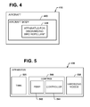
- FIG. 4 illustrates an aircraft 410 for discharging bird repellent into a runway flight path corridor.
- the aircraft 410 may be manned (for example, a general aviation aircraft, a helicopter, or a commercial passenger or freight aircraft) or unmanned (for example, a remotely piloted vehicle, or "RPV” or an unmanned autonomous vehicle or "UAV").
- the aircraft 410 includes a body 420 and an apparatus 430, carried by the body 420, for discharging a persistent vapor of bird repellant into a runway flight path corridor.
- major components of the body 420 may include a fuselage, wing assemblies and empennage.
- the apparatus 430 may be carried by any of these major components.
- the apparatus 430 may be stored, for example, in a payload bay.
- the aircraft 410 discharging the bird repellant does not protect itself against bird strikes in the runway flight path corridor. Rather, it discharges the bird repellant into the runway flight path corridor so subsequent aircraft entering the runway flight path corridor are protected. Moreover, the aircraft 410 does not necessarily discharge the bird repellant directly into the runway flight path corridor.
- the aircraft 410 may discharge the bird repellant into a selected elevated airspace such that the bird repellant enters into the runway flight path corridor. For instance, the bird repellant may be discharged upwind of the runway flight path corridor and blown from the selected elevated airspace into the runway flight path corridor.
- the aircraft 410 discharging bird repellant into the selected airspace may be flown along the approach flight path(s) to an airport, and along the departure flight path(s) from an airport, either within these paths, or upwind of these flight paths, most desirably during daylight hours and during the months of the year when bird strikes are most common.
- the apparatus 430 may be configured to be easily installed onto and removable from an aircraft 410.
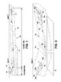
- Figure 1 provides a diagrammatic view of an airport with a runway 10 to which a commercial aircraft 12 approaches along a landing corridor 14, and from which aircraft 16 departs along a take off corridor 18.
- the corridors 14 and 18 have a thickness in the vertical direction of but a few hundred feet, and extend laterally of the alignment of the runway 10 by a mile or less within the relevant altitude and distance from the runway 10. That is, as discussed above, the majority of bird strikes occur at elevations of 3000 feet or less. So, it is in the elevations from 3000 ft. above runway 10, down to the runway 10, and within the flight path corridors 14, 18 that birds are to be repelled in order to prevent flying bird strikes by aircraft.
- Figure 1 well illustrates the airspace (generally indicated with numeral 20, and including landing corridor 14 and take off corridor 18) from which it is desired to repel flying birds in order to make this airspace safer for the transit of aircraft using these flight paths to and from the runway 10.
- Figure 2 depicts a portion of the airspace 20 at an enlarged size so that it is seen that a commercial aircraft 22 flies along paths as are generally indicated by the arrows 24, 26, and 28.
- Arrow 24 depicts the aircraft 22 flying relative to (possibly within) the approach or landing corridor 14. That is, it is to be noted that the aircraft 22 may actually fly within the corridor 14, or may fly upwind of but generally parallel to and at elevations corresponding generally with the corridor 14, depending on wind conditions at a particular time.
- the length of the runway 10 has been foreshortened in both of Figures 1 and 2 .
- Arrow 26 depicts the aircraft 22 transitioning along the length of the runway 10 (generally parallel to but not necessarily over runway 10) from landing corridor 14 to take off corridor 18.
- Arrow 28 similarly depicts aircraft 22 flying relative to (possibly within) the take off corridor 18.
- the aircraft 22 discharges, from an apparatus generally indicated with dashed line box 30 on Figure 2 , a persistent bird repellant into a selected one or both of the landing corridor 14 and take off corridor 18.
- FIG. 2 an apparatus 30 for discharging a persistent vapor bird repellant is depicted by a dashed-line box.
- Figure 2 shows the apparatus 30 aboard the empennage 22d of the aircraft 22.
- the apparatus 30 may be located in an auxiliary power unit (APU) bay in the empennage 22d.
- APU auxiliary power unit
- the location of the apparatus 30 is not limited to the empennage 22d.
- the apparatus 30 may be located in or near a fuselage 22a, landing gear bay 22b, or in a wing-to-body fairing 22c of the aircraft 22.
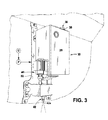
- Figure 3 illustrates one embodiment of an apparatus 30 for discharging a persistent vapor bird repellant from aircraft 22 and into the airspace 20.
- the apparatus 30 may include a base or panel 32, which is adapted for quick installation into and removal from the aircraft 22. That is, the apparatus 30 when carried aboard a general aviation aircraft, aboard a helicopter, or even aboard a commercial passenger or freight aircraft, may be installed within the aircraft during the months of the year when bird strikes are most common, and is preferably removed for the remainder of the year.
- the apparatus 30 may receive power for its operation (electrical power, for example - indicated with the character "P" on Figure 3 ) as well as control signals ("on" and "off” signals, for example - indicated on Figure 3 with the character "C”) from the aircraft 22 upon which it is carried.
- a tank 34 having an inlet 36 for receiving MA or another liquid bird repellant.
- the inlet 36 is closed by a cap 38.
- a pump 40 also mounted to the panel 32 receives bird repellant from tank 34 and during operation of the pump 40 delivers the liquid bird repellant pressurized to an atomizing or vaporizing nozzle 42.
- the nozzle 42 preferably extends at least slightly outwardly of the aircraft carrying the apparatus 30 and into the surrounding air stream so, during flight, it can discharge atomized bird repellant in the form of a persistent vapor.
- the nozzle 42 may extend through a hole in an APU access door.
- This vapor of atomized persistent bird repellant is delivered through an orifice (generally indicated at 42a) in the nozzle 42.
- Particle size of the vapor may be set according to the size of the orifice 42a Particle size of the vapor may be about 30 microns or less.
- the atomized vapor of bird repellent has a vapor particle size of from about 5 microns to about 25 microns.
- Such a small particle size provides a vapor that is essentially "dry” and leaves no wet residue, and which is very persistent within the runway flight path corridor. That is, this small particle size allows the persistent vapor of bird repellent to remain suspended in the runway flight path corridor, so that the bird repellent does not sink to the ground. Accordingly, as the persistent vapor of bird repellent disperses into the runway flight path corridor, flying birds are repelled from the runway flight path corridor, and subsequent aircraft can more safely transit this airspace to and from the airport and runway 10.
- the base panel 32 may include a heating element with temperature sensing to maintain the repellent in a liquid state for dispersal into the selected elevated airspace on approach for landing. Even during summer, the APU bay for example would be cold at altitude as the APU is not generally used in flight. Repellent carried in flight but reserved for dispersal on landing would be heated in order to prevent freezing.
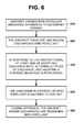
- the apparatus 430 includes a tank 520, vaporizing nozzle 530, and control 540 for causing bird repellant to be discharged from the tank 520 via the nozzle 530.
- the nozzle 530 delivers particles of fixed size (for instance, by using a fixed orifice size). In other embodiments, the particle size may be varied.
- a single nozzle 530 having a variable orifice may be used.
- the apparatus 430 includes at least one additional nozzle (not shown), where the different nozzles have different orifice sizes. The nozzle discharging a desired particle size is selected.
- the control 540 may include a pump 542, which receives electrical power from the aircraft 410 and pumps repellant from the tank 520 to the nozzle 530.
- Other embodiments may eliminate the pump and use other means to discharge the bird repellant (e.g., an airflow assisted gravity feed system).
- the control 540 may further include a controller 544 for controlling the pump 542.
- the controller 544 may be analog or digital. Although located onboard the aircraft 410, the controller 544 is preferably not integrated electronically with other onboard systems (to avoid full failure could affect the other onboard systems).
- the controller 544 may include a simple on-off switch operated manually by the crew of the aircraft or automatically by aircraft avionics.
- the control 540 may include a "weight-on-wheels" sensor, such that the repellant is not discharged while the aircraft is on the ground with weight on its landing gear. Once the sensor senses that the aircraft is off the ground, the controller 544 causes the pump 542 to start pumping bird repellant to the vaporizing nozzle 530.
- the controller 544 may include a digital processor that is programmed to control the operation of the pump 542.
- the digital processor may be programmed to control the pump 542 to discharge the bird repellant at a rate that follows a predetermined profile or a profile determined by real time data collection.
- the digital processor may also be programmed to make a "go" or “no go” decision to discharge based on a state table in response to real time data collected by onboard sensing systems and advanced radar systems, and also in response to inputs from pilots, air traffic control, and ground service spotters (e.g., spotters with visual "eyes on birds" reports).
- the controller 544 may also control the size of the particle discharged through the nozzle.
- the controller 544 may control orifice size of a nozzle having a variable orifice.
- the controller 544 may select a nozzle among a plurality of nozzles having different orifice sizes.
- the digital processor may be programmed to communicate with multiple on board sensing and information systems allowing the apparatus 430 to combine information regarding weather conditions (e.g., high winds, heavy precipitation, temperature) and more detailed information such as bird sighting and bird strike reports, advanced onboard radar systems reports, general air traffic congestion, pilot inputs, etc.
- the digital processor may use this information to modify dispersal rates, alter altitude of dispersal, or abort a planned dispersal.
- FIG. 6 illustrates a method of using the apparatus with digital controller to discharge bird repellant into a selected elevated airspace.
- an aircraft carries the apparatus to an airport runway.
- the aircraft takes off, and begins discharging the bird repellant under control of the digital controller.
- the digital controller performs at least one of modifying discharge rate, altering altitude of discharge, and aborting a planned discharge.
- the digital controller either stops the discharge or allows the tank to run out of bird repellant.
- the digital controller leaves an amount of bird repellant in the tank for use during approach and landing.
- the digital controller causes the bird repellant to be discharged into the elevated airspace.
- the bird repellant clears the runway flight path corridor of birds. As a result, subsequent aircraft entering the runway flight path corridor are protected against bird strike.
- An apparatus herein may be refilled with bird repellant and used during each flight. However, use of an apparatus herein is not so limited. An apparatus herein may be used only when needed. For example, bird repellant is discharged according to a schedule of every tenth departure, when only a few birds are known to be in the area. Later, bird repellent is discharged on every other departure, but only for afternoon flights.
- An apparatus herein is not limited to discharging bird repellant into the selected elevated airspace. For instance, if birds are sighted on the ground, an apparatus herein may discharge bird repellant on taxi. A wetter vapor that sinks to the ground may be desired for such discharge. In the case of a single nozzle having a variable orifice, orifice size may be increased to obtain a wetter vapor. In the case of multiple nozzles with different orifice sizes, the nozzle with a suitable orifice may be selected to obtain a wetter vapor.
- An apparatus herein is not limited to commercial airports. An apparatus herein may be used, for example, in regional airports and military bases.
Landscapes
- Life Sciences & Earth Sciences (AREA)
- Engineering & Computer Science (AREA)
- Aviation & Aerospace Engineering (AREA)
- Pest Control & Pesticides (AREA)
- Birds (AREA)
- Toxicology (AREA)
- General Health & Medical Sciences (AREA)
- Insects & Arthropods (AREA)
- Health & Medical Sciences (AREA)
- Wood Science & Technology (AREA)
- Zoology (AREA)
- Environmental Sciences (AREA)
- Traffic Control Systems (AREA)
- Catching Or Destruction (AREA)
Abstract
Description
- Bird strikes can cause damage to commercial aircraft. The resulting aircraft damage is costly to repair. Also, aircraft downtime during repair is costly as it results in lost revenues for aircraft operators. So, it is desirable to minimize bird strikes.
- Some have suggested putting lights (flashing lights, for example) and/or noise makers on the aircraft themselves. Such expedients have proven ineffective.
- Accordingly, a more effective way of keeping flying birds out of the flight path of aircraft at airports is needed.
- According to an embodiment herein, an aircraft comprises an aircraft body, and apparatus, carried by the body, for discharging a persistent vapor of bird repellant into an elevated airspace.
- According to another embodiment herein, a method comprises discharging a persistent vapor of bird repellant from a flying aircraft into an elevated airspace to prevent birds from striking other aircraft in the elevated airspace.
- According to another embodiment herein, an apparatus is configured to be carried upon an aircraft. The apparatus comprises a tank, a vaporizing nozzle, and control for causing bird repellant to be discharged from the tank via the nozzle. The control is configured to cause the bird repellant to be discharged into a selected elevated airspace above an airport runway.
- According to an aspect of the present disclosure there is provided an aircraft comprising: an aircraft body; and apparatus, carried by the body, for discharging a persistent vapor of bird repellant into an elevated airspace.
- Advantageously the apparatus includes a liquid bird repellant tank and a vaporizing nozzle. Preferably the vaporizing nozzle is configured to deliver a persistent vapor of bird repellant having a particle size of 30 microns or less. Preferably the tank is filled with a liquid bird repellant including methyl anthranilate. Preferably the apparatus further includes a removable base panel, the tank mounted upon said base. Preferably the body includes empennage; and wherein said apparatus is mounted within said empennage. Preferably the apparatus further includes a control for causing the nozzle to discharge bird repellant into a selected elevated airspace adjacent a runway. Preferably the control includes a pump, a weight-off-wheels sensor, and a controller, responsive to the sensor, for controlling operation of the pump. Preferably the control includes a pump and a digital processor programmed to control operation of the pump according to live aircraft data. Preferably the control is configured to discharge the bird repellant into an elevated airspace from the runway to an elevation of about 3000 feet above the runway.
- According to a further aspect of the present disclosure there is provided a method comprising discharging a persistent vapor of bird repellant from a flying aircraft into an elevated airspace to prevent birds from striking other aircraft in the elevated airspace.
- Advantageously the vapor of bird repellant is discharged into a flight path to a runway at an airport. Preferably the bird repellant is discharged from the runway to an elevation of substantially 3000 feet above the runway.
- Advantageously the repellant is carried and discharged by a first aircraft to protect other aircraft flying into and departing an airport. Preferably the repellant is discharged by an unmanned aircraft. Preferably the repellant is discharged by a commercial aircraft.
- According to a yet further aspect of the present disclosure there is provided an apparatus configured to be carried upon an aircraft, said apparatus comprising a tank, a vaporizing nozzle, and control for causing bird repellant to be discharged from the tank via the nozzle; the control configured to cause the bird repellant to be discharged into a selected elevated airspace above an airport runway.
- Advantageously the control includes a weight-on-wheels sensor.
- Advantageously the control includes a digital processor for receiving live aircraft data to perform at least one of modifying discharge rates, altering altitude of discharge, and abort a planned discharge.
- Advantageously the control is also configured to vary particle size of the discharged bird repellant.
- These features and functions may be achieved independently in various embodiments or may be combined in other embodiments. Further details of the embodiments can be seen with reference to the following description and drawings.
-
-
Figure 1 provides a diagrammatic representation of an airport with a runway, and of a landing approach flight path and a take off departure flight path to and from the runway, respectively. -
Figure 2 is an enlarged fragmentary view of a portion ofFigure 1 , illustrating a method of protecting the airspace of the landing and take off flight paths by repelling birds from this airspace. -
Figure 3 provides a perspective view of an apparatus carried upon an aircraft for discharging into the airspace identified inFigures 1 and 2 a persistent vapor of a bird repellant which will repel flying birds. -
Figure 4 is an illustration of an aircraft including apparatus for discharging a persistent vapor of a bird repellant into a selected airspace. -
Figure 5 is an illustration of an example of an apparatus for discharging a persistent vapor of a bird repellant into an elevated airspace. -
Figure 6 is an illustration of a method of discharging a persistent vapor of a bird repellant into an elevated airspace. - Recent bird strike studies have shown that over 90% of bird strikes occur at altitudes of less than 3000 feet, and within 9 miles of an airport runway for aircraft approaching landing, or within 2.5 miles of the airport runway following takeoff for an aircraft departing an airport. By far, the majority of bird strikes occur during approach to a landing, almost always during daylight hours, and during the summer and fall months (i.e., July through October). Both for aircraft approaching landing, and for those departing an airport, the elevated airspace (or flight path) to be occupied by the aircraft and to be kept free of flying birds is generally aligned with an airport runway, and extends to an elevation of about 3000 feet (sloping downwardly toward landing and sloping more steeply upwardly following takeoff), and extends generally less than a mile laterally of the runway alignment. This relatively thin flight path corridor at an airport runway (hereinafter the "runway flight path corridor") is the airspace from which birds should be excluded if bird strikes are to be reduced or eliminated.
- In view of the above, methyl anthranilate ("MA") or another bird repellant may be used to protect flying aircraft from flying bird strikes within the runway flight path corridor. By discharging MA or another bird repellant into the runway flight path corridor in a vapor form that does not sink and remains persistently in the air, birds will be repelled and bird strikes against aircraft approaching and departing a runway will be significantly reduced or eliminated.
- Reference is made to
Figure 4 , which illustrates anaircraft 410 for discharging bird repellent into a runway flight path corridor. Theaircraft 410 may be manned (for example, a general aviation aircraft, a helicopter, or a commercial passenger or freight aircraft) or unmanned (for example, a remotely piloted vehicle, or "RPV" or an unmanned autonomous vehicle or "UAV"). Theaircraft 410 includes abody 420 and anapparatus 430, carried by thebody 420, for discharging a persistent vapor of bird repellant into a runway flight path corridor. For a commercial aircraft, major components of thebody 420 may include a fuselage, wing assemblies and empennage. Theapparatus 430 may be carried by any of these major components. For an unmanned aircraft, theapparatus 430 may be stored, for example, in a payload bay. - The
aircraft 410 discharging the bird repellant does not protect itself against bird strikes in the runway flight path corridor. Rather, it discharges the bird repellant into the runway flight path corridor so subsequent aircraft entering the runway flight path corridor are protected. Moreover, theaircraft 410 does not necessarily discharge the bird repellant directly into the runway flight path corridor. Theaircraft 410 may discharge the bird repellant into a selected elevated airspace such that the bird repellant enters into the runway flight path corridor. For instance, the bird repellant may be discharged upwind of the runway flight path corridor and blown from the selected elevated airspace into the runway flight path corridor. - The
aircraft 410 discharging bird repellant into the selected airspace may be flown along the approach flight path(s) to an airport, and along the departure flight path(s) from an airport, either within these paths, or upwind of these flight paths, most desirably during daylight hours and during the months of the year when bird strikes are most common. In commercial aircraft, for example, theapparatus 430 may be configured to be easily installed onto and removable from anaircraft 410. -
Figure 1 provides a diagrammatic view of an airport with arunway 10 to which acommercial aircraft 12 approaches along alanding corridor 14, and from whichaircraft 16 departs along a take offcorridor 18. Thecorridors runway 10 by a mile or less within the relevant altitude and distance from therunway 10. That is, as discussed above, the majority of bird strikes occur at elevations of 3000 feet or less. So, it is in the elevations from 3000 ft. aboverunway 10, down to therunway 10, and within theflight path corridors Figure 1 well illustrates the airspace (generally indicated withnumeral 20, and includinglanding corridor 14 and take off corridor 18) from which it is desired to repel flying birds in order to make this airspace safer for the transit of aircraft using these flight paths to and from therunway 10. -
Figure 2 depicts a portion of theairspace 20 at an enlarged size so that it is seen that a commercial aircraft 22 flies along paths as are generally indicated by thearrows Arrow 24 depicts the aircraft 22 flying relative to (possibly within) the approach orlanding corridor 14. That is, it is to be noted that the aircraft 22 may actually fly within thecorridor 14, or may fly upwind of but generally parallel to and at elevations corresponding generally with thecorridor 14, depending on wind conditions at a particular time. It is to be noted that the length of therunway 10 has been foreshortened in both ofFigures 1 and 2 .Arrow 26 depicts the aircraft 22 transitioning along the length of the runway 10 (generally parallel to but not necessarily over runway 10) fromlanding corridor 14 to take offcorridor 18.Arrow 28 similarly depicts aircraft 22 flying relative to (possibly within) the take offcorridor 18. During flight the aircraft 22 discharges, from an apparatus generally indicated with dashedline box 30 onFigure 2 , a persistent bird repellant into a selected one or both of thelanding corridor 14 and take offcorridor 18. - In
Figure 2 , anapparatus 30 for discharging a persistent vapor bird repellant is depicted by a dashed-line box.Figure 2 shows theapparatus 30 aboard theempennage 22d of the aircraft 22. In some embodiments, theapparatus 30 may be located in an auxiliary power unit (APU) bay in theempennage 22d. However, the location of theapparatus 30 is not limited to theempennage 22d. In other embodiments, theapparatus 30 may be located in or near afuselage 22a,landing gear bay 22b, or in a wing-to-body fairing 22c of the aircraft 22. -
Figure 3 illustrates one embodiment of anapparatus 30 for discharging a persistent vapor bird repellant from aircraft 22 and into theairspace 20. Theapparatus 30 may include a base orpanel 32, which is adapted for quick installation into and removal from the aircraft 22. That is, theapparatus 30 when carried aboard a general aviation aircraft, aboard a helicopter, or even aboard a commercial passenger or freight aircraft, may be installed within the aircraft during the months of the year when bird strikes are most common, and is preferably removed for the remainder of the year. Theapparatus 30 may receive power for its operation (electrical power, for example - indicated with the character "P" onFigure 3 ) as well as control signals ("on" and "off" signals, for example - indicated onFigure 3 with the character "C") from the aircraft 22 upon which it is carried. - Mounted upon the
panel 32 is atank 34 having aninlet 36 for receiving MA or another liquid bird repellant. Theinlet 36 is closed by acap 38. Apump 40 also mounted to thepanel 32 receives bird repellant fromtank 34 and during operation of thepump 40 delivers the liquid bird repellant pressurized to an atomizing or vaporizingnozzle 42. Thenozzle 42 preferably extends at least slightly outwardly of the aircraft carrying theapparatus 30 and into the surrounding air stream so, during flight, it can discharge atomized bird repellant in the form of a persistent vapor. For instance, thenozzle 42 may extend through a hole in an APU access door. - This vapor of atomized persistent bird repellant is delivered through an orifice (generally indicated at 42a) in the
nozzle 42. Particle size of the vapor may be set according to the size of theorifice 42a Particle size of the vapor may be about 30 microns or less. For example, the atomized vapor of bird repellent has a vapor particle size of from about 5 microns to about 25 microns. Such a small particle size provides a vapor that is essentially "dry" and leaves no wet residue, and which is very persistent within the runway flight path corridor. That is, this small particle size allows the persistent vapor of bird repellent to remain suspended in the runway flight path corridor, so that the bird repellent does not sink to the ground. Accordingly, as the persistent vapor of bird repellent disperses into the runway flight path corridor, flying birds are repelled from the runway flight path corridor, and subsequent aircraft can more safely transit this airspace to and from the airport andrunway 10. - The
base panel 32 may include a heating element with temperature sensing to maintain the repellent in a liquid state for dispersal into the selected elevated airspace on approach for landing. Even during summer, the APU bay for example would be cold at altitude as the APU is not generally used in flight. Repellent carried in flight but reserved for dispersal on landing would be heated in order to prevent freezing. - Reference is now made to
Figure 5 , which illustrates an example of anapparatus 430 for theaircraft 410. Theapparatus 430 includes atank 520, vaporizingnozzle 530, and control 540 for causing bird repellant to be discharged from thetank 520 via thenozzle 530. In some embodiments of theapparatus 430, thenozzle 530 delivers particles of fixed size (for instance, by using a fixed orifice size). In other embodiments, the particle size may be varied. As a first example, asingle nozzle 530 having a variable orifice may be used. As a second example, theapparatus 430 includes at least one additional nozzle (not shown), where the different nozzles have different orifice sizes. The nozzle discharging a desired particle size is selected. - The
control 540 may include apump 542, which receives electrical power from theaircraft 410 and pumps repellant from thetank 520 to thenozzle 530. Other embodiments, however, may eliminate the pump and use other means to discharge the bird repellant (e.g., an airflow assisted gravity feed system). - The
control 540 may further include acontroller 544 for controlling thepump 542. Thecontroller 544 may be analog or digital. Although located onboard theaircraft 410, thecontroller 544 is preferably not integrated electronically with other onboard systems (to avoid full failure could affect the other onboard systems). - In some embodiments, the
controller 544 may include a simple on-off switch operated manually by the crew of the aircraft or automatically by aircraft avionics. In other embodiments, thecontrol 540 may include a "weight-on-wheels" sensor, such that the repellant is not discharged while the aircraft is on the ground with weight on its landing gear. Once the sensor senses that the aircraft is off the ground, thecontroller 544 causes thepump 542 to start pumping bird repellant to the vaporizingnozzle 530. - In still other embodiments, the
controller 544 may include a digital processor that is programmed to control the operation of thepump 542. For example, the digital processor may be programmed to control thepump 542 to discharge the bird repellant at a rate that follows a predetermined profile or a profile determined by real time data collection. The digital processor may also be programmed to make a "go" or "no go" decision to discharge based on a state table in response to real time data collected by onboard sensing systems and advanced radar systems, and also in response to inputs from pilots, air traffic control, and ground service spotters (e.g., spotters with visual "eyes on birds" reports). - In some embodiments, the
controller 544 may also control the size of the particle discharged through the nozzle. As a first example, thecontroller 544 may control orifice size of a nozzle having a variable orifice. As a second example, thecontroller 544 may select a nozzle among a plurality of nozzles having different orifice sizes. - In some embodiments, the digital processor may be programmed to communicate with multiple on board sensing and information systems allowing the
apparatus 430 to combine information regarding weather conditions (e.g., high winds, heavy precipitation, temperature) and more detailed information such as bird sighting and bird strike reports, advanced onboard radar systems reports, general air traffic congestion, pilot inputs, etc. The digital processor may use this information to modify dispersal rates, alter altitude of dispersal, or abort a planned dispersal. - Reference is now made to
Figure 6 , which illustrates a method of using the apparatus with digital controller to discharge bird repellant into a selected elevated airspace. Atblock 610, an aircraft carries the apparatus to an airport runway. Atblock 620, the aircraft takes off, and begins discharging the bird repellant under control of the digital controller. Atblock 630, in response to live aircraft data, the digital controller performs at least one of modifying discharge rate, altering altitude of discharge, and aborting a planned discharge. Atblock 640, the digital controller either stops the discharge or allows the tank to run out of bird repellant. - In some embodiments, the digital controller leaves an amount of bird repellant in the tank for use during approach and landing. At
block 650, during approach of the aircraft, the digital controller causes the bird repellant to be discharged into the elevated airspace. - The bird repellant clears the runway flight path corridor of birds. As a result, subsequent aircraft entering the runway flight path corridor are protected against bird strike.
- An apparatus herein may be refilled with bird repellant and used during each flight. However, use of an apparatus herein is not so limited. An apparatus herein may be used only when needed. For example, bird repellant is discharged according to a schedule of every tenth departure, when only a few birds are known to be in the area. Later, bird repellent is discharged on every other departure, but only for afternoon flights.
- An apparatus herein is not limited to discharging bird repellant into the selected elevated airspace. For instance, if birds are sighted on the ground, an apparatus herein may discharge bird repellant on taxi. A wetter vapor that sinks to the ground may be desired for such discharge. In the case of a single nozzle having a variable orifice, orifice size may be increased to obtain a wetter vapor. In the case of multiple nozzles with different orifice sizes, the nozzle with a suitable orifice may be selected to obtain a wetter vapor.
- An apparatus herein is not limited to commercial airports. An apparatus herein may be used, for example, in regional airports and military bases.
Claims (15)
- An aircraft (16, 22, 410) comprising:an aircraft body (420); andapparatus (30, 430), carried by the body, for discharging a persistent vapor of bird repellant into an elevated airspace (20).
- The aircraft (16, 22, 410) of Claim 1 wherein said apparatus (30, 430) includes a liquid bird repellant tank (34, 520) and a vaporizing nozzle (42, 530).
- The aircraft (16, 22, 410) of Claim 2 wherein said vaporizing nozzle (42, 530) is configured to deliver a persistent vapor of bird repellant having a particle size of 30 microns or less.
- The aircraft (16, 22, 410) of Claim 2 or 3 wherein said apparatus (30, 430) further includes a control (540) for causing the nozzle (42, 530) to discharge bird repellant into a selected elevated airspace adjacent a runway (10).
- The aircraft (16, 22, 410) of Claim 4 wherein the control (540) includes a pump (542), a weight-off-wheels sensor, and a controller (544), responsive to the sensor, for controlling operation of the pump.
- The aircraft (16, 22, 410) of Claim 4 or 5 wherein the control (540) includes a pump (542) and a digital processor programmed to control operation of the pump according to live aircraft data.
- The aircraft (16, 22, 410) of any of Claims 4-6 wherein the control (540) is configured to discharge the bird repellant into the elevated airspace (20) from the runway (10) to an elevation of about 3000 feet above the runway.
- The aircraft (16, 22, 410) of Claim 1, wherein said apparatus (30, 430) comprises a tank (34, 520), a vaporizing nozzle (42, 530), and control (540) for causing bird repellant to be discharged from the tank via the nozzle; the control configured to cause the bird repellant to be discharged into a selected elevated airspace (20) above an airport runway (10).
- The aircraft (16, 22, 410) of Claim 4 or 8, wherein the control (540) is also configured to vary particle size of the discharged bird repellant.
- A method comprising discharging a persistent vapor of bird repellant from a flying aircraft (16, 22, 410) into an elevated airspace (20) to prevent birds from striking other aircraft in the elevated airspace.
- The method of Claim 10 wherein the vapor of bird repellant is discharged into a flight path (24, 26, 28) to a runway (10) at an airport.
- The method of Claim 10 wherein the bird repellant is discharged from the runway (10) to an elevation of substantially 3000 feet above the runway.
- The method of any of Claims 10-12, wherein the repellant is carried and discharged by a first aircraft to protect other aircraft flying into and departing an airport.
- The method of Claim 13, wherein the repellant is discharged by an unmanned aircraft.
- The method of Claim 13 or 14, wherein the repellant is discharged by a commercial aircraft (22).
Applications Claiming Priority (1)
| Application Number | Priority Date | Filing Date | Title |
|---|---|---|---|
| US13/689,743 US9227726B2 (en) | 2012-11-29 | 2012-11-29 | Aircraft bird strike prevention |
Publications (2)
| Publication Number | Publication Date |
|---|---|
| EP2737795A1 true EP2737795A1 (en) | 2014-06-04 |
| EP2737795B1 EP2737795B1 (en) | 2019-05-01 |
Family
ID=49724952
Family Applications (1)
| Application Number | Title | Priority Date | Filing Date |
|---|---|---|---|
| EP13194092.6A Not-in-force EP2737795B1 (en) | 2012-11-29 | 2013-11-22 | Aircraft bird strike prevention |
Country Status (2)
| Country | Link |
|---|---|
| US (1) | US9227726B2 (en) |
| EP (1) | EP2737795B1 (en) |
Cited By (1)
| Publication number | Priority date | Publication date | Assignee | Title |
|---|---|---|---|---|
| US12145741B2 (en) | 2022-06-01 | 2024-11-19 | Arinc Incorporated | Onboard equipment data synchronization system |
Families Citing this family (5)
| Publication number | Priority date | Publication date | Assignee | Title |
|---|---|---|---|---|
| US9474265B2 (en) * | 2012-11-27 | 2016-10-25 | Elwha Llc | Methods and systems for directing birds away from equipment |
| CN104542548B (en) * | 2014-12-02 | 2016-11-30 | 中国民航大学 | A kind of bird dispelling Sulphur asphalt concrete airdrome pavement structure and control method |
| US10986831B2 (en) | 2017-07-24 | 2021-04-27 | College Of William & Mary | Systems and methods for reducing the risks of bird strike |
| US11291198B2 (en) * | 2018-11-16 | 2022-04-05 | BirdBrAin Inc. | Methods and systems for bird deterrence and maintenance thereof |
| CN111559507B (en) * | 2020-05-27 | 2023-10-27 | 上海倬彼云汉航空科技有限公司 | A modular eviction component for agricultural evictions |
Citations (2)
| Publication number | Priority date | Publication date | Assignee | Title |
|---|---|---|---|---|
| DE19849483A1 (en) * | 1998-10-27 | 2000-05-04 | Heinz Hoelter | Air jet protection system against bird hazards for fast trains and aircraft has several nozzles distributed over front of vehicle from which compressed air is ejected in direction of travel |
| US20120222611A1 (en) * | 2011-03-02 | 2012-09-06 | Israel Aerospace Industries Ltd. | System, a method and a computer program product for reducing damage by birds to an airplane |
Family Cites Families (32)
| Publication number | Priority date | Publication date | Assignee | Title |
|---|---|---|---|---|
| US3190590A (en) * | 1964-02-17 | 1965-06-22 | Ripper Robots Ltd | Aerial spraying of soil or crops thereon |
| US1278170A (en) * | 1918-04-17 | 1918-09-10 | John Koltko | Smoke-diffusing apparatus. |
| US1619183A (en) * | 1925-05-08 | 1927-03-01 | Donald B Bradner | Process of producing smoke clouds from moving aircraft |
| US1784157A (en) * | 1929-03-09 | 1930-12-09 | Nicholas E Oglesby | Process and apparatus for atomizing materials from moving aircraft |
| US2537251A (en) * | 1945-05-14 | 1951-01-09 | Arch C Wilson | Apparatus for spraying liquid insecticide from airplanes |
| US2476171A (en) * | 1945-07-18 | 1949-07-12 | Stewart Warner Corp | Smoke screen generator |
| US3242098A (en) * | 1961-04-03 | 1966-03-22 | Edward F Andrews | Vapor and fog generation |
| US4328940A (en) * | 1972-12-14 | 1982-05-11 | Electrogasdynamics, Inc. | Method of electrostatically enhancing deposition of air borne spray materials |
| US4204645A (en) * | 1978-05-17 | 1980-05-27 | Column Corporation | General purpose compression-type sprayer |
| USRE30993E (en) * | 1978-05-17 | 1982-07-13 | Column Corporation | General purpose compression-type sprayer |
| US4221334A (en) * | 1979-04-18 | 1980-09-09 | Christopher Gilman O | Adjustable nozzle for crop spraying |
| US4437630A (en) * | 1981-09-08 | 1984-03-20 | Biegert Aviation, Inc. | Spray boom apparatus for applying chemical dispersants to ocean oil spills |
| US4560107A (en) * | 1982-07-14 | 1985-12-24 | Ciba-Geigy Ag | Aerial spraying apparatus |
| US4948050A (en) * | 1989-02-06 | 1990-08-14 | Picot Jules J C | Liquid atomizing apparatus for aerial spraying |
| US5248086A (en) * | 1991-10-25 | 1993-09-28 | Waldrum Specialties, Inc. | Thin invert compositions for spray application |
| US6626375B1 (en) * | 2000-10-19 | 2003-09-30 | Cybercore, Inc. | Method and apparatus for aerial spray marking of ground surfaces |
| US6799740B2 (en) * | 2002-03-25 | 2004-10-05 | Adapco, Inc. | Chemical application and flight guidance control system and method |
| CA2395878A1 (en) * | 2002-07-26 | 2004-01-26 | Jones Air Pty. Ltd. | Aircraft and spray booms for aircraft |
| US7334745B2 (en) * | 2002-08-23 | 2008-02-26 | Crawford Gary L | Hazing a bird repellent solution |
| US20090291109A9 (en) * | 2002-08-23 | 2009-11-26 | Crawford Gary L | Method and system for dispensing dry bird repellent |
| US20040035879A1 (en) * | 2002-08-23 | 2004-02-26 | Bruce Vergote | Method and apparatus for bird dispersion |
| US6886784B1 (en) * | 2003-10-20 | 2005-05-03 | Richard Howe | High pressure spray system |
| WO2005123503A1 (en) * | 2004-06-20 | 2005-12-29 | Colin Pay | Injection variable rate chemical distribution |
| EP1690788A1 (en) * | 2005-02-15 | 2006-08-16 | C.R.F. Società Consortile per Azioni | An aircraft of compact dimensions |
| US7640797B2 (en) * | 2005-03-17 | 2010-01-05 | Mississippi State University | Method and system for increasing safety in chemical application from an aircraft |
| US8155876B2 (en) * | 2006-09-07 | 2012-04-10 | The Boeing Company | Systems and methods for controlling aircraft electrical power |
| US7735752B1 (en) * | 2007-02-21 | 2010-06-15 | Songer Harvey E | System for controlled aerial distribution of substances |
| US7819362B2 (en) * | 2007-03-01 | 2010-10-26 | Evergreen International Aviation, Inc. | Enhanced aerial delivery system |
| US20090261180A1 (en) * | 2008-04-16 | 2009-10-22 | Bruce Donoho | System and Method for Repelling Birds |
| US20100096471A1 (en) * | 2008-10-16 | 2010-04-22 | Momcilo Djordjic | System and method for repelling birds |
| US20100230531A1 (en) * | 2009-02-20 | 2010-09-16 | Fayed Fayed O | Avian deterrence system and method |
| US8279109B1 (en) | 2009-03-30 | 2012-10-02 | Gregory Hubert Piesinger | Aircraft bird strike avoidance method and apparatus using transponder |
-
2012
- 2012-11-29 US US13/689,743 patent/US9227726B2/en not_active Expired - Fee Related
-
2013
- 2013-11-22 EP EP13194092.6A patent/EP2737795B1/en not_active Not-in-force
Patent Citations (2)
| Publication number | Priority date | Publication date | Assignee | Title |
|---|---|---|---|---|
| DE19849483A1 (en) * | 1998-10-27 | 2000-05-04 | Heinz Hoelter | Air jet protection system against bird hazards for fast trains and aircraft has several nozzles distributed over front of vehicle from which compressed air is ejected in direction of travel |
| US20120222611A1 (en) * | 2011-03-02 | 2012-09-06 | Israel Aerospace Industries Ltd. | System, a method and a computer program product for reducing damage by birds to an airplane |
Cited By (1)
| Publication number | Priority date | Publication date | Assignee | Title |
|---|---|---|---|---|
| US12145741B2 (en) | 2022-06-01 | 2024-11-19 | Arinc Incorporated | Onboard equipment data synchronization system |
Also Published As
| Publication number | Publication date |
|---|---|
| EP2737795B1 (en) | 2019-05-01 |
| US20140145035A1 (en) | 2014-05-29 |
| US9227726B2 (en) | 2016-01-05 |
Similar Documents
| Publication | Publication Date | Title |
|---|---|---|
| US8757551B2 (en) | Foreign object damage protection device and system for aircraft | |
| EP2737795B1 (en) | Aircraft bird strike prevention | |
| US5549259A (en) | Innovative airtankers and innovative methods for aerial fire fighting | |
| US20160152318A1 (en) | Aerospace plane system | |
| US20090205845A1 (en) | System and method for extinguishing wildfires | |
| US20160165813A1 (en) | Systems and methods of inducing rainfall | |
| WO2015161352A1 (en) | Unmanned aerial vehicle (uav) used for agricultural activity and the application of pesticides and fertilizers | |
| Tan et al. | Alternative air vehicles for sterile insect technique aerial release | |
| US20180000062A1 (en) | Aircraft lighting system | |
| KR101451092B1 (en) | Unmanned aerial robot system for birds repellent and repellent method using the same | |
| US10866594B2 (en) | Fuel systems and methods for an aerial vehicle | |
| Shields et al. | Fall migratory flight initiation of the potato leafhopper, Empoasca fabae (Homoptera: Cicadellidae): observations in the lower atmosphere using remote piloted vehicles | |
| EP3498606B1 (en) | System and method for modifying the location of water impingement limits on an airfoil | |
| CN113044224A (en) | Aircraft anti-icing method and system | |
| US20040031880A1 (en) | Aircraft and propulsion system for an aircraft, and operating method | |
| Siddique et al. | Development of an Experimental Unmanned-Aerial System (UAS) to Study the Effects of Adverse Weathers on its Flight Performance | |
| US20160229544A1 (en) | Ice accretion prevention | |
| Siddique | An experimental study on the effects of adverse weathers on the flight performance of an Unmanned-Aerial-System (UAS) | |
| Khurana | Aviation management: global perspectives | |
| Krozel et al. | Weather hazard requirements for NGATS aircraft | |
| CN108216557A (en) | A kind of unmanned marine monitoring aircraft | |
| Slavov et al. | Impact of weather conditions on flights and aircraft | |
| Wortmann et al. | Analysis and Optimization of the availability of regional air taxi services considering real weather and operational conditions | |
| Krozel et al. | Causality analysis for aviation weather hazards | |
| RU2325307C1 (en) | Method of aircraft take-off |
Legal Events
| Date | Code | Title | Description |
|---|---|---|---|
| PUAI | Public reference made under article 153(3) epc to a published international application that has entered the european phase |
Free format text: ORIGINAL CODE: 0009012 |
|
| 17P | Request for examination filed |
Effective date: 20131122 |
|
| AK | Designated contracting states |
Kind code of ref document: A1 Designated state(s): AL AT BE BG CH CY CZ DE DK EE ES FI FR GB GR HR HU IE IS IT LI LT LU LV MC MK MT NL NO PL PT RO RS SE SI SK SM TR |
|
| AX | Request for extension of the european patent |
Extension state: BA ME |
|
| STAA | Information on the status of an ep patent application or granted ep patent |
Free format text: STATUS: EXAMINATION IS IN PROGRESS |
|
| 17Q | First examination report despatched |
Effective date: 20180316 |
|
| REG | Reference to a national code |
Ref country code: DE Ref legal event code: R079 Ref document number: 602013054569 Country of ref document: DE Free format text: PREVIOUS MAIN CLASS: A01M0029120000 Ipc: B64D0001160000 |
|
| GRAP | Despatch of communication of intention to grant a patent |
Free format text: ORIGINAL CODE: EPIDOSNIGR1 |
|
| STAA | Information on the status of an ep patent application or granted ep patent |
Free format text: STATUS: GRANT OF PATENT IS INTENDED |
|
| RIC1 | Information provided on ipc code assigned before grant |
Ipc: B64D 1/18 20060101ALI20181030BHEP Ipc: B64D 1/16 20060101AFI20181030BHEP Ipc: A01M 29/12 20110101ALI20181030BHEP Ipc: B64D 45/00 20060101ALI20181030BHEP |
|
| INTG | Intention to grant announced |
Effective date: 20181116 |
|
| RIN1 | Information on inventor provided before grant (corrected) |
Inventor name: BOREN, KELLY L. |
|
| GRAS | Grant fee paid |
Free format text: ORIGINAL CODE: EPIDOSNIGR3 |
|
| GRAA | (expected) grant |
Free format text: ORIGINAL CODE: 0009210 |
|
| STAA | Information on the status of an ep patent application or granted ep patent |
Free format text: STATUS: THE PATENT HAS BEEN GRANTED |
|
| AK | Designated contracting states |
Kind code of ref document: B1 Designated state(s): AL AT BE BG CH CY CZ DE DK EE ES FI FR GB GR HR HU IE IS IT LI LT LU LV MC MK MT NL NO PL PT RO RS SE SI SK SM TR |
|
| REG | Reference to a national code |
Ref country code: GB Ref legal event code: FG4D |
|
| REG | Reference to a national code |
Ref country code: CH Ref legal event code: EP Ref country code: AT Ref legal event code: REF Ref document number: 1126592 Country of ref document: AT Kind code of ref document: T Effective date: 20190515 |
|
| REG | Reference to a national code |
Ref country code: DE Ref legal event code: R096 Ref document number: 602013054569 Country of ref document: DE |
|
| REG | Reference to a national code |
Ref country code: IE Ref legal event code: FG4D |
|
| REG | Reference to a national code |
Ref country code: NL Ref legal event code: MP Effective date: 20190501 |
|
| REG | Reference to a national code |
Ref country code: LT Ref legal event code: MG4D |
|
| PG25 | Lapsed in a contracting state [announced via postgrant information from national office to epo] |
Ref country code: LT Free format text: LAPSE BECAUSE OF FAILURE TO SUBMIT A TRANSLATION OF THE DESCRIPTION OR TO PAY THE FEE WITHIN THE PRESCRIBED TIME-LIMIT Effective date: 20190501 Ref country code: NL Free format text: LAPSE BECAUSE OF FAILURE TO SUBMIT A TRANSLATION OF THE DESCRIPTION OR TO PAY THE FEE WITHIN THE PRESCRIBED TIME-LIMIT Effective date: 20190501 Ref country code: SE Free format text: LAPSE BECAUSE OF FAILURE TO SUBMIT A TRANSLATION OF THE DESCRIPTION OR TO PAY THE FEE WITHIN THE PRESCRIBED TIME-LIMIT Effective date: 20190501 Ref country code: ES Free format text: LAPSE BECAUSE OF FAILURE TO SUBMIT A TRANSLATION OF THE DESCRIPTION OR TO PAY THE FEE WITHIN THE PRESCRIBED TIME-LIMIT Effective date: 20190501 Ref country code: HR Free format text: LAPSE BECAUSE OF FAILURE TO SUBMIT A TRANSLATION OF THE DESCRIPTION OR TO PAY THE FEE WITHIN THE PRESCRIBED TIME-LIMIT Effective date: 20190501 Ref country code: NO Free format text: LAPSE BECAUSE OF FAILURE TO SUBMIT A TRANSLATION OF THE DESCRIPTION OR TO PAY THE FEE WITHIN THE PRESCRIBED TIME-LIMIT Effective date: 20190801 Ref country code: PT Free format text: LAPSE BECAUSE OF FAILURE TO SUBMIT A TRANSLATION OF THE DESCRIPTION OR TO PAY THE FEE WITHIN THE PRESCRIBED TIME-LIMIT Effective date: 20190901 Ref country code: FI Free format text: LAPSE BECAUSE OF FAILURE TO SUBMIT A TRANSLATION OF THE DESCRIPTION OR TO PAY THE FEE WITHIN THE PRESCRIBED TIME-LIMIT Effective date: 20190501 Ref country code: AL Free format text: LAPSE BECAUSE OF FAILURE TO SUBMIT A TRANSLATION OF THE DESCRIPTION OR TO PAY THE FEE WITHIN THE PRESCRIBED TIME-LIMIT Effective date: 20190501 |
|
| PG25 | Lapsed in a contracting state [announced via postgrant information from national office to epo] |
Ref country code: LV Free format text: LAPSE BECAUSE OF FAILURE TO SUBMIT A TRANSLATION OF THE DESCRIPTION OR TO PAY THE FEE WITHIN THE PRESCRIBED TIME-LIMIT Effective date: 20190501 Ref country code: GR Free format text: LAPSE BECAUSE OF FAILURE TO SUBMIT A TRANSLATION OF THE DESCRIPTION OR TO PAY THE FEE WITHIN THE PRESCRIBED TIME-LIMIT Effective date: 20190802 Ref country code: RS Free format text: LAPSE BECAUSE OF FAILURE TO SUBMIT A TRANSLATION OF THE DESCRIPTION OR TO PAY THE FEE WITHIN THE PRESCRIBED TIME-LIMIT Effective date: 20190501 Ref country code: BG Free format text: LAPSE BECAUSE OF FAILURE TO SUBMIT A TRANSLATION OF THE DESCRIPTION OR TO PAY THE FEE WITHIN THE PRESCRIBED TIME-LIMIT Effective date: 20190801 |
|
| REG | Reference to a national code |
Ref country code: AT Ref legal event code: MK05 Ref document number: 1126592 Country of ref document: AT Kind code of ref document: T Effective date: 20190501 |
|
| PG25 | Lapsed in a contracting state [announced via postgrant information from national office to epo] |
Ref country code: IS Free format text: LAPSE BECAUSE OF FAILURE TO SUBMIT A TRANSLATION OF THE DESCRIPTION OR TO PAY THE FEE WITHIN THE PRESCRIBED TIME-LIMIT Effective date: 20190901 |
|
| PG25 | Lapsed in a contracting state [announced via postgrant information from national office to epo] |
Ref country code: CZ Free format text: LAPSE BECAUSE OF FAILURE TO SUBMIT A TRANSLATION OF THE DESCRIPTION OR TO PAY THE FEE WITHIN THE PRESCRIBED TIME-LIMIT Effective date: 20190501 Ref country code: RO Free format text: LAPSE BECAUSE OF FAILURE TO SUBMIT A TRANSLATION OF THE DESCRIPTION OR TO PAY THE FEE WITHIN THE PRESCRIBED TIME-LIMIT Effective date: 20190501 Ref country code: SK Free format text: LAPSE BECAUSE OF FAILURE TO SUBMIT A TRANSLATION OF THE DESCRIPTION OR TO PAY THE FEE WITHIN THE PRESCRIBED TIME-LIMIT Effective date: 20190501 Ref country code: AT Free format text: LAPSE BECAUSE OF FAILURE TO SUBMIT A TRANSLATION OF THE DESCRIPTION OR TO PAY THE FEE WITHIN THE PRESCRIBED TIME-LIMIT Effective date: 20190501 Ref country code: EE Free format text: LAPSE BECAUSE OF FAILURE TO SUBMIT A TRANSLATION OF THE DESCRIPTION OR TO PAY THE FEE WITHIN THE PRESCRIBED TIME-LIMIT Effective date: 20190501 Ref country code: DK Free format text: LAPSE BECAUSE OF FAILURE TO SUBMIT A TRANSLATION OF THE DESCRIPTION OR TO PAY THE FEE WITHIN THE PRESCRIBED TIME-LIMIT Effective date: 20190501 |
|
| REG | Reference to a national code |
Ref country code: DE Ref legal event code: R097 Ref document number: 602013054569 Country of ref document: DE |
|
| PG25 | Lapsed in a contracting state [announced via postgrant information from national office to epo] |
Ref country code: IT Free format text: LAPSE BECAUSE OF FAILURE TO SUBMIT A TRANSLATION OF THE DESCRIPTION OR TO PAY THE FEE WITHIN THE PRESCRIBED TIME-LIMIT Effective date: 20190501 Ref country code: SM Free format text: LAPSE BECAUSE OF FAILURE TO SUBMIT A TRANSLATION OF THE DESCRIPTION OR TO PAY THE FEE WITHIN THE PRESCRIBED TIME-LIMIT Effective date: 20190501 |
|
| PLBE | No opposition filed within time limit |
Free format text: ORIGINAL CODE: 0009261 |
|
| STAA | Information on the status of an ep patent application or granted ep patent |
Free format text: STATUS: NO OPPOSITION FILED WITHIN TIME LIMIT |
|
| PG25 | Lapsed in a contracting state [announced via postgrant information from national office to epo] |
Ref country code: TR Free format text: LAPSE BECAUSE OF FAILURE TO SUBMIT A TRANSLATION OF THE DESCRIPTION OR TO PAY THE FEE WITHIN THE PRESCRIBED TIME-LIMIT Effective date: 20190501 |
|
| 26N | No opposition filed |
Effective date: 20200204 |
|
| PG25 | Lapsed in a contracting state [announced via postgrant information from national office to epo] |
Ref country code: PL Free format text: LAPSE BECAUSE OF FAILURE TO SUBMIT A TRANSLATION OF THE DESCRIPTION OR TO PAY THE FEE WITHIN THE PRESCRIBED TIME-LIMIT Effective date: 20190501 |
|
| PG25 | Lapsed in a contracting state [announced via postgrant information from national office to epo] |
Ref country code: SI Free format text: LAPSE BECAUSE OF FAILURE TO SUBMIT A TRANSLATION OF THE DESCRIPTION OR TO PAY THE FEE WITHIN THE PRESCRIBED TIME-LIMIT Effective date: 20190501 |
|
| REG | Reference to a national code |
Ref country code: CH Ref legal event code: PL |
|
| PG25 | Lapsed in a contracting state [announced via postgrant information from national office to epo] |
Ref country code: CH Free format text: LAPSE BECAUSE OF NON-PAYMENT OF DUE FEES Effective date: 20191130 Ref country code: LU Free format text: LAPSE BECAUSE OF NON-PAYMENT OF DUE FEES Effective date: 20191122 Ref country code: MC Free format text: LAPSE BECAUSE OF FAILURE TO SUBMIT A TRANSLATION OF THE DESCRIPTION OR TO PAY THE FEE WITHIN THE PRESCRIBED TIME-LIMIT Effective date: 20190501 Ref country code: LI Free format text: LAPSE BECAUSE OF NON-PAYMENT OF DUE FEES Effective date: 20191130 |
|
| REG | Reference to a national code |
Ref country code: BE Ref legal event code: MM Effective date: 20191130 |
|
| PG25 | Lapsed in a contracting state [announced via postgrant information from national office to epo] |
Ref country code: IE Free format text: LAPSE BECAUSE OF NON-PAYMENT OF DUE FEES Effective date: 20191122 |
|
| PG25 | Lapsed in a contracting state [announced via postgrant information from national office to epo] |
Ref country code: BE Free format text: LAPSE BECAUSE OF NON-PAYMENT OF DUE FEES Effective date: 20191130 |
|
| PG25 | Lapsed in a contracting state [announced via postgrant information from national office to epo] |
Ref country code: CY Free format text: LAPSE BECAUSE OF FAILURE TO SUBMIT A TRANSLATION OF THE DESCRIPTION OR TO PAY THE FEE WITHIN THE PRESCRIBED TIME-LIMIT Effective date: 20190501 |
|
| PG25 | Lapsed in a contracting state [announced via postgrant information from national office to epo] |
Ref country code: HU Free format text: LAPSE BECAUSE OF FAILURE TO SUBMIT A TRANSLATION OF THE DESCRIPTION OR TO PAY THE FEE WITHIN THE PRESCRIBED TIME-LIMIT; INVALID AB INITIO Effective date: 20131122 Ref country code: MT Free format text: LAPSE BECAUSE OF FAILURE TO SUBMIT A TRANSLATION OF THE DESCRIPTION OR TO PAY THE FEE WITHIN THE PRESCRIBED TIME-LIMIT Effective date: 20190501 |
|
| PG25 | Lapsed in a contracting state [announced via postgrant information from national office to epo] |
Ref country code: MK Free format text: LAPSE BECAUSE OF FAILURE TO SUBMIT A TRANSLATION OF THE DESCRIPTION OR TO PAY THE FEE WITHIN THE PRESCRIBED TIME-LIMIT Effective date: 20190501 |
|
| PGFP | Annual fee paid to national office [announced via postgrant information from national office to epo] |
Ref country code: GB Payment date: 20221128 Year of fee payment: 10 Ref country code: FR Payment date: 20221123 Year of fee payment: 10 Ref country code: DE Payment date: 20221125 Year of fee payment: 10 |
|
| P01 | Opt-out of the competence of the unified patent court (upc) registered |
Effective date: 20230516 |
|
| REG | Reference to a national code |
Ref country code: DE Ref legal event code: R119 Ref document number: 602013054569 Country of ref document: DE |
|
| GBPC | Gb: european patent ceased through non-payment of renewal fee |
Effective date: 20231122 |
|
| PG25 | Lapsed in a contracting state [announced via postgrant information from national office to epo] |
Ref country code: DE Free format text: LAPSE BECAUSE OF NON-PAYMENT OF DUE FEES Effective date: 20240601 |
|
| PG25 | Lapsed in a contracting state [announced via postgrant information from national office to epo] |
Ref country code: GB Free format text: LAPSE BECAUSE OF NON-PAYMENT OF DUE FEES Effective date: 20231122 |
|
| PG25 | Lapsed in a contracting state [announced via postgrant information from national office to epo] |
Ref country code: FR Free format text: LAPSE BECAUSE OF NON-PAYMENT OF DUE FEES Effective date: 20231130 |
|
| PG25 | Lapsed in a contracting state [announced via postgrant information from national office to epo] |
Ref country code: GB Free format text: LAPSE BECAUSE OF NON-PAYMENT OF DUE FEES Effective date: 20231122 Ref country code: FR Free format text: LAPSE BECAUSE OF NON-PAYMENT OF DUE FEES Effective date: 20231130 Ref country code: DE Free format text: LAPSE BECAUSE OF NON-PAYMENT OF DUE FEES Effective date: 20240601 |