EP2737148B1 - Snap feature providing component attachment - Google Patents
Snap feature providing component attachment Download PDFInfo
- Publication number
- EP2737148B1 EP2737148B1 EP11869995.8A EP11869995A EP2737148B1 EP 2737148 B1 EP2737148 B1 EP 2737148B1 EP 11869995 A EP11869995 A EP 11869995A EP 2737148 B1 EP2737148 B1 EP 2737148B1
- Authority
- EP
- European Patent Office
- Prior art keywords
- retention body
- component
- snap
- cantilevered
- assembly
- Prior art date
- Legal status (The legal status is an assumption and is not a legal conclusion. Google has not performed a legal analysis and makes no representation as to the accuracy of the status listed.)
- Active
Links
Images

Classifications
-
- E—FIXED CONSTRUCTIONS
- E05—LOCKS; KEYS; WINDOW OR DOOR FITTINGS; SAFES
- E05C—BOLTS OR FASTENING DEVICES FOR WINGS, SPECIALLY FOR DOORS OR WINDOWS
- E05C19/00—Other devices specially designed for securing wings, e.g. with suction cups
- E05C19/06—Other devices specially designed for securing wings, e.g. with suction cups in which the securing part if formed or carried by a spring and moves only by distortion of the spring, e.g. snaps
- E05C19/063—Released by pull or pressure on the wing
- E05C19/066—Released by pull or pressure on the wing made of plastics, e.g. hook-and-loop type fastener
-
- E—FIXED CONSTRUCTIONS
- E05—LOCKS; KEYS; WINDOW OR DOOR FITTINGS; SAFES
- E05C—BOLTS OR FASTENING DEVICES FOR WINGS, SPECIALLY FOR DOORS OR WINDOWS
- E05C19/00—Other devices specially designed for securing wings, e.g. with suction cups
- E05C19/06—Other devices specially designed for securing wings, e.g. with suction cups in which the securing part if formed or carried by a spring and moves only by distortion of the spring, e.g. snaps
-
- F—MECHANICAL ENGINEERING; LIGHTING; HEATING; WEAPONS; BLASTING
- F16—ENGINEERING ELEMENTS AND UNITS; GENERAL MEASURES FOR PRODUCING AND MAINTAINING EFFECTIVE FUNCTIONING OF MACHINES OR INSTALLATIONS; THERMAL INSULATION IN GENERAL
- F16B—DEVICES FOR FASTENING OR SECURING CONSTRUCTIONAL ELEMENTS OR MACHINE PARTS TOGETHER, e.g. NAILS, BOLTS, CIRCLIPS, CLAMPS, CLIPS OR WEDGES; JOINTS OR JOINTING
- F16B21/00—Means for preventing relative axial movement of a pin, spigot, shaft or the like and a member surrounding it; Stud-and-socket releasable fastenings
- F16B21/06—Releasable fastening devices with snap-action
- F16B21/07—Releasable fastening devices with snap-action in which the socket has a resilient part
- F16B21/073—Releasable fastening devices with snap-action in which the socket has a resilient part the socket having a resilient part on its inside
-
- F—MECHANICAL ENGINEERING; LIGHTING; HEATING; WEAPONS; BLASTING
- F16—ENGINEERING ELEMENTS AND UNITS; GENERAL MEASURES FOR PRODUCING AND MAINTAINING EFFECTIVE FUNCTIONING OF MACHINES OR INSTALLATIONS; THERMAL INSULATION IN GENERAL
- F16B—DEVICES FOR FASTENING OR SECURING CONSTRUCTIONAL ELEMENTS OR MACHINE PARTS TOGETHER, e.g. NAILS, BOLTS, CIRCLIPS, CLAMPS, CLIPS OR WEDGES; JOINTS OR JOINTING
- F16B5/00—Joining sheets or plates, e.g. panels, to one another or to strips or bars parallel to them
- F16B5/06—Joining sheets or plates, e.g. panels, to one another or to strips or bars parallel to them by means of clamps or clips
- F16B5/0607—Joining sheets or plates, e.g. panels, to one another or to strips or bars parallel to them by means of clamps or clips joining sheets or plates to each other
- F16B5/0621—Joining sheets or plates, e.g. panels, to one another or to strips or bars parallel to them by means of clamps or clips joining sheets or plates to each other in parallel relationship
- F16B5/0664—Joining sheets or plates, e.g. panels, to one another or to strips or bars parallel to them by means of clamps or clips joining sheets or plates to each other in parallel relationship at least one of the sheets or plates having integrally formed or integrally connected snap-in-features
-
- F—MECHANICAL ENGINEERING; LIGHTING; HEATING; WEAPONS; BLASTING
- F16—ENGINEERING ELEMENTS AND UNITS; GENERAL MEASURES FOR PRODUCING AND MAINTAINING EFFECTIVE FUNCTIONING OF MACHINES OR INSTALLATIONS; THERMAL INSULATION IN GENERAL
- F16B—DEVICES FOR FASTENING OR SECURING CONSTRUCTIONAL ELEMENTS OR MACHINE PARTS TOGETHER, e.g. NAILS, BOLTS, CIRCLIPS, CLAMPS, CLIPS OR WEDGES; JOINTS OR JOINTING
- F16B21/00—Means for preventing relative axial movement of a pin, spigot, shaft or the like and a member surrounding it; Stud-and-socket releasable fastenings
- F16B21/06—Releasable fastening devices with snap-action
- F16B21/08—Releasable fastening devices with snap-action in which the stud, pin, or spigot has a resilient part
- F16B21/088—Releasable fastening devices with snap-action in which the stud, pin, or spigot has a resilient part the stud, pin or spigot being integrally formed with the component to be fastened, e.g. forming part of the sheet, plate or strip
-
- Y—GENERAL TAGGING OF NEW TECHNOLOGICAL DEVELOPMENTS; GENERAL TAGGING OF CROSS-SECTIONAL TECHNOLOGIES SPANNING OVER SEVERAL SECTIONS OF THE IPC; TECHNICAL SUBJECTS COVERED BY FORMER USPC CROSS-REFERENCE ART COLLECTIONS [XRACs] AND DIGESTS
- Y10—TECHNICAL SUBJECTS COVERED BY FORMER USPC
- Y10S—TECHNICAL SUBJECTS COVERED BY FORMER USPC CROSS-REFERENCE ART COLLECTIONS [XRACs] AND DIGESTS
- Y10S24/00—Buckles, buttons, clasps
- Y10S24/30—Separable-fastener or required component thereof
- Y10S24/51—Separable-fastener or required component thereof including receiving member having cavity and mating member having insertable projection guided to interlock thereby
-
- Y—GENERAL TAGGING OF NEW TECHNOLOGICAL DEVELOPMENTS; GENERAL TAGGING OF CROSS-SECTIONAL TECHNOLOGIES SPANNING OVER SEVERAL SECTIONS OF THE IPC; TECHNICAL SUBJECTS COVERED BY FORMER USPC CROSS-REFERENCE ART COLLECTIONS [XRACs] AND DIGESTS
- Y10—TECHNICAL SUBJECTS COVERED BY FORMER USPC
- Y10T—TECHNICAL SUBJECTS COVERED BY FORMER US CLASSIFICATION
- Y10T292/00—Closure fasteners
- Y10T292/08—Bolts
- Y10T292/0894—Spring arm
- Y10T292/0895—Operating means
- Y10T292/0902—Rigid
Definitions
- Example embodiments generally relate to mechanisms for joining components and, more particularly, relate to a snap feature that may be utilized to join two components securely with a relatively low insertion force.
- Joining of components may typically be performed using hardware (e.g., metal clasps, snaps or buckles that join adjacent plastic pieces) or plastic snaps.
- hardware e.g., metal clasps, snaps or buckles that join adjacent plastic pieces
- plastic snaps may require varying amounts of force to install since it is typical for the amount of install force of a plastic snap to increase with the stiffness of the material and the desired amount of engagement. As such, where a great deal of holding power is desired, a plastic snap that requires a lot of force and is difficult to install must typically be used.
- the snap may require a corresponding hole or attachment feature that is large enough for the widest portion of the snap to fit through. Thus, the snap head can fit back through the hole and the two components may come apart.
- some snap designs require that the snap, hole, and components be manufactured with very small tolerances in order for the snap to hold the components together tightly. Sometimes deviations from these small tolerances can cause the snap to loosely fit in the hole (resulting in a loose fitting between the two components) or may prevent the snap from locking in the hole at all (preventing the joining of the two components at that snap location). Given some of the issues described above, it may be desirable to provide a snap feature that is capable of addressing at least some of these situations.
- the document JP 2002 067974 A discloses a fitting structure for vehicular resin molding.
- a flange part is protrudedly provided on a first column cover inner face, and both side parts substantially orthogonal to the first column cover inner face are respectively connected to the first column cover inner face by ribs.
- a rectangular opening is formed in the flange part, an extended part narrowing a width of the opening in proportion to distance from a flange part surface is formed in a side part facing the first column cover inner face, and a first pawl with flexibility is formed in the extended part.
- a second pawl inserted in the opening of the first column cover and engaging with the first pawl by an engagement face is formed in a second column cover inner face, the engagement face of the second pawl is provided as a face extending obtusely to the inserting direction toward a tip side of the second pawl so as to separate from the second column cover inner face, and the first pawl is deflected when attaching and detaching both column covers.
- Some example embodiments may provide a snap feature providing component attachment with a relatively low insertion force, but without a correspondingly low pullout force.
- a snap feature of an example embodiment may actually provide an extremely high pullout force.
- a snap feature according to an example embodiment may be used to join plastic components of outdoor power equipment such as a riding lawn care vehicle or other manufactured goods.
- a snap assembly in one example embodiment, includes a cantilever snap and a retention body.
- the cantilever snap includes an orifice defined in a surface of a first component. The orifice is defined between sidewalls.
- the cantilever snap further comprises a cantilevered-slant protrusion extending between the sidewalls and out of the orifice at an angle relative to the surface.
- the retention body is attached to a second component and configured to be inserted into the orifice from a side of the first component that is opposite of a side of the first component away from which the cantilevered-slant protrusion extends to secure the retention body to the cantilever snap.
- the retention body includes a retaining extension comprising a holding assembly that lies in a plane that lies at an angle to a plane in which the retention body lies.
- the holding assembly comprises a plurality of teeth that are arrayed to form a series of step-like protrusions that sequentially step away from a contact face of the retention body.
- Each step-like protrusion is configured to engage with the cantilevered-slant protrusion to hold the retention body within the orifice.
- each of the series of step-like protrusions defines a discrete holding point at which the retention body may be held, each discrete holding point being a corresponding different distance from a distal end of the retention body.
- Some example embodiments may improve the ability of manufacturers to facilitate easy, but secure assembly of manufactured goods having plastic components.
- FIG. 1 illustrates a perspective view of a cantilever snap on a first component according to an example embodiment.
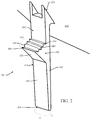
- FIG. 2 illustrates a perspective view of a second component having a retention device thereon that is capable of engagement with the cantilever snap to secure the first component to the second component according to an example embodiment.
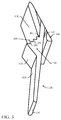
- FIG. 3 illustrates a perspective view of the first component and the second component joined together via engagement of the cantilever snap to the retention device according to an example embodiment.
- a cantilever snap 100 is shown disposed at a first component 110.
- the first component 110 and the cantilever snap 100 may each be formed of the same material (e.g., plastic).
- the cantilever snap 100 may be tooled or machined in the first component 110 such that the cantilever snap 100 and the first component 110 are integrally formed in the same unitary piece of material.
- the first component 110 may be provided and a surface of the first component 110 is generally visible in FIG. 1 .
- the first component 110 includes an orifice 120 that passes entirely through the surface of the first component 110.
- Two sidewalls 122 are formed in the first component to define sides of the orifice 120 (portions of only one of the sidewalls 122 are clearly shown in FIG. 1 ).
- a cantilevered-slant protrusion 130 may extend from the first component 110 through a portion of the orifice 120 and also extend over a substantial portion of the orifice 120.
- a width of the cantilevered-slant protrusion 130 may extend substantially between the sidewalls 122 and a length of the cantilevered-slant protrusion 130 may extend away from the surface of the first component 110 to cover a substantial portion of the orifice 120.
- the cantilevered-slant protrusion 130 may extend to form an angle (e.g., an acute angle) with the surface of the first component 110. In some embodiments, the angle may be between about 35 degrees and about 75 degrees).
- the cantilevered-slant protrusion 130 includes an engagement face 132 disposed at a distal end thereof.
- the engagement face 132 is disposed to substantially face toward an alignment rib 140 that is disposed to extend between the sidewalls 122 at a portion of the orifice 120 that is disposed opposite the portion of the orifice 120 from which the cantilevered-slant protrusion 130 extends.
- the alignment rib 140 extends from the same surface of the first component 110 from which the cantilevered-slant protrusion 130 extends.
- the alignment rib 140 defines an engagement surface 142 that extends substantially between the sidewalls and also extends substantially parallel to the direction of extension of the engagement face 132 of the cantilevered-slant protrusion 130.
- the engagement face 132 and the engagement surface 142 may be disposed to face each other and may each lie substantially within respective planes that lie substantially parallel to each other to define a reception area 150 capable of receiving a retention device as described in greater detail below.
- a distal end of the cantilevered-slant protrusion 130 e.g., proximate to the engagement face 132 may form a relatively sharp edge 152.
- FIG. 2 illustrates a retention device 200 of an example embodiment.
- the retention device 200 may be adjoined to a second component 210.
- the second component 210 and the retention device 200 may each be formed of the same material (e.g., plastic).
- the retention device 200 may be tooled, machined or molded in the second component 210 such that the retention device 200 and the second component 210 are integrally formed in the same unitary piece of material.
- the retention device 200 extends away from a surface of the second component 210 to form retention body 220.
- a length of the retention body 220 may be measured from a proximal end 222 that contacts the surface of the second component 210 to a distal end 224 that is farthest from the surface of the second component 210.
- the width (w) of the retention body 220 may be defined substantially as the width of a contact face 226 of the retention body 220 that extends along the length of the retention body 220 between lateral edges 228 of the retention body 220. In an example embodiment, the width (w) of the retention body 220 may remain constant over an entirety of the length of the retention body 220.
- a thickness (t) of the retention body 220 may be defined as a distance between the contact face 226 and a back face (not shown in FIG. 2 ) of the retention body 220.
- the thickness (t) of the retention body 220 may be defined by the width of the lateral edges 228.
- the thickness (t) may decrease as the retention body 220 extends from the proximal end 222 to the distal end 224 thereof.
- the thickness (t) may remain constant over the length of the retention body 220.
- the width (w) may vary along with the thickness (t).
- the retention body 220 includes a retaining extension 230.
- the retaining extension 230 may be disposed at a portion of the contact face 226 that is spaced apart from the surface of the second component 210.
- the distance by which the retaining extension 230 and the surface of the second component 210 are separated may be determined at least in part based on a thickness of the first component 110 and/or a degree of tightness that is desired for connecting the first and second components 110 and 210 together by insertion of the retention device 200 into the cantilever snap 100.
- the retaining extension 230 may extend past the edge 152 such that a portion of the retention body 220 that is between the proximal end 222 and the retaining extension may be held in the reception area 150.
- the retaining extension 230 may hold the retention body 220 in place relative to the cantilever snap 100 such that the first component 110 is held in relative close proximity and also relatively tightly to the second component 210.
- the retaining extension 230 may include a lead-in 232 and a holding assembly 240.
- the lead-in 232 may be a face that lies in a plane forming an angle with the contact face 260.
- the distal end 222 of the retention body 220 may be inserted into the orifice from a direction opposite of the direction at which the cantilevered-slant protrusion 130 and the alignment rib 140 extend away from the surface of the first component 110.
- the retention body 220 may move relatively freely as the distance between the edge 152 and the alignment rib 140 may be slightly larger than the thickness (t) of the retention body 220.
- the lead in 232 may gradually increase the apparent thickness of the retention body 220 in the region of the retaining extension 230 and the cantilevered-slant protrusion 130 may begin to be forced away from the alignment rib 140 as the retaining extension 230 is moved through the reception area 150.
- a thickness of the retention body 200 may, in some cases, be increased linearly over a length of the lead-in 232.
- the edge 152 may slide over the lead-in 232 and continue to extend a distance between the engagement face 132 and the engagement surface 142 as the thickness of the retention body 220 increases to a point of maximum thickness 250.
- the holding assembly 240 may engage the edge 152 to prevent movement of the retention body 220 back in the direction of insertion.
- the point of maximum thickness 250 may separate the holding assembly 240 and the lead-in 232.
- the holding assembly 240 may include teeth 242 configured to engage the edge 152 after the edge 152 passes over each respective one of the teeth 242 in order to prevent movement of the retention body 220 back in the direction of insertion.
- the teeth 242 may be arranged as a series of step-like protrusions and alternating valleys disposed on an incline relative to the contact face 226.
- the plane in which the teeth 242 lie (and therefore the plane along which the holding assembly 240 is arrayed) may be disposed at an angle relative to a plane of the retention body 220 (or the plane of the contact face 226).
- the teeth 242 may be arranged as a series of steps (as shown in FIGS.
- each step corresponds to one of the teeth 242 and each step includes one portion that provides a face that lies in a plane that is substantially perpendicular to the plane in which the contact face 226 lies, and another face that lies in a plane that is substantially parallel to the plane in which the contact face 226 lies.
- the edge 152 may simply slide past each face that lies in a plane that is substantially parallel to the plane in which the contact face 226 lies, and the face that lies in a plane that is substantially perpendicular to the plane in which the contact face 226 lies may prevent movement of the retention body 220 back in the direction of insertion.
- each tooth or step while being inclined at an angle relative to the contact face 226, is also a different distance from the proximal end 222.
- engagement of the edge 152 with each next step in the sequence as the proximal end 222 is approached actually draws the first component 110 closer to the second component 210 (for tighter engagement between the first and second components 110 and 210) while at the same time making it more difficult to release the engagement between the cantilever snap 100 and the retention device 200 since the edge 152 would have even more steps to clear in order to allow disengagement.
- the teeth 242 of the holding assembly 240 may allow the first component 110 and second component 210 to fit tightly together despite deviations in the snap portions and/or in the components arising out of the manufacturing process.
- embodiments of the invention may allow for greater tolerances.
- the snap could be designed so that the cantilevered-slant protrusion 130 engages the tooth or step 242 near the middle of the holding assembly 240 (i.e., approximately halfway between the point of maximum thickness 250 and the point where the holding assembly 240 meets the contact face 226).
- the cantilevered-slant protrusion 130 engages a tooth 242 closer to the point of maximum thickness 250, but the first component 110 and second component 210 are still held tightly together.
- the cantilevered-slant protrusion 130 engages a tooth 242 further from the point of maximum thickness 250, but the first component 110 and second component 210 are still held tightly together. Therefore, in some embodiments, the number of teeth 242 and/or the length of the holding assembly 240 can dictate certain tolerances.
- FIG. 3 illustrates the engagement between the cantilever snap 100 and the retention device 200 responsive to insertion of the retention device 200 into the cantilever snap 100.
- the retention body 220 of the retention device 200 is inserted into the orifice 120 of the cantilever snap 100.
- the orifice 120 includes sidewalls 122 and the cantilevered-slant protrusion 130 that extends between the sidewalls 122 and out of the orifice 120 at an angle relative to the surface of the first component 110 of which the cantilever snap 100 is an integral portion.
- the cantilevered-slant protrusion 130 faces the alignment rib 140 to define the space (e.g., the receiving area 150 of FIG. 1 ) into which the retention body 220 is placed.
- the alignment rib 140 faces the cantilevered-slant protrusion 130 to pinch the retention body 220 therebetween.
- the retention body 220 is inserted from a side opposite of the side of the first component 110 away from which the cantilevered-slant protrusion 130 extends and pulled through the space until a holding assembly 240 that lies in a plane that lies at an angle to the plane in which the retention body 220 lies.
- Example embodiments may therefore provide a mechanism by which to attach two components together using snap fittings that are integrally formed with the respective components. Moreover, some example embodiments may provide the cantilever portion (e.g., the cantilevered-slant protrusion 130) and an undercut (e.g., the retaining extension 230) on separate components, contrary to the design of many common cantilever snaps. Example embodiments may be used, for example, to join adjacent components or parts during the assembly of various types of devices including, as an example, outdoor power equipment such as lawn mowers. The joint formed may have a low insertion force requirement, but may provide for a very high removal force.
- the force may be funneled down the length of the retention body to create a moment on the top of the snap that would only tighten the fit.
- the step-like construction may provide an audible snap sound as each step is encountered so that assemblers may be able to audibly discern that the snap has been engaged.
- there are multiple possible levels of engagement e.g., corresponding to each step that can be sequentially engaged), so there is some flexibility in the spacing that can be provided between the components while still providing a secure fit.
- Each of the multiples levels of engagement may correspond to respective ones of a series of step-like protrusions that each defines a discrete holding point at which the retention body 220 may be held.
- Each discrete holding point may be a corresponding different distance from a distal end 224 of the retention body 220.
Landscapes
- Engineering & Computer Science (AREA)
- General Engineering & Computer Science (AREA)
- Mechanical Engineering (AREA)
- Snaps, Bayonet Connections, Set Pins, And Snap Rings (AREA)
- Connection Of Plates (AREA)
- Buckles (AREA)
Description
- Example embodiments generally relate to mechanisms for joining components and, more particularly, relate to a snap feature that may be utilized to join two components securely with a relatively low insertion force.
- During assembly of many products, particularly those that employ plastic components, it is necessary to secure adjacent parts to each other. As an example, during assembly of outdoor power equipment such as a riding lawn mower, there may be a number of body panels that may need to be secured to each other, the frame and/or other components.
- Joining of components may typically be performed using hardware (e.g., metal clasps, snaps or buckles that join adjacent plastic pieces) or plastic snaps. Although hardware can often provide secure joints and may be relatively easy to employ, the use of hardware increases the number of components since the hardware is actually separate from the plastic components being joined and must be separately produced and then may also take more effort in assembly. Plastic snaps, which may employ a conventional cantilever snap design, may require varying amounts of force to install since it is typical for the amount of install force of a plastic snap to increase with the stiffness of the material and the desired amount of engagement. As such, where a great deal of holding power is desired, a plastic snap that requires a lot of force and is difficult to install must typically be used. Moreover, in many cases, the snap may require a corresponding hole or attachment feature that is large enough for the widest portion of the snap to fit through. Thus, the snap head can fit back through the hole and the two components may come apart.
- Furthermore, some snap designs require that the snap, hole, and components be manufactured with very small tolerances in order for the snap to hold the components together tightly. Sometimes deviations from these small tolerances can cause the snap to loosely fit in the hole (resulting in a loose fitting between the two components) or may prevent the snap from locking in the hole at all (preventing the joining of the two components at that snap location). Given some of the issues described above, it may be desirable to provide a snap feature that is capable of addressing at least some of these situations.
- The document
JP 2002 067974 A - Some example embodiments may provide a snap feature providing component attachment with a relatively low insertion force, but without a correspondingly low pullout force. In this regard, in some cases, a snap feature of an example embodiment may actually provide an extremely high pullout force. Accordingly, a snap feature according to an example embodiment may be used to join plastic components of outdoor power equipment such as a riding lawn care vehicle or other manufactured goods.
- In one example embodiment, a snap assembly is provided. The snap assembly includes a cantilever snap and a retention body. The cantilever snap includes an orifice defined in a surface of a first component. The orifice is defined between sidewalls. The cantilever snap further comprises a cantilevered-slant protrusion extending between the sidewalls and out of the orifice at an angle relative to the surface. The retention body is attached to a second component and configured to be inserted into the orifice from a side of the first component that is opposite of a side of the first component away from which the cantilevered-slant protrusion extends to secure the retention body to the cantilever snap. The retention body includes a retaining extension comprising a holding assembly that lies in a plane that lies at an angle to a plane in which the retention body lies.
- In some embodiments, the holding assembly comprises a plurality of teeth that are arrayed to form a series of step-like protrusions that sequentially step away from a contact face of the retention body. Each step-like protrusion is configured to engage with the cantilevered-slant protrusion to hold the retention body within the orifice. In this regard, each of the series of step-like protrusions defines a discrete holding point at which the retention body may be held, each discrete holding point being a corresponding different distance from a distal end of the retention body.
- Some example embodiments may improve the ability of manufacturers to facilitate easy, but secure assembly of manufactured goods having plastic components.
- Having thus described the invention in general terms, reference will now be made to the accompanying drawings, which are not necessarily drawn to scale, and wherein:
-
FIG. 1 illustrates a perspective view of a cantilever snap on a first component according to an example embodiment; -
FIG. 2 illustrates a perspective view of a second component having a retention device thereon that is capable of engagement with the cantilever snap to secure the first component to the second component according to an example embodiment; and -
FIG. 3 illustrates a perspective view of the first component and the second component joined together via engagement of the cantilever snap to the retention device according to an example embodiment. - Some example embodiments now will be described more fully hereinafter with reference to the accompanying drawings, in which some, but not all example embodiments are shown. Indeed, the examples described and pictured herein should not be construed as being limiting as to the scope, applicability or configuration of the present disclosure. Rather, these example embodiments are provided so that this disclosure will satisfy applicable legal requirements. Like reference numerals refer to like elements throughout. Furthermore, as used herein, the term "or" is to be interpreted as a logical operator that results in true whenever one or more of its operands are true. As used herein, operable coupling should be understood to relate to direct or indirect connection that, in either case, enables functional interconnection of components that are operably coupled to each other.
- An example embodiment will now be described in reference to
FIGS. 1-3 . In this regard,FIG. 1 illustrates a perspective view of a cantilever snap on a first component according to an example embodiment.FIG. 2 illustrates a perspective view of a second component having a retention device thereon that is capable of engagement with the cantilever snap to secure the first component to the second component according to an example embodiment.FIG. 3 illustrates a perspective view of the first component and the second component joined together via engagement of the cantilever snap to the retention device according to an example embodiment. - Referring first to
FIG. 1 , acantilever snap 100 is shown disposed at afirst component 110. In an example embodiment, thefirst component 110 and thecantilever snap 100 may each be formed of the same material (e.g., plastic). Moreover, in some cases, thecantilever snap 100 may be tooled or machined in thefirst component 110 such that thecantilever snap 100 and thefirst component 110 are integrally formed in the same unitary piece of material. - The
first component 110 may be provided and a surface of thefirst component 110 is generally visible inFIG. 1 . Thefirst component 110 includes anorifice 120 that
passes entirely through the surface of thefirst component 110. Twosidewalls 122 are formed in the first component to define sides of the orifice 120 (portions of only one of thesidewalls 122 are clearly shown inFIG. 1 ). In an example embodiment, a cantilevered-slant protrusion 130 may extend from thefirst component 110 through a portion of theorifice 120 and also extend over a substantial portion of theorifice 120. In this regard, for example, a width of the cantilevered-slant protrusion 130 may extend substantially between thesidewalls 122 and a length of the cantilevered-slant protrusion 130 may extend away from the surface of thefirst component 110 to cover a substantial portion of theorifice 120. As such, the cantilevered-slant protrusion 130 may extend to form an angle (e.g., an acute angle) with the surface of thefirst component 110. In some embodiments, the angle may be between about 35 degrees and about 75 degrees). - In an example embodiment, the cantilevered-
slant protrusion 130 includes anengagement face 132 disposed at a distal end thereof. Theengagement face 132 is disposed to substantially face toward analignment rib 140 that is disposed to extend
between thesidewalls 122 at a portion of theorifice 120 that is disposed opposite the portion of theorifice 120 from which the cantilevered-slant protrusion 130 extends. Thealignment rib 140 extends from the same surface of thefirst component 110 from which the cantilevered-slant protrusion 130 extends. Moreover, thealignment rib 140 defines anengagement surface 142 that extends substantially between the sidewalls and also extends substantially parallel to the direction of extension of theengagement face 132 of the cantilevered-slant protrusion 130. In some embodiments, theengagement face 132 and theengagement surface 142 may be disposed to face each other and may each lie substantially within respective planes that lie substantially parallel to each other to define areception area 150 capable of receiving a retention device as described in greater detail below. In some cases, a distal end of the cantilevered-slant protrusion 130 (e.g., proximate to the engagement face 132) may form a relativelysharp edge 152. -
FIG. 2 illustrates aretention device 200 of an example embodiment. Theretention device 200 may be adjoined to asecond component 210. In an example embodiment, thesecond component 210 and theretention device 200 may each be formed of the same material (e.g., plastic). Moreover, in some cases, theretention device 200 may be tooled, machined or molded in thesecond component 210 such that theretention device 200 and thesecond component 210 are integrally formed in the same unitary piece of material. - The
retention device 200 extends away from a surface of thesecond component 210 to formretention body 220. In an example embodiment, a length of theretention body 220 may be measured from aproximal end 222 that contacts the surface of thesecond component 210 to adistal end 224 that is farthest from the surface of thesecond component 210. The width (w) of theretention body 220 may be defined substantially as the width of acontact face 226 of theretention body 220 that extends along the length of theretention body 220 betweenlateral edges 228 of theretention body 220. In an example embodiment, the width (w) of theretention body 220 may remain constant over an entirety of the length of theretention body 220. A thickness (t) of theretention body 220 may be defined as a distance between thecontact face 226 and a back face (not shown inFIG. 2 ) of theretention body 220. In other words, the thickness (t) of theretention body 220 may be defined by the width of the lateral edges 228. In some embodiments, the thickness (t) may decrease as theretention body 220 extends from theproximal end 222 to thedistal end 224 thereof. However, in alternative embodiments, the thickness (t) may remain constant over the length of theretention body 220. Moreover, in some embodiments, the width (w) may vary along with the thickness (t). - In an example embodiment, the
retention body 220 includes a retainingextension 230. The retainingextension 230 may be disposed at a portion of thecontact face 226 that is spaced apart from the surface of thesecond component 210. In some embodiments, the distance by which the retainingextension 230 and the surface of thesecond component 210 are separated may be determined at least in part based on a thickness of thefirst component 110 and/or a degree of tightness that is desired for connecting the first andsecond components retention device 200 into thecantilever snap 100. When theretention device 200 is inserted into theorifice 120 of thecantilever snap 100 past the retainingextension 230, the retainingextension 230 may extend past theedge 152 such that a portion of theretention body 220 that is between theproximal end 222 and the retaining extension may be held in thereception area 150. The retainingextension 230 may hold theretention body 220 in place relative to thecantilever snap 100 such that thefirst component 110 is held in relative close proximity and also relatively tightly to thesecond component 210. - In some embodiments, the retaining
extension 230 may include a lead-in 232 and a holdingassembly 240. The lead-in 232 may be a face that lies in a plane forming an angle with the contact face 260. In an example embodiment, thedistal end 222 of theretention body 220 may be inserted into the orifice from a direction opposite of the direction at which the cantilevered-slant protrusion 130 and thealignment rib 140 extend away from the surface of thefirst component 110. As such, as thedistal end 222 is inserted into thereception area 150 and then theretention body 220 is advanced through thereception area 150 until theedge 152 reaches the lead-in 232, theretention body 220 may move relatively freely as the distance between theedge 152 and thealignment rib 140 may be slightly larger than the thickness (t) of theretention body 220. The lead in 232 may gradually increase the apparent thickness of theretention body 220 in the region of the retainingextension 230 and the cantilevered-slant protrusion 130 may begin to be forced away from thealignment rib 140 as the retainingextension 230 is moved through thereception area 150. In this regard, for example, a thickness of theretention body 200 may, in some cases, be increased linearly over a length of the lead-in 232. Because the lead-in 232 is slanted smoothly, theedge 152 may slide over the lead-in 232 and continue to extend a distance between theengagement face 132 and theengagement surface 142 as the thickness of theretention body 220 increases to a point ofmaximum thickness 250. After the point ofmaximum thickness 250, the holdingassembly 240 may engage theedge 152 to prevent movement of theretention body 220 back in the direction of insertion. Thus, the point ofmaximum thickness 250 may separate the holdingassembly 240 and the lead-in 232. - In an example embodiment, the holding
assembly 240 may includeteeth 242 configured to engage theedge 152 after theedge 152 passes over each respective one of theteeth 242 in order to prevent movement of theretention body 220 back in the direction of insertion. Theteeth 242 may be arranged as a series of step-like protrusions and alternating valleys disposed on an incline relative to thecontact face 226. As such, the plane in which theteeth 242 lie (and therefore the plane along which the holdingassembly 240 is arrayed) may be disposed at an angle relative to a plane of the retention body 220 (or the plane of the contact face 226). Although not required, in some embodiments, theteeth 242 may be arranged as a series of steps (as shown inFIGS. 2 and3 ) in which each step corresponds to one of theteeth 242 and each step includes one portion that provides a face that lies in a plane that is substantially perpendicular to the plane in which thecontact face 226 lies, and another face that lies in a plane that is substantially parallel to the plane in which thecontact face 226 lies. Thus, as theretention body 220 is pulled through thereception area 150 such that the cantilevered-slant protrusion 130 is deflected to allow passage of the lead in 232 through thereception area 150 until theedge 152 reaches the holdingassembly 240, theedge 152 may be enabled to pass over each sequential one of the steps that form theteeth 242. Theedge 152 may simply slide past each face that lies in a plane that is substantially parallel to the plane in which thecontact face 226 lies, and the face that lies in a plane that is substantially perpendicular to the plane in which thecontact face 226 lies may prevent movement of theretention body 220 back in the direction of insertion. - Of note, each tooth or step, while being inclined at an angle relative to the
contact face 226, is also a different distance from theproximal end 222. Thus, engagement of theedge 152 with each next step in the sequence as theproximal end 222 is approached actually draws thefirst component 110 closer to the second component 210 (for tighter engagement between the first andsecond components 110 and 210) while at the same time making it more difficult to release the engagement between thecantilever snap 100 and theretention device 200 since theedge 152 would have even more steps to clear in order to allow disengagement. In fact, in some situations, it may prove to be impractical or impossible to disengage thecantilever snap 100 and theretention device 200 after engagement without damaging or destroying them. - It will be appreciated that, in some embodiments, the
teeth 242 of the holdingassembly 240 may allow thefirst component 110 andsecond component 210 to fit tightly together despite deviations in the snap portions and/or in the components arising out of the manufacturing process. In other words, embodiments of the invention may allow for greater tolerances. For example, the snap could be designed so that the cantilevered-slant protrusion 130 engages the tooth or step 242 near the middle of the holding assembly 240 (i.e., approximately halfway between the point ofmaximum thickness 250 and the point where the holdingassembly 240 meets the contact face 226). Designed as such, if manufacturing of the components results in theretention body 220 not being able to be inserted through theorifice 120 as much as designed, then the cantilevered-slant protrusion 130 engages atooth 242 closer to the point ofmaximum thickness 250, but thefirst component 110 andsecond component 210 are still held tightly together. Likewise, if manufacturing of the components results in theretention body 220 being able to be inserted through theorifice 120 more than designed, then the cantilevered-slant protrusion 130 engages atooth 242 further from the point ofmaximum thickness 250, but thefirst component 110 andsecond component 210 are still held tightly together. Therefore, in some embodiments, the number ofteeth 242 and/or the length of the holdingassembly 240 can dictate certain tolerances. -
FIG. 3 illustrates the engagement between thecantilever snap 100 and theretention device 200 responsive to insertion of theretention device 200 into thecantilever snap 100. As can be seen inFIG. 3 , theretention body 220 of theretention device 200 is inserted into theorifice 120 of thecantilever snap 100. Theorifice 120 includessidewalls 122 and the cantilevered-slant protrusion 130 that extends between thesidewalls 122 and out of theorifice 120 at an angle relative to the surface of thefirst component 110 of which thecantilever snap 100 is an integral portion. The cantilevered-slant protrusion 130 faces thealignment rib 140 to define the space (e.g., the receivingarea 150 ofFIG. 1 ) into which theretention body 220 is placed. Thealignment rib 140 faces the cantilevered-slant protrusion 130 to pinch theretention body 220 therebetween. Theretention body 220 is inserted from a side opposite of the side of thefirst component 110 away from which the cantilevered-slant protrusion 130 extends and pulled through the space until a holdingassembly 240 that lies in a plane that lies at an angle to the plane in which theretention body 220 lies. - Example embodiments may therefore provide a mechanism by which to attach two components together using snap fittings that are integrally formed with the respective components. Moreover, some example embodiments may provide the cantilever portion (e.g., the cantilevered-slant protrusion 130) and an undercut (e.g., the retaining extension 230) on separate components, contrary to the design of many common cantilever snaps. Example embodiments may be used, for example, to join adjacent components or parts during the assembly of various types of devices including, as an example, outdoor power equipment such as lawn mowers. The joint formed may have a low insertion force requirement, but may provide for a very high removal force. In this regard, when one tries to pull the assembly apart, the force may be funneled down the length of the retention body to create a moment on the top of the snap that would only tighten the fit. Furthermore, the step-like construction may provide an audible snap sound as each step is encountered so that assemblers may be able to audibly discern that the snap has been engaged. Moreover, there are multiple possible levels of engagement (e.g., corresponding to each step that can be sequentially engaged), so there is some flexibility in the spacing that can be provided between the components while still providing a secure fit. Each of the multiples levels of engagement may correspond to respective ones of a series of step-like protrusions that each defines a discrete holding point at which the
retention body 220 may be held. Each discrete holding point may be a corresponding different distance from adistal end 224 of theretention body 220. - Many modifications and other embodiments of the inventions set forth herein will come to mind to one skilled in the art to which these inventions pertain having the benefit of the teachings presented in the foregoing descriptions and the associated drawings. Therefore, it is to be understood that the inventions are not to be limited to the specific embodiments disclosed and that modifications and other embodiments are intended to be included within the scope of the appended claims. Moreover, although the foregoing descriptions and the associated drawings describe exemplary embodiments in the context of certain exemplary combinations of elements and/or functions, it should be appreciated that different combinations of elements and/or functions may be provided by alternative embodiments without departing from the scope of the appended claims. In this regard, for example, different combinations of elements and/or functions than those explicitly described above are also contemplated as may be set forth in some of the appended claims. In cases where advantages, benefits or solutions to problems are described herein, it should be appreciated that such advantages, benefits and/or solutions may be applicable to some example embodiments, but not necessarily all example embodiments. Thus, any advantages, benefits or solutions described herein should not be thought of as being critical, required or essential to all embodiments or to that which is claimed herein. Although specific terms are employed herein, they are used in a generic and descriptive sense only and not for purposes of limitation.
Claims (15)
- A snap assembly comprising:a cantilever snap (100) including an orifice (120) defined in a surface of a first component (110), the orifice (120) being defined between side-walls (122), the cantilever snap (100) further comprising a cantilevered-slant protrusion (130) extending between the sidewalls (122) and out of the orifice (120) at an angle relative to the surface;
anda retention body (220) attached to a second component (210) and configured to be inserted into the orifice (120) from a side of the first component (110) that is opposite of a side of the first component (110) away from which the cantilevered-slant protrusion (130) extends to secure the retention body (220) to the cantilever snap (100), the retention body including a retaining extension (230) comprising a holding assembly (240) that lies in a plane that lies at an angle to a plane in which the retention body (220) lies,characterized in that
the cantilevered-slant protrusion (130) includes an engagement face (132) disposed at a distal end (224) thereof and disposed to substantially face toward an alignment rib (140) that is disposed opposite the portion of the orifice (120) from which the cantilevered-slant protrusion (130) extends
and
wherein the alignment rib (140) extends from the same surface of the first component (110) from which the cantilevered-slant protrusion (130) extends. - The snap assembly of claim 1, wherein the retaining extension (230) further comprises a lead-in (232) forming a slanted surface relative to a contact face (226) of the retention body (220), the contact face (226) contacting the cantilevered-slant protrusion (130) responsive to insertion of the retention body (220) into the orifice (120), the lead-in (232) slidably contacting the cantilevered-slant protrusion (130) responsive to insertion of the retention body (220) into the orifice (120).
- The snap assembly of claim 2, wherein the lead-in (232) is disposed proximate to the holding assembly (240), the lead-in (232) being closer to a distal end (224) of the retention body (220) than the holding assembly (240).
- The snap assembly of claim 2, wherein a thickness of the retention body (220) increases linearly over a length of the lead-in (232).
- The snap assembly of claim 4, wherein a point of maximum thickness of the retention body (220) separates the lead-in (232) from the holding assembly (240).
- The snap assembly of claim 1, wherein the holding assembly (240) comprises a plurality of teeth (242).
- The snap assembly of claim 6, wherein each tooth (242) of the plurality of teeth (242) includes a first portion that lies in a plane substantially perpendicular to a plane in which the retention body (220) lies and a second portion that lies in a plane substantially parallel to the plane in which the retention body (220) lies.
- The snap assembly of claim 6, wherein the plurality of teeth are arrayed to form a series of step-like protrusions that sequentially step away from a contact face (226) of the retention body (220).
- The snap assembly of claim 8, wherein each of the series of step-like protrusions defines a discrete holding point at which the retention body (220) may be held, each discrete holding point being a corresponding different distance from a distal end (224) of the retention body (220).
- The snap assembly of claim 8, wherein the cantilevered-slant protrusion (130) comprises an edge portion that engages a respective one of the step-like protrusions to prevent movement of the retention body (220) in a direction opposite a direction of insertion of the retention body (220) into the orifice (120).
- The snap assembly of claim 1, wherein the alignment rib (140) faces the cantilevered -slant protrusion (130) to pinch the retention body (220) there between.
- The snap assembly of claim 11, wherein the alignment rib (140) defines an engagement surface (142) that lies in a plane that is substantially parallel to a plane in which an engagement face (132) of the cantile-vered-slant protrusion (130) lies.
- The snap assembly of claim 1, wherein the cantilevered-slant protrusion (130) comprises an edge portion disposed proximate to the engagement face (132) to engage the holding assembly (240) to prevent movement of the retention body (220) in a direction opposite a direction of insertion of the retention body (220) into the orifice (120).
- The snap assembly of claim 1, wherein the first component (110) and the second component (210) are components of outdoor power equipment or
wherein the first component (110) and the second component (210) are components of a lawn mower. - The snap assembly of claim 1, wherein the first component (110) and the second component (210) are fixed to each other by insertion of the retention body (220) into the orifice (120) at least to a point at which the holding assembly (240) contacts the cantilevered-slant protrusion (130).
Applications Claiming Priority (1)
| Application Number | Priority Date | Filing Date | Title |
|---|---|---|---|
| PCT/US2011/045542 WO2013015804A1 (en) | 2011-07-27 | 2011-07-27 | Snap feature providing component attachment |
Publications (3)
| Publication Number | Publication Date |
|---|---|
| EP2737148A1 EP2737148A1 (en) | 2014-06-04 |
| EP2737148A4 EP2737148A4 (en) | 2015-01-28 |
| EP2737148B1 true EP2737148B1 (en) | 2016-11-02 |
Family
ID=47601412
Family Applications (1)
| Application Number | Title | Priority Date | Filing Date |
|---|---|---|---|
| EP11869995.8A Active EP2737148B1 (en) | 2011-07-27 | 2011-07-27 | Snap feature providing component attachment |
Country Status (5)
| Country | Link |
|---|---|
| US (1) | US9470025B2 (en) |
| EP (1) | EP2737148B1 (en) |
| CN (1) | CN103827425B (en) |
| AU (1) | AU2011373631B2 (en) |
| WO (1) | WO2013015804A1 (en) |
Families Citing this family (6)
| Publication number | Priority date | Publication date | Assignee | Title |
|---|---|---|---|---|
| US9676297B2 (en) | 2015-02-18 | 2017-06-13 | Ford Global Technologies, Llc | Cantilever snap tab attachment device |
| EP3566555B1 (en) * | 2017-01-05 | 2020-07-15 | Signify Holding B.V. | Attachment member and system |
| US10914513B1 (en) * | 2019-09-10 | 2021-02-09 | Whirlpool Corportion | Appliance mounting assembly |
| SE2250268A1 (en) * | 2022-02-28 | 2023-08-29 | Husqvarna Ab | Self-propelled Robotic Work Tool |
| CN114893479B (en) * | 2022-05-20 | 2024-08-02 | 四维尔丸井(广州)汽车零部件有限公司 | Universal buckle, appearance piece and manufacturing method of automobile decoration piece |
| DE102024106640B3 (en) * | 2024-03-07 | 2025-09-04 | Motherson Innovations Company Limited | HINGE AND/OR CLIP ARRANGEMENT, REARVIEW ARRANGEMENT AND VEHICLE |
Family Cites Families (24)
| Publication number | Priority date | Publication date | Assignee | Title |
|---|---|---|---|---|
| US2135417A (en) * | 1937-10-04 | 1938-11-01 | Albert H Tinnerman | Adapting sheet metal for receiving bolts, screws, or the like |
| US2326579A (en) * | 1940-03-25 | 1943-08-10 | Tinnerman Products Inc | Fastener |
| US2548838A (en) * | 1948-12-30 | 1951-04-10 | Borg Warner | Snap fastener |
| US3947932A (en) * | 1974-04-05 | 1976-04-06 | Gozlan Brothers Limited | Jewellery clasp |
| US4004734A (en) * | 1975-10-03 | 1977-01-25 | Airwick Industries, Inc. | Dispenser for air treating material |
| US4408914A (en) * | 1982-09-29 | 1983-10-11 | Teletype Corporation | Printer ribbon cartridge mounting assembly |
| US4636915A (en) * | 1985-08-20 | 1987-01-13 | Siemens Energy & Automation, Inc. | Fastener having dual teeth |
| US4844645A (en) | 1988-02-29 | 1989-07-04 | Hewlett-Packard Company | Locking system |
| US5577779A (en) * | 1994-12-22 | 1996-11-26 | Yazaki Corporation | Snap fit lock with release feature |
| FR2732731B1 (en) | 1995-04-06 | 1997-06-20 | Manducher Sa | INDEPENDENT ASSEMBLY BY LATCHING |
| EP0764788B1 (en) * | 1995-09-19 | 2001-09-12 | Daiwa Kasei Kogyo Kabushiki Kaisha | Component retaining legs |
| US6433559B1 (en) | 1997-05-16 | 2002-08-13 | Sc2N | Capacitive angle sensor, in particular for motor vehicle steering column |
| US5937867A (en) * | 1998-04-07 | 1999-08-17 | Williams; Ella J. | Hairpiece and method of using same |
| US6220637B1 (en) * | 1999-04-26 | 2001-04-24 | Motorola, Inc. | Snap fastener and interlocking tab |
| US6471313B1 (en) | 1999-12-13 | 2002-10-29 | Hoshizaki Denki Co., Ltd. | Corner cover mounting structure for heat-insulated housing for use in refrigerator |
| JP3698624B2 (en) * | 2000-08-25 | 2005-09-21 | ビステオン・ジャパン株式会社 | Mating structure of resin molded products for vehicles |
| JP2003222113A (en) * | 2002-01-29 | 2003-08-08 | Nippon Pop Rivets & Fasteners Ltd | clip |
| DE20204674U1 (en) | 2002-03-23 | 2003-08-07 | fischerwerke Artur Fischer GmbH & Co. KG, 72178 Waldachtal | System for fitting sink in worktop comprises mounting which fits over lower edge of cut-out and fixing attached to sink which has serrated strip whose teeth cooperate with corresponding teeth inside mounting |
| JP4211713B2 (en) | 2003-09-05 | 2009-01-21 | トヨタ紡織株式会社 | Bond structure |
| JP2007174887A (en) * | 2005-11-24 | 2007-07-05 | Daiwa Kasei Ind Co Ltd | Fastener |
| CN200955537Y (en) * | 2006-09-30 | 2007-10-03 | 陈健雄 | Combined connection member with single-direction fastening structure |
| US7950186B2 (en) | 2006-11-09 | 2011-05-31 | Cooper-Standard Automotive Inc. | Clip-on inner panel seal assembly |
| US20090087279A1 (en) * | 2007-09-28 | 2009-04-02 | Kevton, Llc | Quick Connection Device |
| CN101440837A (en) * | 2007-11-25 | 2009-05-27 | 刘齐 | Wedge-shaped concave-convex clutch buckle |
-
2011
- 2011-07-27 AU AU2011373631A patent/AU2011373631B2/en active Active
- 2011-07-27 EP EP11869995.8A patent/EP2737148B1/en active Active
- 2011-07-27 CN CN201180073704.6A patent/CN103827425B/en active Active
- 2011-07-27 WO PCT/US2011/045542 patent/WO2013015804A1/en not_active Ceased
- 2011-07-27 US US14/234,273 patent/US9470025B2/en active Active
Also Published As
| Publication number | Publication date |
|---|---|
| AU2011373631A1 (en) | 2014-02-13 |
| US20140159382A1 (en) | 2014-06-12 |
| EP2737148A1 (en) | 2014-06-04 |
| US9470025B2 (en) | 2016-10-18 |
| EP2737148A4 (en) | 2015-01-28 |
| AU2011373631B2 (en) | 2014-03-13 |
| CN103827425A (en) | 2014-05-28 |
| CN103827425B (en) | 2016-12-28 |
| WO2013015804A1 (en) | 2013-01-31 |
Similar Documents
| Publication | Publication Date | Title |
|---|---|---|
| US9470025B2 (en) | Snap feature providing component attachment | |
| US9220323B2 (en) | Slider provided with handle at rear for slide fastener | |
| EP2460394B1 (en) | Housing with locking structure | |
| KR101245498B1 (en) | Slider for slide fastener with automatic stopper | |
| EP2530028A1 (en) | Belt clamp | |
| US20140208561A1 (en) | Elastic alignment assembly for aligning mated components and method of reducing postional variation | |
| US20140300130A1 (en) | Elastic retaining arrangement for jointed components and method of reducing a gap between jointed components | |
| JP5714317B2 (en) | Spring clip | |
| US8051539B2 (en) | Blade fastener for trim member | |
| KR20150067075A (en) | Fixing device for cables | |
| US7638712B2 (en) | Protector | |
| US20150061475A1 (en) | Latch system | |
| JP5019115B2 (en) | Slide fastener with bottom fastener for slide fastener and slide fastener | |
| US20190037973A1 (en) | Buckle | |
| JP2018071750A (en) | Vehicular fixing component | |
| CN103211358B (en) | A kind of upper only assembly of fast de-slide fastener | |
| US20190264725A1 (en) | Removable push-on fastener | |
| WO2017060334A1 (en) | Connector | |
| JP5199159B2 (en) | Belt profile and belt with profile | |
| JP6294610B2 (en) | Resin clip | |
| JP2004263791A (en) | Clip | |
| US11746809B2 (en) | Connection device for interconnecting two components made of plastics material | |
| US20140020216A1 (en) | Zipper Insertion-Pin Structure | |
| KR101866307B1 (en) | Fixing Structure of Combination member for Vehicle | |
| WO2022118404A1 (en) | Zipper slider |
Legal Events
| Date | Code | Title | Description |
|---|---|---|---|
| PUAI | Public reference made under article 153(3) epc to a published international application that has entered the european phase |
Free format text: ORIGINAL CODE: 0009012 |
|
| 17P | Request for examination filed |
Effective date: 20140217 |
|
| AK | Designated contracting states |
Kind code of ref document: A1 Designated state(s): AL AT BE BG CH CY CZ DE DK EE ES FI FR GB GR HR HU IE IS IT LI LT LU LV MC MK MT NL NO PL PT RO RS SE SI SK SM TR |
|
| DAX | Request for extension of the european patent (deleted) | ||
| A4 | Supplementary search report drawn up and despatched |
Effective date: 20150109 |
|
| RIC1 | Information provided on ipc code assigned before grant |
Ipc: E05C 19/06 20060101AFI20141223BHEP Ipc: F16B 21/08 20060101ALI20141223BHEP Ipc: F16B 21/07 20060101ALI20141223BHEP Ipc: F16B 5/06 20060101ALI20141223BHEP |
|
| RAP1 | Party data changed (applicant data changed or rights of an application transferred) |
Owner name: HUSQVARNA AB |
|
| RAP1 | Party data changed (applicant data changed or rights of an application transferred) |
Owner name: HUSQVARNA AB |
|
| 17Q | First examination report despatched |
Effective date: 20151104 |
|
| GRAP | Despatch of communication of intention to grant a patent |
Free format text: ORIGINAL CODE: EPIDOSNIGR1 |
|
| INTG | Intention to grant announced |
Effective date: 20160519 |
|
| RIN1 | Information on inventor provided before grant (corrected) |
Inventor name: SOUTHWELL, JOHN Inventor name: CANONGE, ERIC |
|
| GRAS | Grant fee paid |
Free format text: ORIGINAL CODE: EPIDOSNIGR3 |
|
| GRAA | (expected) grant |
Free format text: ORIGINAL CODE: 0009210 |
|
| AK | Designated contracting states |
Kind code of ref document: B1 Designated state(s): AL AT BE BG CH CY CZ DE DK EE ES FI FR GB GR HR HU IE IS IT LI LT LU LV MC MK MT NL NO PL PT RO RS SE SI SK SM TR |
|
| REG | Reference to a national code |
Ref country code: GB Ref legal event code: FG4D |
|
| REG | Reference to a national code |
Ref country code: AT Ref legal event code: REF Ref document number: 842034 Country of ref document: AT Kind code of ref document: T Effective date: 20161115 Ref country code: CH Ref legal event code: EP |
|
| REG | Reference to a national code |
Ref country code: IE Ref legal event code: FG4D |
|
| REG | Reference to a national code |
Ref country code: DE Ref legal event code: R096 Ref document number: 602011032074 Country of ref document: DE |
|
| PG25 | Lapsed in a contracting state [announced via postgrant information from national office to epo] |
Ref country code: LV Free format text: LAPSE BECAUSE OF FAILURE TO SUBMIT A TRANSLATION OF THE DESCRIPTION OR TO PAY THE FEE WITHIN THE PRESCRIBED TIME-LIMIT Effective date: 20161102 |
|
| REG | Reference to a national code |
Ref country code: NL Ref legal event code: MP Effective date: 20161102 |
|
| REG | Reference to a national code |
Ref country code: LT Ref legal event code: MG4D |
|
| REG | Reference to a national code |
Ref country code: AT Ref legal event code: MK05 Ref document number: 842034 Country of ref document: AT Kind code of ref document: T Effective date: 20161102 |
|
| PG25 | Lapsed in a contracting state [announced via postgrant information from national office to epo] |
Ref country code: NO Free format text: LAPSE BECAUSE OF FAILURE TO SUBMIT A TRANSLATION OF THE DESCRIPTION OR TO PAY THE FEE WITHIN THE PRESCRIBED TIME-LIMIT Effective date: 20170202 Ref country code: GR Free format text: LAPSE BECAUSE OF FAILURE TO SUBMIT A TRANSLATION OF THE DESCRIPTION OR TO PAY THE FEE WITHIN THE PRESCRIBED TIME-LIMIT Effective date: 20170203 Ref country code: SE Free format text: LAPSE BECAUSE OF FAILURE TO SUBMIT A TRANSLATION OF THE DESCRIPTION OR TO PAY THE FEE WITHIN THE PRESCRIBED TIME-LIMIT Effective date: 20161102 Ref country code: NL Free format text: LAPSE BECAUSE OF FAILURE TO SUBMIT A TRANSLATION OF THE DESCRIPTION OR TO PAY THE FEE WITHIN THE PRESCRIBED TIME-LIMIT Effective date: 20161102 Ref country code: LT Free format text: LAPSE BECAUSE OF FAILURE TO SUBMIT A TRANSLATION OF THE DESCRIPTION OR TO PAY THE FEE WITHIN THE PRESCRIBED TIME-LIMIT Effective date: 20161102 |
|
| PG25 | Lapsed in a contracting state [announced via postgrant information from national office to epo] |
Ref country code: FI Free format text: LAPSE BECAUSE OF FAILURE TO SUBMIT A TRANSLATION OF THE DESCRIPTION OR TO PAY THE FEE WITHIN THE PRESCRIBED TIME-LIMIT Effective date: 20161102 Ref country code: RS Free format text: LAPSE BECAUSE OF FAILURE TO SUBMIT A TRANSLATION OF THE DESCRIPTION OR TO PAY THE FEE WITHIN THE PRESCRIBED TIME-LIMIT Effective date: 20161102 Ref country code: HR Free format text: LAPSE BECAUSE OF FAILURE TO SUBMIT A TRANSLATION OF THE DESCRIPTION OR TO PAY THE FEE WITHIN THE PRESCRIBED TIME-LIMIT Effective date: 20161102 Ref country code: AT Free format text: LAPSE BECAUSE OF FAILURE TO SUBMIT A TRANSLATION OF THE DESCRIPTION OR TO PAY THE FEE WITHIN THE PRESCRIBED TIME-LIMIT Effective date: 20161102 Ref country code: PT Free format text: LAPSE BECAUSE OF FAILURE TO SUBMIT A TRANSLATION OF THE DESCRIPTION OR TO PAY THE FEE WITHIN THE PRESCRIBED TIME-LIMIT Effective date: 20170302 Ref country code: ES Free format text: LAPSE BECAUSE OF FAILURE TO SUBMIT A TRANSLATION OF THE DESCRIPTION OR TO PAY THE FEE WITHIN THE PRESCRIBED TIME-LIMIT Effective date: 20161102 Ref country code: IS Free format text: LAPSE BECAUSE OF FAILURE TO SUBMIT A TRANSLATION OF THE DESCRIPTION OR TO PAY THE FEE WITHIN THE PRESCRIBED TIME-LIMIT Effective date: 20170302 Ref country code: PL Free format text: LAPSE BECAUSE OF FAILURE TO SUBMIT A TRANSLATION OF THE DESCRIPTION OR TO PAY THE FEE WITHIN THE PRESCRIBED TIME-LIMIT Effective date: 20161102 |
|
| REG | Reference to a national code |
Ref country code: FR Ref legal event code: PLFP Year of fee payment: 7 |
|
| PG25 | Lapsed in a contracting state [announced via postgrant information from national office to epo] |
Ref country code: EE Free format text: LAPSE BECAUSE OF FAILURE TO SUBMIT A TRANSLATION OF THE DESCRIPTION OR TO PAY THE FEE WITHIN THE PRESCRIBED TIME-LIMIT Effective date: 20161102 Ref country code: CZ Free format text: LAPSE BECAUSE OF FAILURE TO SUBMIT A TRANSLATION OF THE DESCRIPTION OR TO PAY THE FEE WITHIN THE PRESCRIBED TIME-LIMIT Effective date: 20161102 Ref country code: RO Free format text: LAPSE BECAUSE OF FAILURE TO SUBMIT A TRANSLATION OF THE DESCRIPTION OR TO PAY THE FEE WITHIN THE PRESCRIBED TIME-LIMIT Effective date: 20161102 Ref country code: SK Free format text: LAPSE BECAUSE OF FAILURE TO SUBMIT A TRANSLATION OF THE DESCRIPTION OR TO PAY THE FEE WITHIN THE PRESCRIBED TIME-LIMIT Effective date: 20161102 Ref country code: DK Free format text: LAPSE BECAUSE OF FAILURE TO SUBMIT A TRANSLATION OF THE DESCRIPTION OR TO PAY THE FEE WITHIN THE PRESCRIBED TIME-LIMIT Effective date: 20161102 |
|
| REG | Reference to a national code |
Ref country code: DE Ref legal event code: R097 Ref document number: 602011032074 Country of ref document: DE |
|
| PG25 | Lapsed in a contracting state [announced via postgrant information from national office to epo] |
Ref country code: IT Free format text: LAPSE BECAUSE OF FAILURE TO SUBMIT A TRANSLATION OF THE DESCRIPTION OR TO PAY THE FEE WITHIN THE PRESCRIBED TIME-LIMIT Effective date: 20161102 Ref country code: SM Free format text: LAPSE BECAUSE OF FAILURE TO SUBMIT A TRANSLATION OF THE DESCRIPTION OR TO PAY THE FEE WITHIN THE PRESCRIBED TIME-LIMIT Effective date: 20161102 Ref country code: BG Free format text: LAPSE BECAUSE OF FAILURE TO SUBMIT A TRANSLATION OF THE DESCRIPTION OR TO PAY THE FEE WITHIN THE PRESCRIBED TIME-LIMIT Effective date: 20170202 Ref country code: BE Free format text: LAPSE BECAUSE OF FAILURE TO SUBMIT A TRANSLATION OF THE DESCRIPTION OR TO PAY THE FEE WITHIN THE PRESCRIBED TIME-LIMIT Effective date: 20161102 |
|
| PLBE | No opposition filed within time limit |
Free format text: ORIGINAL CODE: 0009261 |
|
| STAA | Information on the status of an ep patent application or granted ep patent |
Free format text: STATUS: NO OPPOSITION FILED WITHIN TIME LIMIT |
|
| 26N | No opposition filed |
Effective date: 20170803 |
|
| PG25 | Lapsed in a contracting state [announced via postgrant information from national office to epo] |
Ref country code: SI Free format text: LAPSE BECAUSE OF FAILURE TO SUBMIT A TRANSLATION OF THE DESCRIPTION OR TO PAY THE FEE WITHIN THE PRESCRIBED TIME-LIMIT Effective date: 20161102 |
|
| REG | Reference to a national code |
Ref country code: CH Ref legal event code: PL |
|
| GBPC | Gb: european patent ceased through non-payment of renewal fee |
Effective date: 20170727 |
|
| REG | Reference to a national code |
Ref country code: IE Ref legal event code: MM4A |
|
| PG25 | Lapsed in a contracting state [announced via postgrant information from national office to epo] |
Ref country code: IE Free format text: LAPSE BECAUSE OF NON-PAYMENT OF DUE FEES Effective date: 20170727 Ref country code: LI Free format text: LAPSE BECAUSE OF NON-PAYMENT OF DUE FEES Effective date: 20170731 Ref country code: CH Free format text: LAPSE BECAUSE OF NON-PAYMENT OF DUE FEES Effective date: 20170731 Ref country code: GB Free format text: LAPSE BECAUSE OF NON-PAYMENT OF DUE FEES Effective date: 20170727 |
|
| REG | Reference to a national code |
Ref country code: FR Ref legal event code: PLFP Year of fee payment: 8 |
|
| PG25 | Lapsed in a contracting state [announced via postgrant information from national office to epo] |
Ref country code: LU Free format text: LAPSE BECAUSE OF NON-PAYMENT OF DUE FEES Effective date: 20170727 |
|
| PG25 | Lapsed in a contracting state [announced via postgrant information from national office to epo] |
Ref country code: MT Free format text: LAPSE BECAUSE OF NON-PAYMENT OF DUE FEES Effective date: 20170727 |
|
| PG25 | Lapsed in a contracting state [announced via postgrant information from national office to epo] |
Ref country code: MC Free format text: LAPSE BECAUSE OF FAILURE TO SUBMIT A TRANSLATION OF THE DESCRIPTION OR TO PAY THE FEE WITHIN THE PRESCRIBED TIME-LIMIT Effective date: 20161102 Ref country code: HU Free format text: LAPSE BECAUSE OF FAILURE TO SUBMIT A TRANSLATION OF THE DESCRIPTION OR TO PAY THE FEE WITHIN THE PRESCRIBED TIME-LIMIT; INVALID AB INITIO Effective date: 20110727 |
|
| PG25 | Lapsed in a contracting state [announced via postgrant information from national office to epo] |
Ref country code: CY Free format text: LAPSE BECAUSE OF NON-PAYMENT OF DUE FEES Effective date: 20161102 |
|
| PG25 | Lapsed in a contracting state [announced via postgrant information from national office to epo] |
Ref country code: MK Free format text: LAPSE BECAUSE OF FAILURE TO SUBMIT A TRANSLATION OF THE DESCRIPTION OR TO PAY THE FEE WITHIN THE PRESCRIBED TIME-LIMIT Effective date: 20161102 |
|
| PG25 | Lapsed in a contracting state [announced via postgrant information from national office to epo] |
Ref country code: TR Free format text: LAPSE BECAUSE OF FAILURE TO SUBMIT A TRANSLATION OF THE DESCRIPTION OR TO PAY THE FEE WITHIN THE PRESCRIBED TIME-LIMIT Effective date: 20161102 |
|
| PG25 | Lapsed in a contracting state [announced via postgrant information from national office to epo] |
Ref country code: AL Free format text: LAPSE BECAUSE OF FAILURE TO SUBMIT A TRANSLATION OF THE DESCRIPTION OR TO PAY THE FEE WITHIN THE PRESCRIBED TIME-LIMIT Effective date: 20161102 |
|
| P01 | Opt-out of the competence of the unified patent court (upc) registered |
Effective date: 20230419 |
|
| PGFP | Annual fee paid to national office [announced via postgrant information from national office to epo] |
Ref country code: DE Payment date: 20250603 Year of fee payment: 15 |
|
| PGFP | Annual fee paid to national office [announced via postgrant information from national office to epo] |
Ref country code: FR Payment date: 20260612 Year of fee payment: 16 |