EP2736471B1 - Tampon having a hollow space - Google Patents
Tampon having a hollow space Download PDFInfo
- Publication number
- EP2736471B1 EP2736471B1 EP12735919.8A EP12735919A EP2736471B1 EP 2736471 B1 EP2736471 B1 EP 2736471B1 EP 12735919 A EP12735919 A EP 12735919A EP 2736471 B1 EP2736471 B1 EP 2736471B1
- Authority
- EP
- European Patent Office
- Prior art keywords
- tampon
- hollow body
- capsule
- absorbent material
- sleeve
- Prior art date
- Legal status (The legal status is an assumption and is not a legal conclusion. Google has not performed a legal analysis and makes no representation as to the accuracy of the status listed.)
- Active
Links
Images

Classifications
-
- A—HUMAN NECESSITIES
- A61—MEDICAL OR VETERINARY SCIENCE; HYGIENE
- A61F—FILTERS IMPLANTABLE INTO BLOOD VESSELS; PROSTHESES; DEVICES PROVIDING PATENCY TO, OR PREVENTING COLLAPSING OF, TUBULAR STRUCTURES OF THE BODY, e.g. STENTS; ORTHOPAEDIC, NURSING OR CONTRACEPTIVE DEVICES; FOMENTATION; TREATMENT OR PROTECTION OF EYES OR EARS; BANDAGES, DRESSINGS OR ABSORBENT PADS; FIRST-AID KITS
- A61F13/00—Bandages or dressings; Absorbent pads
- A61F13/15—Absorbent pads, e.g. sanitary towels, swabs or tampons for external or internal application to the body; Supporting or fastening means therefor; Tampon applicators
- A61F13/20—Tampons, e.g. catamenial tampons; Accessories therefor
- A61F13/2022—Tampons, e.g. catamenial tampons; Accessories therefor characterised by the shape
- A61F13/2042—Tampons, e.g. catamenial tampons; Accessories therefor characterised by the shape having a central tubular opening
-
- A—HUMAN NECESSITIES
- A61—MEDICAL OR VETERINARY SCIENCE; HYGIENE
- A61F—FILTERS IMPLANTABLE INTO BLOOD VESSELS; PROSTHESES; DEVICES PROVIDING PATENCY TO, OR PREVENTING COLLAPSING OF, TUBULAR STRUCTURES OF THE BODY, e.g. STENTS; ORTHOPAEDIC, NURSING OR CONTRACEPTIVE DEVICES; FOMENTATION; TREATMENT OR PROTECTION OF EYES OR EARS; BANDAGES, DRESSINGS OR ABSORBENT PADS; FIRST-AID KITS
- A61F13/00—Bandages or dressings; Absorbent pads
- A61F13/15—Absorbent pads, e.g. sanitary towels, swabs or tampons for external or internal application to the body; Supporting or fastening means therefor; Tampon applicators
- A61F13/20—Tampons, e.g. catamenial tampons; Accessories therefor
- A61F13/2051—Tampons, e.g. catamenial tampons; Accessories therefor characterised by the material or the structure of the inner absorbing core
-
- A—HUMAN NECESSITIES
- A61—MEDICAL OR VETERINARY SCIENCE; HYGIENE
- A61F—FILTERS IMPLANTABLE INTO BLOOD VESSELS; PROSTHESES; DEVICES PROVIDING PATENCY TO, OR PREVENTING COLLAPSING OF, TUBULAR STRUCTURES OF THE BODY, e.g. STENTS; ORTHOPAEDIC, NURSING OR CONTRACEPTIVE DEVICES; FOMENTATION; TREATMENT OR PROTECTION OF EYES OR EARS; BANDAGES, DRESSINGS OR ABSORBENT PADS; FIRST-AID KITS
- A61F13/00—Bandages or dressings; Absorbent pads
- A61F13/15—Absorbent pads, e.g. sanitary towels, swabs or tampons for external or internal application to the body; Supporting or fastening means therefor; Tampon applicators
- A61F13/20—Tampons, e.g. catamenial tampons; Accessories therefor
- A61F13/2074—Tampons, e.g. catamenial tampons; Accessories therefor impregnated with hydrophobic, hydrophilic, skin enhancers, medicinal etc. substances
-
- A—HUMAN NECESSITIES
- A61—MEDICAL OR VETERINARY SCIENCE; HYGIENE
- A61F—FILTERS IMPLANTABLE INTO BLOOD VESSELS; PROSTHESES; DEVICES PROVIDING PATENCY TO, OR PREVENTING COLLAPSING OF, TUBULAR STRUCTURES OF THE BODY, e.g. STENTS; ORTHOPAEDIC, NURSING OR CONTRACEPTIVE DEVICES; FOMENTATION; TREATMENT OR PROTECTION OF EYES OR EARS; BANDAGES, DRESSINGS OR ABSORBENT PADS; FIRST-AID KITS
- A61F13/00—Bandages or dressings; Absorbent pads
- A61F13/15—Absorbent pads, e.g. sanitary towels, swabs or tampons for external or internal application to the body; Supporting or fastening means therefor; Tampon applicators
- A61F13/20—Tampons, e.g. catamenial tampons; Accessories therefor
- A61F13/34—Means for withdrawing tampons, e.g. withdrawal strings
-
- A—HUMAN NECESSITIES
- A61—MEDICAL OR VETERINARY SCIENCE; HYGIENE
- A61K—PREPARATIONS FOR MEDICAL, DENTAL OR TOILETRY PURPOSES
- A61K9/00—Medicinal preparations characterised by special physical form
- A61K9/0012—Galenical forms characterised by the site of application
- A61K9/0034—Urogenital system, e.g. vagina, uterus, cervix, penis, scrotum, urethra, bladder; Personal lubricants
- A61K9/0036—Devices retained in the vagina or cervix for a prolonged period, e.g. intravaginal rings, medicated tampons, medicated diaphragms
-
- A—HUMAN NECESSITIES
- A61—MEDICAL OR VETERINARY SCIENCE; HYGIENE
- A61H—PHYSICAL THERAPY APPARATUS, e.g. DEVICES FOR LOCATING OR STIMULATING REFLEX POINTS IN THE BODY; ARTIFICIAL RESPIRATION; MASSAGE; BATHING DEVICES FOR SPECIAL THERAPEUTIC OR HYGIENIC PURPOSES OR SPECIFIC PARTS OF THE BODY
- A61H19/00—Massage for the genitals; Devices for improving sexual intercourse
- A61H19/40—Devices insertable in the genitals
- A61H19/44—Having substantially cylindrical shape, e.g. dildos
-
- A—HUMAN NECESSITIES
- A61—MEDICAL OR VETERINARY SCIENCE; HYGIENE
- A61H—PHYSICAL THERAPY APPARATUS, e.g. DEVICES FOR LOCATING OR STIMULATING REFLEX POINTS IN THE BODY; ARTIFICIAL RESPIRATION; MASSAGE; BATHING DEVICES FOR SPECIAL THERAPEUTIC OR HYGIENIC PURPOSES OR SPECIFIC PARTS OF THE BODY
- A61H2201/00—Characteristics of apparatus not provided for in the preceding codes
- A61H2201/01—Constructive details
- A61H2201/0107—Constructive details modular
-
- A—HUMAN NECESSITIES
- A61—MEDICAL OR VETERINARY SCIENCE; HYGIENE
- A61H—PHYSICAL THERAPY APPARATUS, e.g. DEVICES FOR LOCATING OR STIMULATING REFLEX POINTS IN THE BODY; ARTIFICIAL RESPIRATION; MASSAGE; BATHING DEVICES FOR SPECIAL THERAPEUTIC OR HYGIENIC PURPOSES OR SPECIFIC PARTS OF THE BODY
- A61H23/00—Percussion or vibration massage, e.g. using supersonic vibration; Suction-vibration massage; Massage with moving diaphragms
- A61H23/02—Percussion or vibration massage, e.g. using supersonic vibration; Suction-vibration massage; Massage with moving diaphragms with electric or magnetic drive
Definitions
- the invention relates to a tampon of an absorbent material that has a hollow space for receiving a capsule.
- tampon assemblies having a vibration element embedded in the tampon body are known in the art. Tampon assemblies of this kind are used to relieve menstrual problems.
- the embedding of the vibration element in the tampon body it follows from US2007/0260210 only that the vibration element is contained in a capsule on the exterior of which retaining elements are arranged in order to prevent that the capsule is pulled out of the tampon body particularly when the assembly is retracted from the vagina.
- the tampon body is described as an absorbent body having a hollow space into which the capsule is apparently inserted.
- neither the construction of this tampon body nor its manufacture are described in the cited references.
- the invention is based upon the object of suggesting a tampon having a hollow space for receiving a capsule that is simple and inexpensive to manufacture.
- capsule shall not be limited to a vibration element.
- the hollow space is formed by a hollow body that is surrounded by absorbent material on at least part of its length.
- this solution offers the advantage that the hollow body can be prefabricated and covered, e.g. wrapped, with the absorbent material.
- the absorbent material may e.g. be a fibrous material, but in the present context, the term is meant to include any material that is capable of and suitable for absorbing liquids, e.g. also a material having a foamy structure.
- the hollow body has retaining means for a capsule to be received in its interior. This allows a safe anchorage of this capsule in the tampon.
- the retaining means are designed as a circumferential groove arranged in the interior of the hollow body.
- a groove is simple to manufacture and is capable of receiving at least one projection provided on the circumference of the capsule.
- the retaining means are designed as at least one detent and the detent is arranged at the free end of a flexible tongue.
- the detent may engage the free end of a capsule or engage in a recess provided on the circumference of the capsule, e.g. an annular groove, and thus retain the capsule inside the tampon.
- the hollow body is provided with at least one anchoring element that is embedded in the absorbent material. In this manner it is reliably prevented that the hollow body may be pulled out of the absorbent material.
- the anchoring element has an elongated shape, is oriented at least approximately parallelly to the longitudinal axis of the hollow body, and is connected thereto in at least one end region of the hollow body.
- the hollow body has an apertured circumferential surface.
- This design in the manner of a cage allows incorporating more absorbent material than e.g. in a sleeve of the same outside dimensions having closed walls.
- the hollow body is provided with an antimicrobial substance at least on its inner surface.
- infections are thus prevented if a capsule used in the tampon has been insufficiently cleaned.
- the antimicrobial substance may e.g. be or contain silver and may be applied to the hollow body as a coating or incorporated in the material of the hollow body in the form of particles, e.g. nanoparticles.
- a further aspect of the invention relates to a device for removing a capsule contained in a tampon.
- This device comprises an element having an opening whose clear diameter at most corresponds to the clear diameter of the hollow body.
- the element has an open radial slot that extends from its opening. If a capsule provided with a pulling element is being used, e.g. a withdrawal string or a cable, this offers the advantage that the pulling element can be placed in this slot.
- the element has releasing means for displacing retaining means in the form of detents. This allows an easy and reliable removal of a capsule contained in the hollow space of the tampon. These releasing means are preferably designed as a conical sleeve. The latter pushes the detents outwards when the tampon is moved toward the conical sleeve.
- the device has a receptacle for receiving the tampon.
- the tampon need not be touched in order to remove the capsule and may be disposed of together with the receptacle.
- the receptacle consists of a sleeve that is closed on one side.
- a receptacle is particularly simple to manufacture.
- the sleeve is divided in the longitudinal direction and composed of two half-shells that are preferably connected by a hinge.
- a receptacle is particularly easy to handle.
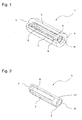
- Figure 1 shows a tampon 1 in a perspective view. It consists of an absorbent material 2 and has a rounded front end 3 and a rear end 4. Tampon 1 need not be cylindrical as depicted but may alternatively have a different longitudinal contour and a different cross-sectional shape. In the interior of absorbent material 2 a hollow body 5 is visible that is fastened in absorbent material 2 by means of an anchoring element 7. The function of anchoring element 7 will be explained in more detail hereinafter with reference to Figure 2 .
- Figure 2 shows hollow body 5 of Figure 1 without the surrounding absorbent material 2.
- the wall of hollow body 5 is provided with apertures 6 and may therefore also be described as a cage, and has a front end 9 and a rear end 10.
- the hollow body preferably consists of a synthetic material and is injection-molded.
- the rear end 10 of hollow body 5 is ring-shaped and its inner surface is provided with an annular groove 11 that serves as a retaining means for a capsule inserted in hollow body 5.
- the capsule may e.g. be a vibration element in the form of a capsule that is fastened in hollow body 5 by the retaining means.
- the capsule may be provided on its circumference with individual projections or a circumferential ridge that engages in annular groove 11.
- An anchoring element 7 is formed at the front end 9 of hollow body 5 which has a free end 8 and extends approximately parallelly to the longitudinal axis of hollow body 5.
- a strip of an absorbent material is introduced between anchoring element 7 and the circumferential surface of hollow body 5, similarly as in a pencil clip. Subsequently the absorbent material is wound around hollow body 5 and ultimately also covers anchoring element 7.
- anchoring element 7 may alternatively be designed in the manner of an eyelet, i.e. without free end 8.
- the completely wound up tampon may additionally be compacted as it is usual in tampon manufacture. To avoid that hollow body 5 is damaged in the process, the latter may receive a fitting mandrel during the compacting operation.
- a hollow body 5 that is apertured in the manner of a cage is used, a little more absorbent material may be incorporated due to the apertures than in a closed sleeve of the same external diameter. Furthermore, if a vibrator is used, the vibrations emanating therefrom are directly transmitted to the absorbent material through the apertures.
- Figure 3 shows an alternative embodiment of retaining means which are designed here as at least one detent 12 that is itself arranged at the free end of a flexible tongue 13.
- Reference numeral 14 denotes a capsule that is being retained inside hollow body 5 by detent 12 that engages its rear end wall.
- Capsule 14 has a withdrawal element 15 fastened thereto which serves for withdrawing a unit consisting of tampon 1 and capsule 14 e.g. from a body orifice.
- Figure 4 shows a device 16 for removing a capsule 14 from a tampon 1 of the kind described above.
- a disk-like element 17 has a central opening 18 through which capsule 14 fits. Furthermore, element 17 is provided with a radial slot 19 that is intended and dimensioned to receive the mentioned withdrawal element 15.
- capsule 14 is removed by inserting withdrawal element 15 in slot 19, retaining element 17, and then pulling on withdrawal element 15.
- the combination of annular groove 11 and of the mentioned projections or of the ridge, respectively, must be so designed that the force required for withdrawing capsule 14 from tampon 1 is significantly greater than the force required for withdrawing the tampon from a body orifice.
- element 17 has a cone 20 that is intended to displace detent 12 according to Figure 3 so as to release capsule 14 when the tampon is being moved toward cone 20 by pulling on withdrawal element 15.
- the device is preferably provided with a receptacle.
- the receptacle is composed of two half-shells 21, 22 that are connected by a film hinge 23, and element 17 is fastened to one 21 of the half-shells.
- tampon 1 is retained by the withdrawal element and placed in half-shell 21, and withdrawal element 15 is inserted in slot 19. Thereafter, a pull is exerted on withdrawal element 15 so that detents 12 enter into contact with cone 20 and as a result are forced outwards, thereby releasing capsule 14. The latter can now be withdrawn through opening 18.
- the half-shells Before or after pulling on withdrawal element 15, the half-shells can be closed and after removing capsule 14, the used tampon 1 can be disposed of together with device 16.
- FIGs 5a and 5b show an alternative embodiment of the device where the receptacle is designed as a sleeve 24 that is closed on one side.
- Element 17' is connected to sleeve 24 by means of a film hinge 30 so as to be insertable, after the introduction of a used tampon into the sleeve, in the open end of the latter where it is retained by the engagement of edge 28 in an annular groove 27.
- This device is additionally provided with a lid 25 that may be connected to sleeve 24 by a film hinge 29 and may be pushed over the open end of sleeve 24 after the removal of capsule 14, where it engages in an outer annular groove 26. In this manner, the receptacle is tightly closed for its disposal.
- a corresponding lid may also be provided in the example according to Figure 4 .
- Figure 5b shows that the latter is also provided with a slot 19' for receiving withdrawal element 15.
- Half-shells 21, 22 or sleeve 24 may e.g. consist of a synthetic material or of cardboard.
Landscapes
- Health & Medical Sciences (AREA)
- Life Sciences & Earth Sciences (AREA)
- Veterinary Medicine (AREA)
- Epidemiology (AREA)
- Public Health (AREA)
- General Health & Medical Sciences (AREA)
- Animal Behavior & Ethology (AREA)
- Biomedical Technology (AREA)
- Vascular Medicine (AREA)
- Heart & Thoracic Surgery (AREA)
- Engineering & Computer Science (AREA)
- Reproductive Health (AREA)
- Dermatology (AREA)
- Gynecology & Obstetrics (AREA)
- Urology & Nephrology (AREA)
- Chemical & Material Sciences (AREA)
- Medicinal Chemistry (AREA)
- Pharmacology & Pharmacy (AREA)
- Absorbent Articles And Supports Therefor (AREA)
Description
- The invention relates to a tampon of an absorbent material that has a hollow space for receiving a capsule.
- From references
US5782779 ,US6183428 , andUS2007/0260210 , tampon assemblies having a vibration element embedded in the tampon body are known in the art. Tampon assemblies of this kind are used to relieve menstrual problems. As to the embedding of the vibration element in the tampon body, it follows fromUS2007/0260210 only that the vibration element is contained in a capsule on the exterior of which retaining elements are arranged in order to prevent that the capsule is pulled out of the tampon body particularly when the assembly is retracted from the vagina. In this reference, the tampon body is described as an absorbent body having a hollow space into which the capsule is apparently inserted. However, neither the construction of this tampon body nor its manufacture are described in the cited references. - On the background of this prior art, the invention is based upon the object of suggesting a tampon having a hollow space for receiving a capsule that is simple and inexpensive to manufacture. In the context of the present invention, the term "capsule" shall not be limited to a vibration element.
- According to the invention, this object is attained in that the hollow space is formed by a hollow body that is surrounded by absorbent material on at least part of its length.
- In particular, this solution offers the advantage that the hollow body can be prefabricated and covered, e.g. wrapped, with the absorbent material. The absorbent material may e.g. be a fibrous material, but in the present context, the term is meant to include any material that is capable of and suitable for absorbing liquids, e.g. also a material having a foamy structure.
- According to one embodiment, the hollow body has retaining means for a capsule to be received in its interior. This allows a safe anchorage of this capsule in the tampon.
- According to a further embodiment, the retaining means are designed as a circumferential groove arranged in the interior of the hollow body. Such a groove is simple to manufacture and is capable of receiving at least one projection provided on the circumference of the capsule.
- According to other embodiments, the retaining means are designed as at least one detent and the detent is arranged at the free end of a flexible tongue. The detent may engage the free end of a capsule or engage in a recess provided on the circumference of the capsule, e.g. an annular groove, and thus retain the capsule inside the tampon.
- According to a further embodiment, the hollow body is provided with at least one anchoring element that is embedded in the absorbent material. In this manner it is reliably prevented that the hollow body may be pulled out of the absorbent material.
- According to a further embodiment, the anchoring element has an elongated shape, is oriented at least approximately parallelly to the longitudinal axis of the hollow body, and is connected thereto in at least one end region of the hollow body. This design allows a strip of an absorbent material to be retained between the circumference of the hollow body and the anchoring element and subsequently to wrap the absorbent material around the hollow body and the anchoring element in order to form a tampon.
- According to another embodiment the hollow body has an apertured circumferential surface. This design in the manner of a cage allows incorporating more absorbent material than e.g. in a sleeve of the same outside dimensions having closed walls.
- According to a particular embodiment, the hollow body is provided with an antimicrobial substance at least on its inner surface. In particular, infections are thus prevented if a capsule used in the tampon has been insufficiently cleaned. More specifically, the antimicrobial substance may e.g. be or contain silver and may be applied to the hollow body as a coating or incorporated in the material of the hollow body in the form of particles, e.g. nanoparticles.
- A further aspect of the invention relates to a device for removing a capsule contained in a tampon. This device comprises an element having an opening whose clear diameter at most corresponds to the clear diameter of the hollow body.
- These characteristic features offer the advantage that a capsule received in the tampon can be pulled out through the opening while the tampon is being retained by the element.
- According to one embodiment of the device, the element has an open radial slot that extends from its opening. If a capsule provided with a pulling element is being used, e.g. a withdrawal string or a cable, this offers the advantage that the pulling element can be placed in this slot. According to a further embodiment, the element has releasing means for displacing retaining means in the form of detents. This allows an easy and reliable removal of a capsule contained in the hollow space of the tampon. These releasing means are preferably designed as a conical sleeve. The latter pushes the detents outwards when the tampon is moved toward the conical sleeve.
- According to a further embodiment, the device has a receptacle for receiving the tampon. In this manner the tampon need not be touched in order to remove the capsule and may be disposed of together with the receptacle.
- According to a further embodiment, the receptacle consists of a sleeve that is closed on one side. Such a receptacle is particularly simple to manufacture.
- Ultimately, according to another embodiment, the sleeve is divided in the longitudinal direction and composed of two half-shells that are preferably connected by a hinge. Such a receptacle is particularly easy to handle.
- Exemplary embodiments of the invention will be explained by way of examples in more detail hereinafter with reference to the accompanying drawings showing
- Figure 1
- a partly cutaway perspective view of a tampon,
- Figure 2
- a perspective view of a hollow body,
- Figure 3
- a longitudinal section of a detail of another embodiment of a tampon having a capsule with a withdrawal element inserted in the hollow body,
- Figure 4
- a perspective view of a device for removing the capsule, and
- Figures 5a and 5b
- a sectional view of another device for removing the capsule.
-
Figure 1 shows atampon 1 in a perspective view. It consists of anabsorbent material 2 and has arounded front end 3 and arear end 4.Tampon 1 need not be cylindrical as depicted but may alternatively have a different longitudinal contour and a different cross-sectional shape. In the interior of absorbent material 2 ahollow body 5 is visible that is fastened inabsorbent material 2 by means of ananchoring element 7. The function of anchoringelement 7 will be explained in more detail hereinafter with reference toFigure 2 . -
Figure 2 showshollow body 5 ofFigure 1 without the surroundingabsorbent material 2. The wall ofhollow body 5 is provided withapertures 6 and may therefore also be described as a cage, and has afront end 9 and arear end 10. The hollow body preferably consists of a synthetic material and is injection-molded. In the example according toFigure 2 , therear end 10 ofhollow body 5 is ring-shaped and its inner surface is provided with anannular groove 11 that serves as a retaining means for a capsule inserted inhollow body 5. The capsule may e.g. be a vibration element in the form of a capsule that is fastened inhollow body 5 by the retaining means. To this end, the capsule may be provided on its circumference with individual projections or a circumferential ridge that engages inannular groove 11. An anchoringelement 7 is formed at thefront end 9 ofhollow body 5 which has afree end 8 and extends approximately parallelly to the longitudinal axis ofhollow body 5. In the manufacture oftampon 1, a strip of an absorbent material is introduced between anchoringelement 7 and the circumferential surface ofhollow body 5, similarly as in a pencil clip. Subsequently the absorbent material is wound aroundhollow body 5 and ultimately also covers anchoringelement 7. In a variant, anchoringelement 7 may alternatively be designed in the manner of an eyelet, i.e. withoutfree end 8. The completely wound up tampon may additionally be compacted as it is usual in tampon manufacture. To avoid thathollow body 5 is damaged in the process, the latter may receive a fitting mandrel during the compacting operation. If ahollow body 5 that is apertured in the manner of a cage is used, a little more absorbent material may be incorporated due to the apertures than in a closed sleeve of the same external diameter. Furthermore, if a vibrator is used, the vibrations emanating therefrom are directly transmitted to the absorbent material through the apertures. -
Figure 3 shows an alternative embodiment of retaining means which are designed here as at least onedetent 12 that is itself arranged at the free end of aflexible tongue 13.Reference numeral 14 denotes a capsule that is being retained insidehollow body 5 bydetent 12 that engages its rear end wall.Capsule 14 has awithdrawal element 15 fastened thereto which serves for withdrawing a unit consisting oftampon 1 andcapsule 14 e.g. from a body orifice. -
Figure 4 shows adevice 16 for removing acapsule 14 from atampon 1 of the kind described above. A disk-like element 17 has acentral opening 18 through whichcapsule 14 fits. Furthermore,element 17 is provided with aradial slot 19 that is intended and dimensioned to receive the mentionedwithdrawal element 15. In atampon 1 having a hollow body according toFigure 2 ,capsule 14 is removed by insertingwithdrawal element 15 inslot 19, retainingelement 17, and then pulling onwithdrawal element 15. To this end, the combination ofannular groove 11 and of the mentioned projections or of the ridge, respectively, must be so designed that the force required for withdrawingcapsule 14 fromtampon 1 is significantly greater than the force required for withdrawing the tampon from a body orifice. In an advantageous further development,element 17 has acone 20 that is intended to displacedetent 12 according toFigure 3 so as to releasecapsule 14 when the tampon is being moved towardcone 20 by pulling onwithdrawal element 15. - To ensure that
tampon 1 need not be touched by hand when removingcapsule 14, the device is preferably provided with a receptacle. In the example according toFigure 4 , the receptacle is composed of two half-shells film hinge 23, andelement 17 is fastened to one 21 of the half-shells. To removecapsule 14,tampon 1 is retained by the withdrawal element and placed in half-shell 21, andwithdrawal element 15 is inserted inslot 19. Thereafter, a pull is exerted onwithdrawal element 15 so thatdetents 12 enter into contact withcone 20 and as a result are forced outwards, thereby releasingcapsule 14. The latter can now be withdrawn throughopening 18. Before or after pulling onwithdrawal element 15, the half-shells can be closed and after removingcapsule 14, the usedtampon 1 can be disposed of together withdevice 16. -
Figures 5a and 5b show an alternative embodiment of the device where the receptacle is designed as asleeve 24 that is closed on one side. Element 17' is connected tosleeve 24 by means of afilm hinge 30 so as to be insertable, after the introduction of a used tampon into the sleeve, in the open end of the latter where it is retained by the engagement ofedge 28 in anannular groove 27. This device is additionally provided with alid 25 that may be connected tosleeve 24 by afilm hinge 29 and may be pushed over the open end ofsleeve 24 after the removal ofcapsule 14, where it engages in an outerannular groove 26. In this manner, the receptacle is tightly closed for its disposal. A corresponding lid may also be provided in the example according toFigure 4 . In a top view of element 17',Figure 5b shows that the latter is also provided with a slot 19' for receivingwithdrawal element 15. Half-shells sleeve 24 may e.g. consist of a synthetic material or of cardboard. - From the preceding description, the one skilled in the art may derive variations without leaving the scope of the invention which is defined by the claims.
-
- 1
- tampon
- 2
- absorbent material
- 3
- front end
- 4
- rear end
- 5
- hollow body
- 6
- apertures
- 7
- anchoring element
- 8
- free end of 7
- 9
- front end
- 10
- rear end
- 11
- annular groove
- 12
- detent
- 13
- flexible tongue
- 14
- capsule
- 15
- withdrawal element
- 16
- device
- 17, 17'
- element
- 18, 18'
- opening
- 19, 19'
- slot
- 20, 20'
- cone
- 21
- half-shell
- 22
- half-shell
- 23
- film hinge
- 24
- sleeve
- 25
- lid
- 26
- annular groove (exterior)
- 27
- annular groove (interior)
- 28
- edge
- 29
- film hinge
- 30
- film hinge
Claims (16)
- Tampon (1) of an absorbent material (2) having a hollow space for receiving a capsule (14), characterized in that the hollow space is formed by a hollow body (5) that is open on at least one side and is surrounded by the absorbent material (2) on at least part of its length.
- Tampon according to claim 1, characterized in that the hollow body (5) has retaining means (11, 12) for a capsule (14) to be received in its interior.
- Tampon according to claim 2, characterized in that the retaining means are designed as a circumferential groove (11) arranged in the interior of the hollow body (5).
- Tampon according to claim 2, characterized in that the retaining means are designed as at least one detent (12).
- Tampon according to claim 4, characterized in that the detent (12) is arranged at the free end of a flexible tongue (13).
- Tampon according to any one of the preceding claims, characterized in that the hollow body (5) has at least one anchoring element (7) that is embedded in the absorbent material.
- Tampon according to claim 6, characterized in that the anchoring element (7) has an elongated shape, is oriented at least approximately parallelly to the longitudinal axis of the hollow body (5), and is connected thereto in at least one end region (9) of the hollow body (5).
- Tampon according to any one of the preceding claims, characterized in that the hollow body (5) has an apertured circumferential surface.
- Tampon according to any one of the preceding claims, characterized in that the hollow body (5) is provided with an antimicrobial substance at least on its inner surface.
- Device (16) for removing a capsule (14) contained in a tampon (1) according to claim 2, characterized in that the device (16) comprises an element (17) having an opening (18) whose clear diameter at most corresponds to the clear diameter of the hollow body (5).
- Device according to claim 10, characterized in that the element (17) has an open radial slot (19) that extends from its opening (18).
- Device according to one of claims 10 to 11 for removing a capsule contained in a tampon (1) according to one of claims 4 to 5, characterized in that the element (17) has releasing means (20) for displacing the detents (12).
- Device according to claim 12, characterized in that the releasing means are designed as a conical sleeve (20).
- Device according to any one of claims 10 to 13, characterized in that it comprises a receptacle (21, 22; 24) for receiving the tampon (1).
- Device according to claim 14, characterized in that the receptacle consists of a sleeve that is closed on one side.
- Device according to claim 15, characterized in that the sleeve is divided in the longitudinal direction and composed of two half-shells (21, 22) that are preferably connected by a hinge (23).
Priority Applications (1)
| Application Number | Priority Date | Filing Date | Title |
|---|---|---|---|
| EP12735919.8A EP2736471B1 (en) | 2011-07-28 | 2012-07-20 | Tampon having a hollow space |
Applications Claiming Priority (3)
| Application Number | Priority Date | Filing Date | Title |
|---|---|---|---|
| EP11175780A EP2550945A1 (en) | 2011-07-28 | 2011-07-28 | Tampon with a cavity |
| EP12735919.8A EP2736471B1 (en) | 2011-07-28 | 2012-07-20 | Tampon having a hollow space |
| PCT/EP2012/064332 WO2013014098A1 (en) | 2011-07-28 | 2012-07-20 | Tampon having a hollow space |
Publications (2)
| Publication Number | Publication Date |
|---|---|
| EP2736471A1 EP2736471A1 (en) | 2014-06-04 |
| EP2736471B1 true EP2736471B1 (en) | 2016-01-13 |
Family
ID=46516791
Family Applications (2)
| Application Number | Title | Priority Date | Filing Date |
|---|---|---|---|
| EP11175780A Withdrawn EP2550945A1 (en) | 2011-07-28 | 2011-07-28 | Tampon with a cavity |
| EP12735919.8A Active EP2736471B1 (en) | 2011-07-28 | 2012-07-20 | Tampon having a hollow space |
Family Applications Before (1)
| Application Number | Title | Priority Date | Filing Date |
|---|---|---|---|
| EP11175780A Withdrawn EP2550945A1 (en) | 2011-07-28 | 2011-07-28 | Tampon with a cavity |
Country Status (3)
| Country | Link |
|---|---|
| US (1) | US20140171891A1 (en) |
| EP (2) | EP2550945A1 (en) |
| WO (1) | WO2013014098A1 (en) |
Families Citing this family (4)
| Publication number | Priority date | Publication date | Assignee | Title |
|---|---|---|---|---|
| MX2018009738A (en) | 2016-02-11 | 2019-02-07 | Massachusetts Inst Technology | Anti-dengue virus ns1 protein monoclonal antibodies. |
| ES1217271Y (en) * | 2018-07-24 | 2018-12-05 | Font Caselles Ramon | Tampon applicator |
| AU2023333906A1 (en) | 2022-09-02 | 2025-03-06 | David Conroy | Reusable dysmenorrhea relief device |
| USD1134891S1 (en) | 2025-02-28 | 2026-07-14 | David Conroy | Therapeutic device |
Family Cites Families (5)
| Publication number | Priority date | Publication date | Assignee | Title |
|---|---|---|---|---|
| DE3928677C2 (en) * | 1989-08-30 | 1998-05-14 | Kimberly Clark Gmbh | Tampon for medical or hygienic purposes and process for its manufacture |
| US6036666A (en) * | 1996-10-09 | 2000-03-14 | Peiler; Frances K. | Tampon applicator |
| US5782779A (en) | 1997-05-23 | 1998-07-21 | Kilgore; Steven A. | Vibrating tampon apparatus |
| US6183428B1 (en) | 1999-05-04 | 2001-02-06 | Steven A. Kilgore | Vibrating tampon apparatus |
| US8535286B2 (en) | 2006-05-02 | 2013-09-17 | Marlafin Ag | Vibrating tampon apparatus with remote control |
-
2011
- 2011-07-28 EP EP11175780A patent/EP2550945A1/en not_active Withdrawn
-
2012
- 2012-07-20 WO PCT/EP2012/064332 patent/WO2013014098A1/en not_active Ceased
- 2012-07-20 US US14/232,490 patent/US20140171891A1/en not_active Abandoned
- 2012-07-20 EP EP12735919.8A patent/EP2736471B1/en active Active
Also Published As
| Publication number | Publication date |
|---|---|
| WO2013014098A1 (en) | 2013-01-31 |
| EP2736471A1 (en) | 2014-06-04 |
| EP2550945A1 (en) | 2013-01-30 |
| US20140171891A1 (en) | 2014-06-19 |
Similar Documents
| Publication | Publication Date | Title |
|---|---|---|
| US20140171891A1 (en) | Tampon having a hollow space | |
| US7785296B2 (en) | Needle tip spring protector | |
| EP2514475B1 (en) | Medical guidewire | |
| GB2441397A (en) | Wipes container with dispensing nozzle | |
| WO2005032331A3 (en) | Surgical instrument access device | |
| JP3167754B2 (en) | Tampon applicator | |
| SK16212002A3 (en) | Storage container for at least one hypodermic needle | |
| US3805786A (en) | Tampon applicator combination | |
| US20160296380A1 (en) | Tampon applicator | |
| US20110114777A1 (en) | End plug for a paper roll | |
| US20120226216A1 (en) | Applicator for inserting an elongated object into a human or animal body orifice | |
| KR101287221B1 (en) | Tissue feed apparatus | |
| JP4257366B2 (en) | Catheter case | |
| KR102359218B1 (en) | needle shield remover | |
| KR20090101068A (en) | Disposable vaccum blood collection device | |
| GB2204495A (en) | Tampon applicators | |
| CN111375118A (en) | Guiding device and guiding system | |
| JP2009201761A (en) | Applicator of sanitary tampon | |
| WO2017021949A1 (en) | A syringe for direct use with medical ampoules and vials | |
| CN101903257A (en) | Household tissue paper container | |
| WO2001019310A1 (en) | Tampon insertion device | |
| JPH0232709A (en) | Guide for end of lead wire | |
| JP2005329219A (en) | Core chuck in a stick-shaped cosmetic container | |
| US20090043329A1 (en) | Acupuncture device | |
| JP5868674B2 (en) | Suppository insertion device |
Legal Events
| Date | Code | Title | Description |
|---|---|---|---|
| PUAI | Public reference made under article 153(3) epc to a published international application that has entered the european phase |
Free format text: ORIGINAL CODE: 0009012 |
|
| 17P | Request for examination filed |
Effective date: 20140123 |
|
| AK | Designated contracting states |
Kind code of ref document: A1 Designated state(s): AL AT BE BG CH CY CZ DE DK EE ES FI FR GB GR HR HU IE IS IT LI LT LU LV MC MK MT NL NO PL PT RO RS SE SI SK SM TR |
|
| DAX | Request for extension of the european patent (deleted) | ||
| REG | Reference to a national code |
Ref country code: DE Ref legal event code: R079 Ref document number: 602012013901 Country of ref document: DE Free format text: PREVIOUS MAIN CLASS: A61F0013200000 Ipc: A61H0019000000 |
|
| GRAP | Despatch of communication of intention to grant a patent |
Free format text: ORIGINAL CODE: EPIDOSNIGR1 |
|
| RIC1 | Information provided on ipc code assigned before grant |
Ipc: A61F 13/20 20060101ALI20150205BHEP Ipc: A61H 19/00 20060101AFI20150205BHEP Ipc: A61K 9/00 20060101ALI20150205BHEP Ipc: A61F 13/34 20060101ALI20150205BHEP Ipc: A61H 23/02 20060101ALI20150205BHEP |
|
| INTG | Intention to grant announced |
Effective date: 20150310 |
|
| GRAS | Grant fee paid |
Free format text: ORIGINAL CODE: EPIDOSNIGR3 |
|
| GRAA | (expected) grant |
Free format text: ORIGINAL CODE: 0009210 |
|
| AK | Designated contracting states |
Kind code of ref document: B1 Designated state(s): AL AT BE BG CH CY CZ DE DK EE ES FI FR GB GR HR HU IE IS IT LI LT LU LV MC MK MT NL NO PL PT RO RS SE SI SK SM TR |
|
| REG | Reference to a national code |
Ref country code: GB Ref legal event code: FG4D |
|
| REG | Reference to a national code |
Ref country code: CH Ref legal event code: EP |
|
| REG | Reference to a national code |
Ref country code: IE Ref legal event code: FG4D |
|
| REG | Reference to a national code |
Ref country code: AT Ref legal event code: REF Ref document number: 770008 Country of ref document: AT Kind code of ref document: T Effective date: 20160215 |
|
| REG | Reference to a national code |
Ref country code: DE Ref legal event code: R096 Ref document number: 602012013901 Country of ref document: DE |
|
| REG | Reference to a national code |
Ref country code: LT Ref legal event code: MG4D |
|
| REG | Reference to a national code |
Ref country code: NL Ref legal event code: MP Effective date: 20160113 |
|
| REG | Reference to a national code |
Ref country code: AT Ref legal event code: MK05 Ref document number: 770008 Country of ref document: AT Kind code of ref document: T Effective date: 20160113 |
|
| PG25 | Lapsed in a contracting state [announced via postgrant information from national office to epo] |
Ref country code: NL Free format text: LAPSE BECAUSE OF FAILURE TO SUBMIT A TRANSLATION OF THE DESCRIPTION OR TO PAY THE FEE WITHIN THE PRESCRIBED TIME-LIMIT Effective date: 20160113 |
|
| PG25 | Lapsed in a contracting state [announced via postgrant information from national office to epo] |
Ref country code: HR Free format text: LAPSE BECAUSE OF FAILURE TO SUBMIT A TRANSLATION OF THE DESCRIPTION OR TO PAY THE FEE WITHIN THE PRESCRIBED TIME-LIMIT Effective date: 20160113 Ref country code: NO Free format text: LAPSE BECAUSE OF FAILURE TO SUBMIT A TRANSLATION OF THE DESCRIPTION OR TO PAY THE FEE WITHIN THE PRESCRIBED TIME-LIMIT Effective date: 20160413 Ref country code: FI Free format text: LAPSE BECAUSE OF FAILURE TO SUBMIT A TRANSLATION OF THE DESCRIPTION OR TO PAY THE FEE WITHIN THE PRESCRIBED TIME-LIMIT Effective date: 20160113 Ref country code: ES Free format text: LAPSE BECAUSE OF FAILURE TO SUBMIT A TRANSLATION OF THE DESCRIPTION OR TO PAY THE FEE WITHIN THE PRESCRIBED TIME-LIMIT Effective date: 20160113 Ref country code: GR Free format text: LAPSE BECAUSE OF FAILURE TO SUBMIT A TRANSLATION OF THE DESCRIPTION OR TO PAY THE FEE WITHIN THE PRESCRIBED TIME-LIMIT Effective date: 20160414 Ref country code: IT Free format text: LAPSE BECAUSE OF FAILURE TO SUBMIT A TRANSLATION OF THE DESCRIPTION OR TO PAY THE FEE WITHIN THE PRESCRIBED TIME-LIMIT Effective date: 20160113 |
|
| PG25 | Lapsed in a contracting state [announced via postgrant information from national office to epo] |
Ref country code: SE Free format text: LAPSE BECAUSE OF FAILURE TO SUBMIT A TRANSLATION OF THE DESCRIPTION OR TO PAY THE FEE WITHIN THE PRESCRIBED TIME-LIMIT Effective date: 20160113 Ref country code: RS Free format text: LAPSE BECAUSE OF FAILURE TO SUBMIT A TRANSLATION OF THE DESCRIPTION OR TO PAY THE FEE WITHIN THE PRESCRIBED TIME-LIMIT Effective date: 20160113 Ref country code: IS Free format text: LAPSE BECAUSE OF FAILURE TO SUBMIT A TRANSLATION OF THE DESCRIPTION OR TO PAY THE FEE WITHIN THE PRESCRIBED TIME-LIMIT Effective date: 20160513 Ref country code: PT Free format text: LAPSE BECAUSE OF FAILURE TO SUBMIT A TRANSLATION OF THE DESCRIPTION OR TO PAY THE FEE WITHIN THE PRESCRIBED TIME-LIMIT Effective date: 20160513 Ref country code: LT Free format text: LAPSE BECAUSE OF FAILURE TO SUBMIT A TRANSLATION OF THE DESCRIPTION OR TO PAY THE FEE WITHIN THE PRESCRIBED TIME-LIMIT Effective date: 20160113 Ref country code: PL Free format text: LAPSE BECAUSE OF FAILURE TO SUBMIT A TRANSLATION OF THE DESCRIPTION OR TO PAY THE FEE WITHIN THE PRESCRIBED TIME-LIMIT Effective date: 20160113 Ref country code: LV Free format text: LAPSE BECAUSE OF FAILURE TO SUBMIT A TRANSLATION OF THE DESCRIPTION OR TO PAY THE FEE WITHIN THE PRESCRIBED TIME-LIMIT Effective date: 20160113 Ref country code: AT Free format text: LAPSE BECAUSE OF FAILURE TO SUBMIT A TRANSLATION OF THE DESCRIPTION OR TO PAY THE FEE WITHIN THE PRESCRIBED TIME-LIMIT Effective date: 20160113 |
|
| REG | Reference to a national code |
Ref country code: DE Ref legal event code: R097 Ref document number: 602012013901 Country of ref document: DE |
|
| PG25 | Lapsed in a contracting state [announced via postgrant information from national office to epo] |
Ref country code: DK Free format text: LAPSE BECAUSE OF FAILURE TO SUBMIT A TRANSLATION OF THE DESCRIPTION OR TO PAY THE FEE WITHIN THE PRESCRIBED TIME-LIMIT Effective date: 20160113 Ref country code: EE Free format text: LAPSE BECAUSE OF FAILURE TO SUBMIT A TRANSLATION OF THE DESCRIPTION OR TO PAY THE FEE WITHIN THE PRESCRIBED TIME-LIMIT Effective date: 20160113 |
|
| PLBE | No opposition filed within time limit |
Free format text: ORIGINAL CODE: 0009261 |
|
| STAA | Information on the status of an ep patent application or granted ep patent |
Free format text: STATUS: NO OPPOSITION FILED WITHIN TIME LIMIT |
|
| PG25 | Lapsed in a contracting state [announced via postgrant information from national office to epo] |
Ref country code: SK Free format text: LAPSE BECAUSE OF FAILURE TO SUBMIT A TRANSLATION OF THE DESCRIPTION OR TO PAY THE FEE WITHIN THE PRESCRIBED TIME-LIMIT Effective date: 20160113 Ref country code: SM Free format text: LAPSE BECAUSE OF FAILURE TO SUBMIT A TRANSLATION OF THE DESCRIPTION OR TO PAY THE FEE WITHIN THE PRESCRIBED TIME-LIMIT Effective date: 20160113 Ref country code: RO Free format text: LAPSE BECAUSE OF FAILURE TO SUBMIT A TRANSLATION OF THE DESCRIPTION OR TO PAY THE FEE WITHIN THE PRESCRIBED TIME-LIMIT Effective date: 20160113 Ref country code: CZ Free format text: LAPSE BECAUSE OF FAILURE TO SUBMIT A TRANSLATION OF THE DESCRIPTION OR TO PAY THE FEE WITHIN THE PRESCRIBED TIME-LIMIT Effective date: 20160113 |
|
| 26N | No opposition filed |
Effective date: 20161014 |
|
| PG25 | Lapsed in a contracting state [announced via postgrant information from national office to epo] |
Ref country code: BE Free format text: LAPSE BECAUSE OF FAILURE TO SUBMIT A TRANSLATION OF THE DESCRIPTION OR TO PAY THE FEE WITHIN THE PRESCRIBED TIME-LIMIT Effective date: 20160113 |
|
| PG25 | Lapsed in a contracting state [announced via postgrant information from national office to epo] |
Ref country code: SI Free format text: LAPSE BECAUSE OF FAILURE TO SUBMIT A TRANSLATION OF THE DESCRIPTION OR TO PAY THE FEE WITHIN THE PRESCRIBED TIME-LIMIT Effective date: 20160113 Ref country code: BG Free format text: LAPSE BECAUSE OF FAILURE TO SUBMIT A TRANSLATION OF THE DESCRIPTION OR TO PAY THE FEE WITHIN THE PRESCRIBED TIME-LIMIT Effective date: 20160413 |
|
| REG | Reference to a national code |
Ref country code: CH Ref legal event code: PL |
|
| GBPC | Gb: european patent ceased through non-payment of renewal fee |
Effective date: 20160720 |
|
| PG25 | Lapsed in a contracting state [announced via postgrant information from national office to epo] |
Ref country code: MC Free format text: LAPSE BECAUSE OF FAILURE TO SUBMIT A TRANSLATION OF THE DESCRIPTION OR TO PAY THE FEE WITHIN THE PRESCRIBED TIME-LIMIT Effective date: 20160113 |
|
| PG25 | Lapsed in a contracting state [announced via postgrant information from national office to epo] |
Ref country code: LI Free format text: LAPSE BECAUSE OF NON-PAYMENT OF DUE FEES Effective date: 20160731 Ref country code: FR Free format text: LAPSE BECAUSE OF NON-PAYMENT OF DUE FEES Effective date: 20160801 Ref country code: CH Free format text: LAPSE BECAUSE OF NON-PAYMENT OF DUE FEES Effective date: 20160731 |
|
| REG | Reference to a national code |
Ref country code: CH Ref legal event code: AECN Free format text: DAS PATENT IST AUFGRUND DES WEITERBEHANDLUNGSANTRAGS VOM 24.04.2017 REAKTIVIERT WORDEN. Ref country code: CH Ref legal event code: NV Representative=s name: GACHNANG AG PATENTANWAELTE, CH Ref country code: CH Ref legal event code: PFUS Owner name: VIPON OPERATIONS AG, CH Free format text: FORMER OWNER: MARLAFIN AG, CH Ref country code: FR Ref legal event code: ST Effective date: 20170331 |
|
| REG | Reference to a national code |
Ref country code: IE Ref legal event code: MM4A |
|
| PG25 | Lapsed in a contracting state [announced via postgrant information from national office to epo] |
Ref country code: GB Free format text: LAPSE BECAUSE OF NON-PAYMENT OF DUE FEES Effective date: 20160720 |
|
| PG25 | Lapsed in a contracting state [announced via postgrant information from national office to epo] |
Ref country code: CH Free format text: LAPSE BECAUSE OF NON-PAYMENT OF DUE FEES Effective date: 20160731 Ref country code: IE Free format text: LAPSE BECAUSE OF NON-PAYMENT OF DUE FEES Effective date: 20160720 Ref country code: LI Free format text: LAPSE BECAUSE OF NON-PAYMENT OF DUE FEES Effective date: 20160731 |
|
| PGRI | Patent reinstated in contracting state [announced from national office to epo] |
Ref country code: CH Effective date: 20170424 Ref country code: LI Effective date: 20170424 |
|
| PG25 | Lapsed in a contracting state [announced via postgrant information from national office to epo] |
Ref country code: LU Free format text: LAPSE BECAUSE OF NON-PAYMENT OF DUE FEES Effective date: 20160720 |
|
| REG | Reference to a national code |
Ref country code: DE Ref legal event code: R081 Ref document number: 602012013901 Country of ref document: DE Owner name: RUGGLI PROJECTS AG, CH Free format text: FORMER OWNER: MARLAFIN AG, HAGENDORN, CH Ref country code: DE Ref legal event code: R081 Ref document number: 602012013901 Country of ref document: DE Owner name: VIPON OPERATIONS AG, CH Free format text: FORMER OWNER: MARLAFIN AG, HAGENDORN, CH |
|
| PG25 | Lapsed in a contracting state [announced via postgrant information from national office to epo] |
Ref country code: CY Free format text: LAPSE BECAUSE OF FAILURE TO SUBMIT A TRANSLATION OF THE DESCRIPTION OR TO PAY THE FEE WITHIN THE PRESCRIBED TIME-LIMIT Effective date: 20160113 Ref country code: HU Free format text: LAPSE BECAUSE OF FAILURE TO SUBMIT A TRANSLATION OF THE DESCRIPTION OR TO PAY THE FEE WITHIN THE PRESCRIBED TIME-LIMIT; INVALID AB INITIO Effective date: 20120720 |
|
| PG25 | Lapsed in a contracting state [announced via postgrant information from national office to epo] |
Ref country code: MT Free format text: LAPSE BECAUSE OF NON-PAYMENT OF DUE FEES Effective date: 20160731 Ref country code: MK Free format text: LAPSE BECAUSE OF FAILURE TO SUBMIT A TRANSLATION OF THE DESCRIPTION OR TO PAY THE FEE WITHIN THE PRESCRIBED TIME-LIMIT Effective date: 20160113 |
|
| PG25 | Lapsed in a contracting state [announced via postgrant information from national office to epo] |
Ref country code: AL Free format text: LAPSE BECAUSE OF FAILURE TO SUBMIT A TRANSLATION OF THE DESCRIPTION OR TO PAY THE FEE WITHIN THE PRESCRIBED TIME-LIMIT Effective date: 20160113 Ref country code: TR Free format text: LAPSE BECAUSE OF FAILURE TO SUBMIT A TRANSLATION OF THE DESCRIPTION OR TO PAY THE FEE WITHIN THE PRESCRIBED TIME-LIMIT Effective date: 20160113 |
|
| REG | Reference to a national code |
Ref country code: CH Ref legal event code: PUE Owner name: RUGGLI PROJECTS AG, CH Free format text: FORMER OWNER: VIPON OPERATIONS AG, CH |
|
| REG | Reference to a national code |
Ref country code: DE Ref legal event code: R082 Ref document number: 602012013901 Country of ref document: DE Representative=s name: VON BUELOW & TAMADA PATENTANWALTSGESELLSCHAFT, DE Ref country code: DE Ref legal event code: R081 Ref document number: 602012013901 Country of ref document: DE Owner name: RUGGLI PROJECTS AG, CH Free format text: FORMER OWNER: VIPON OPERATIONS AG, HAGEDORN, CH |
|
| REG | Reference to a national code |
Ref country code: CH Ref legal event code: NV Representative=s name: IPRIME RENTSCH KAELIN AG, CH |
|
| REG | Reference to a national code |
Ref country code: DE Ref legal event code: R082 Ref document number: 602012013901 Country of ref document: DE Representative=s name: IPRIME BONNEKAMP SPARING PATENTANWALTSGESELLSC, DE Ref country code: DE Ref legal event code: R081 Ref document number: 602012013901 Country of ref document: DE Owner name: RUGGLI AG, CH Free format text: FORMER OWNER: RUGGLI PROJECTS AG, HAGEDORN, CH |
|
| REG | Reference to a national code |
Ref country code: CH Ref legal event code: PK Free format text: BERICHTIGUNGEN |
|
| PGFP | Annual fee paid to national office [announced via postgrant information from national office to epo] |
Ref country code: DE Payment date: 20250722 Year of fee payment: 14 |
|
| PGFP | Annual fee paid to national office [announced via postgrant information from national office to epo] |
Ref country code: CH Payment date: 20250801 Year of fee payment: 14 |