EP2736438B1 - Handholdable laser device featuring sensor for eye safe activation - Google Patents
Handholdable laser device featuring sensor for eye safe activation Download PDFInfo
- Publication number
- EP2736438B1 EP2736438B1 EP12735542.8A EP12735542A EP2736438B1 EP 2736438 B1 EP2736438 B1 EP 2736438B1 EP 12735542 A EP12735542 A EP 12735542A EP 2736438 B1 EP2736438 B1 EP 2736438B1
- Authority
- EP
- European Patent Office
- Prior art keywords
- output beam
- segments
- dielectric constant
- laser
- housing
- Prior art date
- Legal status (The legal status is an assumption and is not a legal conclusion. Google has not performed a legal analysis and makes no representation as to the accuracy of the status listed.)
- Not-in-force
Links
Images



Classifications
-
- A—HUMAN NECESSITIES
- A61—MEDICAL OR VETERINARY SCIENCE; HYGIENE
- A61N—ELECTROTHERAPY; MAGNETOTHERAPY; RADIATION THERAPY; ULTRASOUND THERAPY
- A61N5/00—Radiation therapy
- A61N5/06—Radiation therapy using light
- A61N5/0613—Apparatus adapted for a specific treatment
- A61N5/0616—Skin treatment other than tanning
-
- A—HUMAN NECESSITIES
- A61—MEDICAL OR VETERINARY SCIENCE; HYGIENE
- A61B—DIAGNOSIS; SURGERY; IDENTIFICATION
- A61B18/00—Surgical instruments, devices or methods for transferring non-mechanical forms of energy to or from the body
- A61B18/18—Surgical instruments, devices or methods for transferring non-mechanical forms of energy to or from the body by applying electromagnetic radiation, e.g. microwaves
- A61B18/20—Surgical instruments, devices or methods for transferring non-mechanical forms of energy to or from the body by applying electromagnetic radiation, e.g. microwaves using laser
- A61B18/203—Surgical instruments, devices or methods for transferring non-mechanical forms of energy to or from the body by applying electromagnetic radiation, e.g. microwaves using laser applying laser energy to the outside of the body
-
- A—HUMAN NECESSITIES
- A61—MEDICAL OR VETERINARY SCIENCE; HYGIENE
- A61N—ELECTROTHERAPY; MAGNETOTHERAPY; RADIATION THERAPY; ULTRASOUND THERAPY
- A61N5/00—Radiation therapy
- A61N5/06—Radiation therapy using light
- A61N5/067—Radiation therapy using light using laser light
-
- A—HUMAN NECESSITIES
- A61—MEDICAL OR VETERINARY SCIENCE; HYGIENE
- A61B—DIAGNOSIS; SURGERY; IDENTIFICATION
- A61B17/00—Surgical instruments, devices or methods
- A61B2017/00681—Aspects not otherwise provided for
- A61B2017/00734—Aspects not otherwise provided for battery operated
-
- A—HUMAN NECESSITIES
- A61—MEDICAL OR VETERINARY SCIENCE; HYGIENE
- A61B—DIAGNOSIS; SURGERY; IDENTIFICATION
- A61B18/00—Surgical instruments, devices or methods for transferring non-mechanical forms of energy to or from the body
- A61B2018/00315—Surgical instruments, devices or methods for transferring non-mechanical forms of energy to or from the body for treatment of particular body parts
- A61B2018/00452—Skin
-
- A—HUMAN NECESSITIES
- A61—MEDICAL OR VETERINARY SCIENCE; HYGIENE
- A61B—DIAGNOSIS; SURGERY; IDENTIFICATION
- A61B18/00—Surgical instruments, devices or methods for transferring non-mechanical forms of energy to or from the body
- A61B2018/00636—Sensing and controlling the application of energy
- A61B2018/00684—Sensing and controlling the application of energy using lookup tables
-
- A—HUMAN NECESSITIES
- A61—MEDICAL OR VETERINARY SCIENCE; HYGIENE
- A61B—DIAGNOSIS; SURGERY; IDENTIFICATION
- A61B18/00—Surgical instruments, devices or methods for transferring non-mechanical forms of energy to or from the body
- A61B2018/00636—Sensing and controlling the application of energy
- A61B2018/00773—Sensed parameters
- A61B2018/00875—Resistance or impedance
-
- A—HUMAN NECESSITIES
- A61—MEDICAL OR VETERINARY SCIENCE; HYGIENE
- A61B—DIAGNOSIS; SURGERY; IDENTIFICATION
- A61B90/00—Instruments, implements or accessories specially adapted for surgery or diagnosis and not covered by any of the groups A61B1/00 - A61B50/00, e.g. for luxation treatment or for protecting wound edges
- A61B90/06—Measuring instruments not otherwise provided for
- A61B2090/064—Measuring instruments not otherwise provided for for measuring force, pressure or mechanical tension
- A61B2090/065—Measuring instruments not otherwise provided for for measuring force, pressure or mechanical tension for measuring contact or contact pressure
-
- A—HUMAN NECESSITIES
- A61—MEDICAL OR VETERINARY SCIENCE; HYGIENE
- A61N—ELECTROTHERAPY; MAGNETOTHERAPY; RADIATION THERAPY; ULTRASOUND THERAPY
- A61N5/00—Radiation therapy
- A61N5/06—Radiation therapy using light
- A61N2005/0632—Constructional aspects of the apparatus
- A61N2005/0633—Arrangements for lifting or hinging the frame which supports the light sources
-
- A—HUMAN NECESSITIES
- A61—MEDICAL OR VETERINARY SCIENCE; HYGIENE
- A61N—ELECTROTHERAPY; MAGNETOTHERAPY; RADIATION THERAPY; ULTRASOUND THERAPY
- A61N5/00—Radiation therapy
- A61N5/06—Radiation therapy using light
- A61N2005/0635—Radiation therapy using light characterised by the body area to be irradiated
- A61N2005/0643—Applicators, probes irradiating specific body areas in close proximity
- A61N2005/0644—Handheld applicators
-
- A—HUMAN NECESSITIES
- A61—MEDICAL OR VETERINARY SCIENCE; HYGIENE
- A61N—ELECTROTHERAPY; MAGNETOTHERAPY; RADIATION THERAPY; ULTRASOUND THERAPY
- A61N5/00—Radiation therapy
- A61N5/06—Radiation therapy using light
- A61N2005/0658—Radiation therapy using light characterised by the wavelength of light used
- A61N2005/0659—Radiation therapy using light characterised by the wavelength of light used infrared
Definitions
- the invention concerns a cordless handholdable laser device featuring a sensor controlling beam activation to insure an eye safe operation.
- Laser stimulated emission of radiation
- devices based on light amplification by stimulated emission of radiation have revolutionized many areas of dermatological medicine and of cosmetics.
- skin conditions responsive to treatment are acne scars, rosacea, hyperpigmentation, unwanted hair and dermal rejuvenation.
- Ablative resurfacing has become a common method for cosmetic rejuvenation. Wrinkle reduction has been a particular objective of the phototherapy.
- US 2004/0167502 A1 reports optical sensors for detecting engagement with a skin surface. The sensors are based upon multiple light emitting diodes, each having a unique wavelength band, and a broad-band photodetector to measure the remission of light at multiple wavelengths from a material being analyzed.
- US 2010/0082020 (Gong et al. ) describes a medical laser having a capacitance sensor and an emission control device to ensure that a laser handpiece is in contact with skin prior to activation. The handpiece needs to stand perpendicular to the skin surface before any surgical operation begins.
- US 2008/0082089 A1 (Jones et al. ) describes a system including a first solid-state and a second solid-state laser. A respective first output beam is fed into the second device for generating excitation in a rare earth doped gain medium to produce a second output beam. The latter is used to treat skin.
- US 2007/0179481 A1 (Frangineas et al. ) seeks to treat skin laxity with a plurality of pulses from a carbon dioxide laser. The system requires a housing to contain a scanning apparatus and a tip connected to a vacuum pump for exhausting smoke resulting from ablation.
- US 5 810 801 directs a beam of radiation to penetrate the dermal region below a wrinkle to injure collagen. A cooling system is then activated to prevent injury of the overlying epidermis. These cooling systems are often quite bulky.
- US 2011/0040358 A1 (Bean et al. ) provides one solution describing a portable device which is eye safe operating between 1350-1600 nm to treat wounds and diseases. This is a battery operated system that need not directly contact tissue. A key part of the device is a lens constructed to have the laser beam converge to a focal point slightly above the tissue surface target.
- a laser device for treating skin which includes:
- the device in a highly compact handholdable configuration for treating skin.
- the device is cordless and meets power needs through a rechargeable battery.
- the sensor in a preferred embodiment is an annular ring of three sections, each connected to a different electrode.
- the laser member will not fire until all segments of the annular ring are firmly placed against the skin and are all registering a dielectric constant appropriate to a skin surface.
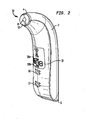
- Fig. 1 and 2 reveal a first embodiment of this invention.
- the laser device features a curvilinear housing 2 having a first end 4 and an opposite second end 6.
- An aperture defining a window 8 is formed at a tip 10 of the first end of the housing.
- the housing preferably has a sinusoidal or S-shape. This allows the tip 10 to be properly oriented against a user's face and simultaneously permits viewing by the user of power settings and activation.
- a longitudinal axis along a length of the housing and an axis traversing through the window at a point of intersection will define an angle between 100° and 170°, preferably between 110° and 160°, and optimally between 120° and 140°.
- the capacitance sensor 50 as best shown in Fig. 3 and 4 is the form of an annular plate 12 and arranged at the first end of the housing.
- the annular plate surrounds window 8.
- the plate is opaque to electromagnetic radiation. Any output beam of electromagnetic radiation is emitted through the window 8 which is an open central area of the annular plate.
- a bend relief joint 51 at a right angle connects the plate to an elongate arm 49 that electrically communicates with a printed circuitboard 28.
- the annular plate has at least three segments 54a, 54b, 54c each flexibly and independently movable in and out of a common plane. Each of the segments is connected to an electrode 52a, 52b, 52c. Dummy contact wires 53 serve as reference. Between each of the segments is a gap 56a, 56b, 56c of 1 to 20 mil.
- the electrodes By arranging the electrodes in a ring, they stay concentric to the cross section of the window 8 through which the electromagnetic radiation is emitted.
- the arrangement maximizes the surface area of the sensor and allows maintenance of the smallest possible volume around the window 8.
- the capacitive sensor includes two conductors with a capacitance field between them. There are three capacitive switches related to each of the three electrodes. Each of the switches must satisfy a condition that it has the capacitance correlated with proper dry skin contact. When there is only partial contact with the skin, the dielectric is improper and firing of the laser member cannot occur.
- buttons are activatable from outside the housing.
- One is a power activating button 14 functioning to arm/power on the device.
- the other is a power setting button 16 functioning to control the power level.
- the term "button" is to be interpreted broadly. Although in the first embodiment, the buttons are square, these may in other embodiments be of a round or other geometrical shape. Also these buttons may be movable inward/outward from a surface of the housing, but in another embodiment may be a non-movable touch screen form of switch.
- LED light emitting diode
- Fig. 5 and 6 reveal the inner mechanism of the laser device.
- a rechargeable battery 20 is lodged within a lower area of the housing just above the rear end 6. Recharging is achieved by connection of an outside power source to port 22 electrically communicating with the rechargeable battery.
- the battery is an aluminum block 24 serving both as a support and solid coolant to dissipate heat generated by the laser member.
- the device neither needs nor features any special liquid or gas coolant system.
- a laser member 26 generating electromagnetic radiation is supported on an arm of the aluminum block.
- the laser member of this embodiment operates on a constant output power delivering a continuous wave over time. It is a solid state diode laser including the elements indium, arsenic, gallium and tin.
- the laser produces a pulse of radiation having a wavelength between approximately 1300 and 1600 nm, preferably between 1420 and 1470 nm, and optimally about 1440 nm. Fluence may range between 0.5 and 5 joules/cm 2 , more preferably between 1 and 3 joules/cm 2 , and optimally between 1.3 and 1.8 joules/cm 2 .
- Electromagnetic radiation emanating from the laser device is non-ablative to the skin being classified by the U.S. Food & Drug Administration as a Class I/1 inherently safe rating.
- a signal and control storage device Upstream from the laser member 26 is a signal and control storage device in a form of a printed circuitboard 28 supported on the arm of the aluminum block 24. Operation of the device is controlled by the printed circuitboard including power switching, radiation fire sequencing, generation, timing, sequencing of laser pulses and processing of skin contact information.
- the signal and control storage device communicates with the sensor comparing input signals of measured dielectric constant values to a stored standard dielectric constant value of skin. Emission of the output beam is activated to fire only when all of the at least three segments align in a plane and sense the stored standard dielectric constant value.
- the submount Between the laser member 26 and the aluminum block 24 is a submount 34 as best seen in Fig. 5 .
- the submount directly supports the laser member and also a flexible electrically conductive connector 36 carrying signals/current from the printed circuitboard 28.
- the flexible electrically conductive connector features forward and rear ends 38, 42.
- An area 39 between the forward and rear ends is highly bendable. The bending may range from 0 to 360° in angle. This allows various angles between a major plane of the laser member and a major plane of the printed circuitboard. Preferably, the angle is held between 10 and 250°. This flexibility in orientation creates a geometric and ergonomic advantage.
- the forward end of the flexible connector is bonded to the submount. A portion of the forward end features a set of several wire bonds 40 which complete the electrical connection to the laser member 26.
- the rear end 42 of the flexible connector features an aperture 44 for a screw 46 or other fastening member to achieve a press contact with the printed circuitboard.
- the screw and a washer assembly provides an evenly distributed force which compresses a large area of the flexible connector to a plated contact on the printed circuit board. This arrangement minimizes contact resistance, thus lowering electrical power loss. This arrangement also allows for ease of assembly, disassembly and replacement.
- Flexible connectors in one embodiment of this invention are formed of a set of copper wires sandwiched between layers of polyimide.
- an alignment structure 48 Fashioned in a downstream area of the submount 34 is an alignment structure 48 with outwardly tapering walls.
- the alignment structure receives the forward end 38 of the flexible connector to prevent movement and insuring the laser member is properly oriented.
Landscapes
- Health & Medical Sciences (AREA)
- Life Sciences & Earth Sciences (AREA)
- Engineering & Computer Science (AREA)
- Biomedical Technology (AREA)
- Physics & Mathematics (AREA)
- Nuclear Medicine, Radiotherapy & Molecular Imaging (AREA)
- Animal Behavior & Ethology (AREA)
- General Health & Medical Sciences (AREA)
- Public Health (AREA)
- Veterinary Medicine (AREA)
- Optics & Photonics (AREA)
- Surgery (AREA)
- Pathology (AREA)
- Radiology & Medical Imaging (AREA)
- Biophysics (AREA)
- Electromagnetism (AREA)
- Otolaryngology (AREA)
- Heart & Thoracic Surgery (AREA)
- Medical Informatics (AREA)
- Molecular Biology (AREA)
- Radiation-Therapy Devices (AREA)
- Laser Surgery Devices (AREA)
Description
- The invention concerns a cordless handholdable laser device featuring a sensor controlling beam activation to insure an eye safe operation.
- Devices based on light amplification by stimulated emission of radiation (laser) have revolutionized many areas of dermatological medicine and of cosmetics. Amongst skin conditions responsive to treatment are acne scars, rosacea, hyperpigmentation, unwanted hair and dermal rejuvenation. Ablative resurfacing has become a common method for cosmetic rejuvenation. Wrinkle reduction has been a particular objective of the phototherapy.
- Advances in laser based devices and their use in skin treatment methods have been many during the last decade. Several publications have focused on safe arming of the device to avoid unintended exposures.
US 2004/0167502 A1 (Weckwerth et al. ) reports optical sensors for detecting engagement with a skin surface. The sensors are based upon multiple light emitting diodes, each having a unique wavelength band, and a broad-band photodetector to measure the remission of light at multiple wavelengths from a material being analyzed.US 2010/0082020 (Gong et al. ) describes a medical laser having a capacitance sensor and an emission control device to ensure that a laser handpiece is in contact with skin prior to activation. The handpiece needs to stand perpendicular to the skin surface before any surgical operation begins. - Most electromagnetic radiation delivery devices for treatment of skin are relatively large pieces of equipment. Complexity in their basic engineering and mode of operation defeats miniaturization into a handheld device. For instance,
US 2008/0082089 A1 (Jones et al. ) describes a system including a first solid-state and a second solid-state laser. A respective first output beam is fed into the second device for generating excitation in a rare earth doped gain medium to produce a second output beam. The latter is used to treat skin.US 2007/0179481 A1 (Frangineas et al. ) seeks to treat skin laxity with a plurality of pulses from a carbon dioxide laser. The system requires a housing to contain a scanning apparatus and a tip connected to a vacuum pump for exhausting smoke resulting from ablation. - Many of the reported ablative procedures require special cooling mechanisms. For instance,
US 5 810 801 directs a beam of radiation to penetrate the dermal region below a wrinkle to injure collagen. A cooling system is then activated to prevent injury of the overlying epidermis. These cooling systems are often quite bulky. - Another problem with the state of the art, particularly with portable instruments, is in their effectiveness to emit sufficiently energetic doses of electromagnetic radiation.
US 2011/0040358 A1 (Bean et al. ) provides one solution describing a portable device which is eye safe operating between 1350-1600 nm to treat wounds and diseases. This is a battery operated system that need not directly contact tissue. A key part of the device is a lens constructed to have the laser beam converge to a focal point slightly above the tissue surface target. - A laser device for treating skin is provided which includes:
- (i) a handholdable housing with a first end and a second end;
- (ii) a laser member arranged within the housing and emitting an output beam;
- (iii) a capacitance sensor arranged at the first end of the housing including a plate surrounding and defining a window through which the output beam exits, the plate having at least three segments each flexibly movable in and out of a common plane, each of the segments being connected to an electrode, the electrodes operating to determine dielectric constant of a skin surface; and
- (iv) a signal and control storage device communicating with the sensor comparing input signals of measured dielectric constant values to a stored standard dielectric constant value;
- Further features, aspects and benefits of the present invention will become more readily apparent from consideration of the following drawing in which:
-
Fig. 1 is a front view of one embodiment of the invention; -
Fig. 2 is a plan perspective view of the embodiment according toFig. 1 ; -
Fig. 3 is a front view focused on the sensor and connecting electrodes; -
Fig. 4 is a rear view of the sensor with electrodes shown inFig. 3 ; -
Fig. 5 is a cross-sectional view ofFig. 1 taken perpendicular to that view; -
Fig. 6 is a view of the internal mechanism separated from the housing ofFig. 1 ; and -
Fig. 7 is a semi-schematic view of a portion ofFig. 6 encompassing the laser member and the signal and control storage device. - Now we have developed a laser device in a highly compact handholdable configuration for treating skin. In a preferred format, the device is cordless and meets power needs through a rechargeable battery.
- Safety, especially with respect to eye damage, has been addressed by a special capacitance sensor. The sensor in a preferred embodiment is an annular ring of three sections, each connected to a different electrode. The laser member will not fire until all segments of the annular ring are firmly placed against the skin and are all registering a dielectric constant appropriate to a skin surface.
-
Fig. 1 and2 reveal a first embodiment of this invention. The laser device features acurvilinear housing 2 having a first end 4 and an oppositesecond end 6. An aperture defining a window 8 is formed at atip 10 of the first end of the housing. - The housing preferably has a sinusoidal or S-shape. This allows the
tip 10 to be properly oriented against a user's face and simultaneously permits viewing by the user of power settings and activation. A longitudinal axis along a length of the housing and an axis traversing through the window at a point of intersection will define an angle between 100° and 170°, preferably between 110° and 160°, and optimally between 120° and 140°. - The
capacitance sensor 50 as best shown inFig. 3 and 4 is the form of anannular plate 12 and arranged at the first end of the housing. The annular plate surrounds window 8. The plate is opaque to electromagnetic radiation. Any output beam of electromagnetic radiation is emitted through the window 8 which is an open central area of the annular plate. Abend relief joint 51 at a right angle connects the plate to anelongate arm 49 that electrically communicates with a printedcircuitboard 28. - The annular plate has at least three
segments electrode Dummy contact wires 53 serve as reference. Between each of the segments is agap - By arranging the electrodes in a ring, they stay concentric to the cross section of the window 8 through which the electromagnetic radiation is emitted. The arrangement maximizes the surface area of the sensor and allows maintenance of the smallest possible volume around the window 8.
- The capacitive sensor includes two conductors with a capacitance field between them. There are three capacitive switches related to each of the three electrodes. Each of the switches must satisfy a condition that it has the capacitance correlated with proper dry skin contact. When there is only partial contact with the skin, the dielectric is improper and firing of the laser member cannot occur.
- Two control buttons are activatable from outside the housing. One is a
power activating button 14 functioning to arm/power on the device. The other is apower setting button 16 functioning to control the power level. The term "button" is to be interpreted broadly. Although in the first embodiment, the buttons are square, these may in other embodiments be of a round or other geometrical shape. Also these buttons may be movable inward/outward from a surface of the housing, but in another embodiment may be a non-movable touch screen form of switch. - In conjunction with the power setting button, there is a light emitting diode (LED) 18 for indicating the setting of high or
low power -
Fig. 5 and6 reveal the inner mechanism of the laser device. Arechargeable battery 20 is lodged within a lower area of the housing just above therear end 6. Recharging is achieved by connection of an outside power source to port 22 electrically communicating with the rechargeable battery. - Above the battery is an
aluminum block 24 serving both as a support and solid coolant to dissipate heat generated by the laser member. The device neither needs nor features any special liquid or gas coolant system. - A
laser member 26 generating electromagnetic radiation is supported on an arm of the aluminum block. The laser member of this embodiment operates on a constant output power delivering a continuous wave over time. It is a solid state diode laser including the elements indium, arsenic, gallium and tin. The laser produces a pulse of radiation having a wavelength between approximately 1300 and 1600 nm, preferably between 1420 and 1470 nm, and optimally about 1440 nm. Fluence may range between 0.5 and 5 joules/cm2, more preferably between 1 and 3 joules/cm2, and optimally between 1.3 and 1.8 joules/cm2. Electromagnetic radiation emanating from the laser device is non-ablative to the skin being classified by the U.S. Food & Drug Administration as a Class I/1 inherently safe rating. - Upstream from the
laser member 26 is a signal and control storage device in a form of a printedcircuitboard 28 supported on the arm of thealuminum block 24. Operation of the device is controlled by the printed circuitboard including power switching, radiation fire sequencing, generation, timing, sequencing of laser pulses and processing of skin contact information. With regard to the latter, the signal and control storage device communicates with the sensor comparing input signals of measured dielectric constant values to a stored standard dielectric constant value of skin. Emission of the output beam is activated to fire only when all of the at least three segments align in a plane and sense the stored standard dielectric constant value. - Between the
laser member 26 and thealuminum block 24 is a submount 34 as best seen inFig. 5 . The submount directly supports the laser member and also a flexible electricallyconductive connector 36 carrying signals/current from the printedcircuitboard 28. The flexible electrically conductive connector features forward andrear ends area 39 between the forward and rear ends is highly bendable. The bending may range from 0 to 360° in angle. This allows various angles between a major plane of the laser member and a major plane of the printed circuitboard. Preferably, the angle is held between 10 and 250°. This flexibility in orientation creates a geometric and ergonomic advantage. - The forward end of the flexible connector is bonded to the submount. A portion of the forward end features a set of
several wire bonds 40 which complete the electrical connection to thelaser member 26. Therear end 42 of the flexible connector features anaperture 44 for ascrew 46 or other fastening member to achieve a press contact with the printed circuitboard. The screw and a washer assembly provides an evenly distributed force which compresses a large area of the flexible connector to a plated contact on the printed circuit board. This arrangement minimizes contact resistance, thus lowering electrical power loss. This arrangement also allows for ease of assembly, disassembly and replacement. - The flexibility of the connector allows the system to escape the ordinarily required connection of circuitry to be in a plane of the output beam generated by the laser. Flexible connectors in one embodiment of this invention are formed of a set of copper wires sandwiched between layers of polyimide.
- Fashioned in a downstream area of the
submount 34 is analignment structure 48 with outwardly tapering walls. The alignment structure receives theforward end 38 of the flexible connector to prevent movement and insuring the laser member is properly oriented. - In summary, the present invention is described above in terms of a preferred and other embodiments. The invention is not limited, however, to the described and depicted embodiments. Rather, the invention is only limited by the claims appended hereto.
Claims (5)
- A laser device for treating skin comprising:(i) a handholdable housing (2) with a first end (4) and a second end (6);(ii) a laser member arranged within the housing and emitting an output beam;(iii) a capacitance sensor (50) arranged at the first end of the housing comprising a plate (12) surrounding and defining a window (8) through which the output beam exits, the plate having at least three segments (54a, 54b, 54c) each flexibly movable in and out of a common plane, each of the segments being connected to an electrode (52a, 52b, 52c), the electrodes operating to determine dielectric constant of a skin surface; and(iv) a signal and control storage device (28) communicating with the sensor comparing input signals of measured dielectric constant values to a stored standard dielectric constant value;
wherein emission of the output beam is activated to fire only when all of the at least three segments align in a plane and sense the stored standard dielectric constant value;
and wherein the plate is an annular ring with the segments being three in number and each segment occupies one third of the annular ring, a non-electrical conductive gap (56a, 56b, 56c) separating each of the segments. - A device according to claim 1 wherein the signal and control storage device is a printed circuitboard (28).
- A device according to any one of the preceding claims wherein the output beam emits electromagnetic radiation of wavelength ranging from 1420 to 1470 nm.
- A device according to any one of the preceding claims wherein the output beam has a fluence range from 0.5 to 5 joules/cm2.
- A device according to claim 3 wherein the output beam has a fluence range from 1 to 3 joules/cm2.
Applications Claiming Priority (2)
| Application Number | Priority Date | Filing Date | Title |
|---|---|---|---|
| US201161512433P | 2011-07-28 | 2011-07-28 | |
| PCT/EP2012/063921 WO2013014017A1 (en) | 2011-07-28 | 2012-07-16 | Handholdable laser device featuring sensor for eye safe activation |
Publications (2)
| Publication Number | Publication Date |
|---|---|
| EP2736438A1 EP2736438A1 (en) | 2014-06-04 |
| EP2736438B1 true EP2736438B1 (en) | 2015-09-09 |
Family
ID=46514372
Family Applications (1)
| Application Number | Title | Priority Date | Filing Date |
|---|---|---|---|
| EP12735542.8A Not-in-force EP2736438B1 (en) | 2011-07-28 | 2012-07-16 | Handholdable laser device featuring sensor for eye safe activation |
Country Status (7)
| Country | Link |
|---|---|
| US (1) | US8968281B2 (en) |
| EP (1) | EP2736438B1 (en) |
| JP (1) | JP2014526922A (en) |
| CN (1) | CN103781435B (en) |
| BR (1) | BR112014002077A2 (en) |
| IL (1) | IL230554A0 (en) |
| WO (1) | WO2013014017A1 (en) |
Families Citing this family (8)
| Publication number | Priority date | Publication date | Assignee | Title |
|---|---|---|---|---|
| KR101508555B1 (en) | 2014-11-18 | 2015-04-07 | (주)휴레이저 | Handpiece treatment apparatus with cutter |
| KR101508557B1 (en) | 2014-11-24 | 2015-04-07 | (주)휴레이저 | Handpiece treatment apparatus using laser |
| CN106621053A (en) * | 2015-11-02 | 2017-05-10 | 艾科产品有限公司 | Beauty device with safety structure |
| CN107080892A (en) * | 2016-02-15 | 2017-08-22 | 北京拓殖智业科技有限公司 | A kind of optoelectronic integration therapeutic system with function of safety protection |
| USD827842S1 (en) * | 2017-01-10 | 2018-09-04 | Reckitt Benckiser (Brands) Limited | Skin treatment device with roller head |
| USD827843S1 (en) * | 2017-01-10 | 2018-09-04 | Reckitt Benckiser (Brands) Limited | Skin treatment device |
| USD862717S1 (en) * | 2018-05-08 | 2019-10-08 | Davinci Ii Csj, Llc | Skin treatment apparatus |
| WO2024089699A1 (en) * | 2022-10-27 | 2024-05-02 | Collplant Ltd. | Formulations for use in additive manufacturing, containing a tetracycline compound as a light-absorbing substance |
Family Cites Families (23)
| Publication number | Priority date | Publication date | Assignee | Title |
|---|---|---|---|---|
| US20080294152A1 (en) | 1996-12-02 | 2008-11-27 | Palomar Medical Technologies, Inc. | Cooling System For A Photocosmetic Device |
| US5810801A (en) | 1997-02-05 | 1998-09-22 | Candela Corporation | Method and apparatus for treating wrinkles in skin using radiation |
| CN2318987Y (en) * | 1998-04-10 | 1999-05-19 | 深圳奥沃国际科技发展有限公司 | Safety laser face beautifying device |
| WO2002065904A1 (en) * | 2001-02-23 | 2002-08-29 | Cordless Antistatic Research Inc. | Enhanced pickup bio-electrode |
| US20070038206A1 (en) | 2004-12-09 | 2007-02-15 | Palomar Medical Technologies, Inc. | Photocosmetic device |
| US8709003B2 (en) * | 2003-02-25 | 2014-04-29 | Tria Beauty, Inc. | Capacitive sensing method and device for detecting skin |
| US20100069898A1 (en) | 2003-02-25 | 2010-03-18 | Tria Beauty, Inc. | Acne Treatment Method, System and Device |
| US7413567B2 (en) | 2003-02-25 | 2008-08-19 | Spectragenics, Inc. | Optical sensor and method for identifying the presence of skin |
| US7892525B2 (en) | 2003-08-22 | 2011-02-22 | Lubrizol Advanced Materials, Inc. | Antiperspirant gel compositions |
| WO2005065565A1 (en) * | 2003-12-31 | 2005-07-21 | Palomar Medical Technologies, Inc. | Dermatological treatment with vusualization |
| US7856985B2 (en) | 2005-04-22 | 2010-12-28 | Cynosure, Inc. | Method of treatment body tissue using a non-uniform laser beam |
| CN101351162A (en) * | 2005-10-19 | 2009-01-21 | 塞梅格公司 | Therapeutic device and method for delivering energy at multiple selectable depths in tissue |
| CA2535276A1 (en) | 2006-02-06 | 2007-08-06 | John Kennedy | Therapy device and system and method for reducing harmful exposure to electromagnetic radiation |
| WO2007095183A2 (en) | 2006-02-13 | 2007-08-23 | Reliant Technologies, Inc. | Laser system for treatment of skin laxity |
| EP2032064A2 (en) | 2006-06-27 | 2009-03-11 | Palomar Medical Technologies, Inc. | Handheld photocosmetic device |
| US20080082089A1 (en) | 2006-09-29 | 2008-04-03 | Candela Corporation | Treatment of Skin by a Solid-State Laser |
| US20080140164A1 (en) | 2006-12-06 | 2008-06-12 | Clrs Technology Corporation | Light emitting therapeutic devices and methods |
| KR100751227B1 (en) * | 2006-12-27 | 2007-08-23 | 주식회사 루트로닉 | Medical laser device with capacitive sensor and laser oscillation control |
| US8323253B2 (en) | 2007-02-23 | 2012-12-04 | Reliant Technologies, Inc. | Method and device for tightening tissue using electromagnetic radiation |
| JP4816571B2 (en) | 2007-05-28 | 2011-11-16 | パナソニック電工株式会社 | Optical hair removal equipment |
| US20110040358A1 (en) | 2008-03-03 | 2011-02-17 | Seminex Corporation | Portable Semiconductor Diode Laser for Medical Treatment |
| US8518027B2 (en) * | 2009-10-28 | 2013-08-27 | Tria Beauty, Inc. | Phototherapy device thermal control apparatus and method |
| DE102009057933B3 (en) * | 2009-12-11 | 2011-02-24 | Ident Technology Ag | Sensor device for detecting approach and touch of e.g. hand held device by hand, has electrode structure including transmission, compensation and receiving electrodes, where electrical field is received in receiving electrode |
-
2012
- 2012-03-07 US US13/413,747 patent/US8968281B2/en not_active Expired - Fee Related
- 2012-07-16 JP JP2014522029A patent/JP2014526922A/en active Pending
- 2012-07-16 BR BR112014002077A patent/BR112014002077A2/en not_active IP Right Cessation
- 2012-07-16 CN CN201280037808.6A patent/CN103781435B/en not_active Expired - Fee Related
- 2012-07-16 EP EP12735542.8A patent/EP2736438B1/en not_active Not-in-force
- 2012-07-16 WO PCT/EP2012/063921 patent/WO2013014017A1/en not_active Ceased
-
2014
- 2014-01-20 IL IL230554A patent/IL230554A0/en unknown
Also Published As
| Publication number | Publication date |
|---|---|
| WO2013014017A1 (en) | 2013-01-31 |
| US20130030422A1 (en) | 2013-01-31 |
| CN103781435B (en) | 2016-03-16 |
| BR112014002077A2 (en) | 2017-02-21 |
| IL230554A0 (en) | 2014-03-31 |
| CN103781435A (en) | 2014-05-07 |
| US8968281B2 (en) | 2015-03-03 |
| EP2736438A1 (en) | 2014-06-04 |
| JP2014526922A (en) | 2014-10-09 |
Similar Documents
| Publication | Publication Date | Title |
|---|---|---|
| EP2736595B1 (en) | Handholdable laser device featuring pulsing of a continuous wave laser | |
| US8968281B2 (en) | Handholdable laser device featuring sensor for eye safe activation | |
| US9005262B2 (en) | Radiation-based dermatological devices and methods | |
| US9220915B2 (en) | Devices and methods for radiation-based dermatological treatments | |
| US8685008B2 (en) | Devices and methods for radiation-based dermatological treatments | |
| US20120283709A1 (en) | Devices and Methods for Radiation-Based Dermatological Treatments | |
| EP2736593B1 (en) | Handholdable laser device featuring flexible connection between a laser and a printed circuit board | |
| US20130030423A1 (en) | Devices and Methods for Radiation-Based Dermatological Treatments | |
| CA2535276A1 (en) | Therapy device and system and method for reducing harmful exposure to electromagnetic radiation | |
| US20170035506A1 (en) | Laser Diode Package Arrangement with Interchangable Tip |
Legal Events
| Date | Code | Title | Description |
|---|---|---|---|
| PUAI | Public reference made under article 153(3) epc to a published international application that has entered the european phase |
Free format text: ORIGINAL CODE: 0009012 |
|
| 17P | Request for examination filed |
Effective date: 20140228 |
|
| AK | Designated contracting states |
Kind code of ref document: A1 Designated state(s): AL AT BE BG CH CY CZ DE DK EE ES FI FR GB GR HR HU IE IS IT LI LT LU LV MC MK MT NL NO PL PT RO RS SE SI SK SM TR |
|
| DAX | Request for extension of the european patent (deleted) | ||
| GRAP | Despatch of communication of intention to grant a patent |
Free format text: ORIGINAL CODE: EPIDOSNIGR1 |
|
| INTG | Intention to grant announced |
Effective date: 20150309 |
|
| GRAS | Grant fee paid |
Free format text: ORIGINAL CODE: EPIDOSNIGR3 |
|
| GRAA | (expected) grant |
Free format text: ORIGINAL CODE: 0009210 |
|
| AK | Designated contracting states |
Kind code of ref document: B1 Designated state(s): AL AT BE BG CH CY CZ DE DK EE ES FI FR GB GR HR HU IE IS IT LI LT LU LV MC MK MT NL NO PL PT RO RS SE SI SK SM TR |
|
| REG | Reference to a national code |
Ref country code: GB Ref legal event code: FG4D |
|
| REG | Reference to a national code |
Ref country code: AT Ref legal event code: REF Ref document number: 747474 Country of ref document: AT Kind code of ref document: T Effective date: 20150915 Ref country code: CH Ref legal event code: EP |
|
| REG | Reference to a national code |
Ref country code: IE Ref legal event code: FG4D |
|
| REG | Reference to a national code |
Ref country code: DE Ref legal event code: R096 Ref document number: 602012010402 Country of ref document: DE |
|
| REG | Reference to a national code |
Ref country code: NL Ref legal event code: MP Effective date: 20150909 |
|
| PG25 | Lapsed in a contracting state [announced via postgrant information from national office to epo] |
Ref country code: NO Free format text: LAPSE BECAUSE OF FAILURE TO SUBMIT A TRANSLATION OF THE DESCRIPTION OR TO PAY THE FEE WITHIN THE PRESCRIBED TIME-LIMIT Effective date: 20151209 Ref country code: LT Free format text: LAPSE BECAUSE OF FAILURE TO SUBMIT A TRANSLATION OF THE DESCRIPTION OR TO PAY THE FEE WITHIN THE PRESCRIBED TIME-LIMIT Effective date: 20150909 Ref country code: FI Free format text: LAPSE BECAUSE OF FAILURE TO SUBMIT A TRANSLATION OF THE DESCRIPTION OR TO PAY THE FEE WITHIN THE PRESCRIBED TIME-LIMIT Effective date: 20150909 Ref country code: GR Free format text: LAPSE BECAUSE OF FAILURE TO SUBMIT A TRANSLATION OF THE DESCRIPTION OR TO PAY THE FEE WITHIN THE PRESCRIBED TIME-LIMIT Effective date: 20151210 Ref country code: LV Free format text: LAPSE BECAUSE OF FAILURE TO SUBMIT A TRANSLATION OF THE DESCRIPTION OR TO PAY THE FEE WITHIN THE PRESCRIBED TIME-LIMIT Effective date: 20150909 |
|
| REG | Reference to a national code |
Ref country code: LT Ref legal event code: MG4D |
|
| REG | Reference to a national code |
Ref country code: AT Ref legal event code: MK05 Ref document number: 747474 Country of ref document: AT Kind code of ref document: T Effective date: 20150909 |
|
| PG25 | Lapsed in a contracting state [announced via postgrant information from national office to epo] |
Ref country code: RS Free format text: LAPSE BECAUSE OF FAILURE TO SUBMIT A TRANSLATION OF THE DESCRIPTION OR TO PAY THE FEE WITHIN THE PRESCRIBED TIME-LIMIT Effective date: 20150909 Ref country code: HR Free format text: LAPSE BECAUSE OF FAILURE TO SUBMIT A TRANSLATION OF THE DESCRIPTION OR TO PAY THE FEE WITHIN THE PRESCRIBED TIME-LIMIT Effective date: 20150909 Ref country code: SE Free format text: LAPSE BECAUSE OF FAILURE TO SUBMIT A TRANSLATION OF THE DESCRIPTION OR TO PAY THE FEE WITHIN THE PRESCRIBED TIME-LIMIT Effective date: 20150909 Ref country code: ES Free format text: LAPSE BECAUSE OF FAILURE TO SUBMIT A TRANSLATION OF THE DESCRIPTION OR TO PAY THE FEE WITHIN THE PRESCRIBED TIME-LIMIT Effective date: 20150909 |
|
| PG25 | Lapsed in a contracting state [announced via postgrant information from national office to epo] |
Ref country code: NL Free format text: LAPSE BECAUSE OF FAILURE TO SUBMIT A TRANSLATION OF THE DESCRIPTION OR TO PAY THE FEE WITHIN THE PRESCRIBED TIME-LIMIT Effective date: 20150909 |
|
| PG25 | Lapsed in a contracting state [announced via postgrant information from national office to epo] |
Ref country code: IS Free format text: LAPSE BECAUSE OF FAILURE TO SUBMIT A TRANSLATION OF THE DESCRIPTION OR TO PAY THE FEE WITHIN THE PRESCRIBED TIME-LIMIT Effective date: 20160109 Ref country code: IT Free format text: LAPSE BECAUSE OF FAILURE TO SUBMIT A TRANSLATION OF THE DESCRIPTION OR TO PAY THE FEE WITHIN THE PRESCRIBED TIME-LIMIT Effective date: 20150909 Ref country code: EE Free format text: LAPSE BECAUSE OF FAILURE TO SUBMIT A TRANSLATION OF THE DESCRIPTION OR TO PAY THE FEE WITHIN THE PRESCRIBED TIME-LIMIT Effective date: 20150909 Ref country code: CZ Free format text: LAPSE BECAUSE OF FAILURE TO SUBMIT A TRANSLATION OF THE DESCRIPTION OR TO PAY THE FEE WITHIN THE PRESCRIBED TIME-LIMIT Effective date: 20150909 Ref country code: SK Free format text: LAPSE BECAUSE OF FAILURE TO SUBMIT A TRANSLATION OF THE DESCRIPTION OR TO PAY THE FEE WITHIN THE PRESCRIBED TIME-LIMIT Effective date: 20150909 |
|
| PG25 | Lapsed in a contracting state [announced via postgrant information from national office to epo] |
Ref country code: PL Free format text: LAPSE BECAUSE OF FAILURE TO SUBMIT A TRANSLATION OF THE DESCRIPTION OR TO PAY THE FEE WITHIN THE PRESCRIBED TIME-LIMIT Effective date: 20150909 Ref country code: AT Free format text: LAPSE BECAUSE OF FAILURE TO SUBMIT A TRANSLATION OF THE DESCRIPTION OR TO PAY THE FEE WITHIN THE PRESCRIBED TIME-LIMIT Effective date: 20150909 Ref country code: RO Free format text: LAPSE BECAUSE OF FAILURE TO SUBMIT A TRANSLATION OF THE DESCRIPTION OR TO PAY THE FEE WITHIN THE PRESCRIBED TIME-LIMIT Effective date: 20150909 Ref country code: PT Free format text: LAPSE BECAUSE OF FAILURE TO SUBMIT A TRANSLATION OF THE DESCRIPTION OR TO PAY THE FEE WITHIN THE PRESCRIBED TIME-LIMIT Effective date: 20160111 |
|
| REG | Reference to a national code |
Ref country code: DE Ref legal event code: R097 Ref document number: 602012010402 Country of ref document: DE |
|
| PLBE | No opposition filed within time limit |
Free format text: ORIGINAL CODE: 0009261 |
|
| STAA | Information on the status of an ep patent application or granted ep patent |
Free format text: STATUS: NO OPPOSITION FILED WITHIN TIME LIMIT |
|
| 26N | No opposition filed |
Effective date: 20160610 |
|
| PG25 | Lapsed in a contracting state [announced via postgrant information from national office to epo] |
Ref country code: DK Free format text: LAPSE BECAUSE OF FAILURE TO SUBMIT A TRANSLATION OF THE DESCRIPTION OR TO PAY THE FEE WITHIN THE PRESCRIBED TIME-LIMIT Effective date: 20150909 Ref country code: SI Free format text: LAPSE BECAUSE OF FAILURE TO SUBMIT A TRANSLATION OF THE DESCRIPTION OR TO PAY THE FEE WITHIN THE PRESCRIBED TIME-LIMIT Effective date: 20150909 |
|
| PG25 | Lapsed in a contracting state [announced via postgrant information from national office to epo] |
Ref country code: BE Free format text: LAPSE BECAUSE OF FAILURE TO SUBMIT A TRANSLATION OF THE DESCRIPTION OR TO PAY THE FEE WITHIN THE PRESCRIBED TIME-LIMIT Effective date: 20150909 |
|
| REG | Reference to a national code |
Ref country code: DE Ref legal event code: R119 Ref document number: 602012010402 Country of ref document: DE |
|
| REG | Reference to a national code |
Ref country code: CH Ref legal event code: PL |
|
| GBPC | Gb: european patent ceased through non-payment of renewal fee |
Effective date: 20160716 |
|
| PG25 | Lapsed in a contracting state [announced via postgrant information from national office to epo] |
Ref country code: MC Free format text: LAPSE BECAUSE OF FAILURE TO SUBMIT A TRANSLATION OF THE DESCRIPTION OR TO PAY THE FEE WITHIN THE PRESCRIBED TIME-LIMIT Effective date: 20150909 |
|
| PG25 | Lapsed in a contracting state [announced via postgrant information from national office to epo] |
Ref country code: DE Free format text: LAPSE BECAUSE OF NON-PAYMENT OF DUE FEES Effective date: 20170201 Ref country code: FR Free format text: LAPSE BECAUSE OF NON-PAYMENT OF DUE FEES Effective date: 20160801 Ref country code: LI Free format text: LAPSE BECAUSE OF NON-PAYMENT OF DUE FEES Effective date: 20160731 Ref country code: CH Free format text: LAPSE BECAUSE OF NON-PAYMENT OF DUE FEES Effective date: 20160731 |
|
| REG | Reference to a national code |
Ref country code: FR Ref legal event code: ST Effective date: 20170331 |
|
| REG | Reference to a national code |
Ref country code: IE Ref legal event code: MM4A |
|
| PG25 | Lapsed in a contracting state [announced via postgrant information from national office to epo] |
Ref country code: GB Free format text: LAPSE BECAUSE OF NON-PAYMENT OF DUE FEES Effective date: 20160716 |
|
| PG25 | Lapsed in a contracting state [announced via postgrant information from national office to epo] |
Ref country code: IE Free format text: LAPSE BECAUSE OF NON-PAYMENT OF DUE FEES Effective date: 20160716 |
|
| PG25 | Lapsed in a contracting state [announced via postgrant information from national office to epo] |
Ref country code: LU Free format text: LAPSE BECAUSE OF NON-PAYMENT OF DUE FEES Effective date: 20160716 |
|
| PG25 | Lapsed in a contracting state [announced via postgrant information from national office to epo] |
Ref country code: SM Free format text: LAPSE BECAUSE OF FAILURE TO SUBMIT A TRANSLATION OF THE DESCRIPTION OR TO PAY THE FEE WITHIN THE PRESCRIBED TIME-LIMIT Effective date: 20150909 Ref country code: HU Free format text: LAPSE BECAUSE OF FAILURE TO SUBMIT A TRANSLATION OF THE DESCRIPTION OR TO PAY THE FEE WITHIN THE PRESCRIBED TIME-LIMIT; INVALID AB INITIO Effective date: 20120716 Ref country code: CY Free format text: LAPSE BECAUSE OF FAILURE TO SUBMIT A TRANSLATION OF THE DESCRIPTION OR TO PAY THE FEE WITHIN THE PRESCRIBED TIME-LIMIT Effective date: 20150909 |
|
| PG25 | Lapsed in a contracting state [announced via postgrant information from national office to epo] |
Ref country code: MT Free format text: LAPSE BECAUSE OF NON-PAYMENT OF DUE FEES Effective date: 20160731 Ref country code: MK Free format text: LAPSE BECAUSE OF FAILURE TO SUBMIT A TRANSLATION OF THE DESCRIPTION OR TO PAY THE FEE WITHIN THE PRESCRIBED TIME-LIMIT Effective date: 20150909 |
|
| PG25 | Lapsed in a contracting state [announced via postgrant information from national office to epo] |
Ref country code: BG Free format text: LAPSE BECAUSE OF FAILURE TO SUBMIT A TRANSLATION OF THE DESCRIPTION OR TO PAY THE FEE WITHIN THE PRESCRIBED TIME-LIMIT Effective date: 20150909 |
|
| PG25 | Lapsed in a contracting state [announced via postgrant information from national office to epo] |
Ref country code: AL Free format text: LAPSE BECAUSE OF FAILURE TO SUBMIT A TRANSLATION OF THE DESCRIPTION OR TO PAY THE FEE WITHIN THE PRESCRIBED TIME-LIMIT Effective date: 20150909 Ref country code: TR Free format text: LAPSE BECAUSE OF FAILURE TO SUBMIT A TRANSLATION OF THE DESCRIPTION OR TO PAY THE FEE WITHIN THE PRESCRIBED TIME-LIMIT Effective date: 20150909 |