EP2736228A1 - Handheld device with surface reflection estimation - Google Patents
Handheld device with surface reflection estimation Download PDFInfo
- Publication number
- EP2736228A1 EP2736228A1 EP12194101.7A EP12194101A EP2736228A1 EP 2736228 A1 EP2736228 A1 EP 2736228A1 EP 12194101 A EP12194101 A EP 12194101A EP 2736228 A1 EP2736228 A1 EP 2736228A1
- Authority
- EP
- European Patent Office
- Prior art keywords
- information
- message
- displayed
- light
- display screen
- Prior art date
- Legal status (The legal status is an assumption and is not a legal conclusion. Google has not performed a legal analysis and makes no representation as to the accuracy of the status listed.)
- Granted
Links
Images







Classifications
-
- H—ELECTRICITY
- H04—ELECTRIC COMMUNICATION TECHNIQUE
- H04M—TELEPHONIC COMMUNICATION
- H04M1/00—Substation equipment, e.g. for use by subscribers
- H04M1/02—Constructional features of telephone sets
- H04M1/22—Illumination; Arrangements for improving the visibility of characters on dials
-
- H—ELECTRICITY
- H04—ELECTRIC COMMUNICATION TECHNIQUE
- H04M—TELEPHONIC COMMUNICATION
- H04M2250/00—Details of telephonic subscriber devices
- H04M2250/12—Details of telephonic subscriber devices including a sensor for measuring a physical value, e.g. temperature or motion
-
- H—ELECTRICITY
- H04—ELECTRIC COMMUNICATION TECHNIQUE
- H04M—TELEPHONIC COMMUNICATION
- H04M2250/00—Details of telephonic subscriber devices
- H04M2250/52—Details of telephonic subscriber devices including functional features of a camera
Definitions
- the present disclosure relates generally to a method and handheld electronic device which estimates the reflectance of a surface that the device is facing.
- Handheld electronic devices such as mobile communication devices, can provide a number of features and applications including, for example, a phone application, media player application, mapping application, calendar application, email application, instant messaging (IM) application, text messaging application (e.g., for sending and receiving short message service (SMS) messages), and other applications.
- IM instant messaging
- SMS short message service
- a number of these applications generate notification messages for a device user. In some situations, it may be desirable to reflect information from the device off of a reflective surface.
- a method of estimating reflectance of a surface adjacent a handheld electronic device having a orientation sensor and a light sensor including estimating a location of the handheld electronic device relative to the surface in dependence on information from the orientation sensor; measuring reflected light from the surface with the light sensor; and estimating a reflectance of the surface in dependence on the estimated location and measured light.
- a handheld electronic device of performing the method is also described.
- FIG. 1 is a block diagram illustrating a handheld electronics device in the form of a mobile communication device in accordance with one example embodiment of the present disclosure
- FIG. 2 is a front view of the mobile communications device of FIG. 1 in a portrait orientation
- FIG. 3 is a front view of the mobile communication device in a landscape orientation
- FIG. 4 is a perspective view of the mobile communication device resting face down on a support surface
- FIG. 5 is a side view of the mobile communication device resting on the surface
- FIG. 6 is a side view of the mobile communication device tilted a first angle with respect to the surface
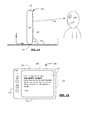
- FIG. 7 is a front view of the mobile communication device showing an image presented on the device when it is in the orientation of FIG. 6 ;
- FIG. 8 is a plan view of a reflective surface reflecting the image displayed on the mobile communication device of FIG. 7 ;
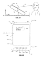
- FIG. 9 is a side view of the mobile communication device tilted a second angle with respect to the surface
- FIG. 10 is a front view of the mobile communication device showing an image presented on the device when it is in the orientation of FIG. 9 ;
- FIG. 11 is a plan view of a reflective surface reflecting the image displayed on the mobile communication device of FIG. 10 ;
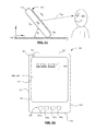
- FIG. 12 is a side view of the mobile communication device tilted a third angle with respect to the surface
- FIG. 13 is a front view of the mobile communication device showing an image presented on the device when it is in the orientation of FIG. 12 ;
- FIG. 14 is a side view of the mobile communication device tilted a fourth angle with respect to the surface
- FIG. 15 is a front view of the mobile communication device showing an image presented on the device when it is in the orientation of FIG. 14 ;
- FIG. 16 is a front view of the mobile communication device showing a sample surface selection interface
- FIG. 17 is an end view of the mobile communication device face up on a support surface
- FIG. 18 is a front view of the mobile communication device showing an image presented on the device when it is in the orientation of FIG. 17 ;
- FIG. 19 is an end view of the mobile communication device tilted a first angle with respect to the surface
- FIG. 20 is a front view of the mobile communication device showing an image presented on the device when it is in the orientation of FIG. 19 ;
- FIG. 21 is an end view of the mobile communication device tilted a second angle with respect to the surface
- FIG. 22 is a front view of the mobile communication device showing an image presented on the device when it is in the orientation of FIG. 21 ;
- FIG. 23 is an end view of the mobile communication device tilted a third angle with respect to the surface
- FIG. 24 is a front view of the mobile communication device showing an image presented on the device when it is in the orientation of FIG. 23 ;
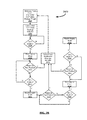
- FIG. 25 is a flow diagram representing a notification message display process corresponding to FIGS. 4-15 .
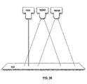
- FIG. 26 illustrates an IR emitter and sensors of an example embodiment of the device.
- Figures 27A to 27C are schematic diagrams illustrating the assignment of pitch and roll vectors of a three-axis accelerometer in accordance with one example embodiment of the present disclosure.
- Figure 28A is a front view of a portable electronic device showing sensing axes of three-axis accelerometer in accordance with one embodiment of the present disclosure.
- Figure 28B is a top view of the portable electronic device of Figure 28A .
- handheld electronic devices include mobile (wireless) communication devices such as pagers, cellular phones, Global Positioning System (GPS) navigation devices and other satellite navigation devices, smartphones, wireless organizers, personal digital assistants and wireless-enabled tablet computers.
- the handheld electronic device may be a portable electronic device without wireless communication capabilities such as a handheld electronic game device, digital photograph album, digital camera and video recorder such as a camcorder.
- the portable electronic devices could have a touchscreen display, a mechanical keyboard in addition to a touchscreen display, or a conventional non-touchscreen display with a mechanical keyboard. These examples are intended to be non-limiting.
- FIG. 1 illustrates a handheld electronics device in the form of a mobile communication device 201 to which example embodiments described in the present disclosure can be applied.
- the mobile communication device 201 is a two-way communication device having at least data and possibly also voice communication capabilities, and the capability to communicate with other computer systems, for example, via the Internet.
- the device may be a data communication device, a multiple-mode communication device configured for both data and voice communication, a smartphone, a mobile telephone, a tablet style-computer or a PDA (personal digital assistant) enabled for wireless communication, or a computer system with a wireless modem.
- PDA personal digital assistant
- the mobile communication device 201 includes a controller comprising at least one processor 240 such as a microprocessor which controls the overall operation of the mobile communication device 201, and a wireless communication subsystem 211 for exchanging radio frequency signals with the wireless network 101.
- the processor 240 interacts with the communication subsystem 211 which performs communication functions.
- the processor 240 interacts with additional device subsystems including a display screen 204, such as a liquid crystal display (LCD) screen, with a touch-sensitive input surface or overlay 206 connected to an electronic controller 208 that together make up a touchscreen display 210.
- the touch-sensitive overlay 206 and the electronic controller 208 provide a touch-sensitive input device and the processor 240 interacts with the touch-sensitive overlay 206 via the electronic controller 208.
- the device 201 could include other input devices such as a keyboard or keypad, navigational tool (input device), or both.
- the navigational tool could be a clickable/depressible trackball or scrollwheel.
- the other input devices could be included in addition to, or instead of, the touchscreen display 210.
- the processor 240 interacts with additional device subsystems including a camera sensor 232 (which may for example include a charge coupled device) and camera flash 230, flash memory 244, random access memory (RAM) 246, read only memory (ROM) 248, auxiliary input/output (I/O) subsystems 250, data port 252 such as serial data port, such as a Universal Serial Bus (USB) data port, speaker 256, microphone 258, control keys 260, light emitting diode (LED) 261, short-range communication subsystem 272, an orientation subsystem 249 and other device subsystems generally designated as 274.
- a camera sensor 232 which may for example include a charge coupled device
- flash memory 244 random access memory (RAM) 246, read only memory (ROM) 248, auxiliary input/output (I/O) subsystems 250
- data port 252 such as serial data port, such as a Universal Serial Bus (USB) data port
- speaker 256 such as a Universal Serial Bus (USB) data port
- microphone 258 control keys 260
- the mobile communication device 201 may communicate with any one of a plurality of fixed transceiver base stations of the wireless network 101 within its geographic coverage area.
- the mobile communication device 201 may send and receive communication signals over the wireless network 101 after a network registration or activation procedures have been completed.
- the processor 240 operates under stored program control and executes software modules 221 stored in memory such as persistent memory, for example, in the flash memory 244.
- the software modules 221 comprise operating system software 223 and software applications 225.
- a notification module 226 provides instructions for the processor 240 to operate the notification message privacy viewing functions described herein.
- Notification module 226 may, among other things, each be implemented through standalone software applications, or combined together in one or more of the operating system 223 or other software applications 225.
- the functions performed by the module 226 may be realized as a plurality of independent elements, rather than a single integrated element, and any one or more of these elements may be implemented as parts of other software applications 225 or operating system software 223.
- the software modules 221 or parts thereof may be temporarily loaded into volatile memory such as the RAM 246.
- the RAM 246 is used for storing runtime data variables and other types of data or information, as will be apparent to those skilled in the art. Although specific functions are described for various types of memory, this is merely one example, and those skilled in the art will appreciate that a different assignment of functions to types of memory could also be used.
- the software applications 225 may include a range of applications, including, for example, an address book application, a messaging application, a calendar application, and/or a notepad application.
- the software applications 225 include an email message application, one or more instant messaging applications, text messaging applications, a push content viewing application, a voice communication (i.e. telephony) application and a map application.
- Each of the software applications 225 may include layout information defining the placement of particular fields and graphic elements (e.g. text fields, input fields, icons, etc.) in the user interface (i.e. the display screen 204) according to the application.
- a predetermined set of applications that control basic device operations, including data and possibly voice communication applications will normally be installed on the mobile communication device 201 during or after manufacture. Additional applications and/or upgrades to the operating system 223 or software applications 225 may also be loaded onto the mobile communication device 201 through the wireless network 101, the auxiliary I/O subsystem 250, the serial port 252, the short-range communication subsystem 272, or other suitable subsystem 274 other wireless communication interfaces.
- the downloaded programs or code modules may be permanently installed, for example, written into the program memory (i.e. the flash memory 244), or written into and executed from the RAM 246 for execution by the processor 240 at runtime.
- the mobile communication device 201 may provide two principal modes of communication: a data communication mode and an optional voice communication mode.
- a received data signal such as a text message, an email message, or Web page download will be processed by the communication subsystem 211 and input to the processor 240 for further processing.
- a downloaded Web page may be further processed by a browser application or an email message may be processed by an email message application and output to the display 242.
- a user of the mobile communication device 201 may also compose data items, such as email messages, for example, using the touch-sensitive overlay 206 in conjunction with the display device 204 and possibly the control buttons 260 and/or the auxiliary I/O subsystems 250. These composed items may be transmitted through the communication subsystem 211 over the wireless network 101.
- the mobile communication device 201 provides telephony functions and operates as a typical cellular phone. The overall operation is similar, except that the received signals would be output to the speaker 256 and signals for transmission would be generated by a transducer such as the microphone 258.
- the telephony functions are provided by a combination of software/firmware (i.e., the voice communication module) and hardware (i.e., the microphone 258, the speaker 256 and input devices).
- Alternative voice or audio I/O subsystems such as a voice message recording subsystem, may also be implemented on the mobile communication device 201.
- voice or audio signal output is typically accomplished primarily through the speaker 256, the display device 204 may also be used to provide an indication of the identity of a calling party, duration of a voice call, or other voice call related information.
- the orientation subsystem 249 comprises at least one sensor which is coupled to the processor 240 and which is controlled by one or a combination of a monitoring circuit and operating software.
- the sensor has a sensing element which detects acceleration from motion and/or gravity.
- the sensor generates and outputs an electrical signal representative of the detected acceleration. Changes in movement of the portable electronic device 100 result in changes in acceleration which produce corresponding changes in the electrical signal output of the sensor.
- the sensor may be an accelerometer 251, such as a three-axis accelerometer having three mutual orthogonally sensing axes.
- the accelerometer 251 may be digital or analog depending on the embodiment.
- the accelerometer 251 may be utilized to detect acceleration of the portable electronic device 201, such as a direction of gravitational forces or gravity-induced reaction forces.
- Other types of motion sensors may be used by the orientation subsystem 223 in addition to, or instead of, an accelerometer.
- the other motion sensors may comprise a proximity sensor, gyroscope, or both, which detect changes in the proximity and orientation
- the device 201 includes a rigid case 304 for housing the components of the device 201 that is configured to be held or cradleable in a user's hand or hands while the device 201 is in use.
- the touchscreen display 210 is mounted within a front face 305 of the case 304 so that the case 304 frames the touchscreen display 210 with a generally planar display surface of the display screen 204 and the touchscreen overlay 206 facing forward for user-interaction therewith.
- the case 304 has top and bottom edges designated by references 322, 324 respectively, and left and right edges designated by references 326, 328 respectively which extend transverse to the top and bottom edges 322, 324.
- the case 304 (and device 201) is elongate having a length, defined between the top and bottom edges 322, 324, longer than a width, defined between the left and right edges 326, 328.
- Other device dimensions and form factors are also possible.
- hard control buttons or keys 260 are located on the case 304 of the device 201 to generate corresponding input signals when activated.
- some or all of keys 260 may be replaced soft keys implemented on display 210.
- the device 201 can be moved between portrait and landscape orientation modes, as seen in FIGS. 2 and 3 respectively.
- the device 201 may be configured, based on inputs from an orientation sensor 251 such as an accelerometer in orientation subsystem 249, to automatically detect its orientation and change the orientation of information displayed on display screen 206 between landscape and portrait in response thereto.
- the notification module 226 is configured to present notification messages on the display screen 206.
- the notification messages can be associated with various external trigger events - for example, the receipt of a new email message, text message, instant message, phone call or voice mail message at the device 201 can each result in an associated notification message that can be displayed on the display screen 204 to provide information about the newly received message or phone call.
- FIG. 2 illustrates an example of a notification message 370 generated by processor 240 in association with a new electronic message recently received at the device 201.
- FIG. 1 illustrates an example of a notification message 370 generated by processor 240 in association with a new electronic message recently received at the device 201.
- the notification message 370 includes a time field 372 indicating the time that the message was received at, a sender field 374 indicating a name or other identifier for the sending party, a message subject field 376 (in the case of an email message), and a content field 378.
- the content field 378 may include up to a predetermined number of characters from the original message content to allow a user to preview part of the message content.
- a user Upon viewing a notification message 370, a user has different options - for example, pressing a predetermined key such as key 260d may cause the entire message associated with the notification message 370 to be displayed; pressing a different predetermined key such as key 260c may cause a "compose reply" interface to be displayed to facilitate a reply to the message; and pressing yet a different predetermined key such as key 260b may cause the message notification 370 to be removed from the display screen 204.
- notification messages can also be associated with internal trigger events such as a task or calendar reminder, or movement of the device 201 into or out of a predefined geographic area, among other things, and in this regard FIG. 3 illustrates an example of a further notification message 370 generated by processor 240 in association with a calendar reminder for an upcoming calendar event stored in a calendar data associated with the device 201.
- the notification message 370 includes a time field 372 indicating the time of the calendar event, a meeting subject field 376, and a meeting location field 380.
- various types of services that push data or messages to the device 201 could act as trigger events that would cause the processor 240 to generate a corresponding notification message.
- messages from a social networking website such as messages regarding a change in status or posting of new information could act as trigger events, as could notification of new software updates available for download by the mobile device 20.
- the notification module 226 is configured to present information about notification messages 370 differently, depending on a sensed orientation of the electronic device 201, to enhance privacy of the user of the device.
- a tilt-activated notification message display process 2400 will now be explained with reference to the flow diagram of Figure 25 and Figures 4-15 .
- a new email message has arrived at device 201 resulting in information for a notification message 370 similar to that shown in Figure 2 .
- Figure 4 shows a perspective view of mobile device 201 in an initial, stationary, face down position resting on a generally planar horizontal support surface 402 with its generally planar display screen 204 facing downwards.
- support surface 402 represents the surface of a table or desk or podium for example.
- the X and Y axes extend in horizontal directions and the Z axis extends in a vertical direction.
- Figure 5 shows a side-view of the device 201 in the same facedown position as Figure 4.
- Figures 4 and 5 represent how a user may place his or her device 201 when sitting in a meeting or at a desk or standing near a flat support surface.
- the face down display screen 204 cannot be viewed, and accordingly any information on the display screen 204 is private.
- arrow "g" indicates the direction of gravitational force.
- the processor 240 is configured to monitor for a notification message trigger (for example a new message, or phone call, or a calendar or task reminder) and sense when the device 201 is in a stationary face down position as shown in Figure 4 and 5 .
- orientation sensing is based on inputs received from a position sensor such as an accelerometer 251 or gyroscope.
- other position sensing elements could be used to assist in determining device orientation, including for example inputs from camera sensor 232.
- the camera sensor 232 (or other light sensor) could be used to determine if the device is in a face down or face up position - for example, if a camera sensor 232 on the front face of the device detects very little ambient light, such information can be an indicator the device is face down on an opaque surface, and if a camera sensor 232 on the front face of the device detects a higher level of ambient light such information can be an indicator the device is face up.
- the device 201 may be configured to adjust a backlighting or display brightness of the display screen 204 in response to a level ambient lighting sensed by a sensor - such a feature can improve privacy as lower lighting levels can be used in darker environments to display notices on the display screen.
- the device 201 when the device 201 is in a face down stationary position for a predetermined length of time the device 201 enters a power saving mode in which the display screen 204 either goes blank or displays a default screen.
- the processor 240 causes a new notification message indicator to be generated - for example, a visual indication (indicated by lines 384 in Figure 4 ) can be provided to a user of the device by a flashing LED 261 located on a visible surface of the device such as the side edges or upward facing back 307.
- one or both of the flash rate or color of the LED 261 could be used to indicate the type of event for which the notification message is being generated, for example a new e-mail message, a new text message, a new instant message, a calendar reminder, a task reminder or a new voice mail message.
- the flash rate or color or both of the LED 261 could also be used to indicate the number of un-viewed or new notification messages waiting to be viewed.
- the device 201 may alternatively, or also, provide a physical indication in the form of a vibration or an aural indication in the form of a sound indicating that a new notification message is available to the user of the device 201.
- the flash 230 associated with device camera sensor 232 could be controlled to provide a new notification message indication.
- the display screen could be configured so that some light leaks even when the display screen is face down, and the display screen flashed repeatedly (for example, all red) for a predetermined duration to visually provide a new notification message indication.
- the new notification message indicator generated in Action 2404 can be perceived by various people in the proximity of the device 201, however the new notification message indicator provides little or no details about the content or character of the notification message.
- the device 201 can be configured to suppress the new notification message indicator so that information that a new notification message is waiting to be viewed can be hidden.
- the processor 240 monitors the face down device 201 to determine if the device 201 is tilted to a first orientation that exceeds a threshold angle "a" from its stationary, face down position.
- the processor 240 is effectively monitoring to see if a device user 604 tilts the device upwards on the support surface 402. More specifically, based on input from orientation subsystem 249, the processor 240 detects when the device 201 is tilted at least "a" degrees relative to a horizontal plane, that is, the angle between the display screen 204 and the horizontal surface in this example.
- the tilt axis is parallel to the horizontal plane that runs into the paper along the Y axis, and is generally parallel to the device side edge 328 and the planar display screen 204 - thus the processor 204 monitors to determine if the edge of the device 201 that is closest to a device user 604 (edge 326 in Figure 6 ) is being tilted up while the edge of the device furthest from the user (edge 328 in Figure 6 ) remains substantially resting on the support surface 402. Once the threshold tilt angle "a" is reached, the processor 240 causes selected information 702 from the notification message 370 to be displayed in a first notification message display mode on the display screen as shown in Figure 7 (Action 2408).
- the displayed information 702 is displayed so that it can be viewed as a reflection off of the support surface 402 - arrow 602 illustrates the path of light from the display screen 204, reflected of surface 402, as viewed by device user 604.
- Figure 8 is a plan view showing the reflected image 702R projected onto the surface 402 - dashed line 201' represents the footprint of the device 201 over the surface 402, which effectively blocks the reflected image 702R from potential viewers who are not positioned in the location of device user 602, thus preserving the privacy of the displayed information 702.
- the displayed information 702 is presented on the display screen 204 as an inverted mirror image a shown in Figure 7 .
- each character is inverted, i.e. rotated 180 degrees from how it would normally be presented, and the vertical ordering of the displayed lines of text reversed so that the lowest line becomes the top line.
- the displayed information 702 only includes selected fields from the notification message 370, notably the sender field, subject field and time field - the content field is omitted. In different embodiments, more or less information or fields from the notification message 370 could be included in the displayed information 702, and in some examples the amount of displayed information could be user configurable.
- the displayed information 702 is positioned on display screen 204 closer to the raised edge 326 than the pivot edge 328 of the device 201, in recognition of the fact that at lower pivot angles it will be easier for the device user 604 to see reflections located closer to the higher raised edge 326 of the device 201.
- the device user 604 can discretely view reflected image 702R with the reflection being substantially blocked from other peoples' view by the device 201.
- the processor 240 in addition to displaying information 702, the processor 240 also causes a region 704 (see Figure 7 ) of the display screen to be lit up as the device 201 is tilted, resulting in a reflected image 704R on surface 402(see Figure 8 ).
- the illuminated region 704 is either color coded or flash coded or both to provide some information about the notification message - for example flashing red to indicate a new email message, solid red for a text message, blue for calendar reminder, etc.
- the border region 704 is displayed as soon as the device 201 begins to get tilted and turns off once the angle "a" or some other threshold angle is reached.
- the displayed information may be scrolled across the display screen 204 to increase the amount of information presented, or the size of the characters adjusted for enhanced readability.
- the scrolling speed can be controlled by pivoting the device 201 back and forth within a range of the threshold angle for the current display mode. For example, tilting back down could slow the scroll speed and tilting back up could increase the scroll speed.
- the displayed information may scroll while the device is moved within a range of the threshold angle and stop scrolling when the device is held at stationary tilt angle, thus permitting the user to scroll the displayed information by tilting the device and freeze the displayed information by maintaining the device at a stable tilt angle.
- the processor 240 monitors to determine if the device 201 is tilted back down into is starting display screen face down position of Figure 5 , and if the device 201 is returned to its face-down position, the new notification message indicator 2412 is turned off and the displayed notification information removed from the display screen (action 2412).
- a new message marker is also displayed on a status bar portion of the device screen.
- Figure 2 shows a new message marker 380 in the form of a "spat" (shown as a star) over a mail indicator displayed in the status bar region of the display screen 204.
- the new message marker 380 remains active until the associated message is actually viewed, regardless of whether information from the notification message associated with the new message is viewed by tilting the device. For example - a quick tilt of the device 201 could be used to turn off the new notification message indicator 384 (with or without the message 702 actually getting viewed) but the new message marker 380 associated with the message could remain active.
- the displayed information 702 is modified and displayed in a second display mode (Actions 2414, 2416).
- the displayed information 702 in Figures 9-11 at tilt angle "b" is the same as displayed as it was at the smaller tilt angle "a", however the positioning of the displayed information 702 has shifted down to a position on the display screen 204 that is closer to the pivot edge 328 of the device 201 rather than the raised edge 326.
- Such a feature recognizes that the further the displayed information is from the surface 402 the weaker the reflected image 702A - hence shifting the displayed information 702 as the tilt angle increases keeps the image close to the surface 402, improving the reflected image 702R.
- the displayed information 702 could be shifted in one discrete step as the angle "b" was reached, or alternatively the displayed information 702 be incrementally stepped or continuously “slid” or scrolled down or up the screen as an animation between the positions shown in Figures 7 and 10 , as the user tilted the device further up or down, and the image could be maintained in a constant position when the device was maintained at a constant tilt angle.
- the displayed notification message information is modified again and displayed in a third display mode (Actions 2420 and 2422).
- FIGs 12 and 13 which show side and front views of the device 201 at tilt angle "c"
- selected notification message information 710 is displayed on the display screen 204 in a manner to facilitate direct viewing by the device user 604, as shown by light path 606, at a small direct viewing angle "v" relative to the display screen.
- the displayed notification message information 710 (which can be less, the same as, or more than the information included in displayed information 702) is displayed as having a distorted or perception corrected or perception modified font compared to the default display font used by the device 201.
- the displayed information 710 can be displayed with vertically stretched text having a text height H to text width W aspect ratio that is substantially larger than the default font.
- the aspect ratio may vary from the top of the text to the bottom, such that the text width W(B) at the bottom of the displayed text is wider than the text width W(T) at the top of the displayed text, providing a keystone effect that allows the text to be read at small viewing angle "v".
- the displayed information 710 can scroll across the display screen 204, and the rate of scrolling described in the manner described above by adjusting the tilt angle within a range about angle "c".
- the aspect ratio of the displayed information 710 is adaptively adjusted as the tilt angle changes within a range of angle "c" to accommodate different viewing angles "v”.
- the displayed notification message information is modified again and displayed in a forth display mode (Actions 2426 and 2428).
- angle "d" represents a standard direct viewing angle for the device 604, and all fields of the notification message 370 are displayed in default font size on the display screen 204.
- tilting to the fourth orientation causes the entire electronic message to be shown on the display screen within a message viewing user interface function of a messaging application on the device 301 and the message is then tracked by the device as being "read".
- the notification message viewing process described above allows a device user to discretely view notification messages and progress through a series of viewing modes that are dependent on the device tilt angle in order to control the manner and amount of information displayed by the device 201.
- the pivot edge is shown as right side edge 328 in Figures 6-15 , with the device 201 taking a landscape orientation.
- the processor 240 is configured to detect which of the four side edges 322, 324, 326 or 328 is used as the pivot edge and display the notification information accordingly.
- the processor 240 is configured to only accept one edge (for example bottom side edge 324), providing further possible privacy as the information will only be displayed when tilting occurs on the designated tilt edge.
- which edges can be designated as acceptable tilt edges is user configurable.
- the display modes are reversible such that tilting the device back down switches through the display modes in the reverse order.
- the device 201 is configured to accept other or alternative user inputs (in addition to device tilting) to advance through the various notification message display modes - for example, a verbal command, a touch screen tap, or user activation of one or more of the control keys 260 (one or more of which could be located on a side edge of the device such as volume keys) could be used to switch between the display modes such as those shown in Figures 8 , 11 , 13 and 15 .
- a motion or orientation sensor such as the accelerometer 251 of the device could be used to detect a "tap" by a user's finger on the back of the device 201, and the device 201 be configured to advance to a next display mode on detecting a tap input.
- the device 201 in addition to displaying a new message notification identifier 384 and a new message marker 380, the device 201 also marks messages as "read” and "unread” in a message list generated by a message viewing application resident on the device. For example an unread message may be identified by an open envelope icon or bold text or both.
- the new message notification identifier 384, new message marker 390 and "read"/"unread” marker can each be individually controlled based on the tilt angle of the device 201 and the duration the device remains at such tilt angles.
- tilting of the device 201 away from its stationary face down position for even a moment could cause the new message notification identifier 384 to disappear without affecting the message marker 390 and "read"/"unread” marker, and tilting of the device for a threshold period to a threshold orientation could cause the new message marker 390 to be removed without affecting the "read"/"unread” marker, and tilting yet further distance for a threshold period cause the "read" marker to be activated.
- the reflective viewing modes shown in Figures 6-11 could be used to discretely view information other than notification message information on the display screen- for example, tilting of the device in the could cause a clock image showing the current time to be projected onto the support surface so the reflected clock image can be viewed in correct orientation.
- the reflected clock image could be displayed when the device is tilted and there is no pending new message notification to display.
- angles "a”, “b” and “c” are 70 degrees or less, and angle “d” 90 degrees or less - by way of non limiting example, angle “a” could be between 1 and 5 degrees; angle “b” between 10 and 20 degrees greater than angle “a”; angle “c” between 10 and 30 degrees greater than angle “b”; and angle “d” between 20 and 40 degrees greater than angle “c”.
- the threshold angles have can be user configured to vary from preset default values.
- the starting position of the device may not be completely horizontal - for example the device 201 could be face down on an angled podium.
- the threshold angles could in some embodiments be determined relative to the starting position or relative to a absolute horizontal plane or a combination thereof.
- the resting position could be used as a base-line position from which angles a, b, c and d are calculated and measured.
- the amount of information displayed in each of the display modes can be dependent on whether or not the device is locked.
- the tilt display modes may be disabled or alternatively fully active when the device is locked.
- the information shown in each of the display modes could be a sub-set of the information displayed when the device is unlocked. For example, sender name could be shown without subject or content information.
- the displayed information can be modified in different ways between the different viewing modes - for example, the content of the information displayed on the device screen, the position of the displayed information on the device screen, the orientation of the displayed information on the device screen, a scroll speed of the displayed information, a size of the displayed information, a font of the displayed information, an aspect ratio of the displayed information, and a color of the displayed information are features that can be modified.
- a distinct message can be displayed in each viewing mode (for example, viewer name on its own in one mode, subject on its own in another mode).
- the angles and device orientations associated with the modes, and the number of modes can be varied in different embodiments, some non-limiting examples of which will be provided below.
- the tilt display modes described above may not be appropriate for all support surfaces 402 - for example, the reflective modes may not work on matte surfaces, and high gloss surfaces may allow more information to be reflected at lower angles than semi-gloss surfaces.
- the processor 240 can be configured to change one or more of the threshold angles and the display modes associated with the threshold angles in dependence on the texture of surface 402.
- the type of surface texture is provided by the device user, and in this regard Figure 16 illustrates a menu screen 380 that allows a user to configure the device 201 for a matte surface, semi-gloss surface or high gloss surface.
- the device 201 may include a light based surface reflectance estimation system that includes a light based sensor on the front face 304 such as a forward facing camera sensor 232 that can be used to provide information for the processor 240 to automatically make a surface texture determination as the device 201 is laying in a face-down position.
- a calibration pattern is projected by the screen 204 onto the surface 402 and measured by the camera sensor 232 provide a surface texture reference value that can be used by the processor 204 to adaptively determine which tilt viewing modes, viewing mode characteristics and associated threshold angles are appropriate for the surface 402.
- the display modes described above are used when the surface texture corresponds to semi-gloss (which could be a user input surface selection, or automatically determined or estimated based on light sensor input).
- the number of display modes could be reduced to two, for example the perception corrected text display mode of Figures 12 and 13 and the full message display mode of Figures 14 and 15 , as the reflective display modes would not be useful.
- the entire notification message could be displayed in the reflective display modes, with a shift directly to the full notification message direct view mode of Figures 14 and 15 .
- the device 201 can be configured to include a surface reflection estimation system to provide information for the processor 240 to automatically make a surface texture determination as the device 201 is moved from a face-down position.
- the display screen or a forward facing camera flash function as a light based emitter and the camera sensor 232 as a light based sensor.
- the emitter/sensor combination could use non-visible light.
- the surface detection system could include one or more IR (infrared) emitters 1602 (which could for example comprise one or more IR LEDs (light emitting diodes) and two or more spaced-apart IR sensors (which could for example include one or more photodiodes) 1604A, 1604B on its front face.
- IR infrared
- the orientation subsystem 249 indicates that the face down device 201 begins to moves from a face down position as shown in Figure 5
- the IR emitter 1602 is activated so that it projects a very narrow field of light (for example, a narrow laser pointer style beam) towards the surface 402 on which the device lies.
- the IR sensors 1604A, 1604B positioned next to the emitter 1602 then monitor for reflected IR light from the surface 402 as illustrated in Figure 26 .
- a reflective surface will tend to provide a tight, specular reflection of the IR light, whereas a less-reflective surface will provide a diffuse reflection. Accordingly, a comparison of the IR reflection detected by the two sensors 1604A and 1604B can be used to determine the size/intensity of the reflected light, from which the reflectivity of the surface 402 can be estimated. If the sensors 1604A and 1604B "see" a small, high intensity reflected dot, the reflection from the surface 402 is specular. If the dot is larger and more blurry, the reflection from the surface 402 is diffuse.
- the device 102 can be preloaded with comparison thresholds for the sensors 1604A and 1604B to classify a surface as reflective, semi-reflective or matte, or in some embodiments a user can configure the device by taking readings from reference surfaces during a calibration routine
- the surface reflectivity determination can then be used by the processor 240 to automatically select an appropriate rendering mode depending on the surface, for the device tilt angle. For example: on reflective surfaces, render the mirror image of the notification message so the user can read it in the reflection, as shown in Figures 7,8 ; on semi-reflective surfaces, render the mirror image of the notification message in a larger font so the user can read it in the reflection (animated as a ticker if the message notification requires more than one screen) (for example, an inverted image of what is shown in Figure 13 ); on matte surfaces, render the notification so it can be read on the screen (possibly using asymmetrical projection) as shown in Figure 13 .
- two light sensors1604A and 1604B can be used for every light emitter 1602(IR or Laser) to determine the specularity of the surface 402.
- Each light sensor measures the light intensity of an area that slightly overlaps with the area covered by the other light sensor. This means that the specularity of the surface that reflects the light can be estimated by comparing the light intensity value measured by the two sensors (a more specular reflection will generate a larger difference between the two values).
- These same IR sensors and emitters can be used for proximity detection and in-pocket detection.
- the device may be limited to a single IR sensor for estimating surface reflectivity.
- additional information from the device orientation subsystem 249 can be used to further refine the processing done by the surface reflection estimation system.
- information from the accelerometer 251 can be used to estimate the relative location of the device 201 to the surface 402 (for example, the distance between the IR sensors and the surface) and this location information combined with the readings from one or more of IR sensors 1604A and 1604B to estimate the surface reflectivity.
- changes in acceleration, proximity and orientation detected by the orientation subsystem 249 may be interpreted by the portable electronic device 100 as motion of the portable electronic device 100.
- the changes in acceleration, proximity and orientation are within threshold tolerance(s) of regularity or predictability, the changes in acceleration, proximity and orientation match predetermined motion criteria (e.g., which may for example be stored in the memory 244) and the changes may be interpreted by the portable electronic device 201 as indicating movement of the device 201 from a position where it faces a surface 402, such as shown in Figure 5 , to a further position such as shown in Figure 6 where the device screen 204 is located at angle a relative to the surface 402.
- predetermined motion criteria e.g., which may for example be stored in the memory 244
- such information is used to estimate the location (including distance and angular position) of IR sensors 1604A, 1604B and IR sensor 1602 relative to the surface 402, which may can then be correlated with the light information read by sensors 1604A and 1604B to estimate the reflectance index of the surface 402.
- a look up table could be stored in device memory 244 or 248 in which estimated reflectances are mapped to a combination of relative location information as measured by the orientation subsystem and reflected light information as measured by sensors 1604A and 1604B.
- equations could be used to determine the estimated reflectance index in dependence on the location information and the sensed reflectance information.
- the device 201 could be calibrated by instructing a user to take reference reflectance readings from surfaces at different relative positions and distances.
- the accelerometer 251 has three mutually orthogonal sensing axes denoted "x", "y” and "z".
- the x-axis and y-axis are aligned with a horizontal plane defined with respect to the face or display screen surface of the portable electronic device 201.
- the z-axis is perpendicular to the horizontal plane of the portable electronic device 201. The z-axis will detect when portable electronic device 201 is moved vertically from a face-down position.
- the x-axis is aligned about an axis extending laterally along the midpoint of the portable electronic device 201 between the top 522 and bottom 524 ends respectively.
- the y-axis is aligned about an axis extending longitudinally along the midpoint of the portable electronic device 201 between the left 526 and right 528 sides respectively.
- the z-axis extends perpendicularly through the x-y plane defined by the x and y axes at the intersection (origin) of these axes. It is contemplated that the "x", “y” and “z” axes may be aligned with different features of the portable electronic device 201 in other embodiments.
- the z-axis measures 1 g in the z-axis.
- the z-axis baseline reading is moved downwards away from 1 g level.
- pitch ( ⁇ ) is the angle of the x-axis relative to the ground.
- ⁇ is the angle of the z-axis relative to gravity.
- roll ( ⁇ ) is the angle of the y-axis relative to the ground. It will be appreciated that rotation may occur about any combination of sensing axes.
- the concepts and methodology described herein can be applied to any orientation and any combination of pitch ( ⁇ ), roll ( ⁇ ) angles, and ⁇ (the angle of the z-axis relative to gravity).
- the pitch ( ⁇ ), roll ( ⁇ ) and the angle ( ⁇ ) of the z-axis relative to gravity may be determined, for example, using standard equations.
- Pitch ( ⁇ ), roll ( ⁇ ) and angle ( ⁇ ) of the z-axis relative to gravity can also be calculated by other means.
- surface 402 is described above as a horizontal surface, the surface 402 that the device 102 is facing or resting on could be a non-horizontal surface (for example an angled podium rest). Accordingly, in at least some example embodiments, the location of the device 201 is determined relative to an initial position in which the display screen is in a stationary location adjacent to and facing surface 402 and the initial position need not be a horizontal position.
- the device 201 is configured to determine that the device is in an initial stationary position with its display screen resting against a surface by determining, after the motion is detected for a threshold time, if the light intensity measured by the IR sensors 1604A and 1604B is negligible or below a predetermined threshold both with the IR emitter 1602 activated and based on ambient IR readings without the IR emitter 1602 activated.
- one or more of the pitch ( ⁇ ), roll ( ⁇ ) and z-axis ( ⁇ ) angles ( ⁇ ) are compared against pre-defined ranges in order to determine that device 201 is in an initial resting position with its screen facing a surface.
- Movement of the device 201 from its initial position triggers the device 201 to estimate the reflectance index of the surface it is facing.
- the device 201 is configured to require a further trigger such as a pending message notification to activate the surface reflection estimation system.
- the surface reflection estimation system discriminates between specific types or ranges of movement.
- a tilting movement such as shown in Figure 6 of the device to a position with a tilt angle "a" within a predefined range for a predetermined duration will result in the surface reflection estimation system calculating the surface reflectance to determine if a reflective display mode is appropriate - however, the device will forgo the reflectance estimation if the orientation subsystem indicates an upward lifting of the device 201 in a horizontal position, or movement to an angle outside of the predetermined range.
- the brightness level or backlighting of the text displayed on the screen 204 in reflection display mode is adjusted in dependence on the relative location of the device 201 as determined by orientation subsystem 249 to the reflecting surface 402.
- the backlighting of display screen 204 is brighter than the backlighting used at a larger tilt angle "b" as shown in Figure 9 .
- adjusting the brightness can provide greater privacy as the reflecting surface 402 and screen 204 are both more exposed to other persons at the wider angle "b” rather than tilt angle "a", thus the reduced brightness at angle "b" makes the image harder to view by third parties.
- the displayed text may be displayed as white characters and the background presented as black or dark in the reflective display mode - in such examples, the brightness of the characters could be decreased when moving from tilt angle "a" to "b".
- the brightness could be adjusted in dependence on the reflectance index.
- the reflectance estimation system can be used to control features other than message notifications. For example, in some embodiments arrival of an incoming message or phone call or occurrence of a calendar or task event reminder, the device 201 may be configured to flash a ring border region or other region of the display screen 204 to provide a notification of the new message or call or event reminder when a new event occurs while the device is in a face down position.
- the display screen and device housing is configured so that sufficient light leaks out from the side edges of the device, either directly or from reflection off the support surface 204 such that the flashing can be visibly detected by a device user.
- the flashed notification "ring" can be color coded to indicate the type of event the ring is being generated or the identity of the party from whom a new message or call is received from, or a combination of both.
- the brightness of the flashed region can be determined in dependence on the reflectance index of the surface that the stationary device is laying on, with the reflectance index being determined based on the device position (as determined by the orientation subsystem 249) and light intensity sensors such as the IR sensors 1605A 1604B.
- the brightness of the flashed region can be reduced on higher reflecting surfaces so as to be more discrete.
- the sensed light information that is combined with location information may be obtained by a camera sensor rather than one or more IR sensors, with the display screen or a forward facing camera flash used as a light emitter.
- the tilt notification message display modes are applied such that privacy can be facilitated on a face-up electronic device 201.
- Figures 17-24 illustrate four display screen-up tilt-dependent display modes for device 201 that operate similar to the face-down display modes described above except for differences that will be apparent from the Figures and present description.
- Figure 17 shows device 201 in a stationary position, resting on support surface 402 with display screen 204 facing upwards.
- Figure 18 shows front of the display screen 204 in its face up position.
- processor 240 When processor 240 detects a notification message trigger (a new email message in the illustrated embodiment) when the device 201 is in a stationary face up position the processor 240 causes a new notification message indicator to be generated - the new notification message indicator could take a form similar to that discussed above - for example a flashing LED 261 located on a visible surface of the device. However, as the display screen 204 is visible it can alternatively or also be used in a face up display mode to provide a new message indicator, including for example by displaying a basic message 850 that indicates the type of new message that the new notification message is associated with but does not include any other content of the new notification message 370.
- the processor 240 monitors the face up device 201 to determine if the device 201 is tilted a threshold angle "A1" from its stationary position.
- the processor 240 is effectively monitoring to see if a device user 604 tilts the device upwards on the support surface 402. More specifically, based on input from orientation subsystem 249, the processor 240 detects when the device 201 is tilted at least "A1" degrees relative to a horizontal axis that is parallel to the viewing surface of the display screen 204.
- the tilt axis runs into the paper along the Y axis, and is generally along the device side edge 324 - thus the processor 204 monitors to determine if the edge of the device 201 that is furthest to a device user 604 (edge 322 in Figure 19 ) is being tilted up while the edge of the device closest to the user (edge 324 in Figure 19 ) remains substantially resting on the support surface 402.
- the processor 240 causes selected information 852 from the notification message 370 to be displayed in a first notification message display mode on the display screen as shown in Figure 20 .
- the displayed information 852 includes the time field, message type field, and sender field information from the associated notification message 370, but does not include the subject or content fields.
- tilting the device 201 further to a threshold angle "B1" causes the displayed information to be modified and displayed in a second display mode.
- the displayed information 854 in Figures 21 and 22 at tilt angle "B1" is the same as at the smaller tilt angle "A1", however the subject field information has been added.
- the displayed notification message information is modified again and displayed in a third display mode.
- the entire notification message 370 is displayed, such tha the content field is added to the displayed information.
- the display screen up notification message viewing process described above allows a device user to discretely view notification messages and progress through a series of viewing modes that are dependent on the device tilt angle in order to control the manner and amount of information displayed by the device 201.
- angle “A1” could be between 1 and 30 degrees; angle “B1” between 10 and 30 degrees greater than angle “A1”; and angle “C1” between 10 and 30 degrees greater than angle "B1".
- the threshold angles have can be user configured to vary from preset default values.
- the starting position of the device may not be completely horizontal - for example the device 201 could be face up on an angled podium.
- the threshold angles could in some embodiments be determined relative to the starting position or relative to a absolute horizontal or a combination thereof.
- the tilt-to view features described above enable a user to privately view message notifications with a minimum amount of device interaction as the user does not need to activate the touchscreen overlay 206 or control keys 260 to view a message notification. Accordingly, such features may in some applications reduce physical wear on the physical user interfaces of the mobile communications device 201.
- movements other than tilting movements could be switch between display modes.
- a method of displaying notification message information on a display screen of a handheld electronic device that includes determining if the handheld electronic device is tilted a first threshold relative to a first orientation and displaying in response to the tilting at least some of the notification message information, and then determining if the handheld electronic device is tilted further to a second threshold and changing the display of the notification message information on the display screen in response to the further tilting.
- computer readable medium means any medium which can store instructions for use by or execution by a computer or other computing device including, but not limited to, a portable computer diskette, a hard disk drive (HDD), a random access memory (RAM), a read-only memory (ROM), an erasable programmable-read-only memory (EPROM) or flash memory, an optical disc such as a Compact Disc (CD), Digital Versatile Disc (DVD) or Blu-ray TM Disc, and a solid state storage device (e.g., NAND flash or synchronous dynamic RAM (SDRAM)).
- HDD hard disk drive
- RAM random access memory
- ROM read-only memory
- EPROM erasable programmable-read-only memory
- flash memory an optical disc such as a Compact Disc (CD), Digital Versatile Disc (DVD) or Blu-ray TM Disc
- CD Compact Disc
- DVD Digital Versatile Disc
- Blu-ray TM Disc Blu-ray TM Disc
- solid state storage device e
Landscapes
- Engineering & Computer Science (AREA)
- Signal Processing (AREA)
- Telephone Function (AREA)
Abstract
Description
- The present disclosure relates generally to a method and handheld electronic device which estimates the reflectance of a surface that the device is facing.
- Handheld electronic devices, such as mobile communication devices, can provide a number of features and applications including, for example, a phone application, media player application, mapping application, calendar application, email application, instant messaging (IM) application, text messaging application (e.g., for sending and receiving short message service (SMS) messages), and other applications. A number of these applications generate notification messages for a device user. In some situations, it may be desirable to reflect information from the device off of a reflective surface.
- According to one example there is described a method of estimating reflectance of a surface adjacent a handheld electronic device having a orientation sensor and a light sensor, including estimating a location of the handheld electronic device relative to the surface in dependence on information from the orientation sensor; measuring reflected light from the surface with the light sensor; and estimating a reflectance of the surface in dependence on the estimated location and measured light. A handheld electronic device of performing the method is also described.
-
FIG. 1 is a block diagram illustrating a handheld electronics device in the form of a mobile communication device in accordance with one example embodiment of the present disclosure; -
FIG. 2 is a front view of the mobile communications device ofFIG. 1 in a portrait orientation; -
FIG. 3 is a front view of the mobile communication device in a landscape orientation; -
FIG. 4 is a perspective view of the mobile communication device resting face down on a support surface; -
FIG. 5 is a side view of the mobile communication device resting on the surface; -
FIG. 6 is a side view of the mobile communication device tilted a first angle with respect to the surface; -
FIG. 7 is a front view of the mobile communication device showing an image presented on the device when it is in the orientation ofFIG. 6 ; -
FIG. 8 is a plan view of a reflective surface reflecting the image displayed on the mobile communication device ofFIG. 7 ; -
FIG. 9 is a side view of the mobile communication device tilted a second angle with respect to the surface; -
FIG. 10 is a front view of the mobile communication device showing an image presented on the device when it is in the orientation ofFIG. 9 ; -
FIG. 11 is a plan view of a reflective surface reflecting the image displayed on the mobile communication device ofFIG. 10 ; -
FIG. 12 is a side view of the mobile communication device tilted a third angle with respect to the surface; -
FIG. 13 is a front view of the mobile communication device showing an image presented on the device when it is in the orientation ofFIG. 12 ; -
FIG. 14 is a side view of the mobile communication device tilted a fourth angle with respect to the surface; -
FIG. 15 is a front view of the mobile communication device showing an image presented on the device when it is in the orientation ofFIG. 14 ; -
FIG. 16 is a front view of the mobile communication device showing a sample surface selection interface; -
FIG. 17 is an end view of the mobile communication device face up on a support surface; -
FIG. 18 is a front view of the mobile communication device showing an image presented on the device when it is in the orientation ofFIG. 17 ; -
FIG. 19 is an end view of the mobile communication device tilted a first angle with respect to the surface; -
FIG. 20 is a front view of the mobile communication device showing an image presented on the device when it is in the orientation ofFIG. 19 ; -
FIG. 21 is an end view of the mobile communication device tilted a second angle with respect to the surface; -
FIG. 22 is a front view of the mobile communication device showing an image presented on the device when it is in the orientation ofFIG. 21 ; -
FIG. 23 is an end view of the mobile communication device tilted a third angle with respect to the surface; -
FIG. 24 is a front view of the mobile communication device showing an image presented on the device when it is in the orientation ofFIG. 23 ; and -
FIG. 25 is a flow diagram representing a notification message display process corresponding toFIGS. 4-15 . -
FIG. 26 illustrates an IR emitter and sensors of an example embodiment of the device. -
Figures 27A to 27C are schematic diagrams illustrating the assignment of pitch and roll vectors of a three-axis accelerometer in accordance with one example embodiment of the present disclosure. -
Figure 28A is a front view of a portable electronic device showing sensing axes of three-axis accelerometer in accordance with one embodiment of the present disclosure. -
Figure 28B is a top view of the portable electronic device ofFigure 28A . - Like reference numerals are used in the drawings to denote like elements and features.
- The embodiments described herein generally relate to handheld electronic devices. Examples of handheld electronic devices include mobile (wireless) communication devices such as pagers, cellular phones, Global Positioning System (GPS) navigation devices and other satellite navigation devices, smartphones, wireless organizers, personal digital assistants and wireless-enabled tablet computers. The handheld electronic device may be a portable electronic device without wireless communication capabilities such as a handheld electronic game device, digital photograph album, digital camera and video recorder such as a camcorder. The portable electronic devices could have a touchscreen display, a mechanical keyboard in addition to a touchscreen display, or a conventional non-touchscreen display with a mechanical keyboard. These examples are intended to be non-limiting.
- Reference is now made to
FIG. 1 which illustrates a handheld electronics device in the form of amobile communication device 201 to which example embodiments described in the present disclosure can be applied. Themobile communication device 201 is a two-way communication device having at least data and possibly also voice communication capabilities, and the capability to communicate with other computer systems, for example, via the Internet. Depending on the functionality provided by themobile communication device 201, in various embodiments the device may be a data communication device, a multiple-mode communication device configured for both data and voice communication, a smartphone, a mobile telephone, a tablet style-computer or a PDA (personal digital assistant) enabled for wireless communication, or a computer system with a wireless modem. - The
mobile communication device 201 includes a controller comprising at least oneprocessor 240 such as a microprocessor which controls the overall operation of themobile communication device 201, and awireless communication subsystem 211 for exchanging radio frequency signals with thewireless network 101. Theprocessor 240 interacts with thecommunication subsystem 211 which performs communication functions. Theprocessor 240 interacts with additional device subsystems including adisplay screen 204, such as a liquid crystal display (LCD) screen, with a touch-sensitive input surface oroverlay 206 connected to anelectronic controller 208 that together make up atouchscreen display 210. The touch-sensitive overlay 206 and theelectronic controller 208 provide a touch-sensitive input device and theprocessor 240 interacts with the touch-sensitive overlay 206 via theelectronic controller 208. Thedevice 201 could include other input devices such as a keyboard or keypad, navigational tool (input device), or both. The navigational tool could be a clickable/depressible trackball or scrollwheel. The other input devices could be included in addition to, or instead of, thetouchscreen display 210. - The
processor 240 interacts with additional device subsystems including a camera sensor 232 (which may for example include a charge coupled device) andcamera flash 230,flash memory 244, random access memory (RAM) 246, read only memory (ROM) 248, auxiliary input/output (I/O)subsystems 250,data port 252 such as serial data port, such as a Universal Serial Bus (USB) data port,speaker 256, microphone 258,control keys 260, light emitting diode (LED) 261, short-range communication subsystem 272, anorientation subsystem 249 and other device subsystems generally designated as 274. Some of the subsystems shown inFIG. 1 perform communication-related functions, whereas other subsystems may provide "resident" or on-device functions. - The
mobile communication device 201 may communicate with any one of a plurality of fixed transceiver base stations of thewireless network 101 within its geographic coverage area. Themobile communication device 201 may send and receive communication signals over thewireless network 101 after a network registration or activation procedures have been completed. - The
processor 240 operates under stored program control and executessoftware modules 221 stored in memory such as persistent memory, for example, in theflash memory 244. As illustrated inFIG. 1 , thesoftware modules 221 compriseoperating system software 223 andsoftware applications 225. Anotification module 226 provides instructions for theprocessor 240 to operate the notification message privacy viewing functions described herein.Notification module 226 may, among other things, each be implemented through standalone software applications, or combined together in one or more of theoperating system 223 orother software applications 225. The functions performed by themodule 226 may be realized as a plurality of independent elements, rather than a single integrated element, and any one or more of these elements may be implemented as parts ofother software applications 225 oroperating system software 223. - Those skilled in the art will appreciate that the
software modules 221 or parts thereof may be temporarily loaded into volatile memory such as theRAM 246. TheRAM 246 is used for storing runtime data variables and other types of data or information, as will be apparent to those skilled in the art. Although specific functions are described for various types of memory, this is merely one example, and those skilled in the art will appreciate that a different assignment of functions to types of memory could also be used. - The
software applications 225 may include a range of applications, including, for example, an address book application, a messaging application, a calendar application, and/or a notepad application. In some embodiments, thesoftware applications 225 include an email message application, one or more instant messaging applications, text messaging applications, a push content viewing application, a voice communication (i.e. telephony) application and a map application. Each of thesoftware applications 225 may include layout information defining the placement of particular fields and graphic elements (e.g. text fields, input fields, icons, etc.) in the user interface (i.e. the display screen 204) according to the application. - A predetermined set of applications that control basic device operations, including data and possibly voice communication applications will normally be installed on the
mobile communication device 201 during or after manufacture. Additional applications and/or upgrades to theoperating system 223 orsoftware applications 225 may also be loaded onto themobile communication device 201 through thewireless network 101, the auxiliary I/O subsystem 250, theserial port 252, the short-range communication subsystem 272, or othersuitable subsystem 274 other wireless communication interfaces. The downloaded programs or code modules may be permanently installed, for example, written into the program memory (i.e. the flash memory 244), or written into and executed from theRAM 246 for execution by theprocessor 240 at runtime. - The
mobile communication device 201 may provide two principal modes of communication: a data communication mode and an optional voice communication mode. In the data communication mode, a received data signal such as a text message, an email message, or Web page download will be processed by thecommunication subsystem 211 and input to theprocessor 240 for further processing. For example, a downloaded Web page may be further processed by a browser application or an email message may be processed by an email message application and output to the display 242. A user of themobile communication device 201 may also compose data items, such as email messages, for example, using the touch-sensitive overlay 206 in conjunction with thedisplay device 204 and possibly thecontrol buttons 260 and/or the auxiliary I/O subsystems 250. These composed items may be transmitted through thecommunication subsystem 211 over thewireless network 101. - In the voice communication mode, the
mobile communication device 201 provides telephony functions and operates as a typical cellular phone. The overall operation is similar, except that the received signals would be output to thespeaker 256 and signals for transmission would be generated by a transducer such as themicrophone 258. The telephony functions are provided by a combination of software/firmware (i.e., the voice communication module) and hardware (i.e., themicrophone 258, thespeaker 256 and input devices). Alternative voice or audio I/O subsystems, such as a voice message recording subsystem, may also be implemented on themobile communication device 201. Although voice or audio signal output is typically accomplished primarily through thespeaker 256, thedisplay device 204 may also be used to provide an indication of the identity of a calling party, duration of a voice call, or other voice call related information. - The
orientation subsystem 249 comprises at least one sensor which is coupled to theprocessor 240 and which is controlled by one or a combination of a monitoring circuit and operating software. The sensor has a sensing element which detects acceleration from motion and/or gravity. The sensor generates and outputs an electrical signal representative of the detected acceleration. Changes in movement of the portable electronic device 100 result in changes in acceleration which produce corresponding changes in the electrical signal output of the sensor. The sensor may be anaccelerometer 251, such as a three-axis accelerometer having three mutual orthogonally sensing axes. Theaccelerometer 251 may be digital or analog depending on the embodiment. Theaccelerometer 251 may be utilized to detect acceleration of the portableelectronic device 201, such as a direction of gravitational forces or gravity-induced reaction forces. Other types of motion sensors may be used by theorientation subsystem 223 in addition to, or instead of, an accelerometer. The other motion sensors may comprise a proximity sensor, gyroscope, or both, which detect changes in the proximity and orientation of portableelectronic device 201. - Referring now to
FIG. 2 , the construction of thedevice 201 will be described in more detail. Thedevice 201 includes arigid case 304 for housing the components of thedevice 201 that is configured to be held or cradleable in a user's hand or hands while thedevice 201 is in use. Thetouchscreen display 210 is mounted within afront face 305 of thecase 304 so that thecase 304 frames thetouchscreen display 210 with a generally planar display surface of thedisplay screen 204 and thetouchscreen overlay 206 facing forward for user-interaction therewith. Thecase 304 has top and bottom edges designated byreferences references bottom edges FIG. 2 , the case 304 (and device 201) is elongate having a length, defined between the top andbottom edges right edges - In some example embodiments, hard control buttons or
keys 260, represented individually byreferences case 304 of thedevice 201 to generate corresponding input signals when activated. In some example embodiments, some or all ofkeys 260 may be replaced soft keys implemented ondisplay 210. In some example embodiments thedevice 201 can be moved between portrait and landscape orientation modes, as seen inFIGS. 2 and 3 respectively. Thedevice 201 may be configured, based on inputs from anorientation sensor 251 such as an accelerometer inorientation subsystem 249, to automatically detect its orientation and change the orientation of information displayed ondisplay screen 206 between landscape and portrait in response thereto. - In an example embodiment, the
notification module 226 is configured to present notification messages on thedisplay screen 206. The notification messages can be associated with various external trigger events - for example, the receipt of a new email message, text message, instant message, phone call or voice mail message at thedevice 201 can each result in an associated notification message that can be displayed on thedisplay screen 204 to provide information about the newly received message or phone call. In this regard,FIG. 2 illustrates an example of anotification message 370 generated byprocessor 240 in association with a new electronic message recently received at thedevice 201. In the example ofFIG. 2 , thenotification message 370 includes atime field 372 indicating the time that the message was received at, asender field 374 indicating a name or other identifier for the sending party, a message subject field 376 (in the case of an email message), and acontent field 378. In some examples, atype field 373 may also be provided to indicate the type of message (for example: email=EM; text=T; instant messaging=IM; voice mail =VM). Thecontent field 378 may include up to a predetermined number of characters from the original message content to allow a user to preview part of the message content. Upon viewing anotification message 370, a user has different options - for example, pressing a predetermined key such as key 260d may cause the entire message associated with thenotification message 370 to be displayed; pressing a different predetermined key such as key 260c may cause a "compose reply" interface to be displayed to facilitate a reply to the message; and pressing yet a different predetermined key such as key 260b may cause themessage notification 370 to be removed from thedisplay screen 204. - In some example embodiments, notification messages can also be associated with internal trigger events such as a task or calendar reminder, or movement of the
device 201 into or out of a predefined geographic area, among other things, and in this regardFIG. 3 illustrates an example of afurther notification message 370 generated byprocessor 240 in association with a calendar reminder for an upcoming calendar event stored in a calendar data associated with thedevice 201. In the example ofFIG. 3 , thenotification message 370 includes atime field 372 indicating the time of the calendar event, a meetingsubject field 376, and ameeting location field 380. In some example embodiments various types of services that push data or messages to thedevice 201 could act as trigger events that would cause theprocessor 240 to generate a corresponding notification message. For example, messages from a social networking website such as messages regarding a change in status or posting of new information could act as trigger events, as could notification of new software updates available for download by the mobile device 20. - As indicated above, in example embodiments, the
notification module 226 is configured to present information aboutnotification messages 370 differently, depending on a sensed orientation of theelectronic device 201, to enhance privacy of the user of the device. In this regard an example embodiment of a tilt-activated notificationmessage display process 2400 will now be explained with reference to the flow diagram ofFigure 25 andFigures 4-15 . In the described example, a new email message has arrived atdevice 201 resulting in information for anotification message 370 similar to that shown inFigure 2 .Figure 4 shows a perspective view ofmobile device 201 in an initial, stationary, face down position resting on a generally planarhorizontal support surface 402 with its generallyplanar display screen 204 facing downwards. InFigure 4 ,support surface 402 represents the surface of a table or desk or podium for example. In the Cartesian coordinate system shown inFigure 4 , the X and Y axes extend in horizontal directions and the Z axis extends in a vertical direction.Figure 5 shows a side-view of thedevice 201 in the same facedown position asFigure 4. Figures 4 and 5 represent how a user may place his or herdevice 201 when sitting in a meeting or at a desk or standing near a flat support surface. The face downdisplay screen 204 cannot be viewed, and accordingly any information on thedisplay screen 204 is private. In the Figures, arrow "g" indicates the direction of gravitational force. - As indicated in
Action 2402, in an example embodiment theprocessor 240 is configured to monitor for a notification message trigger (for example a new message, or phone call, or a calendar or task reminder) and sense when thedevice 201 is in a stationary face down position as shown inFigure 4 and 5 . In at least one example embodiment, orientation sensing is based on inputs received from a position sensor such as anaccelerometer 251 or gyroscope. In some embodiments, other position sensing elements could be used to assist in determining device orientation, including for example inputs fromcamera sensor 232. In some embodiments, the camera sensor 232 (or other light sensor) could be used to determine if the device is in a face down or face up position - for example, if acamera sensor 232 on the front face of the device detects very little ambient light, such information can be an indicator the device is face down on an opaque surface, and if acamera sensor 232 on the front face of the device detects a higher level of ambient light such information can be an indicator the device is face up. Similarly, thedevice 201 may be configured to adjust a backlighting or display brightness of thedisplay screen 204 in response to a level ambient lighting sensed by a sensor - such a feature can improve privacy as lower lighting levels can be used in darker environments to display notices on the display screen. - In some embodiments when the
device 201 is in a face down stationary position for a predetermined length of time thedevice 201 enters a power saving mode in which thedisplay screen 204 either goes blank or displays a default screen. As indicated inAction 2404, if a new notification message trigger event occurs when thedevice 201 is oriented display screen down and stationary, theprocessor 240 causes a new notification message indicator to be generated - for example, a visual indication (indicated bylines 384 inFigure 4 ) can be provided to a user of the device by a flashingLED 261 located on a visible surface of the device such as the side edges or upward facing back 307. In some example embodiments, one or both of the flash rate or color of theLED 261 could be used to indicate the type of event for which the notification message is being generated, for example a new e-mail message, a new text message, a new instant message, a calendar reminder, a task reminder or a new voice mail message. The flash rate or color or both of theLED 261 could also be used to indicate the number of un-viewed or new notification messages waiting to be viewed. In some examples, thedevice 201 may alternatively, or also, provide a physical indication in the form of a vibration or an aural indication in the form of a sound indicating that a new notification message is available to the user of thedevice 201. In some examples, theflash 230 associated withdevice camera sensor 232 could be controlled to provide a new notification message indication. In some example embodiments, the display screen could be configured so that some light leaks even when the display screen is face down, and the display screen flashed repeatedly (for example, all red) for a predetermined duration to visually provide a new notification message indication. - In at least some example embodiments, the new notification message indicator generated in
Action 2404 can be perceived by various people in the proximity of thedevice 201, however the new notification message indicator provides little or no details about the content or character of the notification message. In some example thedevice 201 can be configured to suppress the new notification message indicator so that information that a new notification message is waiting to be viewed can be hidden. - As indicated in
Action 2406, once a new notification message is waiting to be viewed, theprocessor 240 monitors the face downdevice 201 to determine if thedevice 201 is tilted to a first orientation that exceeds a threshold angle "a" from its stationary, face down position. In particular, referring to the embodiment ofFigure 6 , theprocessor 240 is effectively monitoring to see if adevice user 604 tilts the device upwards on thesupport surface 402. More specifically, based on input fromorientation subsystem 249, theprocessor 240 detects when thedevice 201 is tilted at least "a" degrees relative to a horizontal plane, that is, the angle between thedisplay screen 204 and the horizontal surface in this example. InFigure 6 , the tilt axis is parallel to the horizontal plane that runs into the paper along the Y axis, and is generally parallel to thedevice side edge 328 and the planar display screen 204 - thus theprocessor 204 monitors to determine if the edge of thedevice 201 that is closest to a device user 604 (edge 326 inFigure 6 ) is being tilted up while the edge of the device furthest from the user (edge 328 inFigure 6 ) remains substantially resting on thesupport surface 402. Once the threshold tilt angle "a" is reached, theprocessor 240 causes selectedinformation 702 from thenotification message 370 to be displayed in a first notification message display mode on the display screen as shown inFigure 7 (Action 2408). In the example embodiment, the displayedinformation 702 is displayed so that it can be viewed as a reflection off of the support surface 402 -arrow 602 illustrates the path of light from thedisplay screen 204, reflected ofsurface 402, as viewed bydevice user 604.Figure 8 is a plan view showing the reflectedimage 702R projected onto the surface 402 - dashed line 201' represents the footprint of thedevice 201 over thesurface 402, which effectively blocks the reflectedimage 702R from potential viewers who are not positioned in the location ofdevice user 602, thus preserving the privacy of the displayedinformation 702. - In order to allow the
device user 604 to comprehend the reflected image 70R, the displayedinformation 702 is presented on thedisplay screen 204 as an inverted mirror image a shown inFigure 7 . In particular, each character is inverted, i.e. rotated 180 degrees from how it would normally be presented, and the vertical ordering of the displayed lines of text reversed so that the lowest line becomes the top line. In the example ofFigures 6-7 , the displayedinformation 702 only includes selected fields from thenotification message 370, notably the sender field, subject field and time field - the content field is omitted. In different embodiments, more or less information or fields from thenotification message 370 could be included in the displayedinformation 702, and in some examples the amount of displayed information could be user configurable. - In
Figures 6-8 , the displayedinformation 702 is positioned ondisplay screen 204 closer to the raisededge 326 than thepivot edge 328 of thedevice 201, in recognition of the fact that at lower pivot angles it will be easier for thedevice user 604 to see reflections located closer to the higher raisededge 326 of thedevice 201. - Accordingly, it will be appreciated that by tilting the closest edge of
device 201 upwards a minimum of "a" degrees, thedevice user 604 can discretely view reflectedimage 702R with the reflection being substantially blocked from other peoples' view by thedevice 201. In an example embodiment, in addition to displayinginformation 702, theprocessor 240 also causes a region 704 (seeFigure 7 ) of the display screen to be lit up as thedevice 201 is tilted, resulting in areflected image 704R on surface 402(seeFigure 8 ). In some embodiments, the illuminatedregion 704 is either color coded or flash coded or both to provide some information about the notification message - for example flashing red to indicate a new email message, solid red for a text message, blue for calendar reminder, etc. In some embodiments, theborder region 704 is displayed as soon as thedevice 201 begins to get tilted and turns off once the angle "a" or some other threshold angle is reached. - In some example embodiments the displayed information may be scrolled across the
display screen 204 to increase the amount of information presented, or the size of the characters adjusted for enhanced readability. In some embodiments the scrolling speed can be controlled by pivoting thedevice 201 back and forth within a range of the threshold angle for the current display mode. For example, tilting back down could slow the scroll speed and tilting back up could increase the scroll speed. In various embodiments, the displayed information may scroll while the device is moved within a range of the threshold angle and stop scrolling when the device is held at stationary tilt angle, thus permitting the user to scroll the displayed information by tilting the device and freeze the displayed information by maintaining the device at a stable tilt angle. - As indicated in
Actions process 2400 theprocessor 240 monitors to determine if thedevice 201 is tilted back down into is starting display screen face down position ofFigure 5 , and if thedevice 201 is returned to its face-down position, the newnotification message indicator 2412 is turned off and the displayed notification information removed from the display screen (action 2412). In some example embodiments, when a new electronic message arrives at the device, in addition to new notification message indicator 384 a new message marker is also displayed on a status bar portion of the device screen. By way of example,Figure 2 shows anew message marker 380 in the form of a "spat" (shown as a star) over a mail indicator displayed in the status bar region of thedisplay screen 204. In some example embodiments, thenew message marker 380 remains active until the associated message is actually viewed, regardless of whether information from the notification message associated with the new message is viewed by tilting the device. For example - a quick tilt of thedevice 201 could be used to turn off the new notification message indicator 384 (with or without themessage 702 actually getting viewed) but thenew message marker 380 associated with the message could remain active. - Turning again to process 2400, if the
device 201 is tilted further from the first orientation to a second orientation beyond a second threshold angle "b", the displayedinformation 702 is modified and displayed in a second display mode (Actions 2414, 2416). In particular, in the illustrated embodiment, the displayedinformation 702 inFigures 9-11 at tilt angle "b" is the same as displayed as it was at the smaller tilt angle "a", however the positioning of the displayedinformation 702 has shifted down to a position on thedisplay screen 204 that is closer to thepivot edge 328 of thedevice 201 rather than the raisededge 326. Such a feature recognizes that the further the displayed information is from thesurface 402 the weaker the reflected image 702A - hence shifting the displayedinformation 702 as the tilt angle increases keeps the image close to thesurface 402, improving the reflectedimage 702R. The displayedinformation 702 could be shifted in one discrete step as the angle "b" was reached, or alternatively the displayedinformation 702 be incrementally stepped or continuously "slid" or scrolled down or up the screen as an animation between the positions shown inFigures 7 and10 , as the user tilted the device further up or down, and the image could be maintained in a constant position when the device was maintained at a constant tilt angle. - In an example embodiment if the
device 201 is tilted to yet a third orientation that is greater than a further threshold tilt angle "c" the displayed notification message information is modified again and displayed in a third display mode (Actions 2420 and 2422). In particular, referring toFigures 12 and 13 (which show side and front views of thedevice 201 at tilt angle "c"), selectednotification message information 710 is displayed on thedisplay screen 204 in a manner to facilitate direct viewing by thedevice user 604, as shown bylight path 606, at a small direct viewing angle "v" relative to the display screen. In this regard, the displayed notification message information 710 (which can be less, the same as, or more than the information included in displayed information 702) is displayed as having a distorted or perception corrected or perception modified font compared to the default display font used by thedevice 201. In particular, the displayedinformation 710 can be displayed with vertically stretched text having a text height H to text width W aspect ratio that is substantially larger than the default font. Additionally, the aspect ratio may vary from the top of the text to the bottom, such that the text width W(B) at the bottom of the displayed text is wider than the text width W(T) at the top of the displayed text, providing a keystone effect that allows the text to be read at small viewing angle "v". In example embodiments, the displayedinformation 710 can scroll across thedisplay screen 204, and the rate of scrolling described in the manner described above by adjusting the tilt angle within a range about angle "c". In some example embodiments, the aspect ratio of the displayedinformation 710 is adaptively adjusted as the tilt angle changes within a range of angle "c" to accommodate different viewing angles "v". - In an example embodiment if the
device 201 is tilted to yet a fourth orientation beyond a further threshold tilt angle "d" the displayed notification message information is modified again and displayed in a forth display mode (Actions 2426 and 2428). In particular, referring toFigures 14 and 15 (which show side and front views of thedevice 201 at tilt angle "d"), angle "d" represents a standard direct viewing angle for thedevice 604, and all fields of thenotification message 370 are displayed in default font size on thedisplay screen 204. In some example embodiments, when the notification message is associated with a new electronic message, rather than showing just a message preview, tilting to the fourth orientation causes the entire electronic message to be shown on the display screen within a message viewing user interface function of a messaging application on the device 301 and the message is then tracked by the device as being "read". - It will thus be appreciated that the notification message viewing process described above allows a device user to discretely view notification messages and progress through a series of viewing modes that are dependent on the device tilt angle in order to control the manner and amount of information displayed by the
device 201. The pivot edge is shown asright side edge 328 inFigures 6-15 , with thedevice 201 taking a landscape orientation. In example embodiments, theprocessor 240 is configured to detect which of the fourside edges processor 240 is configured to only accept one edge ( for example bottom side edge 324), providing further possible privacy as the information will only be displayed when tilting occurs on the designated tilt edge. In some embodiments, which edges can be designated as acceptable tilt edges is user configurable. - In some embodiments, when multiple notification messages are waiting to be viewed, returning the
device 201 to the face down position subsequently tilting the device back up brings up the next notification message for viewing. In some examples, the display modes are reversible such that tilting the device back down switches through the display modes in the reverse order. In some embodiments, thedevice 201 is configured to accept other or alternative user inputs (in addition to device tilting) to advance through the various notification message display modes - for example, a verbal command, a touch screen tap, or user activation of one or more of the control keys 260 (one or more of which could be located on a side edge of the device such as volume keys) could be used to switch between the display modes such as those shown inFigures 8 ,11 ,13 and15 . In some example embodiments, a motion or orientation sensor such as theaccelerometer 251 of the device could be used to detect a "tap" by a user's finger on the back of thedevice 201, and thedevice 201 be configured to advance to a next display mode on detecting a tap input. - In some example embodiments, in addition to displaying a new
message notification identifier 384 and anew message marker 380, thedevice 201 also marks messages as "read" and "unread" in a message list generated by a message viewing application resident on the device. For example an unread message may be identified by an open envelope icon or bold text or both. In example, embodiments, the newmessage notification identifier 384, new message marker 390 and "read"/"unread" marker can each be individually controlled based on the tilt angle of thedevice 201 and the duration the device remains at such tilt angles. For example, as indicated above, tilting of thedevice 201 away from its stationary face down position for even a moment could cause the newmessage notification identifier 384 to disappear without affecting the message marker 390 and "read"/"unread" marker, and tilting of the device for a threshold period to a threshold orientation could cause the new message marker 390 to be removed without affecting the "read"/"unread" marker, and tilting yet further distance for a threshold period cause the "read" marker to be activated. - In some example embodiments, the reflective viewing modes shown in
Figures 6-11 could be used to discretely view information other than notification message information on the display screen- for example, tilting of the device in the could cause a clock image showing the current time to be projected onto the support surface so the reflected clock image can be viewed in correct orientation. In some example embodiments the reflected clock image could be displayed when the device is tilted and there is no pending new message notification to display. - In an example embodiment the angles "a", "b" and "c" are 70 degrees or less, and angle "d" 90 degrees or less - by way of non limiting example, angle "a" could be between 1 and 5 degrees; angle "b" between 10 and 20 degrees greater than angle "a"; angle "c" between 10 and 30 degrees greater than angle "b"; and angle "d" between 20 and 40 degrees greater than angle "c". In some example embodiments, the threshold angles have can be user configured to vary from preset default values. In some example embodiments the starting position of the device may not be completely horizontal - for example the
device 201 could be face down on an angled podium. The threshold angles could in some embodiments be determined relative to the starting position or relative to a absolute horizontal plane or a combination thereof. In some embodiments, if the device is resting for a predetermined duration (for example a minute), the resting position could be used as a base-line position from which angles a, b, c and d are calculated and measured. - In some example embodiments, the amount of information displayed in each of the display modes can be dependent on whether or not the device is locked. In some embodiments, the tilt display modes may be disabled or alternatively fully active when the device is locked. However, in some embodiments when the device is locked the information shown in each of the display modes could be a sub-set of the information displayed when the device is unlocked. For example, sender name could be shown without subject or content information.
- As will be appreciated from the present description, the displayed information can be modified in different ways between the different viewing modes - for example, the content of the information displayed on the device screen, the position of the displayed information on the device screen, the orientation of the displayed information on the device screen, a scroll speed of the displayed information, a size of the displayed information, a font of the displayed information, an aspect ratio of the displayed information, and a color of the displayed information are features that can be modified. In some example embodiments a distinct message can be displayed in each viewing mode (for example, viewer name on its own in one mode, subject on its own in another mode). Furthermore, the angles and device orientations associated with the modes, and the number of modes can be varied in different embodiments, some non-limiting examples of which will be provided below.
- The tilt display modes described above may not be appropriate for all support surfaces 402 - for example, the reflective modes may not work on matte surfaces, and high gloss surfaces may allow more information to be reflected at lower angles than semi-gloss surfaces. In some example embodiments, the
processor 240 can be configured to change one or more of the threshold angles and the display modes associated with the threshold angles in dependence on the texture ofsurface 402. In some embodiments, the type of surface texture is provided by the device user, and in this regardFigure 16 illustrates amenu screen 380 that allows a user to configure thedevice 201 for a matte surface, semi-gloss surface or high gloss surface. In some embodiments, thedevice 201 may include a light based surface reflectance estimation system that includes a light based sensor on thefront face 304 such as a forward facingcamera sensor 232 that can be used to provide information for theprocessor 240 to automatically make a surface texture determination as thedevice 201 is laying in a face-down position. In some example embodiments, as thedevice 201 is first tilted upwards a calibration pattern is projected by thescreen 204 onto thesurface 402 and measured by thecamera sensor 232 provide a surface texture reference value that can be used by theprocessor 204 to adaptively determine which tilt viewing modes, viewing mode characteristics and associated threshold angles are appropriate for thesurface 402. - In one example embodiment the display modes described above are used when the surface texture corresponds to semi-gloss (which could be a user input surface selection, or automatically determined or estimated based on light sensor input). In the case of a matte surface, the number of display modes could be reduced to two, for example the perception corrected text display mode of
Figures 12 and 13 and the full message display mode ofFigures 14 and 15 , as the reflective display modes would not be useful. In the case of a high gloss surface, the entire notification message could be displayed in the reflective display modes, with a shift directly to the full notification message direct view mode ofFigures 14 and 15 . - As indicated above, the
device 201 can be configured to include a surface reflection estimation system to provide information for theprocessor 240 to automatically make a surface texture determination as thedevice 201 is moved from a face-down position. In the system described above, the display screen or a forward facing camera flash function as a light based emitter and thecamera sensor 232 as a light based sensor. In other example embodiments the emitter/sensor combination could use non-visible light. By way of example, as shown inFIG. 16 , the surface detection system could include one or more IR (infrared) emitters 1602 (which could for example comprise one or more IR LEDs (light emitting diodes) and two or more spaced-apart IR sensors (which could for example include one or more photodiodes) 1604A, 1604B on its front face. After a notification message trigger occurs, if theorientation subsystem 249 indicates that the face downdevice 201 begins to moves from a face down position as shown inFigure 5 , theIR emitter 1602 is activated so that it projects a very narrow field of light (for example, a narrow laser pointer style beam) towards thesurface 402 on which the device lies. TheIR sensors emitter 1602 then monitor for reflected IR light from thesurface 402 as illustrated inFigure 26 . A reflective surface will tend to provide a tight, specular reflection of the IR light, whereas a less-reflective surface will provide a diffuse reflection. Accordingly, a comparison of the IR reflection detected by the twosensors surface 402 can be estimated. If thesensors surface 402 is specular. If the dot is larger and more blurry, the reflection from thesurface 402 is diffuse. If the dot is in between small and large, the surface is "semi-reflective". The device 102 can be preloaded with comparison thresholds for thesensors - As noted above, the surface reflectivity determination can then be used by the
processor 240 to automatically select an appropriate rendering mode depending on the surface, for the device tilt angle. For example: on reflective surfaces, render the mirror image of the notification message so the user can read it in the reflection, as shown inFigures 7,8 ; on semi-reflective surfaces, render the mirror image of the notification message in a larger font so the user can read it in the reflection (animated as a ticker if the message notification requires more than one screen) (for example, an inverted image of what is shown inFigure 13 ); on matte surfaces, render the notification so it can be read on the screen (possibly using asymmetrical projection) as shown inFigure 13 . In an example embodiment, two light sensors1604A and 1604B (with simple lens assemblies) can be used for every light emitter 1602(IR or Laser) to determine the specularity of thesurface 402. Each light sensor measures the light intensity of an area that slightly overlaps with the area covered by the other light sensor. This means that the specularity of the surface that reflects the light can be estimated by comparing the light intensity value measured by the two sensors (a more specular reflection will generate a larger difference between the two values). These same IR sensors and emitters can be used for proximity detection and in-pocket detection. In some example embodiments, the device may be limited to a single IR sensor for estimating surface reflectivity. - In some example embodiments, additional information from the
device orientation subsystem 249, including information from an orientation sensor such asaccelerometer 251, can be used to further refine the processing done by the surface reflection estimation system. By way of example, information from theaccelerometer 251 can be used to estimate the relative location of thedevice 201 to the surface 402 (for example, the distance between the IR sensors and the surface) and this location information combined with the readings from one or more ofIR sensors orientation subsystem 249 may be interpreted by the portable electronic device 100 as motion of the portable electronic device 100. - When the changes in acceleration, proximity and orientation are within threshold tolerance(s) of regularity or predictability, the changes in acceleration, proximity and orientation match predetermined motion criteria (e.g., which may for example be stored in the memory 244) and the changes may be interpreted by the portable
electronic device 201 as indicating movement of thedevice 201 from a position where it faces asurface 402, such as shown inFigure 5 , to a further position such as shown inFigure 6 where thedevice screen 204 is located at angle a relative to thesurface 402. In an example embodiment, such information is used to estimate the location (including distance and angular position) ofIR sensors IR sensor 1602 relative to thesurface 402, which may can then be correlated with the light information read bysensors surface 402. By way of example, a look up table could be stored indevice memory sensors 1604A and 1604B.In some examples, equations could be used to determine the estimated reflectance index in dependence on the location information and the sensed reflectance information. In some embodiments, thedevice 201 could be calibrated by instructing a user to take reference reflectance readings from surfaces at different relative positions and distances. - Referring now to
Figures 27A to 27C , the assignment of relative location information in the form of pitch and roll vectors of three-axis accelerometer 251 in accordance with an example embodiment of the present disclosure will be described. Theaccelerometer 251 has three mutually orthogonal sensing axes denoted "x", "y" and "z". The x-axis and y-axis are aligned with a horizontal plane defined with respect to the face or display screen surface of the portableelectronic device 201. The z-axis is perpendicular to the horizontal plane of the portableelectronic device 201. The z-axis will detect when portableelectronic device 201 is moved vertically from a face-down position. - Referring to
Figure 28A and 28B , the alignment of the "x", "y" and "z" axes of theaccelerometer 251 with axes of the portableelectronic device 201 in accordance with one embodiment of the present disclosure is shown. The x-axis is aligned about an axis extending laterally along the midpoint of the portableelectronic device 201 between the top 522 and bottom 524 ends respectively. The y-axis is aligned about an axis extending longitudinally along the midpoint of the portableelectronic device 201 between the left 526 and right 528 sides respectively. The z-axis extends perpendicularly through the x-y plane defined by the x and y axes at the intersection (origin) of these axes. It is contemplated that the "x", "y" and "z" axes may be aligned with different features of the portableelectronic device 201 in other embodiments. - As shown in
Figure 27A , if the portableelectronic device 201 is positioned horizontal (level with the ground), the z-axis measures 1 g in the z-axis. When the portable electronic device 100 is tilted away from the horizontal, the z-axis baseline reading is moved downwards away from 1 g level. As shown inFigure 27B , pitch (Φ) is the angle of the x-axis relative to the ground. θ is the angle of the z-axis relative to gravity. As shown inFigure 27C , roll (ρ) is the angle of the y-axis relative to the ground. It will be appreciated that rotation may occur about any combination of sensing axes. The concepts and methodology described herein can be applied to any orientation and any combination of pitch (Φ), roll (ρ) angles, and θ (the angle of the z-axis relative to gravity). The pitch (Φ), roll (ρ) and the angle (θ) of the z-axis relative to gravity may be determined, for example, using standard equations. For example pitch (Φ), roll (ρ) and the angle (θ) of the z-axis relative to gravity may be calculated using the following equations:
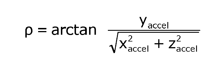

where xaccel, yaccel, and zaccel are measurements from the x, y and z-axes of the three-axis accelerometer. Pitch (Φ), roll (ρ) and angle (θ) of the z-axis relative to gravity can also be calculated by other means. - Although
surface 402 is described above as a horizontal surface, thesurface 402 that the device 102 is facing or resting on could be a non-horizontal surface (for example an angled podium rest). Accordingly, in at least some example embodiments, the location of thedevice 201 is determined relative to an initial position in which the display screen is in a stationary location adjacent to and facingsurface 402 and the initial position need not be a horizontal position. In some example embodiments thedevice 201 is configured to determine that the device is in an initial stationary position with its display screen resting against a surface by determining, after the motion is detected for a threshold time, if the light intensity measured by theIR sensors IR emitter 1602 activated and based on ambient IR readings without theIR emitter 1602 activated. In some example embodiments, in addition to using light intensity measurements, one or more of the pitch (Φ), roll (ρ) and z-axis (θ) angles (θ) are compared against pre-defined ranges in order to determine thatdevice 201 is in an initial resting position with its screen facing a surface. - Movement of the
device 201 from its initial position triggers thedevice 201 to estimate the reflectance index of the surface it is facing. In some example embodiments, thedevice 201 is configured to require a further trigger such as a pending message notification to activate the surface reflection estimation system. In some embodiments, the surface reflection estimation system discriminates between specific types or ranges of movement. For example, a tilting movement such as shown inFigure 6 of the device to a position with a tilt angle "a" within a predefined range for a predetermined duration will result in the surface reflection estimation system calculating the surface reflectance to determine if a reflective display mode is appropriate - however, the device will forgo the reflectance estimation if the orientation subsystem indicates an upward lifting of thedevice 201 in a horizontal position, or movement to an angle outside of the predetermined range. In some example embodiments, the brightness level or backlighting of the text displayed on thescreen 204 in reflection display mode is adjusted in dependence on the relative location of thedevice 201 as determined byorientation subsystem 249 to the reflectingsurface 402. For example, referring toFigures 6 to 9 , at a small tilt angle "a" as shown inFigure 6 the backlighting ofdisplay screen 204 is brighter than the backlighting used at a larger tilt angle "b" as shown inFigure 9 . In at least some uses, adjusting the brightness can provide greater privacy as the reflectingsurface 402 andscreen 204 are both more exposed to other persons at the wider angle "b" rather than tilt angle "a", thus the reduced brightness at angle "b" makes the image harder to view by third parties. In some example embodiments, the displayed text may be displayed as white characters and the background presented as black or dark in the reflective display mode - in such examples, the brightness of the characters could be decreased when moving from tilt angle "a" to "b". Similarly, the brightness could be adjusted in dependence on the reflectance index. In some example embodiments, the reflectance estimation system can be used to control features other than message notifications. For example, in some embodiments arrival of an incoming message or phone call or occurrence of a calendar or task event reminder, thedevice 201 may be configured to flash a ring border region or other region of thedisplay screen 204 to provide a notification of the new message or call or event reminder when a new event occurs while the device is in a face down position. In such embodiments, the display screen and device housing is configured so that sufficient light leaks out from the side edges of the device, either directly or from reflection off thesupport surface 204 such that the flashing can be visibly detected by a device user. In some examples, the flashed notification "ring" can be color coded to indicate the type of event the ring is being generated or the identity of the party from whom a new message or call is received from, or a combination of both. In some examples, the brightness of the flashed region can be determined in dependence on the reflectance index of the surface that the stationary device is laying on, with the reflectance index being determined based on the device position (as determined by the orientation subsystem 249) and light intensity sensors such as theIR sensors 1605A 1604B. In some examples, the brightness of the flashed region can be reduced on higher reflecting surfaces so as to be more discrete. In some example embodiments, the sensed light information that is combined with location information may be obtained by a camera sensor rather than one or more IR sensors, with the display screen or a forward facing camera flash used as a light emitter. - In some example embodiments, the tilt notification message display modes are applied such that privacy can be facilitated on a face-up
electronic device 201. In this regard,Figures 17-24 illustrate four display screen-up tilt-dependent display modes fordevice 201 that operate similar to the face-down display modes described above except for differences that will be apparent from the Figures and present description.Figure 17 showsdevice 201 in a stationary position, resting onsupport surface 402 withdisplay screen 204 facing upwards.Figure 18 shows front of thedisplay screen 204 in its face up position. Whenprocessor 240 detects a notification message trigger (a new email message in the illustrated embodiment) when thedevice 201 is in a stationary face up position theprocessor 240 causes a new notification message indicator to be generated - the new notification message indicator could take a form similar to that discussed above - for example a flashingLED 261 located on a visible surface of the device. However, as thedisplay screen 204 is visible it can alternatively or also be used in a face up display mode to provide a new message indicator, including for example by displaying abasic message 850 that indicates the type of new message that the new notification message is associated with but does not include any other content of thenew notification message 370. - The
processor 240 monitors the face updevice 201 to determine if thedevice 201 is tilted a threshold angle "A1" from its stationary position. In particular, referring to the embodiment ofFigure 17 , theprocessor 240 is effectively monitoring to see if adevice user 604 tilts the device upwards on thesupport surface 402. More specifically, based on input fromorientation subsystem 249, theprocessor 240 detects when thedevice 201 is tilted at least "A1" degrees relative to a horizontal axis that is parallel to the viewing surface of thedisplay screen 204. InFigure 19 , the tilt axis runs into the paper along the Y axis, and is generally along the device side edge 324 - thus theprocessor 204 monitors to determine if the edge of thedevice 201 that is furthest to a device user 604 (edge 322 inFigure 19 ) is being tilted up while the edge of the device closest to the user (edge 324 inFigure 19 ) remains substantially resting on thesupport surface 402. Once the threshold tilt angle "A1" is reached, theprocessor 240 causes selectedinformation 852 from thenotification message 370 to be displayed in a first notification message display mode on the display screen as shown inFigure 20 . In the example embodiment, the displayedinformation 852 includes the time field, message type field, and sender field information from the associatednotification message 370, but does not include the subject or content fields. - Referring to
Figures 21 and 22 , tilting thedevice 201 further to a threshold angle "B1" causes the displayed information to be modified and displayed in a second display mode. In particular, in the illustrated embodiment, the displayedinformation 854 inFigures 21 and 22 at tilt angle "B1" is the same as at the smaller tilt angle "A1", however the subject field information has been added. - In an example embodiment if the face up
device 201 is tilted to yet a further threshold tilt angle "C1" the displayed notification message information is modified again and displayed in a third display mode. In particular, referring toFigures 23 and 24 , theentire notification message 370 is displayed, such tha the content field is added to the displayed information. - Thus, the display screen up notification message viewing process described above allows a device user to discretely view notification messages and progress through a series of viewing modes that are dependent on the device tilt angle in order to control the manner and amount of information displayed by the
device 201. - By way of non limiting example, angle "A1" could be between 1 and 30 degrees; angle "B1" between 10 and 30 degrees greater than angle "A1"; and angle "C1" between 10 and 30 degrees greater than angle "B1". In some example embodiments, the threshold angles have can be user configured to vary from preset default values. In some example embodiments the starting position of the device may not be completely horizontal - for example the
device 201 could be face up on an angled podium. The threshold angles could in some embodiments be determined relative to the starting position or relative to a absolute horizontal or a combination thereof. - In at least some example embodiments the tilt-to view features described above enable a user to privately view message notifications with a minimum amount of device interaction as the user does not need to activate the
touchscreen overlay 206 orcontrol keys 260 to view a message notification. Accordingly, such features may in some applications reduce physical wear on the physical user interfaces of themobile communications device 201. - In some example embodiments, movements other than tilting movements could be switch between display modes.
- According to at least one example embodiment is a method of displaying notification message information on a display screen of a handheld electronic device that includes determining if the handheld electronic device is tilted a first threshold relative to a first orientation and displaying in response to the tilting at least some of the notification message information, and then determining if the handheld electronic device is tilted further to a second threshold and changing the display of the notification message information on the display screen in response to the further tilting.
- While the present disclosure is primarily described in terms of methods, a person of ordinary skill in the art will understand that the present disclosure is also directed to various apparatus such as a handheld electronic device including components for performing at least some of the aspects and features of the described methods, be it by way of hardware components, software or any combination of the two, or in any other manner. Moreover, an article of manufacture for use with the apparatus, such as a pre-recorded storage device or other similar computer readable medium including program instructions recorded thereon, or a computer data signal carrying computer readable program instructions may direct an apparatus to facilitate the practice of the described methods. It is understood that such apparatus, articles of manufacture, and computer data signals also come within the scope of the present disclosure.
- The term "computer readable medium" as used herein means any medium which can store instructions for use by or execution by a computer or other computing device including, but not limited to, a portable computer diskette, a hard disk drive (HDD), a random access memory (RAM), a read-only memory (ROM), an erasable programmable-read-only memory (EPROM) or flash memory, an optical disc such as a Compact Disc (CD), Digital Versatile Disc (DVD) or Blu-ray™ Disc, and a solid state storage device (e.g., NAND flash or synchronous dynamic RAM (SDRAM)).
- The various embodiments presented above are merely examples and are in no way meant to limit the scope of this disclosure. Variations of the innovations described herein will be apparent to persons of ordinary skill in the art, such variations being within the intended scope of the present application. In particular, features from one or more of the above-described embodiments may be selected to create alternative embodiments comprised of a subcombination of features which may not be explicitly described above. In addition, features from one or more of the above-described embodiments may be selected and combined to create alternative embodiments comprised of a combination of features which may not be explicitly described above. Features suitable for such combinations and sub-combinations would be readily apparent to persons skilled in the art upon review of the present application as a whole. The subject matter described herein and in the recited claims intends to cover and embrace all suitable changes in technology.
Claims (15)
- A method of estimating reflectance of a surface adjacent a handheld electronic device having an orientation sensor and a light sensor, comprising:estimating a location of the handheld electronic device relative to the surface in dependence on information from the orientation sensor;measuring light reflected from the surface with the light sensor; andestimating a reflectance of the surface in dependence on the estimated location and measured light.
- The method of claim 1 wherein estimating a location comprises estimating a distance of at least a portion of the handheld electronic device to the surface.
- The method of claim 3 wherein estimating a location comprises estimating a distance of the light sensor to the surface.
- The method of any one of claims 1 to 3 wherein estimating a location of the handheld electronic device relative to the surface comprises estimating a tilt angle of a display screen of the device relative to the surface.
- The method of any one of claims 1 to 4 wherein measuring light reflected from the surface comprises emitting light towards the surface from a light emitter located on the device.
- The method of claim 5 wherein the light emitter comprises an IR (infrared) emitter on the device.
- The method of claim 5 wherein the light emitter comprises a display screen of the device.
- The method of claim 5 wherein the light emitter comprises a camera flash of the device.
- The method of any one of claims 1 to 6 wherein the light sensor comprises an IR sensor.
- The method of claim 9 wherein the light sensor comprises a pair of IR sensors.
- The method of any one of claims 1 to 8 wherein the light sensor comprises a camera sensor.
- The method of any one of claims 1 to 11 comprising displaying information on a display screen of the device in dependence on the estimated reflectance.
- The method of claim 12 wherein one or more of an orientation, brightness or position of the displayed information is determined in dependence on the estimated reflectance
- The method of claim 13 wherein text is displayed so that its reflection can be viewed from the surface in dependence on the estimated reflectance.
- A handheld electronic device configured to perform the method of any one of claims 1 to 14.
Priority Applications (1)
| Application Number | Priority Date | Filing Date | Title |
|---|---|---|---|
| EP12194101.7A EP2736228B1 (en) | 2012-11-23 | 2012-11-23 | Handheld device with surface reflection estimation |
Applications Claiming Priority (1)
| Application Number | Priority Date | Filing Date | Title |
|---|---|---|---|
| EP12194101.7A EP2736228B1 (en) | 2012-11-23 | 2012-11-23 | Handheld device with surface reflection estimation |
Publications (2)
| Publication Number | Publication Date |
|---|---|
| EP2736228A1 true EP2736228A1 (en) | 2014-05-28 |
| EP2736228B1 EP2736228B1 (en) | 2017-11-08 |
Family
ID=47519827
Family Applications (1)
| Application Number | Title | Priority Date | Filing Date |
|---|---|---|---|
| EP12194101.7A Active EP2736228B1 (en) | 2012-11-23 | 2012-11-23 | Handheld device with surface reflection estimation |
Country Status (1)
| Country | Link |
|---|---|
| EP (1) | EP2736228B1 (en) |
Cited By (1)
| Publication number | Priority date | Publication date | Assignee | Title |
|---|---|---|---|---|
| CN106841118A (en) * | 2017-01-24 | 2017-06-13 | 清华大学 | Spectral measurement system and measuring method |
Citations (3)
| Publication number | Priority date | Publication date | Assignee | Title |
|---|---|---|---|---|
| US20020193080A1 (en) * | 2001-04-12 | 2002-12-19 | Asko Komsi | Movemet and attitude controlled mobile station control |
| US20080006762A1 (en) * | 2005-09-30 | 2008-01-10 | Fadell Anthony M | Integrated proximity sensor and light sensor |
| US20120133790A1 (en) * | 2010-11-29 | 2012-05-31 | Google Inc. | Mobile device image feedback |
-
2012
- 2012-11-23 EP EP12194101.7A patent/EP2736228B1/en active Active
Patent Citations (3)
| Publication number | Priority date | Publication date | Assignee | Title |
|---|---|---|---|---|
| US20020193080A1 (en) * | 2001-04-12 | 2002-12-19 | Asko Komsi | Movemet and attitude controlled mobile station control |
| US20080006762A1 (en) * | 2005-09-30 | 2008-01-10 | Fadell Anthony M | Integrated proximity sensor and light sensor |
| US20120133790A1 (en) * | 2010-11-29 | 2012-05-31 | Google Inc. | Mobile device image feedback |
Cited By (1)
| Publication number | Priority date | Publication date | Assignee | Title |
|---|---|---|---|---|
| CN106841118A (en) * | 2017-01-24 | 2017-06-13 | 清华大学 | Spectral measurement system and measuring method |
Also Published As
| Publication number | Publication date |
|---|---|
| EP2736228B1 (en) | 2017-11-08 |
Similar Documents
| Publication | Publication Date | Title |
|---|---|---|
| US10375220B2 (en) | Handheld device with notification message viewing | |
| US9012846B2 (en) | Handheld device with surface reflection estimation | |
| US10521111B2 (en) | Electronic apparatus and method for displaying a plurality of images in a plurality of areas of a display | |
| US20210333979A1 (en) | Devices, Methods, and Graphical User Interfaces for System-Wide Behavior for 3D Models | |
| US9602644B2 (en) | Method and apparatus for providing event of portable device having flexible display unit | |
| US20160291864A1 (en) | Method of interacting with a portable electronic device | |
| US20150145883A1 (en) | Altering attributes of content that is provided in a portion of a display area based on detected inputs | |
| US20140232634A1 (en) | Touch-based gestures modified by gyroscope and accelerometer | |
| US20130137483A1 (en) | Mobile terminal and controlling method of displaying direction | |
| EP2981874B1 (en) | Portable device providing a reflection image and method of controlling the same | |
| US20170003794A1 (en) | Electronic Device and Control Method Thereof | |
| US10424099B2 (en) | Specular highlights on photos of objects | |
| US20140228073A1 (en) | Automatic presentation of an image from a camera responsive to detection of a particular type of movement of a user device | |
| CA2865031A1 (en) | Handheld device with notification message viewing | |
| CA2757527A1 (en) | Motion gestures interface for portable electronic device | |
| EP2736228B1 (en) | Handheld device with surface reflection estimation | |
| US20200280623A1 (en) | Display screen switching method and mobile terminal |
Legal Events
| Date | Code | Title | Description |
|---|---|---|---|
| PUAI | Public reference made under article 153(3) epc to a published international application that has entered the european phase |
Free format text: ORIGINAL CODE: 0009012 |
|
| 17P | Request for examination filed |
Effective date: 20121123 |
|
| AK | Designated contracting states |
Kind code of ref document: A1 Designated state(s): AL AT BE BG CH CY CZ DE DK EE ES FI FR GB GR HR HU IE IS IT LI LT LU LV MC MK MT NL NO PL PT RO RS SE SI SK SM TR |
|
| AX | Request for extension of the european patent |
Extension state: BA ME |
|
| 17Q | First examination report despatched |
Effective date: 20160226 |
|
| GRAP | Despatch of communication of intention to grant a patent |
Free format text: ORIGINAL CODE: EPIDOSNIGR1 |
|
| INTG | Intention to grant announced |
Effective date: 20170526 |
|
| GRAS | Grant fee paid |
Free format text: ORIGINAL CODE: EPIDOSNIGR3 |
|
| GRAA | (expected) grant |
Free format text: ORIGINAL CODE: 0009210 |
|
| AK | Designated contracting states |
Kind code of ref document: B1 Designated state(s): AL AT BE BG CH CY CZ DE DK EE ES FI FR GB GR HR HU IE IS IT LI LT LU LV MC MK MT NL NO PL PT RO RS SE SI SK SM TR |
|
| REG | Reference to a national code |
Ref country code: GB Ref legal event code: FG4D |
|
| REG | Reference to a national code |
Ref country code: CH Ref legal event code: EP Ref country code: AT Ref legal event code: REF Ref document number: 945193 Country of ref document: AT Kind code of ref document: T Effective date: 20171115 |
|
| REG | Reference to a national code |
Ref country code: FR Ref legal event code: PLFP Year of fee payment: 6 |
|
| REG | Reference to a national code |
Ref country code: IE Ref legal event code: FG4D |
|
| REG | Reference to a national code |
Ref country code: DE Ref legal event code: R096 Ref document number: 602012039440 Country of ref document: DE |
|
| REG | Reference to a national code |
Ref country code: NL Ref legal event code: MP Effective date: 20171108 |
|
| REG | Reference to a national code |
Ref country code: LT Ref legal event code: MG4D |
|
| REG | Reference to a national code |
Ref country code: AT Ref legal event code: MK05 Ref document number: 945193 Country of ref document: AT Kind code of ref document: T Effective date: 20171108 |
|
| PG25 | Lapsed in a contracting state [announced via postgrant information from national office to epo] |
Ref country code: LT Free format text: LAPSE BECAUSE OF FAILURE TO SUBMIT A TRANSLATION OF THE DESCRIPTION OR TO PAY THE FEE WITHIN THE PRESCRIBED TIME-LIMIT Effective date: 20171108 Ref country code: NO Free format text: LAPSE BECAUSE OF FAILURE TO SUBMIT A TRANSLATION OF THE DESCRIPTION OR TO PAY THE FEE WITHIN THE PRESCRIBED TIME-LIMIT Effective date: 20180208 Ref country code: NL Free format text: LAPSE BECAUSE OF FAILURE TO SUBMIT A TRANSLATION OF THE DESCRIPTION OR TO PAY THE FEE WITHIN THE PRESCRIBED TIME-LIMIT Effective date: 20171108 Ref country code: SE Free format text: LAPSE BECAUSE OF FAILURE TO SUBMIT A TRANSLATION OF THE DESCRIPTION OR TO PAY THE FEE WITHIN THE PRESCRIBED TIME-LIMIT Effective date: 20171108 Ref country code: ES Free format text: LAPSE BECAUSE OF FAILURE TO SUBMIT A TRANSLATION OF THE DESCRIPTION OR TO PAY THE FEE WITHIN THE PRESCRIBED TIME-LIMIT Effective date: 20171108 Ref country code: FI Free format text: LAPSE BECAUSE OF FAILURE TO SUBMIT A TRANSLATION OF THE DESCRIPTION OR TO PAY THE FEE WITHIN THE PRESCRIBED TIME-LIMIT Effective date: 20171108 |
|
| PG25 | Lapsed in a contracting state [announced via postgrant information from national office to epo] |
Ref country code: IS Free format text: LAPSE BECAUSE OF FAILURE TO SUBMIT A TRANSLATION OF THE DESCRIPTION OR TO PAY THE FEE WITHIN THE PRESCRIBED TIME-LIMIT Effective date: 20180308 Ref country code: BG Free format text: LAPSE BECAUSE OF FAILURE TO SUBMIT A TRANSLATION OF THE DESCRIPTION OR TO PAY THE FEE WITHIN THE PRESCRIBED TIME-LIMIT Effective date: 20180208 Ref country code: RS Free format text: LAPSE BECAUSE OF FAILURE TO SUBMIT A TRANSLATION OF THE DESCRIPTION OR TO PAY THE FEE WITHIN THE PRESCRIBED TIME-LIMIT Effective date: 20171108 Ref country code: AT Free format text: LAPSE BECAUSE OF FAILURE TO SUBMIT A TRANSLATION OF THE DESCRIPTION OR TO PAY THE FEE WITHIN THE PRESCRIBED TIME-LIMIT Effective date: 20171108 Ref country code: GR Free format text: LAPSE BECAUSE OF FAILURE TO SUBMIT A TRANSLATION OF THE DESCRIPTION OR TO PAY THE FEE WITHIN THE PRESCRIBED TIME-LIMIT Effective date: 20180209 Ref country code: LV Free format text: LAPSE BECAUSE OF FAILURE TO SUBMIT A TRANSLATION OF THE DESCRIPTION OR TO PAY THE FEE WITHIN THE PRESCRIBED TIME-LIMIT Effective date: 20171108 Ref country code: HR Free format text: LAPSE BECAUSE OF FAILURE TO SUBMIT A TRANSLATION OF THE DESCRIPTION OR TO PAY THE FEE WITHIN THE PRESCRIBED TIME-LIMIT Effective date: 20171108 |
|
| PG25 | Lapsed in a contracting state [announced via postgrant information from national office to epo] |
Ref country code: DK Free format text: LAPSE BECAUSE OF FAILURE TO SUBMIT A TRANSLATION OF THE DESCRIPTION OR TO PAY THE FEE WITHIN THE PRESCRIBED TIME-LIMIT Effective date: 20171108 Ref country code: LI Free format text: LAPSE BECAUSE OF NON-PAYMENT OF DUE FEES Effective date: 20171130 Ref country code: CY Free format text: LAPSE BECAUSE OF FAILURE TO SUBMIT A TRANSLATION OF THE DESCRIPTION OR TO PAY THE FEE WITHIN THE PRESCRIBED TIME-LIMIT Effective date: 20171108 Ref country code: EE Free format text: LAPSE BECAUSE OF FAILURE TO SUBMIT A TRANSLATION OF THE DESCRIPTION OR TO PAY THE FEE WITHIN THE PRESCRIBED TIME-LIMIT Effective date: 20171108 Ref country code: CZ Free format text: LAPSE BECAUSE OF FAILURE TO SUBMIT A TRANSLATION OF THE DESCRIPTION OR TO PAY THE FEE WITHIN THE PRESCRIBED TIME-LIMIT Effective date: 20171108 Ref country code: CH Free format text: LAPSE BECAUSE OF NON-PAYMENT OF DUE FEES Effective date: 20171130 Ref country code: SK Free format text: LAPSE BECAUSE OF FAILURE TO SUBMIT A TRANSLATION OF THE DESCRIPTION OR TO PAY THE FEE WITHIN THE PRESCRIBED TIME-LIMIT Effective date: 20171108 |
|
| REG | Reference to a national code |
Ref country code: DE Ref legal event code: R097 Ref document number: 602012039440 Country of ref document: DE |
|
| PG25 | Lapsed in a contracting state [announced via postgrant information from national office to epo] |
Ref country code: PL Free format text: LAPSE BECAUSE OF FAILURE TO SUBMIT A TRANSLATION OF THE DESCRIPTION OR TO PAY THE FEE WITHIN THE PRESCRIBED TIME-LIMIT Effective date: 20171108 Ref country code: RO Free format text: LAPSE BECAUSE OF FAILURE TO SUBMIT A TRANSLATION OF THE DESCRIPTION OR TO PAY THE FEE WITHIN THE PRESCRIBED TIME-LIMIT Effective date: 20171108 Ref country code: IT Free format text: LAPSE BECAUSE OF FAILURE TO SUBMIT A TRANSLATION OF THE DESCRIPTION OR TO PAY THE FEE WITHIN THE PRESCRIBED TIME-LIMIT Effective date: 20171108 Ref country code: SM Free format text: LAPSE BECAUSE OF FAILURE TO SUBMIT A TRANSLATION OF THE DESCRIPTION OR TO PAY THE FEE WITHIN THE PRESCRIBED TIME-LIMIT Effective date: 20171108 Ref country code: LU Free format text: LAPSE BECAUSE OF NON-PAYMENT OF DUE FEES Effective date: 20171123 |
|
| REG | Reference to a national code |
Ref country code: BE Ref legal event code: MM Effective date: 20171130 |
|
| REG | Reference to a national code |
Ref country code: IE Ref legal event code: MM4A |
|
| PLBE | No opposition filed within time limit |
Free format text: ORIGINAL CODE: 0009261 |
|
| STAA | Information on the status of an ep patent application or granted ep patent |
Free format text: STATUS: NO OPPOSITION FILED WITHIN TIME LIMIT |
|
| PG25 | Lapsed in a contracting state [announced via postgrant information from national office to epo] |
Ref country code: MT Free format text: LAPSE BECAUSE OF NON-PAYMENT OF DUE FEES Effective date: 20171123 |
|
| 26N | No opposition filed |
Effective date: 20180809 |
|
| PG25 | Lapsed in a contracting state [announced via postgrant information from national office to epo] |
Ref country code: IE Free format text: LAPSE BECAUSE OF NON-PAYMENT OF DUE FEES Effective date: 20171123 |
|
| PG25 | Lapsed in a contracting state [announced via postgrant information from national office to epo] |
Ref country code: SI Free format text: LAPSE BECAUSE OF FAILURE TO SUBMIT A TRANSLATION OF THE DESCRIPTION OR TO PAY THE FEE WITHIN THE PRESCRIBED TIME-LIMIT Effective date: 20171108 Ref country code: BE Free format text: LAPSE BECAUSE OF NON-PAYMENT OF DUE FEES Effective date: 20171130 |
|
| PG25 | Lapsed in a contracting state [announced via postgrant information from national office to epo] |
Ref country code: MC Free format text: LAPSE BECAUSE OF FAILURE TO SUBMIT A TRANSLATION OF THE DESCRIPTION OR TO PAY THE FEE WITHIN THE PRESCRIBED TIME-LIMIT Effective date: 20171108 Ref country code: HU Free format text: LAPSE BECAUSE OF FAILURE TO SUBMIT A TRANSLATION OF THE DESCRIPTION OR TO PAY THE FEE WITHIN THE PRESCRIBED TIME-LIMIT; INVALID AB INITIO Effective date: 20121123 |
|
| PG25 | Lapsed in a contracting state [announced via postgrant information from national office to epo] |
Ref country code: MK Free format text: LAPSE BECAUSE OF FAILURE TO SUBMIT A TRANSLATION OF THE DESCRIPTION OR TO PAY THE FEE WITHIN THE PRESCRIBED TIME-LIMIT Effective date: 20171108 |
|
| PG25 | Lapsed in a contracting state [announced via postgrant information from national office to epo] |
Ref country code: TR Free format text: LAPSE BECAUSE OF FAILURE TO SUBMIT A TRANSLATION OF THE DESCRIPTION OR TO PAY THE FEE WITHIN THE PRESCRIBED TIME-LIMIT Effective date: 20171108 |
|
| PG25 | Lapsed in a contracting state [announced via postgrant information from national office to epo] |
Ref country code: PT Free format text: LAPSE BECAUSE OF FAILURE TO SUBMIT A TRANSLATION OF THE DESCRIPTION OR TO PAY THE FEE WITHIN THE PRESCRIBED TIME-LIMIT Effective date: 20171108 |
|
| PG25 | Lapsed in a contracting state [announced via postgrant information from national office to epo] |
Ref country code: AL Free format text: LAPSE BECAUSE OF FAILURE TO SUBMIT A TRANSLATION OF THE DESCRIPTION OR TO PAY THE FEE WITHIN THE PRESCRIBED TIME-LIMIT Effective date: 20171108 |
|
| REG | Reference to a national code |
Ref country code: DE Ref legal event code: R081 Ref document number: 602012039440 Country of ref document: DE Owner name: MALIKIE INNOVATIONS LTD., IE Free format text: FORMER OWNER: BLACKBERRY LIMITED, WATERLOO, ONTARIO, CA |
|
| REG | Reference to a national code |
Ref country code: GB Ref legal event code: 732E Free format text: REGISTERED BETWEEN 20240620 AND 20240627 |
|
| PGFP | Annual fee paid to national office [announced via postgrant information from national office to epo] |
Ref country code: DE Payment date: 20251126 Year of fee payment: 14 |
|
| PGFP | Annual fee paid to national office [announced via postgrant information from national office to epo] |
Ref country code: GB Payment date: 20251125 Year of fee payment: 14 |
|
| PGFP | Annual fee paid to national office [announced via postgrant information from national office to epo] |
Ref country code: FR Payment date: 20251125 Year of fee payment: 14 |