EP2736138B1 - Box for installing and wiring electrical devices - Google Patents
Box for installing and wiring electrical devices Download PDFInfo
- Publication number
- EP2736138B1 EP2736138B1 EP13005426.5A EP13005426A EP2736138B1 EP 2736138 B1 EP2736138 B1 EP 2736138B1 EP 13005426 A EP13005426 A EP 13005426A EP 2736138 B1 EP2736138 B1 EP 2736138B1
- Authority
- EP
- European Patent Office
- Prior art keywords
- box
- wall
- outer edge
- panel
- constituted
- Prior art date
- Legal status (The legal status is an assumption and is not a legal conclusion. Google has not performed a legal analysis and makes no representation as to the accuracy of the status listed.)
- Revoked
Links
- 238000009434 installation Methods 0.000 description 26
- 239000000463 material Substances 0.000 description 5
- 238000005192 partition Methods 0.000 description 5
- 210000000078 claw Anatomy 0.000 description 3
- 230000036961 partial effect Effects 0.000 description 3
- 230000000284 resting effect Effects 0.000 description 2
- 230000002159 abnormal effect Effects 0.000 description 1
- 239000004568 cement Substances 0.000 description 1
- 230000002860 competitive effect Effects 0.000 description 1
- 238000010276 construction Methods 0.000 description 1
- 238000000605 extraction Methods 0.000 description 1
- 230000002401 inhibitory effect Effects 0.000 description 1
- 230000037431 insertion Effects 0.000 description 1
- 238000003780 insertion Methods 0.000 description 1
- 239000011810 insulating material Substances 0.000 description 1
- 238000009413 insulation Methods 0.000 description 1
- 239000003562 lightweight material Substances 0.000 description 1
- 230000000670 limiting effect Effects 0.000 description 1
- 230000007246 mechanism Effects 0.000 description 1
- 239000002184 metal Substances 0.000 description 1
- 230000002093 peripheral effect Effects 0.000 description 1
- 230000000750 progressive effect Effects 0.000 description 1
- 238000010079 rubber tapping Methods 0.000 description 1
- 239000002699 waste material Substances 0.000 description 1
- 239000002023 wood Substances 0.000 description 1
Images


Classifications
-
- H—ELECTRICITY
- H02—GENERATION; CONVERSION OR DISTRIBUTION OF ELECTRIC POWER
- H02G—INSTALLATION OF ELECTRIC CABLES OR LINES, OR OF COMBINED OPTICAL AND ELECTRIC CABLES OR LINES
- H02G3/00—Installations of electric cables or lines or protective tubing therefor in or on buildings, equivalent structures or vehicles
- H02G3/02—Details
- H02G3/08—Distribution boxes; Connection or junction boxes
- H02G3/12—Distribution boxes; Connection or junction boxes for flush mounting
- H02G3/123—Distribution boxes; Connection or junction boxes for flush mounting in thin walls
Definitions
- the present invention relates to a box for installing and wiring electrical devices, studied particularly to be embedded, especially in hollow walls.
- junction box dedicated specifically to such type of wall.
- the first one is related to resistance to abnormal heat and to fire, which causes the need to use different materials with respect to those used in boxes of the traditional type.
- the second factor that entails the need to use dedicated boxes is linked to the different installation manner with respect to boxes used in walls of the traditional type.
- a wall of the light type in fact has a very low thickness and, once it has been perforated to make room for the box, allows a limited fixing region included between the outer and inner faces of the wall.
- the panel In a first type of installation, the panel is perforated in the position in which one wishes to install the box and the shape of the hole matches the dimensions of the box to be installed. Accordingly, the tubes intended to accommodate the wires, necessary for the power supply of the devices installed therein, are extracted from the interspace of the wall and arranged within the box, through the adapted openings provided in the rear of the box.
- the box is then inserted in the hole starting from the front of the wall. Once the tubes have been positioned, the box is fixed by virtue of screws that are applied again by acting from the outer side of the wall.
- This system is used predominantly with component boxes, where the construction of the box and the limited quantity of tubes, from one to three tubes, allow easy installation thereof.
- a second type of installation differs from the first one in that the box is mounted on the posts, generally made of metal, that are needed to support the wall.
- a cross-member generally constituted by material that is present in the building site for other purposes, is used and the box is rested thereon often in an unstable position that causes fixing to be rather complicated.
- the fixing screws are then fixed directly to the posts, which are easy to identify.
- the mounting of the box is performed before applying the front part of the wall.
- a third installation system is normally used when one wishes to renovate an existing building by adding a wall of the light type that is rested against a traditional wall.
- This type of installation is used for example both to ensure better thermal and acoustic insulation and to provide walls having a particular shape in order to give particular architectural characteristics to the room.
- This third installation system is performed in a manner that is substantially similar to the preceding case, i.e., by using the supporting frames of the light walls.
- the rear wall is no longer constituted by lightweight material but is a wall of the traditional type.
- the box is fixed to the traditional wall by virtue of systems suitable for the purpose, such as for example expansion plugs.
- junction boxes are generally unable to satisfy in a flexible manner all of the three installation systems described above.
- Some boxes of the conventional type are provided with lateral wings or claws that allow easy fixing in the first case, i.e., when mounting occurs in the presence of the previously perforated front panel; however, placement of the tubes inside the box is very difficult.
- the claws in fact are arranged in the interspace located between the rear wall and the front wall, resting on the inner side of the latter so as to prevent extraction of the box.
- the box can be used, but with great difficulty, since the claw resting surface is not provided.
- DE202004018083 discloses an electrical box having flange members for fastening the box to a surface.
- the box is suitable for insertion in a matching hole in a wall and is enclosed at the opening by a fire-inhibiting, especially non-flammable insulating material that is arranged between the hole soffit and box casing in the fitted position.
- DE1876074 discloses an electrical box provided with flange members cooperating with a front plate for fixing the box to a thin wall.
- US7045713 discloses a combination of electrical box and bushing wherein the box is mounted on the wall by means of slide members having a peripheral flange.
- US2011067320 discloses an in-wall component to be installed in a partition by attaching the wall component to a bracket mounted to a hole in the partition.
- the component is slightly recessed from the front of the partition to create a slight recess between the front of the partition and the front of the component.
- a component leveler could then be attached to the bracket to cover the in-wall component, providing a mount that is substantially flush to the wall.
- the component leveler has several adjustment mechanisms that operate independently of one another to adjust an angular depth of the component leveler to ensure that the edges of the component leveler are perfectly flush with the front of the partition.
- US6951983 discloses an outlet box assembly that simplifies the installation of an electrical box to a block wall.
- the assembly includes a box and a base plate.
- the box includes side arms projecting from the sidewalls in a plane parallel to the planar front.
- the side arms include one or more apertures for receipt of fasteners.
- the base plate is substantially larger in area than the sidewalls of the box and includes an opening therein sized to accept the sidewalls of the box.
- the box is secured to a block wall by creating a hole in the wall at the desired location, positioning the base plate over the hole and against the wall, placing the box through the opening in the base plate until the back surface of the arms are flush with the base plate, and driving fasteners through one or more of the apertures in the side arms, through the base plate, and into the cement block.
- the aim of the present invention is to provide a box for installing and wiring electrical devices that overcomes the drawbacks of the cited prior art.
- an object of the invention is to provide a box that is particularly advantageous in the case of embedded installation, especially in hollow walls.
- Another object of the invention is to provide a box that can be fixed easily to a hollow wall, by working from the front, after providing an opening adapted to accommodate it.
- Another object is to provide a box that can be fitted easily on supporting cross-members attached to the supporting structure of a light wall, before the front face of the light wall is applied to the posts of the wall.
- a further object of the present invention is to provide a box that can be installed easily on a wall of the traditional type, before the front panel of a light wall is applied.
- Another object of the present invention is to provide a structure which, by virtue of its particular constructive characteristics, is capable of giving the greatest assurances of reliability and safety in use.
- a further object of the present invention is to provide a structure that can be provided easily by using commonly commercially available elements and materials and is furthermore competitive from an economic standpoint.
- a box for installing and wiring electrical devices including a box-like body, which is open at the front and is constituted by a rear wall and by side walls that are mutually blended and are adapted to form a receptacle that is open at the front; the side walls including an outer edge that is formed on the front free edge of the side walls; the box-like body being adapted to be embedded in a hollow wall constituted by at least one panel provided with an opening; the box being characterized in that it includes fixing means constituted by discrete members associated with the outer edge and adapted to abut against a surface of a member of the wall at the opening.
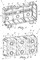
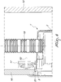
- the box for installing and wiring electrical devices includes a box-like body that is open at the front and is constituted by a rear wall 2 and by side walls 3 that are mutually blended.
- the rear wall 2 is quadrangular and the side walls 3 are blended with the rear wall 2 so as to form a substantially prism-like body, which forms a receptacle 4 that is open toward the front part of the box and is delimited by an outer edge 5, which in turn is formed on the free edge of the side walls 3.
- the box 1 has an abutment means constituted by discrete members associated with the outer edge 5.
- the discrete members are constituted by a plurality of wings 8 which are associated with the outer edge 5 and are extended substantially at right angles to the outer edge 5.
- the wings 8 are preferably retracted with respect to the front plane of the box formed by the outer edge 5.
- the box has four wings 8, two wings arranged on the upper side 6 of the outer edge 5 and two wings arranged on the lower side 7 of the outer edge 5.
- the front surfaces of the wings 8 form a plane that is parallel and retracted with respect to the front plane formed by the outer edge 5.
- An indicator member 9 is formed on the outer edge 5 at each wing 8 in order to allow to identify the position of the wing 8 during the mounting of the box.
- the indicator member 9 can be formed by a protrusion, a hollow or other member that is provided easily monolithically with the box.
- the box 1 also has abutments 51 that are adapted to cut into a panel 10 and guide the execution of the cut to provide an opening in the panel 10.
- the installation of the box 1 according to the present invention can be performed in various manners according to the requirements.
- Figures 3 and 4 illustrate the installation of the box on the rear side of a plasterboard wall.
- the box 1 is mounted on the rear side of a fixed panel 10 of a plasterboard wall 100 at an opening provided for this purpose in the panel 10.
- the abutments 51 provided on the outer edge 5 of the box 1, which are adapted to score the panel 10 and guide the execution of the cut to provide the opening of the box receptacle, are used.
- Installation is then completed by applying the movable panel 16 of the plasterboard wall 100.
- the wing 8 is spaced from the outer edge 5 of the box 1 so that the outer edge 5 does not protrude with respect to the outer surface of the fixed panel 10.
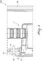
- Figures 5 and 6 illustrate the installation of the box 1 in the frame of a wall 100 with a fixed panel 10 made of plasterboard.
- the box 1 is rested against the cross-members 17 of the frame of the wall by using the rear flat region of the wings 8 and by fixing the box by virtue of self-tapping screws 52.
- the tubes 18 are then positioned within the box 1 and finally the movable panel 16 is fitted.
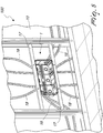
- Figure 7 illustrates a similar mounting system, where however the fixed part of the wall is constituted by a masonry wall 19 while the plasterboard movable panel is not visible because it is not installed yet.
- Figure 8 illustrates the installation of the box 1 in a wall constituted by a fixed masonry wall 19 and by a movable panel 20, in which the box 1 is fixed directly to the masonry wall 19, with the optional interposition of a shim, by virtue of expansion plugs 14 that engage the seats or slots 13 provided in the bottom 2 of the box 1.
- the invention achieves the intended aim and objects, providing a box for installing and wiring electrical devices studied particularly to be embedded in hollow walls, that is provided with wings for the abutment and fixing of the box to the internal surface of the outer panel of the wall or to the frame of the wall.
- the abutment wings of the present invention allow easier and faster installation of the box than boxes known up to now for use in hollow walls.
- the materials used, as well as the dimensions, may of course be any according to the requirements and the state of the art.
Landscapes
- Engineering & Computer Science (AREA)
- Architecture (AREA)
- Civil Engineering (AREA)
- Structural Engineering (AREA)
- Connection Or Junction Boxes (AREA)
- Control Of Electric Motors In General (AREA)
Description
- The present invention relates to a box for installing and wiring electrical devices, studied particularly to be embedded, especially in hollow walls.
- As is known, the increasing needs for flexibility, low cost and speed of execution are causing the progressive increase of buildings that use walls of the light type, for example made of plasterboard, instead of walls of the traditional type.
- Light walls in fact allow to intervene subsequently simply and cheaply by modifying the internal configuration of the rooms as a function of the changed requirements of their users.
- As is known, there are various types of junction box, dedicated specifically to such type of wall.
- This distinction is in fact necessary due to two factors.
- The first one is related to resistance to abnormal heat and to fire, which causes the need to use different materials with respect to those used in boxes of the traditional type.
- Such feature is due to the presence of an air duct that is constituted by the interspace between the two panels, which entails a higher risk with respect to possible ignition of the materials themselves.
- The second factor that entails the need to use dedicated boxes is linked to the different installation manner with respect to boxes used in walls of the traditional type.
- A wall of the light type in fact has a very low thickness and, once it has been perforated to make room for the box, allows a limited fixing region included between the outer and inner faces of the wall.
- In practice, at least three types of fixing systems are used.
- In a first type of installation, the panel is perforated in the position in which one wishes to install the box and the shape of the hole matches the dimensions of the box to be installed. Accordingly, the tubes intended to accommodate the wires, necessary for the power supply of the devices installed therein, are extracted from the interspace of the wall and arranged within the box, through the adapted openings provided in the rear of the box.
- The box is then inserted in the hole starting from the front of the wall. Once the tubes have been positioned, the box is fixed by virtue of screws that are applied again by acting from the outer side of the wall.
- This system is used predominantly with component boxes, where the construction of the box and the limited quantity of tubes, from one to three tubes, allow easy installation thereof.
- A second type of installation differs from the first one in that the box is mounted on the posts, generally made of metal, that are needed to support the wall. In particular, a cross-member, generally constituted by material that is present in the building site for other purposes, is used and the box is rested thereon often in an unstable position that causes fixing to be rather complicated. The fixing screws are then fixed directly to the posts, which are easy to identify. The mounting of the box is performed before applying the front part of the wall.
- A third installation system is normally used when one wishes to renovate an existing building by adding a wall of the light type that is rested against a traditional wall. This type of installation is used for example both to ensure better thermal and acoustic insulation and to provide walls having a particular shape in order to give particular architectural characteristics to the room. This third installation system is performed in a manner that is substantially similar to the preceding case, i.e., by using the supporting frames of the light walls.
- However, differently from the preceding case, the rear wall is no longer constituted by lightweight material but is a wall of the traditional type.
- Therefore, the box is fixed to the traditional wall by virtue of systems suitable for the purpose, such as for example expansion plugs.
- In such third type of installation the problem arises of making sure that the box that rests against the rear wall is not excessively recessed and therefore protrudes enough to ensure perfect planarity of the wall.
- In order to obviate this drawback, installation workers use waste material, such as pieces of cardboard and/or wood, which are rested against the rear of the box so as to form an additional thickness that allows to bring the outer surface of the box to a position that is suitable with respect to the outer surface of the wall.
- Commercially available junction boxes, however, are generally unable to satisfy in a flexible manner all of the three installation systems described above.
- Some boxes of the conventional type are provided with lateral wings or claws that allow easy fixing in the first case, i.e., when mounting occurs in the presence of the previously perforated front panel; however, placement of the tubes inside the box is very difficult.
- The claws in fact are arranged in the interspace located between the rear wall and the front wall, resting on the inner side of the latter so as to prevent extraction of the box.
- When the front panel is missing, as in the second and third installation systems, the box can be used, but with great difficulty, since the claw resting surface is not provided.
- Other boxes are known which are provided with slots that allow, if one uses the third installation system, to fix the box to the wall.
-
DE202004018083 discloses an electrical box having flange members for fastening the box to a surface. The box is suitable for insertion in a matching hole in a wall and is enclosed at the opening by a fire-inhibiting, especially non-flammable insulating material that is arranged between the hole soffit and box casing in the fitted position. -
DE1876074 discloses an electrical box provided with flange members cooperating with a front plate for fixing the box to a thin wall. -
US7045713 discloses a combination of electrical box and bushing wherein the box is mounted on the wall by means of slide members having a peripheral flange. -
US2011067320 discloses an in-wall component to be installed in a partition by attaching the wall component to a bracket mounted to a hole in the partition. The component is slightly recessed from the front of the partition to create a slight recess between the front of the partition and the front of the component. A component leveler could then be attached to the bracket to cover the in-wall component, providing a mount that is substantially flush to the wall. The component leveler has several adjustment mechanisms that operate independently of one another to adjust an angular depth of the component leveler to ensure that the edges of the component leveler are perfectly flush with the front of the partition. -
US6951983 discloses an outlet box assembly that simplifies the installation of an electrical box to a block wall. The assembly includes a box and a base plate. The box includes side arms projecting from the sidewalls in a plane parallel to the planar front. The side arms include one or more apertures for receipt of fasteners. The base plate is substantially larger in area than the sidewalls of the box and includes an opening therein sized to accept the sidewalls of the box. The box is secured to a block wall by creating a hole in the wall at the desired location, positioning the base plate over the hole and against the wall, placing the box through the opening in the base plate until the back surface of the arms are flush with the base plate, and driving fasteners through one or more of the apertures in the side arms, through the base plate, and into the cement block. - The aim of the present invention is to provide a box for installing and wiring electrical devices that overcomes the drawbacks of the cited prior art.
- Within the scope of this aim, an object of the invention is to provide a box that is particularly advantageous in the case of embedded installation, especially in hollow walls.
- Another object of the invention is to provide a box that can be fixed easily to a hollow wall, by working from the front, after providing an opening adapted to accommodate it.
- Another object is to provide a box that can be fitted easily on supporting cross-members attached to the supporting structure of a light wall, before the front face of the light wall is applied to the posts of the wall.
- A further object of the present invention is to provide a box that can be installed easily on a wall of the traditional type, before the front panel of a light wall is applied.
- Another object of the present invention is to provide a structure which, by virtue of its particular constructive characteristics, is capable of giving the greatest assurances of reliability and safety in use.
- A further object of the present invention is to provide a structure that can be provided easily by using commonly commercially available elements and materials and is furthermore competitive from an economic standpoint.
- This aim and these and other objects that will become better apparent hereinafter are achieved by a box for installing and wiring electrical devices, including a box-like body, which is open at the front and is constituted by a rear wall and by side walls that are mutually blended and are adapted to form a receptacle that is open at the front; the side walls including an outer edge that is formed on the front free edge of the side walls; the box-like body being adapted to be embedded in a hollow wall constituted by at least one panel provided with an opening; the box being characterized in that it includes fixing means constituted by discrete members associated with the outer edge and adapted to abut against a surface of a member of the wall at the opening.
- Further characteristics and advantages will become better apparent from the description of preferred but not exclusive embodiments of the invention, illustrated by way of non-limiting example in the accompanying drawings, wherein:
-
Figure 1 is a front perspective view of the junction box according to the present invention; -
Figure 2 is a perspective view of the rear side of the box of the preceding figure; -
Figure 3 is a schematic perspective view of the installation of the box on the fixed panel of a plasterboard wall; -
Figure 4 is a longitudinally sectional partial lateral elevation view of the installation of the box as in the preceding figure; -
Figure 5 is a schematic perspective view of the installation of the box on the frame of a plasterboard wall; -
Figure 6 is a longitudinally sectional partial lateral elevation view of the installation of the box as in the preceding figure; -
Figure 7 is a schematic perspective view of the installation of the box on the frame of a plasterboard wall, with a rear wall made of masonry; -
Figure 8 is a longitudinally sectional partial lateral elevation view of the installation of the box on the rear wall made of masonry. - With reference to the cited figures, the box for installing and wiring electrical devices, according to the invention, generally designated by the
reference numeral 1, includes a box-like body that is open at the front and is constituted by arear wall 2 and byside walls 3 that are mutually blended. - In the specific case, the
rear wall 2 is quadrangular and theside walls 3 are blended with therear wall 2 so as to form a substantially prism-like body, which forms areceptacle 4 that is open toward the front part of the box and is delimited by anouter edge 5, which in turn is formed on the free edge of theside walls 3. - According to the present invention, the
box 1 has an abutment means constituted by discrete members associated with theouter edge 5. - Advantageously, the discrete members are constituted by a plurality of
wings 8 which are associated with theouter edge 5 and are extended substantially at right angles to theouter edge 5. - The
wings 8 are preferably retracted with respect to the front plane of the box formed by theouter edge 5. - In the illustrated example, the box has four
wings 8, two wings arranged on theupper side 6 of theouter edge 5 and two wings arranged on thelower side 7 of theouter edge 5. - The front surfaces of the
wings 8 form a plane that is parallel and retracted with respect to the front plane formed by theouter edge 5. - An
indicator member 9 is formed on theouter edge 5 at eachwing 8 in order to allow to identify the position of thewing 8 during the mounting of the box. - The
indicator member 9 can be formed by a protrusion, a hollow or other member that is provided easily monolithically with the box. - The
box 1 also hasabutments 51 that are adapted to cut into apanel 10 and guide the execution of the cut to provide an opening in thepanel 10. - On the rear 2 of the
box 1 there are seats orslots 13 adapted to accommodate expansion plugs 14 for fixing the box to a wall. - The installation of the
box 1 according to the present invention can be performed in various manners according to the requirements. -
Figures 3 and4 illustrate the installation of the box on the rear side of a plasterboard wall. - The
box 1 is mounted on the rear side of a fixedpanel 10 of aplasterboard wall 100 at an opening provided for this purpose in thepanel 10. - In order to facilitate the opening of the box receptacle, the
abutments 51 provided on theouter edge 5 of thebox 1, which are adapted to score thepanel 10 and guide the execution of the cut to provide the opening of the box receptacle, are used. - Once the
box 1 has been rested within thepanel 10, at the opening, it is fixed permanently by virtue ofscrews 15 suitable for use on plasterboard. - Installation is then completed by applying the
movable panel 16 of theplasterboard wall 100. - Advantageously, as can be seen in the sectional view of
Figure 4 , thewing 8 is spaced from theouter edge 5 of thebox 1 so that theouter edge 5 does not protrude with respect to the outer surface of the fixedpanel 10. -
Figures 5 and6 illustrate the installation of thebox 1 in the frame of awall 100 with a fixedpanel 10 made of plasterboard. - The
box 1 is rested against the cross-members 17 of the frame of the wall by using the rear flat region of thewings 8 and by fixing the box by virtue of self-tappingscrews 52. - The
tubes 18 are then positioned within thebox 1 and finally themovable panel 16 is fitted. -
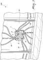
Figure 7 illustrates a similar mounting system, where however the fixed part of the wall is constituted by amasonry wall 19 while the plasterboard movable panel is not visible because it is not installed yet. -
Figure 8 illustrates the installation of thebox 1 in a wall constituted by a fixedmasonry wall 19 and by amovable panel 20, in which thebox 1 is fixed directly to themasonry wall 19, with the optional interposition of a shim, by virtue of expansion plugs 14 that engage the seats orslots 13 provided in thebottom 2 of thebox 1. - In practice it has been found that the invention achieves the intended aim and objects, providing a box for installing and wiring electrical devices studied particularly to be embedded in hollow walls, that is provided with wings for the abutment and fixing of the box to the internal surface of the outer panel of the wall or to the frame of the wall.
- The abutment wings of the present invention allow easier and faster installation of the box than boxes known up to now for use in hollow walls.
- The materials used, as well as the dimensions, may of course be any according to the requirements and the state of the art.
Claims (3)
- A box for installing and wiring electrical devices, comprising a box-like body which is open at the front and is constituted by a rear wall (2) and by side walls (3) that are mutually blended and are adapted to form a receptacle (4) that is open at the front; said side walls (3) comprising an outer edge (5) that is formed on the front free edge of said side walls (3); said box-like body being adapted to be embedded in a hollow wall (100) constituted by at least one panel (10) provided with an opening; said box further comprising fixing means constituted by discrete members (8) associated with said outer edge (5) and adapted to abut against a surface of a member of said wall at said opening;
said discrete members being constituted by a plurality of wings (8) associated with said outer edge (5) and extended substantially at right angles to said outer edge (5);
said wings (8) having front surfaces, said front surfaces forming a plane that is parallel and recessed with respect to a front plane defined by said outer edge (5); said
box being characterized in that it comprises an indicator member (9) that is formed on said outer edge (5), at each one of said wings (8), said indicator member (9) allowing to identify the position of said wing (8) during the mounting of the box; said box-like body comprises abutments (51) adapted to score a panel (10) of a wall (100) and to guide the execution of the cut to provide said opening in said panel (10). - The box according to claim 1, characterized in that said indicator member (9) is formed by a protrusion, recess or other member provided monolithically with said box-like body.
- The box according to claim 1, characterized in that said rear wall (2) comprises seats or slots (13) adapted to accommodate expansion plugs in order to allow the fixing of the box to a wall (19).
Applications Claiming Priority (1)
| Application Number | Priority Date | Filing Date | Title |
|---|---|---|---|
| IT001981A ITMI20121981A1 (en) | 2012-11-21 | 2012-11-21 | BOX FOR INSTALLATION AND WIRING OF ELECTRICAL DEVICES |
Publications (2)
| Publication Number | Publication Date |
|---|---|
| EP2736138A1 EP2736138A1 (en) | 2014-05-28 |
| EP2736138B1 true EP2736138B1 (en) | 2018-02-21 |
Family
ID=47631665
Family Applications (1)
| Application Number | Title | Priority Date | Filing Date |
|---|---|---|---|
| EP13005426.5A Revoked EP2736138B1 (en) | 2012-11-21 | 2013-11-19 | Box for installing and wiring electrical devices |
Country Status (3)
| Country | Link |
|---|---|
| EP (1) | EP2736138B1 (en) |
| ES (1) | ES2667321T3 (en) |
| IT (1) | ITMI20121981A1 (en) |
Families Citing this family (2)
| Publication number | Priority date | Publication date | Assignee | Title |
|---|---|---|---|---|
| ITUA20151263A1 (en) * | 2015-12-29 | 2017-06-29 | Vincenzo Torretta | DEVICE TO BE INSTALLED ON THE WALL TO "STAY" INSIDE THE HANDLE OF A HINGED SATIN DOOR / WALL, DURING OPENING, AND THEREFORE ALLOW IT TO BE COMPLETED ON IT. |
| IT201800001528A1 (en) * | 2018-01-19 | 2019-07-19 | Vimar Spa | WALL MOUNTABLE JUNCTION BOX FOR ELECTRICAL SYSTEMS |
Citations (21)
| Publication number | Priority date | Publication date | Assignee | Title |
|---|---|---|---|---|
| US2775812A (en) | 1953-10-15 | 1957-01-01 | Howard E Mohr | Method of locating apertures for electrical outlet boxes in wallboard and means useful therein |
| GB816738A (en) | 1956-07-24 | 1959-07-15 | F C Blackwell & Company Ltd | Improvements in and relating to electrical switch, socket, or like wall boxes |
| DE1876074U (en) | 1961-10-06 | 1963-07-25 | Ver Baustoffwerke Bodenwerder | SOCKET, SWITCH OD. THE LIKE, IN PARTICULAR FOR INSTALLATION IN PLASTERBOARD BOARDS. |
| US3633782A (en) | 1970-03-16 | 1972-01-11 | Alvin R Bellinger | Knockout box for an electrical switch and receptacle |
| US3940857A (en) | 1974-06-12 | 1976-03-02 | Giordano Anthony J | Cut-out locations marking method, means, and method of forming said means |
| DE2936963A1 (en) | 1979-09-13 | 1981-04-02 | Günther Spelsberg KG, 5885 Schalksmühle | Wall socket with cable in prefabricated wall - has window and support brackets, and support pins and adjustable bracket in body of socket |
| US4907711A (en) | 1988-11-04 | 1990-03-13 | Stuchlik Iii Charles F | Outlet box covers with location indicators for wall covering |
| US4953733A (en) | 1989-11-28 | 1990-09-04 | Loscuito Gaetano R | Electrical outlet box marking device |
| DE202004018083U1 (en) | 2004-11-22 | 2005-05-04 | Kaiser Gmbh & Co. Kommanditgesellschaft | Installation box for electrotechnical purposes for fitting in fire-inhibiting walls is enclosed near/at opening by fire-inhibiting, especially non-flammable insulating material arranged between hole soffit and box casing in fitted position |
| US6903272B2 (en) | 2003-11-05 | 2005-06-07 | Thomas & Betts International, Inc. | Gangable electrical box |
| US6951983B1 (en) * | 2004-06-30 | 2005-10-04 | Arlington Industries, Inc. | Outlet box assembly |
| US20050230142A1 (en) | 2004-04-14 | 2005-10-20 | Thomas & Betts International, Inc. | Electrical closure apparatus having wall impression members |
| US7045713B1 (en) | 2004-06-09 | 2006-05-16 | Arlington Industries, Inc. | Electrical box and bushing combination for providing electrical service on a block wall |
| EP1775815A2 (en) | 2005-10-12 | 2007-04-18 | Legrand France | Flush-mounted box with optimal fixation |
| GB2441139A (en) | 2006-08-21 | 2008-02-27 | Stephen Richards | Wallboard marking device indicating position of wall fixture |
| US20080073100A1 (en) | 2006-09-21 | 2008-03-27 | Hubbell Incorporated | Electrical box assembly |
| US7554032B2 (en) | 2006-12-15 | 2009-06-30 | Greg Herth | Electrical box with multi-mount features |
| GB2457776A (en) | 2008-03-01 | 2009-09-02 | Robert Foster | Plasterboard marking tool |
| EP2166633A2 (en) | 2008-08-25 | 2010-03-24 | Russound/FMP Incorporated | Back box with power pocket for in-wall electronic components |
| US20110067320A1 (en) * | 2006-09-11 | 2011-03-24 | Raymond Lee Call | Wall-Mount Adjustment Systems And Methods |
| US20110239477A1 (en) | 2010-04-01 | 2011-10-06 | Dressel Designs, Llc | Receptacle having integrally formed protrusions for marking |
-
2012
- 2012-11-21 IT IT001981A patent/ITMI20121981A1/en unknown
-
2013
- 2013-11-19 ES ES13005426.5T patent/ES2667321T3/en active Active
- 2013-11-19 EP EP13005426.5A patent/EP2736138B1/en not_active Revoked
Patent Citations (21)
| Publication number | Priority date | Publication date | Assignee | Title |
|---|---|---|---|---|
| US2775812A (en) | 1953-10-15 | 1957-01-01 | Howard E Mohr | Method of locating apertures for electrical outlet boxes in wallboard and means useful therein |
| GB816738A (en) | 1956-07-24 | 1959-07-15 | F C Blackwell & Company Ltd | Improvements in and relating to electrical switch, socket, or like wall boxes |
| DE1876074U (en) | 1961-10-06 | 1963-07-25 | Ver Baustoffwerke Bodenwerder | SOCKET, SWITCH OD. THE LIKE, IN PARTICULAR FOR INSTALLATION IN PLASTERBOARD BOARDS. |
| US3633782A (en) | 1970-03-16 | 1972-01-11 | Alvin R Bellinger | Knockout box for an electrical switch and receptacle |
| US3940857A (en) | 1974-06-12 | 1976-03-02 | Giordano Anthony J | Cut-out locations marking method, means, and method of forming said means |
| DE2936963A1 (en) | 1979-09-13 | 1981-04-02 | Günther Spelsberg KG, 5885 Schalksmühle | Wall socket with cable in prefabricated wall - has window and support brackets, and support pins and adjustable bracket in body of socket |
| US4907711A (en) | 1988-11-04 | 1990-03-13 | Stuchlik Iii Charles F | Outlet box covers with location indicators for wall covering |
| US4953733A (en) | 1989-11-28 | 1990-09-04 | Loscuito Gaetano R | Electrical outlet box marking device |
| US6903272B2 (en) | 2003-11-05 | 2005-06-07 | Thomas & Betts International, Inc. | Gangable electrical box |
| US20050230142A1 (en) | 2004-04-14 | 2005-10-20 | Thomas & Betts International, Inc. | Electrical closure apparatus having wall impression members |
| US7045713B1 (en) | 2004-06-09 | 2006-05-16 | Arlington Industries, Inc. | Electrical box and bushing combination for providing electrical service on a block wall |
| US6951983B1 (en) * | 2004-06-30 | 2005-10-04 | Arlington Industries, Inc. | Outlet box assembly |
| DE202004018083U1 (en) | 2004-11-22 | 2005-05-04 | Kaiser Gmbh & Co. Kommanditgesellschaft | Installation box for electrotechnical purposes for fitting in fire-inhibiting walls is enclosed near/at opening by fire-inhibiting, especially non-flammable insulating material arranged between hole soffit and box casing in fitted position |
| EP1775815A2 (en) | 2005-10-12 | 2007-04-18 | Legrand France | Flush-mounted box with optimal fixation |
| GB2441139A (en) | 2006-08-21 | 2008-02-27 | Stephen Richards | Wallboard marking device indicating position of wall fixture |
| US20110067320A1 (en) * | 2006-09-11 | 2011-03-24 | Raymond Lee Call | Wall-Mount Adjustment Systems And Methods |
| US20080073100A1 (en) | 2006-09-21 | 2008-03-27 | Hubbell Incorporated | Electrical box assembly |
| US7554032B2 (en) | 2006-12-15 | 2009-06-30 | Greg Herth | Electrical box with multi-mount features |
| GB2457776A (en) | 2008-03-01 | 2009-09-02 | Robert Foster | Plasterboard marking tool |
| EP2166633A2 (en) | 2008-08-25 | 2010-03-24 | Russound/FMP Incorporated | Back box with power pocket for in-wall electronic components |
| US20110239477A1 (en) | 2010-04-01 | 2011-10-06 | Dressel Designs, Llc | Receptacle having integrally formed protrusions for marking |
Non-Patent Citations (1)
| Title |
|---|
| ANONYMOUS: "BOXME Spit EcoFast", ITW CONSTRUCTION PRODUCTS - CATALOGUE, 8 February 2011 (2011-02-08), XP055535215 |
Also Published As
| Publication number | Publication date |
|---|---|
| ES2667321T3 (en) | 2018-05-10 |
| EP2736138A1 (en) | 2014-05-28 |
| ITMI20121981A1 (en) | 2014-05-22 |
Similar Documents
| Publication | Publication Date | Title |
|---|---|---|
| CN109306969B (en) | Ventilation fan containment and mounting system | |
| US8839578B2 (en) | Flush mount panels with multiple aligned receiving brackets | |
| US20030177724A1 (en) | H-shaped boot-to-register cover mounting adapter | |
| US9807482B2 (en) | Flat panel speaker or other device mount and installation method | |
| US20130312997A1 (en) | Electrical box | |
| US20150240477A1 (en) | Apparatus for securing insulation panels to a supporting structure and ceiling support assembly incorporating the same | |
| KR100946912B1 (en) | Wall construction method for insulation and fire prevention | |
| US20120186871A1 (en) | Adjustable electrical box | |
| EP2736138B1 (en) | Box for installing and wiring electrical devices | |
| RU2599391C2 (en) | Set of parts for mounting window lining and method of window lining with its application | |
| CN109098401B (en) | a decoration component | |
| WO2021017769A1 (en) | Mounting assembly for air conditioner indoor unit | |
| EP2851623B1 (en) | A mounting plate for an indoor unit of an air conditioner and a method of mouting an indoor unit | |
| GB2607559A (en) | Mounting electrical fittings in walls | |
| AU2017101778B4 (en) | A firestopping device and associated method | |
| JP3046565U (en) | Interior partition walls of buildings | |
| RU213303U1 (en) | Device for soundproofing the socket of an electrical installation device | |
| JP2008050929A (en) | Wall panel | |
| US20150276123A1 (en) | Adjustable mounting bracket and support | |
| JP2016176312A (en) | Adiabatic wall substrate structure | |
| GB2524328A (en) | An insulation wall system | |
| PT1726729E (en) | Partition wall for integrating with concrete floor | |
| JPH1176107A (en) | Toilet wall panel toilet exclusive room and manufacture of toilet exclusive room | |
| GB2510209A (en) | Non load bearing wall with wiring channels | |
| EP4658873A1 (en) | Bracket for walls |
Legal Events
| Date | Code | Title | Description |
|---|---|---|---|
| PUAI | Public reference made under article 153(3) epc to a published international application that has entered the european phase |
Free format text: ORIGINAL CODE: 0009012 |
|
| 17P | Request for examination filed |
Effective date: 20131119 |
|
| AK | Designated contracting states |
Kind code of ref document: A1 Designated state(s): AL AT BE BG CH CY CZ DE DK EE ES FI FR GB GR HR HU IE IS IT LI LT LU LV MC MK MT NL NO PL PT RO RS SE SI SK SM TR |
|
| AX | Request for extension of the european patent |
Extension state: BA ME |
|
| R17P | Request for examination filed (corrected) |
Effective date: 20141121 |
|
| RBV | Designated contracting states (corrected) |
Designated state(s): AL AT BE BG CH CY CZ DE DK EE ES FI FR GB GR HR HU IE IS IT LI LT LU LV MC MK MT NL NO PL PT RO RS SE SI SK SM TR |
|
| 17Q | First examination report despatched |
Effective date: 20150720 |
|
| STAA | Information on the status of an ep patent application or granted ep patent |
Free format text: STATUS: EXAMINATION IS IN PROGRESS |
|
| GRAP | Despatch of communication of intention to grant a patent |
Free format text: ORIGINAL CODE: EPIDOSNIGR1 |
|
| STAA | Information on the status of an ep patent application or granted ep patent |
Free format text: STATUS: GRANT OF PATENT IS INTENDED |
|
| INTG | Intention to grant announced |
Effective date: 20171013 |
|
| GRAS | Grant fee paid |
Free format text: ORIGINAL CODE: EPIDOSNIGR3 |
|
| GRAA | (expected) grant |
Free format text: ORIGINAL CODE: 0009210 |
|
| STAA | Information on the status of an ep patent application or granted ep patent |
Free format text: STATUS: THE PATENT HAS BEEN GRANTED |
|
| AK | Designated contracting states |
Kind code of ref document: B1 Designated state(s): AL AT BE BG CH CY CZ DE DK EE ES FI FR GB GR HR HU IE IS IT LI LT LU LV MC MK MT NL NO PL PT RO RS SE SI SK SM TR |
|
| REG | Reference to a national code |
Ref country code: GB Ref legal event code: FG4D |
|
| REG | Reference to a national code |
Ref country code: CH Ref legal event code: EP |
|
| REG | Reference to a national code |
Ref country code: AT Ref legal event code: REF Ref document number: 972701 Country of ref document: AT Kind code of ref document: T Effective date: 20180315 |
|
| REG | Reference to a national code |
Ref country code: IE Ref legal event code: FG4D |
|
| REG | Reference to a national code |
Ref country code: DE Ref legal event code: R096 Ref document number: 602013033243 Country of ref document: DE |
|
| REG | Reference to a national code |
Ref country code: ES Ref legal event code: FG2A Ref document number: 2667321 Country of ref document: ES Kind code of ref document: T3 Effective date: 20180510 |
|
| REG | Reference to a national code |
Ref country code: NL Ref legal event code: MP Effective date: 20180221 |
|
| REG | Reference to a national code |
Ref country code: LT Ref legal event code: MG4D |
|
| REG | Reference to a national code |
Ref country code: AT Ref legal event code: MK05 Ref document number: 972701 Country of ref document: AT Kind code of ref document: T Effective date: 20180221 |
|
| PG25 | Lapsed in a contracting state [announced via postgrant information from national office to epo] |
Ref country code: NO Free format text: LAPSE BECAUSE OF FAILURE TO SUBMIT A TRANSLATION OF THE DESCRIPTION OR TO PAY THE FEE WITHIN THE PRESCRIBED TIME-LIMIT Effective date: 20180521 Ref country code: FI Free format text: LAPSE BECAUSE OF FAILURE TO SUBMIT A TRANSLATION OF THE DESCRIPTION OR TO PAY THE FEE WITHIN THE PRESCRIBED TIME-LIMIT Effective date: 20180221 Ref country code: CY Free format text: LAPSE BECAUSE OF FAILURE TO SUBMIT A TRANSLATION OF THE DESCRIPTION OR TO PAY THE FEE WITHIN THE PRESCRIBED TIME-LIMIT Effective date: 20180221 Ref country code: NL Free format text: LAPSE BECAUSE OF FAILURE TO SUBMIT A TRANSLATION OF THE DESCRIPTION OR TO PAY THE FEE WITHIN THE PRESCRIBED TIME-LIMIT Effective date: 20180221 Ref country code: HR Free format text: LAPSE BECAUSE OF FAILURE TO SUBMIT A TRANSLATION OF THE DESCRIPTION OR TO PAY THE FEE WITHIN THE PRESCRIBED TIME-LIMIT Effective date: 20180221 Ref country code: LT Free format text: LAPSE BECAUSE OF FAILURE TO SUBMIT A TRANSLATION OF THE DESCRIPTION OR TO PAY THE FEE WITHIN THE PRESCRIBED TIME-LIMIT Effective date: 20180221 |
|
| PG25 | Lapsed in a contracting state [announced via postgrant information from national office to epo] |
Ref country code: GR Free format text: LAPSE BECAUSE OF FAILURE TO SUBMIT A TRANSLATION OF THE DESCRIPTION OR TO PAY THE FEE WITHIN THE PRESCRIBED TIME-LIMIT Effective date: 20180522 Ref country code: LV Free format text: LAPSE BECAUSE OF FAILURE TO SUBMIT A TRANSLATION OF THE DESCRIPTION OR TO PAY THE FEE WITHIN THE PRESCRIBED TIME-LIMIT Effective date: 20180221 Ref country code: SE Free format text: LAPSE BECAUSE OF FAILURE TO SUBMIT A TRANSLATION OF THE DESCRIPTION OR TO PAY THE FEE WITHIN THE PRESCRIBED TIME-LIMIT Effective date: 20180221 Ref country code: AT Free format text: LAPSE BECAUSE OF FAILURE TO SUBMIT A TRANSLATION OF THE DESCRIPTION OR TO PAY THE FEE WITHIN THE PRESCRIBED TIME-LIMIT Effective date: 20180221 Ref country code: RS Free format text: LAPSE BECAUSE OF FAILURE TO SUBMIT A TRANSLATION OF THE DESCRIPTION OR TO PAY THE FEE WITHIN THE PRESCRIBED TIME-LIMIT Effective date: 20180221 Ref country code: BG Free format text: LAPSE BECAUSE OF FAILURE TO SUBMIT A TRANSLATION OF THE DESCRIPTION OR TO PAY THE FEE WITHIN THE PRESCRIBED TIME-LIMIT Effective date: 20180521 |
|
| PG25 | Lapsed in a contracting state [announced via postgrant information from national office to epo] |
Ref country code: PL Free format text: LAPSE BECAUSE OF FAILURE TO SUBMIT A TRANSLATION OF THE DESCRIPTION OR TO PAY THE FEE WITHIN THE PRESCRIBED TIME-LIMIT Effective date: 20180221 Ref country code: AL Free format text: LAPSE BECAUSE OF FAILURE TO SUBMIT A TRANSLATION OF THE DESCRIPTION OR TO PAY THE FEE WITHIN THE PRESCRIBED TIME-LIMIT Effective date: 20180221 Ref country code: EE Free format text: LAPSE BECAUSE OF FAILURE TO SUBMIT A TRANSLATION OF THE DESCRIPTION OR TO PAY THE FEE WITHIN THE PRESCRIBED TIME-LIMIT Effective date: 20180221 Ref country code: RO Free format text: LAPSE BECAUSE OF FAILURE TO SUBMIT A TRANSLATION OF THE DESCRIPTION OR TO PAY THE FEE WITHIN THE PRESCRIBED TIME-LIMIT Effective date: 20180221 |
|
| REG | Reference to a national code |
Ref country code: DE Ref legal event code: R026 Ref document number: 602013033243 Country of ref document: DE |
|
| PG25 | Lapsed in a contracting state [announced via postgrant information from national office to epo] |
Ref country code: CZ Free format text: LAPSE BECAUSE OF FAILURE TO SUBMIT A TRANSLATION OF THE DESCRIPTION OR TO PAY THE FEE WITHIN THE PRESCRIBED TIME-LIMIT Effective date: 20180221 Ref country code: DK Free format text: LAPSE BECAUSE OF FAILURE TO SUBMIT A TRANSLATION OF THE DESCRIPTION OR TO PAY THE FEE WITHIN THE PRESCRIBED TIME-LIMIT Effective date: 20180221 Ref country code: SM Free format text: LAPSE BECAUSE OF FAILURE TO SUBMIT A TRANSLATION OF THE DESCRIPTION OR TO PAY THE FEE WITHIN THE PRESCRIBED TIME-LIMIT Effective date: 20180221 Ref country code: SK Free format text: LAPSE BECAUSE OF FAILURE TO SUBMIT A TRANSLATION OF THE DESCRIPTION OR TO PAY THE FEE WITHIN THE PRESCRIBED TIME-LIMIT Effective date: 20180221 |
|
| PLBI | Opposition filed |
Free format text: ORIGINAL CODE: 0009260 |
|
| PLAX | Notice of opposition and request to file observation + time limit sent |
Free format text: ORIGINAL CODE: EPIDOSNOBS2 |
|
| 26 | Opposition filed |
Opponent name: VIMAR S.P.A. Effective date: 20181121 |
|
| PG25 | Lapsed in a contracting state [announced via postgrant information from national office to epo] |
Ref country code: SI Free format text: LAPSE BECAUSE OF FAILURE TO SUBMIT A TRANSLATION OF THE DESCRIPTION OR TO PAY THE FEE WITHIN THE PRESCRIBED TIME-LIMIT Effective date: 20180221 |
|
| PLBB | Reply of patent proprietor to notice(s) of opposition received |
Free format text: ORIGINAL CODE: EPIDOSNOBS3 |
|
| REG | Reference to a national code |
Ref country code: CH Ref legal event code: PL |
|
| PG25 | Lapsed in a contracting state [announced via postgrant information from national office to epo] |
Ref country code: LU Free format text: LAPSE BECAUSE OF NON-PAYMENT OF DUE FEES Effective date: 20181119 Ref country code: MC Free format text: LAPSE BECAUSE OF FAILURE TO SUBMIT A TRANSLATION OF THE DESCRIPTION OR TO PAY THE FEE WITHIN THE PRESCRIBED TIME-LIMIT Effective date: 20180221 |
|
| REG | Reference to a national code |
Ref country code: BE Ref legal event code: MM Effective date: 20181130 |
|
| REG | Reference to a national code |
Ref country code: IE Ref legal event code: MM4A |
|
| PG25 | Lapsed in a contracting state [announced via postgrant information from national office to epo] |
Ref country code: CH Free format text: LAPSE BECAUSE OF NON-PAYMENT OF DUE FEES Effective date: 20181130 Ref country code: LI Free format text: LAPSE BECAUSE OF NON-PAYMENT OF DUE FEES Effective date: 20181130 |
|
| PG25 | Lapsed in a contracting state [announced via postgrant information from national office to epo] |
Ref country code: IE Free format text: LAPSE BECAUSE OF NON-PAYMENT OF DUE FEES Effective date: 20181119 |
|
| PG25 | Lapsed in a contracting state [announced via postgrant information from national office to epo] |
Ref country code: BE Free format text: LAPSE BECAUSE OF NON-PAYMENT OF DUE FEES Effective date: 20181130 |
|
| PG25 | Lapsed in a contracting state [announced via postgrant information from national office to epo] |
Ref country code: MT Free format text: LAPSE BECAUSE OF NON-PAYMENT OF DUE FEES Effective date: 20181119 |
|
| PG25 | Lapsed in a contracting state [announced via postgrant information from national office to epo] |
Ref country code: TR Free format text: LAPSE BECAUSE OF FAILURE TO SUBMIT A TRANSLATION OF THE DESCRIPTION OR TO PAY THE FEE WITHIN THE PRESCRIBED TIME-LIMIT Effective date: 20180221 |
|
| PG25 | Lapsed in a contracting state [announced via postgrant information from national office to epo] |
Ref country code: PT Free format text: LAPSE BECAUSE OF FAILURE TO SUBMIT A TRANSLATION OF THE DESCRIPTION OR TO PAY THE FEE WITHIN THE PRESCRIBED TIME-LIMIT Effective date: 20180221 |
|
| PG25 | Lapsed in a contracting state [announced via postgrant information from national office to epo] |
Ref country code: MK Free format text: LAPSE BECAUSE OF NON-PAYMENT OF DUE FEES Effective date: 20180221 Ref country code: HU Free format text: LAPSE BECAUSE OF FAILURE TO SUBMIT A TRANSLATION OF THE DESCRIPTION OR TO PAY THE FEE WITHIN THE PRESCRIBED TIME-LIMIT; INVALID AB INITIO Effective date: 20131119 |
|
| PG25 | Lapsed in a contracting state [announced via postgrant information from national office to epo] |
Ref country code: IS Free format text: LAPSE BECAUSE OF FAILURE TO SUBMIT A TRANSLATION OF THE DESCRIPTION OR TO PAY THE FEE WITHIN THE PRESCRIBED TIME-LIMIT Effective date: 20180621 |
|
| REG | Reference to a national code |
Ref country code: DE Ref legal event code: R103 Ref document number: 602013033243 Country of ref document: DE Ref country code: DE Ref legal event code: R064 Ref document number: 602013033243 Country of ref document: DE |
|
| RDAF | Communication despatched that patent is revoked |
Free format text: ORIGINAL CODE: EPIDOSNREV1 |
|
| PGFP | Annual fee paid to national office [announced via postgrant information from national office to epo] |
Ref country code: GB Payment date: 20211129 Year of fee payment: 9 Ref country code: ES Payment date: 20211201 Year of fee payment: 9 Ref country code: FR Payment date: 20211124 Year of fee payment: 9 Ref country code: DE Payment date: 20211126 Year of fee payment: 9 |
|
| PGFP | Annual fee paid to national office [announced via postgrant information from national office to epo] |
Ref country code: IT Payment date: 20211122 Year of fee payment: 9 |
|
| RDAG | Patent revoked |
Free format text: ORIGINAL CODE: 0009271 |
|
| STAA | Information on the status of an ep patent application or granted ep patent |
Free format text: STATUS: PATENT REVOKED |
|
| REG | Reference to a national code |
Ref country code: CH Ref legal event code: PL |
|
| REG | Reference to a national code |
Ref country code: FI Ref legal event code: MGE |
|
| 27W | Patent revoked |
Effective date: 20210707 |
|
| GBPR | Gb: patent revoked under art. 102 of the ep convention designating the uk as contracting state |
Effective date: 20210707 |
|
| PGFP | Annual fee paid to national office [announced via postgrant information from national office to epo] |
Ref country code: ES Payment date: 20211201 Year of fee payment: 9 |